WO2023095899A1 - 表示制御装置、表示装置、及び表示制御方法 - Google Patents
表示制御装置、表示装置、及び表示制御方法 Download PDFInfo
- Publication number
- WO2023095899A1 WO2023095899A1 PCT/JP2022/043695 JP2022043695W WO2023095899A1 WO 2023095899 A1 WO2023095899 A1 WO 2023095899A1 JP 2022043695 W JP2022043695 W JP 2022043695W WO 2023095899 A1 WO2023095899 A1 WO 2023095899A1
- Authority
- WO
- WIPO (PCT)
- Prior art keywords
- display
- steering wheel
- driver
- vehicle
- driving
- Prior art date
Links
Images


Classifications
-
- B—PERFORMING OPERATIONS; TRANSPORTING
- B60—VEHICLES IN GENERAL
- B60K—ARRANGEMENT OR MOUNTING OF PROPULSION UNITS OR OF TRANSMISSIONS IN VEHICLES; ARRANGEMENT OR MOUNTING OF PLURAL DIVERSE PRIME-MOVERS IN VEHICLES; AUXILIARY DRIVES FOR VEHICLES; INSTRUMENTATION OR DASHBOARDS FOR VEHICLES; ARRANGEMENTS IN CONNECTION WITH COOLING, AIR INTAKE, GAS EXHAUST OR FUEL SUPPLY OF PROPULSION UNITS IN VEHICLES
- B60K35/00—Arrangement of adaptations of instruments
-
- B—PERFORMING OPERATIONS; TRANSPORTING
- B60—VEHICLES IN GENERAL
- B60K—ARRANGEMENT OR MOUNTING OF PROPULSION UNITS OR OF TRANSMISSIONS IN VEHICLES; ARRANGEMENT OR MOUNTING OF PLURAL DIVERSE PRIME-MOVERS IN VEHICLES; AUXILIARY DRIVES FOR VEHICLES; INSTRUMENTATION OR DASHBOARDS FOR VEHICLES; ARRANGEMENTS IN CONNECTION WITH COOLING, AIR INTAKE, GAS EXHAUST OR FUEL SUPPLY OF PROPULSION UNITS IN VEHICLES
- B60K37/00—Dashboards
-
- B—PERFORMING OPERATIONS; TRANSPORTING
- B60—VEHICLES IN GENERAL
- B60Q—ARRANGEMENT OF SIGNALLING OR LIGHTING DEVICES, THE MOUNTING OR SUPPORTING THEREOF OR CIRCUITS THEREFOR, FOR VEHICLES IN GENERAL
- B60Q3/00—Arrangement of lighting devices for vehicle interiors; Lighting devices specially adapted for vehicle interiors
- B60Q3/20—Arrangement of lighting devices for vehicle interiors; Lighting devices specially adapted for vehicle interiors for lighting specific fittings of passenger or driving compartments; mounted on specific fittings of passenger or driving compartments
- B60Q3/283—Steering wheels; Gear levers
-
- B—PERFORMING OPERATIONS; TRANSPORTING
- B60—VEHICLES IN GENERAL
- B60R—VEHICLES, VEHICLE FITTINGS, OR VEHICLE PARTS, NOT OTHERWISE PROVIDED FOR
- B60R16/00—Electric or fluid circuits specially adapted for vehicles and not otherwise provided for; Arrangement of elements of electric or fluid circuits specially adapted for vehicles and not otherwise provided for
- B60R16/02—Electric or fluid circuits specially adapted for vehicles and not otherwise provided for; Arrangement of elements of electric or fluid circuits specially adapted for vehicles and not otherwise provided for electric constitutive elements
-
- B—PERFORMING OPERATIONS; TRANSPORTING
- B62—LAND VEHICLES FOR TRAVELLING OTHERWISE THAN ON RAILS
- B62D—MOTOR VEHICLES; TRAILERS
- B62D1/00—Steering controls, i.e. means for initiating a change of direction of the vehicle
- B62D1/02—Steering controls, i.e. means for initiating a change of direction of the vehicle vehicle-mounted
- B62D1/04—Hand wheels
- B62D1/06—Rims, e.g. with heating means; Rim covers
Definitions
- the present invention relates to, for example, a display control device, a display device, a display control method, and the like provided in a vehicle such as an automobile.
- Patent Document 1 a projector (lighting unit) is provided in the vehicle, local lighting is performed on the circular rim that is the outer peripheral part of the steering wheel, and the driving mode of the vehicle is changed from automatic driving mode to manual driving mode.
- the lighting position closer to the driver's hand holding the rim and when switching from automatic driving mode to manual driving mode, move the lighting position away from the driver's hand. have been disclosed (eg, [0047], [0050], Figures 1, 3, 4).
- a first lighting unit having a bar light (strip-shaped light) such as an LED is provided on the upper half of a circular rim, which is the outer periphery of the steering wheel, and a dashboard located in front of the steering wheel.
- a second elongated lighting unit is provided at a position below the windshield.
- the first and second lighting units are actually separated in the front-rear direction, but from the driver's perspective, the first and second lighting units are connected to form a single common lighting unit.
- moving light is generated that moves from the first lighting unit toward the second lighting unit, and when shifting from manual operation to automatic operation, the second lighting unit moves to the second lighting unit.
- a moving light is generated that moves towards one lighting unit (eg [0035], [0038], [0042], FIG. 2).
- JP 2019-142271 A Japanese Patent No. 6244460
- Patent Document 1 for example, a substantially triangular light symbol is displayed on the rim of the steering wheel, and the light symbol is moved, but the size of the light symbol is considerably smaller than the size of the entire steering wheel.
- the path for moving the light symbol to bring it closer to or away from the driver's hand is also limited to the upper half of the rim.
- the first and second lighting units are used to form an elongated optical path, so the path of the moving light can be long.
- the first lighting unit is mounted on the rim of the steering wheel
- the second lighting unit is mounted on the dashboard located in front of the steering wheel
- the units are spatially separated.
- One object of the present invention is, for example, to realize a display that allows the driver to intuitively recognize the content of the change without any discomfort when changing the driving mode.
- the display control device forms a light display on a steering wheel provided with a central portion, an outer edge portion, and a connection portion connecting the central portion and the outer edge portion in a vehicle having a driving support function.
- a display control device that controls a possible lighting unit, A control unit for controlling effects by a first display element formed in the central portion of the steering wheel, a second display element formed in the connecting portion, and a third display element formed in the outer edge portion.
- the control unit When there is a change in the driving support level, By rendering the steering wheel with the first, second and third display elements, the driver of the vehicle can a first sensation in which the driving responsibility of the vehicle moves from a front portion of the vehicle forward of the steering wheel toward the steering wheel; as well as, Driving responsibility of the vehicle causes at least one of a second sensation moving from the steering wheel toward the front of the vehicle to present information about changing the level of driving assistance.
- the steering wheel is composed of a central portion, an outer edge portion, and a connecting portion that connects the central portion and the outer edge portion, and has a two-dimensional spread when viewed from the driver.
- Each of the above portions is used as a display area for display elements (patterns, marks, etc.).
- the outer shape of the steering wheel is generally a symmetrical shape that is well-proportioned to the left and right.
- the driver perceives an image with a sense of depth (three-dimensional effect) by the production of each of the above patterns (for example, a devised expression method that produces a predetermined effect), and the image , it is also possible to give a motion by the above-mentioned production effect.
- the steering wheel can be regarded as a structure that spatially separates (partitions) the front part (tip part) of the vehicle and the driver.
- the driver can It can create a feeling (first feeling) as if the responsibility (subject of driving responsibility) has moved (transferred) from the vehicle to the driver himself.
- a sensation second sensation
- the driver can also give a sensation (second sensation) as if the driver had moved (transitioned) from the steering wheel to the front of the vehicle. can.
- the driver can intuitively understand the change without feeling uncomfortable by performing the effect using the above display elements. recognizable. Instead of following the movement of display elements with the eyes and confirming the direction of movement, as in the conventional case, the driver intuitively understands the changes, so instantaneous understanding is realized. . Therefore, it is possible to shorten the time required for the driver to understand that the driving mode has been changed. This also contributes to safe driving and the like.
- the connecting portion may not be used as a region for forming display elements.
- the display element is not formed in the connecting portion, which is an expressive effect. Therefore, such examples are also included in the technical scope of the present invention.
- a virtual first steering wheel is located on the front side of the vehicle with that plane as a boundary.
- a ward is set, a virtual second responsibility ward is set on the driver's side,
- the control unit causing the driver to recognize the transition from the first area of responsibility to the second area of responsibility by causing the first sensation;
- the driver may be made aware of movement from the second area of responsibility to the first area of responsibility by causing the second sense.
- the steering wheel viewed from the driver is a virtual plane having a two-dimensional spread in real space, and in front of and behind the plane are a virtual first responsibility area and a second virtual area. Establish areas of responsibility.
- control unit if driving assistance is reduced, causing the driver to experience the first sensation; If driving assistance is enhanced, the second sensation may be induced in the driver.
- the third aspect it is possible to accurately inform the driver whether the driving assistance has been reduced or increased.
- reducing driving assistance means lowering the level of automated driving
- expanding driving assistance means increasing the level of automated driving
- the present invention even when there is a change in driving subject, it is possible to instantly and accurately inform which driver is responsible for driving the vehicle. Therefore, the driver can feel secure while driving the vehicle.
- the control unit When performing the effects of the first, second, and third display elements on the steering wheel, Based on the first, second, and third display elements, the first, second, and third display elements are arranged so that one image perceived by the driver becomes a three-dimensional image with a sense of depth.
- Each display element of is expressed using perspective, displaying the first, second and third display elements at different times, or changing the display states of the first, second and third display elements at different times may be caused to cause the driver to feel the movement.
- visual effects such as those shown in the first to third aspects are realized by rendering using perspective and dynamic expressions.
- each display element is expressed using perspective, so that the driver
- the one image can be perceived as a three-dimensional image with a sense of depth.
- first, second, and third displays themselves are displayed simultaneously on the time axis, but there is a change in the display state that occurs in each display (for example, a display state in which the luminance or brightness rises instantaneously).
- the driver can also be made to feel that there is movement by causing the change) to occur at different times.
- the control unit When performing the effects of the first, second, and third display elements on the steering wheel, Based on the first, second, and third display elements, the first, second, and third display elements are arranged so that one image perceived by the driver becomes a three-dimensional image with a sense of depth.
- Each display element of is expressed using perspective, When causing the first sensation to the driver, Displaying the first, second and third display elements in order at different times to make the driver feel movement from the back side to the front side, or The first, second and third display elements are displayed at the same time, and the display states of the first, second and third display elements are changed in order at different times so that the driver can see and make you feel the movement from the back side to the front side, When causing the second sensation, Displaying the third, second and first display elements at different times in order to make the driver feel the movement from the front side to the back side, or The first, second and third display elements are displayed at the same time, and the display states are changed in the order of the third, second and first display elements at different times so that the driver can see It is also possible to make the player feel a movement from the near side to the far side.
- the fifth aspect describes in more detail the effects on the display elements shown in the fourth aspect. Also in the fifth aspect, the visual effects shown in the first to third aspects are realized by rendering using perspective and dynamic expression.
- the first and second sensations are effectively generated.
- the control unit When expressing the first, second, and third display elements using perspective, By increasing the size of the display elements in the order of the first, second, and third display elements, a sense of perspective is generated by linear perspective, or By increasing the size of the display elements in order of the first, second, and third display elements, a first perspective is generated by linear perspective, and the first, second, and third display elements are displayed. may be represented by an aerial perspective to produce a second perspective directionally matching the first perspective.
- the driver perceives a three-dimensional image with a sense of depth by linear perspective or a combination of linear and aerial perspective.
- Linear perspective is an expression method that expresses perspective, in which objects in the foreground appear smaller as they go further away, using line drawings.
- air perspective was originally defined as "the light that enters the eye is actually affected by the air (atmosphere), so the farther the object is from the point of view, the more air there is between the point of view and the object. It is a perspective expression method that utilizes the fact that it is sandwiched, and as a result, it becomes more bluish or the outline becomes more unclear and appears hazy.” It is a method of expressing a sense of perspective by drawing, and it can also be said to be a method of perspective using colors and tone of color (tone, outline, shadow, etc.).
- the driver can see the third display element. It can be envisioned that the display element is located near itself, the second display element is located further away, and the first display is located further away. As a result, an image with a three-dimensional effect (perceived depth) can be displayed to the driver.
- Each of the first and third display elements has a circular or toric shape
- the second display element is a linear or strip-shaped display piece formed in a part of the connecting portion.
- Each of the first, second, and third display elements has a pair of separated linear or strip-shaped display pieces
- Each of the first, second, and third display elements has a pair of separated linear or strip-shaped display pieces, and each of the display pieces is set in the central portion of the steering wheel. It may be arranged on a virtual concentric circle centered on one point, and on a virtual straight line that passes through the point and intersects with each concentric circle.
- the seventh aspect exemplifies the shape (and arrangement thereof) of each display light.
- each display element may display a pattern based on concentric circles (concentric rings).
- a pair of linear or belt-like display pieces separated from each other such as arcs along the outer circumference of each concentric circle (concentric ring), may be displayed.
- a linear or strip-shaped display piece such as an arc, it is possible to convey not only the change in the driving support level but also other useful information to the driver in an easy-to-understand manner.
- the display piece indicates the area gripped by the driver on the outer edge of the steering wheel, or the display position of the display piece is changed.
- the display piece can prompt the user to step on the brake or to check the front.
- the driver can easily know that automatic driving is being carried out smoothly by changing the position of the display piece corresponding to the automatic rotation of the steering wheel. can give you peace of mind.
- a straight line (in other words, By displaying (arranging) each of the pair of display pieces on the straight line forming the diameter of the maximum circle, for example, while maintaining left-right balance, etc. image can be displayed.
- each display element is displayed with a time delay, or the display state of each display element is changed with a time delay, so that the driver can see the When the movement (first sensation) is felt, the third display element is emphasized at the timing of displaying the third display element on the outer edge of the steering wheel or after the timing. implement.
- “Emphasis processing” can be realized, for example, by temporarily increasing the brightness or brightness of the third display piece or by temporarily blinking the third display piece.
- the "enhancement process” can be said to be “a process of temporarily changing the display state to improve the attractiveness”.
- the control unit In the enhancement process, Temporarily improving the brightness and brightness of the third display element, or temporarily changing the color, tone, or saturation, or when the third display element is a pair of separated linear or strip-shaped display pieces, temporarily extending the length of the display pieces; or When the third display element is a pair of separated linear or band-shaped display pieces, the display pieces may be swung along the outer edge of the steering wheel.
- the ninth aspect exemplifies a specific example of the emphasis processing. Attractiveness is temporarily improved by temporarily changing the color, etc., of the third display element, temporarily changing the length, or by controlling the position of the third display element, such as by moving the third display element as if it were shaking. can be made
- the control unit Displaying a linear or band-shaped display piece on the outer edge of the steering wheel that indicates the area to be gripped by the driver with each of the left hand and the right hand; or displaying a linear or strip-shaped display piece at a position corresponding to the next action that the driver should take on the outer edge of the steering wheel; or In the central part of the steering wheel, or the central part and the connecting part, a linear or strip-shaped display piece is moved in a direction according to the next action that the driver should take, or by automatic driving A linear or strip-shaped display piece may be moved in correspondence with the automatic rotation of the steering wheel.
- the tenth aspect shows a display example when displaying other useful information (information other than the driving level change information) in relation to the notification of the driving level change.
- the driver when the subject of driving shifts from the vehicle to the driver, by displaying linear or strip-shaped display pieces on the left and right of the outer edge of the steering wheel during or after the transition, the driver can The gripping position of the steering wheel can be indicated.
- the driver is made to recognize in advance what he/she should do and is prepared. be able to. For example, if an operation to step on the brake is required, a linear or strip-shaped display piece may be displayed below the outer edge of the steering wheel.
- a display piece in a broad sense, a predetermined light pattern or light mark
- the driver can be made to recognize in advance what to do and be prepared. For example, when prompting the user to pay attention diagonally forward, the display piece (light pattern or light mark in a broad sense) may be moved diagonally upward at the central portion.
- the control unit Displaying a light mark including at least one of letters, graphics, and symbols indicating information about the driving state, the driving situation, or the next action to be taken by the driver, on the central portion of the steering wheel; or Displaying a light mark including at least one of characters, figures, and symbols indicating information on the driving state, the driving situation, or the next action to be taken by the driver, on the central portion of the steering wheel;
- the information may be notified by voice.
- a light mark capable of presenting useful information to the driver is displayed at the center of the steering wheel. This makes it possible to display useful information to the driver in an easy-to-see or easy-to-understand manner.
- voice guidance in combination to convey the above useful information to the driver by voice. This makes it possible to convey information more accurately.
- the driving situation can be recognized through sight and hearing, the understanding of information is promoted.
- a display process that enhances eye-catchingness may be performed on the outer edge of the steering wheel.
- the driver when informing the driver of an increase in the driving assistance level, by displaying on the steering wheel in advance a display that enhances the attractiveness, for example, the driver is notified that the driving level has been changed. It is possible to instantly understand that the display indicating that the Therefore, it is possible to make them prepare in advance. Therefore, for example, it is possible to obtain an effect such as reducing a sense of incongruity caused by the abrupt start of the lighting effect.
- the control unit displaying a first circle or annulus at the central portion of the steering wheel; displaying a portion of a second circle or torus that is concentric with the first circle or torus at the connecting portion;
- displaying a third circle or ring concentric with the first and second circles or rings on the outer edge The line width or band width of the second circle or ring may be set larger than the line width or band width of the first and third circles or rings.
- the diameter of the third ring is gradually reduced and moved to the second ring, and the diameter of the second ring is gradually reduced and moved to the first ring. (However, the movement may be reversed).
- the band width of the band of light is made larger (broader) than the band width of the ring at the central portion and the outer edge portion, so that the connecting portion is I made it move quickly so that I could pass in a short time. Thereby, discomfort can be reduced.
- the display device comprises: a display control device according to any one of the first to thirteenth modes provided in a vehicle; and an illumination unit provided in the vehicle and whose light emission is controlled by the display control device.
- the fourteenth aspect realizes a vehicle display device (specifically, for example, an in-vehicle projector) capable of displaying the details of the change to the driver in a way that the driver can intuitively recognize the change without any sense of incompatibility when the driving mode is changed. can do.
- a vehicle display device specifically, for example, an in-vehicle projector
- the illumination unit Having a projector that projects and illuminates the steering wheel of the vehicle, or A projector that projects and illuminates a steering wheel of the vehicle, and a light-emitting element provided on the steering wheel, or You may have a light emitting element provided in the said steering wheel.
- the fifteenth aspect shows a configuration example of the lighting unit.
- the illumination unit may be a projector that projects light for illumination, or may have a projector and a light-emitting element (at least one light-emitting element) provided on the steering wheel. It may be composed only of a light emitting element (a plurality of light emitting elements) provided in the .
- the projector and light-emitting element are used together, or only the light-emitting element is used.
- the display control method comprises: A display control method for forming a display with light on a steering wheel provided with a central portion, an outer edge portion, and a connection portion connecting the central portion and the outer edge portion in a vehicle equipped with a driving support function, When there is a change in the driving support level, By controlling the presentation by the first display element formed in the central portion of the steering wheel, the second display element formed in the connecting portion, and the third display element formed in the outer edge portion, to the driver of said vehicle, a first sensation in which the driving responsibility of the vehicle moves from a front portion of the vehicle forward of the steering wheel toward the steering wheel; as well as, Driving responsibility of the vehicle causes at least one of a second sensation moving from the steering wheel toward the front of the vehicle to present information about changing the level of driving assistance.
- the driver when the driving support level is changed, the driver can intuitively recognize the content of the change without any sense of incongruity by performing an effect using the display elements. Instead of following the movement of display elements with the eyes and confirming the direction of movement, as in the conventional case, the driver intuitively understands the changes, so instantaneous understanding is realized. . Therefore, it is possible to shorten the time required for the driver to understand that the driving mode has been changed. This also contributes to safe driving and the like.
- the above display control method can be easily and easily realized if there is a computer system having a basic configuration such as a processor and a memory.
- FIG. 1 is a diagram showing a configuration example of a driving support system and a vehicle display device.
- FIG. 2(A) is a diagram showing an arrangement example in the vehicle of the projection device that constitutes the illumination unit
- FIG. 2(B) is a front view of the steering wheel
- FIG. 2(C) is a projection on the steering wheel.
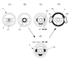
- FIGS. 3(A) to 3(E) are diagrams showing examples in which driving responsibility is transferred from the vehicle to the driver (first sensation)
- FIG. 10 is a diagram showing an example of creating a feeling that driving responsibility is transferred from the driver to the vehicle (second feeling).
- FIGS. 1 is a diagram showing a configuration example of a driving support system and a vehicle display device.
- FIG. 2(A) is a diagram showing an arrangement example in the vehicle of the projection device that constitutes the illumination unit
- FIG. 4A and 4B show an example in which the first to third display elements are expressed using perspective so that the driver perceives an image with a sense of depth (three-dimensional effect).
- FIG. 4 is a diagram showing;
- FIG. 5 is a diagram showing another example of expressing each of the first to third display elements using the perspective method so that the driver perceives an image with a sense of depth (three-dimensional effect).
- FIG. 6A is a diagram showing a display example of a pair of separated linear or band-shaped patterns (first, second, and third display elements) displayed on the steering wheel; ) shows an example of expressing the first to third display elements shown in FIG.
- FIG. 4 is a diagram showing;
- FIG. 7 expresses each of the first to third display elements shown in FIG.
- FIGS. 8A to 8G are display examples when driving responsibility shifts from the vehicle to the driver (including display indicating change in driving support level by annular pattern, highlight display, and display of gripping position). , and an example of voice guidance.
- FIG. 9 is a diagram showing an example of displaying an icon indicating a driving state (driving mode) at the center of the steering wheel.
- FIGS. 10A to 10I show display examples when driving responsibility shifts from the vehicle to the driver (display, highlighting, and grasping indicating a change in the driving support level by a separated linear or strip pattern).
- FIGS. 11A to 11E are diagrams showing an example of changing the display position and display movement direction on the steering wheel in correspondence with the action that the driver should take next
- FIGS. (J) is a diagram showing another example
- FIGS. 12(A) to 12(F) are diagrams showing an example in which the display showing the change in the driving support level and the display showing the action that the driver should take next are performed simultaneously.
- FIGS. 13A to 13E are diagrams showing display examples (modifications) in which display using an annular pattern and a pair of separated linear or band-like patterns are used together.
- FIG. 14A to 14E show that when the annular pattern is moved from the inside to the outside of the steering wheel, the width of the band-shaped pattern at the connecting portion is larger than the width of the annular pattern at the central portion and the outer edge.
- FIG. 10 is a diagram showing an example (application example) in which the value of is set to be large (wide).
- FIGS. 15A to 15H are diagrams showing display examples (including advance notification processing) when driving assistance is expanded.
- FIG. 16 is a diagram showing another example of displaying an icon indicating the driving state (driving mode) in the central portion of the steering wheel.
- FIG. 17A is a diagram showing a display example (including a mark (light mark) displayed at the center of the steering wheel) in the automatic driving state, and FIGS.
- FIG. 17B and 17C are the center of the steering wheel.
- FIG. 10 is a diagram showing another example of a mark (optical mark) displayed on the part;
- FIG. 18 is a flowchart illustrating an example of a display control procedure.
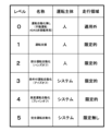
- FIG. 19 is a diagram for explaining the driving support level (automatic driving level).
- FIG. 20 is a diagram showing an example of a caution period when the driving support level (automatic driving level) is changed.
- FIG. 19 is a diagram for explaining the driving support level (automatic driving level).
- the driving support level (automatic driving level) can be divided into levels “0" to "5" as shown.
- the driving subject is a person (driver). In other words, the driver has greater driving responsibility.
- the main driver is the vehicle (vehicle system). In other words, the vehicle has more driving responsibility.
- an increase in the driving assistance level (automatic driving level) may be referred to as “expansion of the driving assistance level”, and a decrease may be referred to as “reduction in the driving assistance level”.
- FIG. 20 is a diagram showing an example of a caution period when the driving support level (automatic driving level) is changed.
- the automatic driving level is changed during the automatic driving level change period TM1 (time t1 to t2).
- the period from time t2 to t3 immediately after that is the period TM2 immediately after the automatic driving level change.
- the period from time t3 to t4 is the operation period TM3 based on the post-change level.
- FIG. 1 is a diagram showing a configuration example of a driving support system and a vehicle display device.
- the width direction of the vehicle (horizontal direction as seen from the driver) is the X direction
- the height direction of the vehicle is the Y direction
- the forward direction as seen from the driver is the Z direction.
- a driving support system (automatic driving system) 10 has an information collection unit 12 that collects various types of information from an ECU or the like, an AI module 14, a speed control module 16, and a steering control module 18.
- the display device (vehicle display device) 100 can be mounted on the vehicle (self-vehicle) 1 as an in-vehicle projector, for example.
- the display device (vehicle display device) 100 can be called a display system, a vehicle display system, an information presentation system, or a vehicle information presentation system. Hereinafter, it is written as "vehicle display device”.
- the vehicle display device 100 includes a display control device 102 having a function of controlling display in the vehicle, a voice guidance unit 105, a motion detection unit 108 for detecting motions of the driver and passengers by image processing and the like, A display control unit 110 that controls display by display devices 122 and 123 such as a liquid crystal display device provided on an instrument panel 120, a projector (projection device) 112 that can be a component of an illumination unit, and a driver and a passenger. and a motion detection camera 114 for detecting the motion of the camera.
- the display control device 102 is composed of, for example, one or more processors.
- the control unit 104 as a functional block is configured by the processor operating according to the computer program stored in the memory.
- an effective display control method can be realized simply and easily as long as there is a computer system with a basic configuration such as a processor and memory.
- the control unit 104 is supplied with, for example, various information related to the driving assistance level from the AI module 14 of the driving assistance system (automatic driving system) 10 .
- the controller 104 of the display control device 102 is notified in advance of the change in the driving assistance level. This notification is supplied to the control unit 104 as change prediction information, for example.
- control unit 104 When the change prediction information is supplied, the control unit 104 performs display control processing (first display control processing) for informing the driver of the change in the driving support level.
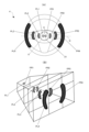
- the control unit 104 controls the operation of a projector (projection device) 112, which is a component of the lighting unit, to project an image onto the steering wheel (steering wheel) 4 of the vehicle 1, thereby displaying a display element having a two-dimensional spread. Displayable. In the lower part of FIG. 1, patterns P1 to P4 of concentric circles or rings are displayed.
- the pattern P3 displayed on the connecting portions of the steering wheel 4 (spokes: reference numerals 9a, 9b, and 9c in FIG. 2(B)) is only partially displayed as a circular or annular pattern.
- the pattern P3 is an arcuate "line pattern” when a circular pattern is projected, and an arcuate “strip pattern” when an annular pattern is projected.
- the “illumination unit” is configured by the projector (projection device) 112 alone, or by the projector 112 and a light emitting unit (having at least one light emitting element 116) provided on the steering wheel 4 of the vehicle 1. It can be assumed that it is configured, or that it is configured solely by the light-emitting portion (having a plurality of (multiple) light-emitting elements 116) provided on the steering wheel 4.
- FIG. 1 is configured by the projector (projection device) 112 alone, or by the projector 112 and a light emitting unit (having at least one light emitting element 116) provided on the steering wheel 4 of the vehicle 1. It can be assumed that it is configured, or that it is configured solely by the light-emitting portion (having a plurality of (multiple) light-emitting elements 116) provided on the steering wheel 4.
- the projector 112 is used at night, and in an environment where the intensity of outside light is strong during the day, the projector 112 and a light emitting unit including at least one light emitting element 116 are used together, or a plurality of light emitting elements are used. Applied use cases can also be envisioned, such as using only the light-emitting portion consisting of 116 .
- the projector 112 has a light source and an optical system for projection (not shown). Further, the control unit 104 can control the operation of the voice guide unit 105 to output voice (guide voice) through the speaker 107 .
- the control unit 104 can prompt the driver to grip the steering wheel by outputting, for example, a guidance voice saying, "Please hold the steering wheel.” For example, it can be displayed by a linear or band-shaped display piece (light strip) (see FIG. 9, which will be described later).
- the motion detection unit 108 analyzes the image captured by the motion detection camera 114 to detect the gripping motion, and the control unit 104 detects the gripping motion based on the detection information. to stop the output of the guide voice and the display of the display strip.
- a concave portion 6 having a circular outer shape (a circle indicating the outer shape is indicated by a broken line in FIG. 1) is provided.
- This circular concave portion 6 can be used as a central display area (symbol D1 in FIG. 2(B)) for displaying an optical mark composed of characters, figures, symbols, and the like.
- the motion detection unit 108 detects the steps (edges) of the circular concave portion 6 by image analysis, so that, for example, it is easy to accurately identify the center position of the concentric circles. can get.
- Each of the annular patterns P1 to P4 formed on the steering wheel 4 is preferably drawn by a perspective method (including linear perspective method and aerial perspective method), so that the driver can have a sense of depth.
- a perspective method including linear perspective method and aerial perspective method
- One stereoscopic image can be perceived (see FIGS. 4A, 4B, and 5; details will be described later).
- dynamic display control such as displaying the patterns P1 to P4 at different times, the driver is instructed to move from the front of the vehicle 1 toward the steering wheel 4, or from the steering wheel 4. It is also possible to give a sense of movement toward the front of the vehicle 1 (this point will also be described later).
- FIG. 2(A) is a diagram showing an arrangement example in the vehicle of the projection device that constitutes the illumination unit
- FIG. 2(B) is a front view of the steering wheel
- FIG. 2(C) is a projection on the steering wheel.
- annular pattern first and third display elements
- second display element second display element
- FIG. 2 the same reference numerals are given to the parts that are common to those in FIG. This point also applies to subsequent figures. Also, FIG. 2C is the same as the diagram shown on the lower side of FIG.
- the projector 112 is installed near the ceiling of the vehicle 1 .
- the driver 3 sits on the seat 132 and looks at the front.
- the projector 112 can project an image onto the surface of the steering wheel 4 facing the driver 3 to form a light display.
- the steering wheel 4 includes a central portion (hub or boss) 7, an outer edge portion (rim) 5, a connecting portion 9a connecting the central portion 7 and the outer edge portion 5, 9b and 9c, and has a two-dimensional structure when viewed from the driver 3.
- FIG. 2B By using each of the above portions as a display area for display elements (patterns, marks, etc.), it is possible to display an image with a two-dimensional spread.
- the external shape of the steering wheel 4 is generally a symmetrical shape that is well-proportioned to the left and right.
- the driver perceives an image with a sense of depth (three-dimensional effect) by the production of each of the above patterns (for example, a devised expression method that produces a predetermined effect), and the image , it is also possible to give a motion by the above-mentioned production effect. In other words, it is possible to make the driver 3 feel the movement toward a predetermined direction through dynamic display effects.
- FIGS. 3(A) to 3(E) are diagrams showing examples of generating a sense (first sense) that driving responsibility shifts from the vehicle to the driver
- FIGS. 3(F) to 3(J) FIG. 10 is a diagram showing an example of creating a feeling that driving responsibility is transferred from the driver to the vehicle (second feeling).
- control unit 104 of the display control device 102 provides an illumination unit (here, , the projector 112) to control the effect of display by light.
- a first display element formed in the central portion 7 of the steering wheel 4 (patterns P1 and P2 in FIGS. 3A and 3B), and a second display element formed in the connecting portions 9a to 9c (FIG. 3 (C) pattern P3) and the effect by the third display element (pattern P5 in FIG. 3(D)) formed on the outer edge portion 5 are controlled.
- the driver 3 can be made to feel a three-dimensional image with a sense of depth. 3(A) to 3(D), the patterns are displayed at different times so that the driver 3 can see the vehicle as indicated by the arrow A1 in FIG. 3(E). The movement from the front part (tip part) of 1 toward the steering wheel 4 can be felt.
- FIGS. 3A to 3D show examples in which the patterns P1 to P4 are displayed at different times, but are not limited to this.
- the patterns P1 to P4 are displayed at the same time.
- the brightness and brightness of the pattern P1 are instantaneously increased.
- a similar motion sensation can be given to the driver by causing it.
- the driving of the vehicle 1 can be improved by, for example, performing display effects using lights as shown in FIGS.
- the driver is responsible for the first sense of moving from the front portion of the vehicle 1 forward of the steering wheel 4 toward the steering wheel 4 (the sense of movement indicated by arrow A1 in FIG. 2(E)). 3 can be generated.
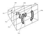
- the steering wheel 4 can be regarded as a structure that spatially separates (partitions) the front portion (tip portion) of the vehicle 1 and the driver 3 .
- one virtual plane (indicated by a dashed line in the figure) having a two-dimensional spread in real space is assumed to be in contact with the surface of the steering wheel 4.
- a virtual first responsibility area (vehicle responsibility area) AR1 is set on the front side of the vehicle 1
- a virtual second responsibility area (driving area) is set on the driver 3 side.
- Responsibility area) AR2 is set.
- the concept of the responsibility area is instantly recalled by the learning, and the person moves from the first responsibility area AR1 to the second responsibility area AR2. can be instantly recognized (understood). Therefore, the driver 3 can quickly, clearly and reliably understand that the driving assistance level has been reduced.
- the display patterns P4 to P1 are displayed in the order shown in FIGS. 3(F) to (I).
- the driver 3 can feel the movement (second sensation) of moving from the steering wheel 4 to the front of the vehicle 1, as indicated by the arrow A2 in FIG. 3(J). .
- the driver 3 can instantly recognize the transition from the second responsibility area AR2 to the first responsibility area AR1.
- the driver when the driving support level (which can be rephrased as an automatic driving level, a driving mode, etc.) is changed, the driver is given a first sense of moving from the back side to the front side as seen from the driver, and The driver can intuitively recognize the content of the change without a sense of incompatibility by performing display control (effect by a display element) that causes at least one of the second feeling of moving from the rear to the rear.
- display control effect by a display element
- the driver 3 does not follow the movement of the display element with his eyes and confirm the direction of movement to understand the change, as in the conventional art. be. Therefore, it is possible to shorten the time required for the driver to understand that the driving mode has been changed. This also contributes to safe driving and the like.
- connecting portions 9a to 9c, and outer edge portion 5 of the steering wheel 4 may not be used as areas forming display elements.
- the display elements are not formed in the connecting portions 9a to 9c. Therefore, such examples are also included in the technical scope of the present invention.
- FIGS. 4A and 4B show an example in which the first to third display elements are expressed using perspective so that the driver perceives an image with a sense of depth (three-dimensional effect).
- FIG. 4 is a diagram showing;
- Linear perspective is an expression method that expresses perspective, in which objects in the foreground appear smaller as they go further away, using line drawings.
- air perspective was originally defined as "the light that enters the eye is actually affected by the air (atmosphere), so the farther the object is from the point of view, the more air there is between the point of view and the object. It is a perspective expression method that utilizes the fact that it is sandwiched, and as a result, it becomes more bluish or the outline becomes more unclear and appears hazy.” It is a method of expressing a sense of perspective by drawing, and it can also be said to be a method of perspective using colors and tone of color (tone, outline, shadow, etc.).
- the driver can see the third display element. It can be envisioned that the display element is located near itself, the second display element is located further away, and the first display is located further away. As a result, an image with a three-dimensional effect (perceived depth) can be displayed to the driver.
- annular patterns P1 to P4 are not colored.
- FIG. 4A since the size of the annular patterns P1 to P4 increases in order, it can be said that the annular patterns P1 to P4 are represented by the method of linear perspective. Therefore, it is possible to make the driver perceive a three-dimensional image (stereoscopic image) with a sense of depth.
- the annular patterns P1 to P4 are colored blue, for example. However, the shade is different. As the density increases in the order of the patterns P1 to P4, the pattern P1 appears hazy to the driver 3, and the patterns P2 to P4 appear to improve in definition in the order. Therefore, the driver 3 can be made to perceive a clearer three-dimensional image.
- FIG. 5 is a diagram showing another example of expressing each of the first to third display elements using the perspective method so that the driver perceives an image with a sense of depth (three-dimensional effect).
- the annular patterns P1 to P4 are colored and have different colors.
- the pattern P1 is light blue
- the pattern P2 is blue
- the pattern P3 is yellow
- the pattern P4 is red.
- FIG. 6A is a diagram showing a display example of a pair of separated linear or band-shaped patterns (first, second, and third display elements) displayed on the steering wheel; ) shows an example of expressing the first to third display elements shown in FIG.
- FIG. 4 is a diagram showing;
- the display element is composed of a pair of separated linear or band-shaped display strips (light strips).
- a pair of arc-shaped display pieces PL1 and PR1, and PL2 and PR2, which are separated left and right and displayed, are the first display elements formed in the central portion 7 of the steering wheel 4.
- a pair of display pieces PL3 and PR3 are second display elements formed on the left and right connecting portions 9a and 9b of the steering wheel 4.
- a pair of display pieces PL4 and PR4 is a third display element formed on the outer edge portion 5 of the steering wheel 4. As shown in FIG.
- each display piece (PL1 to PL4, PR1 to PL4) is a virtual concentric circle (for example, 3 (A) to (D) (see patterns P1 to P4 in 3 (A) to (D)) and is arranged on a virtual straight line (mark Q in FIG. 6 (A)) that passes through the point U and intersects each concentric circle is preferred.
- the display piece can prompt the driver to step on the brake or to check the front.
- the driver can easily know that automatic driving is being carried out smoothly by changing the position of the display piece corresponding to the automatic rotation of the steering wheel. can give you peace of mind.
- a straight line in other words, By displaying (arranging) each of the pair of display pieces on the straight line forming the diameter of the maximum circle, for example, while maintaining left-right balance, etc. image can be displayed.
- a specific display example will be described later.
- FIG. 6(B) is a diagram corresponding to FIG. 4(B) shown above.
- a combination of linear perspective and aerial perspective is used to create an image with a sense of depth.
- Each display element is colored blue, for example. However, the shading is different, and the closer the display elements are to the front, the higher the definition.
- FIG. 7 expresses each of the first to third display elements shown in FIG. 6(A) using perspective in order to make the driver perceive an image with a sense of depth (three-dimensional effect). It is a figure which shows the example of.
- FIG. 7 is a diagram corresponding to FIG. 5 shown above.
- a combination of linear perspective and aerial perspective is used to create an image with a sense of depth.
- Each display element (display pattern) is colored and has a different color. Cool colors (shrinking colors) such as light blue and blue are used for patterns that are felt far from the driver 3, and warm colors (expanding colors) such as yellow and red are used for patterns that are felt close. , the sense of depth can be produced more vividly.
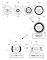
- FIGS. 8A to 8G are display examples when driving responsibility shifts from the vehicle to the driver (including display indicating change in driving support level by annular pattern, highlight display, and display of gripping position). , and an example of voice guidance.
- the display element when the driver 3 is made to feel a movement from the back side to the front side (first sensation), the display element is displayed at the outer edge portion 5 of the steering wheel 4, or at the timing. After the timing, an enhancement process is performed on the display element.
- FIGS. 8(A) to (D) are the same as FIGS. 3(A) to (D) shown above. After performing the display of FIG. 8(C) or FIG. 8(D), the display shifts to the display of FIG. 8(E).
- FIG. 8(E) the pattern P4 displayed on the outer edge 5 of the steering wheel 4 is emphasized.
- the pattern after the enhancement process is denoted by P4'.
- Endancement processing can be realized, for example, by temporarily increasing the luminance and brightness of the annular pattern or display piece, or by temporarily blinking the pattern or display piece.
- the "enhancement process” can be said to be “a process of temporarily changing the display state to improve the attractiveness”.
- the driver's vision to the display by directing the driver's vision to the display, it is possible to impress the driver that the driving support level has been changed and prevent the driver from overlooking it, or to make sure that the driver recognizes the change in the driving support level. be able to. Also, when the driving responsibility shifts from the vehicle 1 to the driver 3, the driver 2 is clearly informed of the driving responsibility and prepared to grip the steering wheel 4 (prepared in advance). Such a preparation effect can also be obtained.
- FIG. 8(E) a guide voice saying "Automatic driving section has ended” is output from the speaker 107 (see FIG. 1).
- FIG. 8F linear or strip-shaped display pieces PL4 and PR4 are displayed on the left and right sides of the outer edge 5 of the steering wheel 4 to show the driver 3 where to hold the steering wheel 4. . Also, a guide voice saying "please hold the steering wheel” is output from the speaker 107.
- FIG. 8F linear or strip-shaped display pieces PL4 and PR4 are displayed on the left and right sides of the outer edge 5 of the steering wheel 4 to show the driver 3 where to hold the steering wheel 4. .
- a guide voice saying "please hold the steering wheel” is output from the speaker 107.
- FIG. 8(G) After the display of FIG. 8(F), shift to FIG. 8(G).
- FIG. 8(G) a guide voice saying “Transition to manual operation” is output from the speaker 107.
- FIG. 8(G) a guide voice saying "Transition to manual operation" is output from the speaker 107.
- FIG. 9 is a diagram showing an example of displaying an icon indicating a driving state (driving mode) at the center of the steering wheel.
- FIG. 9 is a diagram corresponding to FIG. 8(F) shown above.
- an icon M1 is also displayed in the central display area D1 of the central portion 7 of the steering wheel 4 to prompt the user to grip the steering wheel.
- a light mark including at least one of characters, graphics, and symbols is displayed to indicate information about the driving state, the driving situation, or the next action to be taken by the driver.
- useful information can be displayed in an easy-to-see or easy-to-understand manner for the driver.
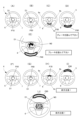
- FIGS. 10A to 10I show display examples when driving responsibility shifts from the vehicle to the driver (display, highlighting, and grasping indicating a change in the driving support level by a separated linear or strip pattern). (including display of position) and an example of voice guidance.
- FIG. 10 is a diagram corresponding to FIG. 8 shown above.
- emphasis processing is performed on linear or band-shaped display elements (patterns) (FIGS. 8(E) to (G)).
- FIGS. 10(A) to (D) are the same as FIGS. 8(A) to (D).
- FIGS. 10(H) and (I) are the same as FIGS. 8(F) and (G).
- FIG. 10 instead of FIG. 8(E), one of FIGS. 10(E) to 10(H) is highlighted.
- the emphasis processing may be performed after the display of FIG. 10(D), or after FIG. 10(C), omitting FIG. You may shift to the display of any of
- the brightness and brightness of a pair of separated linear or band-shaped (arc-shaped here) display strips (light strips) PL4′ and PR4′ are temporarily improved or temporarily
- the color, tone, or saturation is changed to enhance the attractiveness.
- FIG. 10(F) the display pieces PL5 and PR5 are temporarily extended. Comparing FIGS. 10(E) and (F), in FIG. 10(F), the display piece extends upward by L1 and downward by L2.
- FIG. 10(G) a pair of display pieces PL6 and PR6 are swung along the outer edge portion 5 of the steering wheel 4.
- FIG. 10(G) a pair of display pieces PL6 and PR6 are swung along the outer edge portion 5 of the steering wheel 4.
- the driver 3 can be prepared in advance for the action to be taken next. This contributes to safe and secure driving.
- FIGS. 11A to 11E are diagrams showing an example of changing the display position and display movement direction on the steering wheel in correspondence with the action that the driver should take next
- FIGS. (J) is a diagram showing another example.
- FIG. 11 shows a display example when other useful information (information other than the driving level change information) is displayed in relation to the notification of the driving level change.
- FIGS. 11A to 11D display pieces P10 to P40 of different sizes are attached to the center portion 7 of the steering wheel 4, the connection portion 9c extending downward from the center portion 7, and the outer edge portion 5 at different times. are displayed.
- the driver 3 moves the linear or strip-shaped display pieces P10 to P40 in a direction (here, downward) according to the next action (here, stepping on the brake).
- FIG. 11(D) a guide voice saying "Please step on the brake” is output from the speaker 107.
- the driver 3 can be made to recognize in advance what to do and be prepared. can.
- FIG. 11(E) a linear or strip-shaped display piece P40 is displayed below the outer edge of the steering wheel 4, and further, in the central display area D1 in the central portion 7 of the steering wheel 4, the brake is displayed. An icon M2 prompting stepping is displayed. This allows the driver 3 to reliably and quickly understand that the operation of stepping on the brake is necessary. Also in FIG. 11(E), the speaker 107 outputs a guide voice saying "please step on the brake".
- FIGS. 11(F) to (I) display pieces P50 to P80 of different sizes are displayed on the central portion 7 and the outer edge portion 5 of the steering wheel 4 at different times.
- the driver 3 moves the linear or strip-shaped display pieces P50 to P80 in a direction (upward in this case) according to the action to be taken next (here, an action of paying attention to the front).
- a guide voice of “Caution ahead” is output from the speaker 107 .
- an icon M3 is further displayed in the central display area D1 in the central portion 7 of the steering wheel 4 to prompt the driver to pay attention to the front.
- FIGS. 12(A) to 12(F) are diagrams showing an example in which the display showing the change in the driving support level and the display showing the action that the driver should take next are performed simultaneously.
- the example in FIG. 12 is also basically the same as the example in FIG. However, in FIG. 12, the display control shown in FIG. 6A (display control for moving a pair of display pieces left and right) and the display control shown in FIGS. ) are simultaneously performed. In this respect, it differs from FIG.
- the speaker 107 outputs a guide voice saying "Hold the steering wheel and step on the brake.”
- the speaker 107 outputs a guidance voice saying "Please hold the steering wheel and step on the brake".
- the display piece P40 that prompts him to step on the brake continues to be displayed, as shown in FIG. 12(F). Also, a guide voice saying "Please step on the brake" is repeatedly output from the speaker 107 .
- FIGS. 13A to 13E are diagrams showing display examples (modifications) in which display using an annular pattern and a pair of separated linear or band-like patterns are used together.
- annular patterns P1, P2, P3, and P4 are displayed at different times.
- FIG. 13(C) a pair of linear or strip-shaped display pieces (patterns) PL3 and PR3 are displayed on the central portion (hub) 7 of the steering wheel 4.
- FIG. 13D the pair of linear or strip-shaped display pieces (patterns) PL4 and PR4 are displayed on the left and right connecting portions (spokes) 9a and 9b of the steering wheel 4.
- spokes spokes
- FIG. 13(E) a pair of linear or strip-shaped display pieces (patterns) PL5 and PR5 are displayed at the left and right positions of the outer edge (rim) 5 of the steering wheel 4.
- the speaker 107 outputs a guidance voice saying, "The automatic driving section has ended. Please hold the steering wheel.”
- FIGS. 14A to 14E show that when the annular pattern is moved from the inside to the outside of the steering wheel, the width of the band-shaped pattern at the connecting portion is larger than the width of the annular pattern at the central portion and the outer edge.
- FIG. 10 is a diagram showing an example (application example) in which the value of is set to be large (wide).
- first circle or ring patterns P1 and P2 are sequentially displayed on the central portion 7 of the steering wheel, and in FIG. In 9c, a part (linear or strip-shaped display piece) P3 of the pattern of the second circle or ring concentric with the first circle or ring is displayed, and in FIG. , a pattern P4 of a third circle or torus that is concentric with the first and second circles or tori rings is displayed.
- FIG. 14(C) it is undeniable that the inability to display the entire circle or ring on the connecting portions 9a and 9b of the steering wheel 4 is likely to cause discomfort. Therefore, as shown in FIG. 14(E), display control is performed to suppress the discomfort.
- the line width or band width D2 of the second circle or ring is set larger than the line width or band width D1 of the first and third circles or rings.
- the display element when the display element is moved from the inside to the outside (or may be moved from the outside to the inside), the display element , 9b, the period during which a sense of discomfort occurs becomes longer.
- the band width of the light band is made larger than the band width of the rings of the central portion 7 and the outer edge portion 5. are also made large (wide) so that the connecting portions 9a and 9b can be moved quickly so that they can pass through in a short period of time. Thereby, discomfort can be reduced.
- FIGS. 15A to 15H are diagrams showing display examples (including advance notification processing) when driving assistance is expanded.
- FIGS. 15(A) to (D) are the same as FIGS. 3(F) to (I) shown above.
- the driver 3 is given a sense of motion (movement) from the near side to the far side (second sense). Is possible.
- FIGS. 15(E) and (F) before the second sensation is caused to the driver (before the display of FIG. 15(A)) in order to notify the driver 3 of the expansion of the driving assistance.
- the outer edge portion 5 of the steering wheel 4 is subjected to a display process that enhances the attractiveness.
- HL and HR indicate the left and right hands of the driver 3 who are holding the steering wheel.
- FIG. 15(E) shows an intermittent light band PQ4.
- the emphasis processing shown in FIG. 8(E) is performed first.
- FIG. 15(E), FIG. 15(F), or FIG. 15(A) a guide voice saying "Transition to automatic driving” is output from the speaker 107. After FIG. 15(E) or (F), it shifts to FIG. 15(A) or FIG. 15(B).
- FIG. 15G strip-shaped (arc-shaped) display pieces P90 to P93 are displayed on the central portion 7 of the steering wheel 4.
- FIG. 15G strip-shaped (arc-shaped) display pieces P90 to P93 are displayed on the central portion 7 of the steering wheel 4.
- strip-shaped (arc-shaped) display pieces P94 to P97 are displayed in the central display area D1 in the central portion 7 of the steering wheel 4.
- FIG. 15(H) strip-shaped (arc-shaped) display pieces P94 to P97 are displayed in the central display area D1 in the central portion 7 of the steering wheel 4.
- a guide voice saying "automatic operation has started” is output from the speaker 107.
- FIG. 16 is a diagram showing another example of displaying an icon indicating the driving state (driving mode) in the central portion of the steering wheel.
- FIG. 16 is a diagram corresponding to FIG. 9 shown above.
- an icon M4 is displayed in the central display area D1 in the central portion 7 of the steering wheel 4 to prompt the driver 3 to release the gripped steering wheel.
- the speaker 107 outputs a guidance voice saying, "Automatic driving has started. Please take your hands off the steering wheel.”
- FIG. 17A is a diagram showing a display example (including a mark (light mark) displayed at the center of the steering wheel) in the automatic driving state, and FIGS. 17B and 17C are the center of the steering wheel.
- FIG. 10 is a diagram showing another example of a mark (optical mark) displayed on the part;
- Fig. 17 shows a display example during automatic operation.
- control is performed to move strip-shaped display elements (arc-shaped display pieces) P100 and P102 in correspondence with automatic rotation of the steering wheel 4 by automatic driving control.
- the driver can visually confirm that the automatic driving is being carried out smoothly, and can obtain a sense of security.
- FIG. 17(A) in the central display area D1 of the steering wheel 4, a plurality of circles are combined to display a figure (or pattern) with a decorative effect.
- the figure (or pattern) may be given movement.
- the driver's sense of security during automatic driving can be increased, and a comfortable driving environment can be provided.
- a mark M6 indicating the manufacturer of the vehicle display device, etc. is displayed, and as shown in FIG. It is also possible to display characters indicating Further, in FIG. 17(C), the speaker 107 outputs a guidance voice saying "An ambulance is approaching.” Through such display control, it is possible to inform the driver of various types of information without causing discomfort during automatic driving.
- FIG. 18 is a flowchart illustrating an example of a display control procedure.
- step S1 change information of the autonomous driving level (prediction information of change of the driving level) is acquired from the AI module of the autonomous driving system.
- step S2 it is determined whether there is a change in the automatic driving level. If Y, the process proceeds to step S3, and it is determined whether the driving support level is reduced (whether the driving level is lowered). If Y in step S3, the process proceeds to step S4, and if N, the process proceeds to step S7.
- step S4 display control is performed to cause the driver to feel the sensation of moving from the back side to the front side (first sensation).
- step S5 an emphasizing process for emphasizing changes in the driving support level is performed.
- step S6 a display showing what the driver should do next is displayed.
- step S7 display control is performed to cause the driver to feel the sensation of moving from the near side to the far side (second sensation). Subsequently, in step S8, display processing after transition to automatic operation is performed.
- step S9 it is determined whether or not to end the display. If it is Y, the display is terminated, and if it is N, the process returns to step S1.
- the above display control method can be implemented simply and easily with a computer system having a basic configuration such as a processor and a memory. can.
- an area on the steering wheel that the driver should grip is indicated by a light mark, but if the driver does not grip the steering wheel, the light mark can be flashed or changed to a warning color and flashed. is also possible. Such changes can be made as appropriate.
- display elements, display pieces, etc. can also be rephrased as “display by light (light display)” or “light mark (light mark)”.
- display control display effect in which display elements are displayed on the steering wheel using a projector or a light-emitting element can also be referred to as "light marking.”
- vehicle can be broadly interpreted as a vehicle.
- terms related to driving assistance are also interpreted in a broad sense, taking into consideration, for example, the viewpoint of information in a broad sense that is useful for driving a vehicle.
- display devices and display devices for vehicles include those used as simulators (for example, aircraft simulators, simulators as game devices, etc.).
- Speed control module 18 Steering control module 100 Display device (vehicle display device, in-vehicle display device, or in-vehicle projector) 102 Display control device (processor) 104 Control Section 105 Audio guide section 107 Speaker 108 Action detection section 110 Display control section 112 Projector (projection section, projection light source section) for action detection Camera (occupant imaging camera) 116 Light-emitting element (or illumination element) such as LED 120 Instrument panel 122, 123 Display device (display unit) such as liquid crystal display device P1 ⁇ P4 ... Display elements formed on the steering wheel (pattern, light display, light pattern, or light mark), PL1 to PL4, ⁇ PR1 to PR4 ...
- Display pieces strip lights, arc-shaped lines, etc. or band-shaped light pattern or light mark
- D1 Central display area in the center of the steering wheel
- M1 to M7 Marks such as letters, figures, symbols displayed in the central display area (icons, including patterns, etc.).
Abstract
運転モードの変更時に、その変更内容を、運転者が違和感なく、直感的に認識できるようにする。 運転支援機能を備える車両におけるステアリングホイールに、光による表示を形成可能な照明部を制御する表示制御装置102の制御部104は、運転支援レベルの変更があった場合において、ステアリングホイール4の中央部6に形成する第1の表示要素P1、P2、連結部9a、9b、9cに形成する第2の表示要素P3、及び外縁部5に形成する第3の表示要素P4による演出を制御し、運転者3に、車両1の運転責任が、ステアリングホイールの前方にある車両1の前方部から、ステアリングホイール4に向かって移動する第1の感覚、及び、車両の運転責任が、ステアリングホイールから、車両1の前方部に向かって移動する第2の感覚、の少なくとも一方を生じさせて、運転支援レベルの変更情報を提示する。
Description
本発明は、例えば、自動車等の車両に設けられる表示制御装置、表示装置、及び表示制御方法等に関する。
自動運転機能を備える自動車に搭載され、自動運転システム等と連動して動作し、運転支援レベルの変更情報を運転者に表示(提示)する技術については、例えば、下記、特許文献1、2に開示されている。
特許文献1には、車内にプロジェクタ(照明部)を設け、ステアリングホールの外周部分である円形のリム上に局所的な照明を実施すると共に、車両の運転モードが自動運転モードから手動運転モードに切り替わるときには、リムを握っている運転者の手に近づくように照明位置を移動させ、また、自動運転モードから手動運転モードに切り替わるときは、運転者の手から遠ざかるように照明位置を移動させることが開示されている(例えば、[0047]、[0050]、図1、図3、図4)。
特許文献2では、ステアリングホイールの外周部である円形のリムの上半分に、LED等のバーライト(帯状ライト)を有する第1の照明ユニットを設け、また、ステアリングホイールの前方に位置するダッシュボードの、フロントガラスの下の位置に、細長く構成された第2の照明ユニットを設ける。第1、第2の各照明ユニットは、実際には前後方向に隔てられているが、運転者から見ると、第1、第2の各照明ユニットが連結されて、あたかも一つの共通の照明ユニットのように知覚される。自動運転から手動運転への移行時には、第1の照明ユニットから第2の照明ユニットに向かうように移動する移動光を生じさせ、手動運転から自動運転への移行時には、第2の照明ユニットから第1の照明ユニットに向かうように移動する移動光を生じさせる(例えば、[0035]、[0038]、[0042]、図2)。
特許文献1では、例えば、略三角形の光のシンボルをステアリングホイールのリム上に表示して、その光シンボルを移動させるが、その光シンボルのサイズは、ステアリングホイールの全体と比較すると、かなり小さい。
また、運転者の手に近づけたり、遠ざけたりするために光のシンボルを移動させる経路も、リムの上半分の範囲に限定される。
よって、運転者が、例えば前方に注意を払いつつ、その小さな光のシンボルの、わずかな移動を認識し、その移動の方向から、運転モードがどのように移行したかを認識することが、むずかしい場合が有り得る。よって、改善の余地がある。
また、特許文献2では、第1、第2の照明ユニットを用いて、細長い光路を形成しているため、移動光の経路は長くとることができる。
しかし、第1の照明ユニットはステアリングホイールのリムに設けられ、第2の照明ユニットは、ステアリングホイールの前方に位置するダッシュボードに設けられており、各ユニットは、空間的に分離されている。
このため、第1のユニットから第2のユニットへと光を移動させたり、第2のユニットから第1のユニットへ光を移動させたりすると、ユニットの切り替えの際に、運転者に違和感が生じる可能性は否定できない。また、光の移動経路がかなり長いため、光の移動に時間がかかるのも否めない。このことは、運転レベルの変更を、すばやく運転者に伝える点では不利である。よって、改善の余地がある。
本発明の1つの目的は、例えば、運転モードの変更時に、その変更内容を、運転者が違和感なく、直感的に認識できる表示を実現することである。
本発明の他の目的は、以下に例示する態様及び最良の実施形態、並びに添付の図面を参照することによって、当業者に明らかになるであろう。
以下に、本発明の概要を容易に理解するために、本発明に従う態様を例示する。
第1の態様において、表示制御装置は、運転支援機能を備える車両における、中央部、外縁部、及び前記中央部と前記外縁部とを連結する連結部を備えるステアリングホイールに、光による表示を形成可能な照明部を制御する表示制御装置であって、
前記ステアリングホイールの前記中央部に形成する第1の表示要素、前記連結部に形成する第2の表示要素、及び前記外縁部に形成する第3の表示要素による演出を制御する制御部を有し、
前記制御部は、
運転支援レベルの変更があった場合において、
前記ステアリングホイールの、前記第1、第2、及び第3の表示要素による演出によって、前記車両の運転者に、
前記車両の運転責任が、前記車両の、前記ステアリングホイールよりも前方にある前方部から、前記ステアリングホイールに向かって移動する第1の感覚、
及び、
前記車両の運転責任が、前記ステアリングホイールから、前記車両の前記前方部に向かって移動する第2の感覚、の少なくとも一方を生じさせて、前記運転支援レベルの変更情報を提示する。
第1の態様では、ステアリングホイールが、中央部、外縁部、及び中央部と外縁部とを連結する連結部とによって構成されて、運転者から見て、二次元的な広がりを有することを利用し、上記の各部を、表示要素(パターンやマーク等)の表示領域として利用する。
また、ステアリングホイールの外形形状は、一般に、左右に均整のとれた、シンメトリー(左右対称)形状である。このことを利用すると、例えば、運転者に、波紋が広がるような感覚を与える表示の演出や、広がった波紋が、逆に、円の中心へと縮小していくような感覚を与える表示の演出を実現することができる。
一例であるが、中心を共有する小さい円(小円)、中くらいの大きさの円(中円)、大きな円(大円)の3つの同心円を想定し、中央部に小円を表示し、連結部に中円の一部を表示し、円環形状を有する外縁部に大円を表示すると、例えば、中心から外側へと広がる波紋状の均整のとれたパターン(二次元的な広がりを感じさせるパターン)を形成することも可能である。
ここで、上記の各パターンの演出(例えば、所定効果を生じるような、工夫された表現法)によって、例えば、奥行き感(立体感)のある像を運転者に知覚させ、また、その像に、上記の演出効果によって動きを与えることもできる。
また、ステアリングホイールは、車両の前方部(先端部)と、運転者とを空間的に分ける(区画する)構造体として捉えることができる。
よって、例えば、運転者に立体感のある像を知覚させ、ステアリングホイールよりも前方の車両の部分(前方部)からステアリングホイールへと向かう(移動する)知覚を与えることで、運転者に、運転責任(運転の責任の主体)が、車両から、運転者自身へと移動(移行)したかのような感覚(第1の感覚)を生じさせることができる。また、表示の演出(特に、動きを知覚させる演出)によっては、その逆に、ステアリングホイールから車両の前方部へと移動(移行)したかのような感覚(第2の感覚)を与えることもできる。
よって、運転支援レベル(自動運転レベル、運転モード等と言い換えることができる)の変更時において、上記の表示要素による演出を実施することで、その変更内容を、運転者が違和感なく、直感的に認識できる。従来のように、運転者が、表示要素の移動を目で追って、その移動方向を確認して理解するのではなく、直感的に変更内容が理解されるため、瞬時的な理解が実現される。よって、運転モードが変更されたことを運転者に理解させるのに要する時間を短縮できる。このことは、安全運転等にも資するものである。
なお、ステアリングホイールの中央部、連結部、外縁部の内で、例えば、連結部が表示要素を形成する領域として使用されない場合もあり得る。但し、この場合は、連結部には表示要素を形成しない、という表現上の演出がなされていると考えられる。よって、このような例も、本発明の技術的範囲に含まれる。
第1の態様に従属する第2の態様において、
前記運転者から見たステアリングホイールを、実空間で2次元的広がりをもつ1つの仮想的な平面としたとき、その平面を境界として、前記車両の前方部の側に仮想的な第1の責任区が設定され、前記運転者の側に仮想的な第2の責任区が設定され、
前記制御部は、
前記運転者に、前記第1の感覚を生じさせることで、前記第1の責任区から前記第2の責任区への移行を認識させ、
前記運転者に、前記第2の感覚を生じさせることで、前記第2の責任区から前記第1の責任区への移動を認識させてもよい。
前記運転者から見たステアリングホイールを、実空間で2次元的広がりをもつ1つの仮想的な平面としたとき、その平面を境界として、前記車両の前方部の側に仮想的な第1の責任区が設定され、前記運転者の側に仮想的な第2の責任区が設定され、
前記制御部は、
前記運転者に、前記第1の感覚を生じさせることで、前記第1の責任区から前記第2の責任区への移行を認識させ、
前記運転者に、前記第2の感覚を生じさせることで、前記第2の責任区から前記第1の責任区への移動を認識させてもよい。
第2の態様では、運転者から見たステアリングホイールを、実空間で2次元的広がりをもつ1つの仮想的な平面とし、その平面の前後に、仮想的な第1の責任区、第2の責任区を設定する。
例えば、車両用表示装置の説明マニュアルに、上記の第1、第2の責任区の概念を記載しておくことで、それを読んだ運転者は、責任区の概念を学習して、記憶する。
よって、車両の運転中に、上記の第1、第2の感覚が生じたとき、その学習による責任区の概念が瞬時に想起され、責任区が移動したことを瞬時に認識(理解)することができる。よって、運転者は、運転支援レベルの変更内容を、素早く、明確、かつ確実に理解することができる。
第1又は第2の態様に従属する第3の態様において、
前記制御部は、
運転支援が縮小される場合は、前記運転者に、前記第1の感覚を生じさせ、
運転支援が拡大される場合は、前記運転者に、前記第2の感覚を生じさせてもよい。
前記制御部は、
運転支援が縮小される場合は、前記運転者に、前記第1の感覚を生じさせ、
運転支援が拡大される場合は、前記運転者に、前記第2の感覚を生じさせてもよい。
第3の態様によれば、運転支援が縮小したのか、拡大したのかを、運転者に、正確に知らせることができる。
なお、運転支援の縮小とは、言い換えれば、自動運転レベルが下がることであり、運転支援の拡大とは、言い換えれば、自動運転レベルが上がることである。
特に、自動運転レベルの変更によって、車両の運転主体が、車両から運転者へと移行(移動)する場合、ならびに、運転者から車両へと移行(移動)する場合においては、運転者が、その変更内容を素早く、かつ確実に理解する必要がある。
本発明によれば、運転主体の変更があったときでも、どちらが、車両の運行に責任をもつのか、を瞬時に、かつ正確に知らせることができる。よって、運転者は、車両の運行中において安心感を得ることができる。
第1乃至第3の何れか1つの態様に従属する第4の態様において、
前記制御部は、
前記ステアリングホイールの、前記第1、第2、及び第3の表示要素による演出を実施する際、
前記第1、第2、第3の各表示要素に基づいて、前記運転者が知覚する一つの像が、奥行き感のある立体的な像となるように、前記第1、第2、第3の各表示要素を、遠近法を用いて表現すると共に、
前記第1、第2、第3の各表示要素を、時間を異にして表示する、又は、前記第1、第2、第3の各表示要素の表示状態の変化を、時間を異にして生じさせ、前記運転者に、動きを感じさせてもよい。
前記制御部は、
前記ステアリングホイールの、前記第1、第2、及び第3の表示要素による演出を実施する際、
前記第1、第2、第3の各表示要素に基づいて、前記運転者が知覚する一つの像が、奥行き感のある立体的な像となるように、前記第1、第2、第3の各表示要素を、遠近法を用いて表現すると共に、
前記第1、第2、第3の各表示要素を、時間を異にして表示する、又は、前記第1、第2、第3の各表示要素の表示状態の変化を、時間を異にして生じさせ、前記運転者に、動きを感じさせてもよい。
第4の態様では、遠近法、及び動的な表現を用いた演出によって、第1~第3の態様において示したような視覚的効果が実現される。
第1、第2、第3の各表示要素を、1つの像の構成要素とみなす場合、各表示要素(1つの像の各構成要素)を、遠近法を用いて表現することで、運転者に、その1つの像を、奥行き感のある立体的な像と知覚させることができる。
また、第1、第2、第3の各表示要素の表示タイミングを時間軸上でずらすことで、運転者に、動きがあると感じさせることができる。
また、第1、第2、第3の各表示自体は、時間軸上で同時に表示されるが、各表示に生じる表示状態の変化(例えば、輝度や明度が瞬時的に上昇するという表示状態の変化)を、時間を異にして生じさせることによっても、運転者に動きがあると感じさせることができる。
なお、第1、第2、第3の各表示要素の表示タイミングを時間軸上でずらす場合であっても、タイミング差が小さければ、残像効果(視認者が光や像を見たとき、その光や像が消えた後も、それまで見ていた光や映像が残って見える効果)によって、運転者は1つの像を知覚(認識)することができる。
第1乃至第3の何れか1つの態様に従属する第5の態様において、
前記制御部は、
前記ステアリングホイールの、前記第1、第2、及び第3の表示要素による演出を実施する際、
前記第1、第2、第3の各表示要素に基づいて、前記運転者が知覚する一つの像が、奥行き感のある立体的な像となるように、前記第1、第2、第3の各表示要素を、遠近法を用いて表現すると共に、
前記運転者に、前記第1の感覚を生じさせる場合には、
時間を異にして、前記第1、第2、第3の表示要素の順に表示させて、運転者から見て、奥側から手前側に向かう動きを感じさせ、
又は、
前記第1、第2、第3の表示要素を同時に表示し、かつ、時間を異にして、前記第1、第2、第3の表示要素の順に表示状態を変化させて、運転者から見て、奥側から手前側へと向かう動きを感じさせ、
前記第2の感覚を生じさせる場合には、
時間を異にして、前記第3、第2、第1の表示要素の順に表示させて、運転者から見て、手前側から奥側に向かう動きを感じさせ、
又は、
前記第1、第2、第3の表示要素を同時に表示し、かつ、時間を異にして、前記第3、第2、第1の表示要素の順に表示状態を変化させて、運転者から見て、手前側から奥側に向かう動きを感じさせてもよい。
第5の態様は、第4の態様に示した表示要素上の演出について、より詳細に記載したものである。第5の態様においても、遠近法、及び動的な表現を用いた演出によって、第1~第3の態様において示したような視覚的効果が実現される。
第1、第2、第3の各表示要素の表示順、あるいは、表示状態を変化させる場合の順番を制御することで、上記の第1の感覚、及び第2の感覚を、効果的に生じさせることができる。
第5の態様に従属する第6の態様において、
前記制御部は、
前記第1、第2、第3の各表示要素を、遠近法を用いて表現する際、
前記1、第2、第3の表示要素の順に、その表示要素の大きさを大きくすることで、線遠近法による遠近感を生じさせ、
又は、
前記1、第2、第3の表示要素の順に、その表示要素の大きさを大きくすることで、線遠近法による第1の遠近感を生じさせ、かつ、前記第1、第2、第3の各表示要素を、空気遠近法によって表現して、前記第1の遠近感と方向性が合致する第2の遠近感を生じさせてもよい。
前記制御部は、
前記第1、第2、第3の各表示要素を、遠近法を用いて表現する際、
前記1、第2、第3の表示要素の順に、その表示要素の大きさを大きくすることで、線遠近法による遠近感を生じさせ、
又は、
前記1、第2、第3の表示要素の順に、その表示要素の大きさを大きくすることで、線遠近法による第1の遠近感を生じさせ、かつ、前記第1、第2、第3の各表示要素を、空気遠近法によって表現して、前記第1の遠近感と方向性が合致する第2の遠近感を生じさせてもよい。
第6の態様では、線遠近法、又は、線遠近法と空気遠近法との併用によって、運転者に、奥行き感のある立体的な像を知覚させる。
ここで「遠近法」とは、視覚的に遠近感を表現する手法である。「線遠近法」は、手前のものから奥に遠ざかるにつれて小さく見えるという遠近法を線画によって表現する表現方法である。
また「空気遠近法」は、元々は、「目に入る光は、実際は空気(大気)の影響を受けており、よって視点から遠くにあるものほど、視点と対象物の間に多量の空気を挟み、その影響で、より青みがかったり、より輪郭線が不明瞭になって霞んで見えたりすることを利用した遠近表現方法」であり、典型的には、「遠くのものほど淡く霞ませるように描写することで遠近感を表現する方法であり、色や色の調子等(色調、輪郭、ならびに陰影等)を用いた遠近法ということもできる表現方法」である。
空気遠近法の使用例とはしては、例えば、第1、第2、第3の表示要素の順に、輝度や明度を高くして鮮明性を向上させることで、運転者に、第3の表示要素が自身の近くに位置し、第2の表示要素は、より遠くに位置し、第1の表示は、さらに遠くに位置するように感得させることが想定され得る。これによって、運転者に、立体感(奥行き感)のある像を表示することができる。
第1乃至第6の何れか1つの態様に従属する第7の態様において、
前記第1、第3の各表示要素は、円又は円環状の形状であり、前記第2の表示要素は、前記連結部の一部に形成される線状、又は帯状の表示片である、
又は、
前記第1、第2、第3の各表示要素は、分離された一対の線状又は帯状の表示片を有する、
又は、
前記第1、第2、第3の各表示要素は、分離された一対の、線状又は帯状の表示片を有し、かつ、前記各表示片は、前記ステアリングホイールの前記中央部に設定される一点を中心とする仮想的な同心円上であって、前記一点を通って、各同心円と交わる仮想的な直線上に配置されてもよい。
前記第1、第3の各表示要素は、円又は円環状の形状であり、前記第2の表示要素は、前記連結部の一部に形成される線状、又は帯状の表示片である、
又は、
前記第1、第2、第3の各表示要素は、分離された一対の線状又は帯状の表示片を有する、
又は、
前記第1、第2、第3の各表示要素は、分離された一対の、線状又は帯状の表示片を有し、かつ、前記各表示片は、前記ステアリングホイールの前記中央部に設定される一点を中心とする仮想的な同心円上であって、前記一点を通って、各同心円と交わる仮想的な直線上に配置されてもよい。
第7の態様では、各表示光の形状(ならびに、その配置)を例示している。
例えば、各表示要素によって、同心円(同心円環)を基本とするパターンを表示してもよい。
また、各同心円(同心円環)の外周に沿う円弧等の、線状、帯状の、一対の互いに分離された表示片を表示してもよい。円弧等の、線状、帯状の表示片を用いると、運転支援レベルの変更内容のみならず、他の有用な情報を、運転者にわかり易く伝えること等もできる。
例えば、運転支援が縮小されて手動運転モードとなった場合に、ステアリングホイールの外縁部の、運転者が把持する領域を、その表示片で示したり、その表示片の表示位置を変更して、例えば、ブレーキを踏むことや、前方を確認することを、その表示片で促したりすることができる。
また、自動運転モードに切り替わった後、ステアリングホイールの自動回転に対応させて表示片の位置を変更することで、運転者は、自動運転が順調に実施されていることを容易に知ることができ、安心感を得ることができる。
また、その各表示片を表示するとき、各同心円(同心円環)上で、かつ、その円(円環)の中心を通って、各円(円環)と交差するような直線(言い換えれば、最大円の直径を構成する直線)上に、一対の表示片の各々を、例えば、左右等のバランスを保ちつつ表示(配置)していくことで、左右等に均整のとれた、違和感のない像を表示することができる。
第5の態様に従属する第8の態様において、
制御部は、
前記運転者に、前記第1の感覚を生じさせる場合において 前記第3の表示要素の表示タイミングで、あるいは、前記第3の表示要素を表示した後に、前記第3の表示要素を強調する強調処理を実施する、
又は、
前記第3の表示要素における表示状態の変化のタイミングで、あるいは、前記第3の表示要素における表示状態が変化した後に、前記第3の表示要素を強調する強調処理を実施してもよい。
制御部は、
前記運転者に、前記第1の感覚を生じさせる場合において 前記第3の表示要素の表示タイミングで、あるいは、前記第3の表示要素を表示した後に、前記第3の表示要素を強調する強調処理を実施する、
又は、
前記第3の表示要素における表示状態の変化のタイミングで、あるいは、前記第3の表示要素における表示状態が変化した後に、前記第3の表示要素を強調する強調処理を実施してもよい。
第8の態様では、各表示要素を、時間をずらして表示する、又は、各表示要素の表示状態の変化を、時間をずらして生じさせることで、運転者に、奥側から手前側に向かう動き(第1の感覚)を感じさせる場合に、第3の表示要素を、ステアリングホイールの外縁部に表示するタイミングで、あるいは、そのタイミングの後に、その第3の表示要素に対して強調処理を実施する。
「強調処理」は、例えば、第3の表示片の輝度や明度を一時的に上昇させたり、第3の表示片を一時的に点滅させたりすることで実現可能である。「強調処理」は、言い換えれば、「表示状態を一時的に変更して誘目性を向上させる処理」ということができる。運転者の視覚を、その表示に向けさせることで、運転支援レベルの変更があったことを運転者に印象づけて見逃しを防止したり、運転支援レベルの変更内容を確実に認識させたりすることができる。
また、運転責任が、車両から運転者に移動する場合に、運転者に、運転責任があることを明確に知らせて、ステアリングホイールを握る準備をさせる(心構えを事前に持たせる)というような、事前準備効果も得られる。
第8の態様に従属する第9の態様において、
前記制御部は、
前記強調処理において、
前記第3の表示要素の、輝度、明度を一時的に向上させ、または、一時的に色、又は、色調、又は彩度を変更させ、
又は、
前記第3の表示要素が、分離された一対の線状又は帯状の表示片である場合には、前記表示片の長さを、一時的に伸長させる、
又は、
前記第3の表示要素が、分離された一対の線状又は帯状の表示片である場合には、前記表示片を、前記ステアリングホイールの前記外縁部に沿って揺動させてもよい。
前記制御部は、
前記強調処理において、
前記第3の表示要素の、輝度、明度を一時的に向上させ、または、一時的に色、又は、色調、又は彩度を変更させ、
又は、
前記第3の表示要素が、分離された一対の線状又は帯状の表示片である場合には、前記表示片の長さを、一時的に伸長させる、
又は、
前記第3の表示要素が、分離された一対の線状又は帯状の表示片である場合には、前記表示片を、前記ステアリングホイールの前記外縁部に沿って揺動させてもよい。
第9の態様では、強調処理の具体例を例示している。第3の表示要素の色等の一時的な変更、長さの一時的な変更、あるいは、第3の表示要素を揺れているかのように動かすといった位置制御等によって、誘目性を一時的に向上させることができる。
第1乃至第9の態様の何れか1つに従属する第10の態様において、
前記制御部は、
前記ステアリングホイールの前記外縁部において、前記運転者が、左手及び右手の各々で把持する領域を示す、線状又は帯状の表示片を表示させる、
又は、
前記ステアリングホイールの前記外縁部において、前記運転者が次にするべき行動に対応する位置に、線状又は帯状の表示片を表示させる、
又は、
前記ステアリングホイールの前記中央部、又は、前記中央部及び前記連結部において、前記運転者が次にするべき行動に応じた方向に、線状又は帯状の表示片を移動させる、又は、自動運転によるステアリングホイールの自動的な回転に対応させて、線状又は帯状の表示片を移動させてもよい。
前記制御部は、
前記ステアリングホイールの前記外縁部において、前記運転者が、左手及び右手の各々で把持する領域を示す、線状又は帯状の表示片を表示させる、
又は、
前記ステアリングホイールの前記外縁部において、前記運転者が次にするべき行動に対応する位置に、線状又は帯状の表示片を表示させる、
又は、
前記ステアリングホイールの前記中央部、又は、前記中央部及び前記連結部において、前記運転者が次にするべき行動に応じた方向に、線状又は帯状の表示片を移動させる、又は、自動運転によるステアリングホイールの自動的な回転に対応させて、線状又は帯状の表示片を移動させてもよい。
第10の態様では、運転レベルの変更の報知に関連して、他の有益な情報(運転レベルの変更情報以外の情報)を表示する場合の表示例を示す。
例えば、運転主体が車両から運転者に移行する場合、その移行の途中や移行後において、線状や帯状の表示片を、ステアリングホイールの外縁部の左右位置に表示することで、運転者に、ステアリングホイールの把持位置を示すことができる。
また、線状又は帯状の表示片の表示位置を、運転者が次にするべき行動に対応させて変更することで、運転者に、何をすべきかを事前に認識させて、心構えを持たせることができる。例えば、ブレーキを踏む操作が必要な場合は、ステアリングホイールの外縁部の下側に、線状又は帯状の表示片を表示してもよい。
また、ステアリングホイールの中央部、あるいは、中央部及び連結部において、表示片(広義には所定の光パターンや光マーク)を、次に運転者がするべき行動に対応した方向に移動させることで、運転者に、何をすべきかを事前に認識させて、心構えを持たせることができる。例えば、斜め前方に注意を払うように促す場合には、表示片(広義には光パターンや光マーク)を、中央部において斜め上方へと移動させてもよい。
第1乃至第10の態様の何れか1つに従属する第11の態様において、
前記制御部は、
前記ステアリングホイールの前記中央部に、運転状態、又は、運転状況、又は、運転者が次に行うべき動作に関する情報を示す、文字、図形、及び記号の少なくとも1つを含む光マークを表示する、
又は、
前記ステアリングホイールの前記中央部に、運転状態、又は、運転状況、又は、運転者が次に行うべき動作に関する情報を示す、文字、図形、及び記号の少なくとも1つを含む光マークを表示し、かつ、音声によって、前記情報を報知させてもよい。
前記制御部は、
前記ステアリングホイールの前記中央部に、運転状態、又は、運転状況、又は、運転者が次に行うべき動作に関する情報を示す、文字、図形、及び記号の少なくとも1つを含む光マークを表示する、
又は、
前記ステアリングホイールの前記中央部に、運転状態、又は、運転状況、又は、運転者が次に行うべき動作に関する情報を示す、文字、図形、及び記号の少なくとも1つを含む光マークを表示し、かつ、音声によって、前記情報を報知させてもよい。
第11の態様では、ステアリングホイールの中央部において、運転者に有益な情報を提示可能な光マークを表示する。これによって、運転者に、有益な情報を、見易く、あるいは、理解し易く表示することができる。
また、音声による案内を併用して、上記の有益な情報を音声で運転者に伝えることもできる。これにより、より正確に情報を伝えることができる。また、運転状況等を、視覚と聴覚を介して認識できるため、情報の理解が促進される。
第1乃至第11の何れか1つの態様に従属する第12の態様において、
前記制御部は、
前記運転者に、前記第2の感覚を生じさせる前に、
前記ステアリングホイールの前記外縁部において、誘目性を高める表示処理を実施してもよい。
前記制御部は、
前記運転者に、前記第2の感覚を生じさせる前に、
前記ステアリングホイールの前記外縁部において、誘目性を高める表示処理を実施してもよい。
第12の態様によれば、運転支援レベルの拡大を運転者に伝える場合に、事前に、誘目性を高める表示をステアリングホイールに表示することにより、例えば、運転者に、運転レベルの変更があったことを示す表示が開始されることを瞬時に理解させることができる。よって、事前に心構えを持たせることができる。よって、例えば、唐突に光の演出が開始されることによる違和感を軽減する等の効果を得ることができる。
第1乃至第12の何れか1つの態様に従属する第13の態様において、
前記制御部は、
前記ステアリングホイールの前記中央部に、第1の円又は円環を表示し、
前記連結部に、前記第1の円又は円環と同心である第2の円又は円環の一部を表示し、
前記外縁部に、前記第1、第2の円又は円環と同心である第3の円又は円環を表示する場合に、
前記第2の円又は円環の線幅又は帯幅を、前記第1、第3の円又は円環の線幅又は帯幅よりも大きく設定してもよい。
前記制御部は、
前記ステアリングホイールの前記中央部に、第1の円又は円環を表示し、
前記連結部に、前記第1の円又は円環と同心である第2の円又は円環の一部を表示し、
前記外縁部に、前記第1、第2の円又は円環と同心である第3の円又は円環を表示する場合に、
前記第2の円又は円環の線幅又は帯幅を、前記第1、第3の円又は円環の線幅又は帯幅よりも大きく設定してもよい。
第13の態様では、ステアリングホイールの連結部において、円や円環の全体を表示できないことによる違和感が生じ易いため、この違和感を抑制する表示制御を実施する。
例えば、第3の円環の直径を徐々に縮小して第2の円環へと移動させ、さらに、第2の円環の直径を徐々に縮小して第1の円環へと移動させるような表示制御を行う場合を想定する(但し、この逆の移動であってもよい)。
この場合、連結部を通過するのに時間がかかると、違和感が生じる期間が長くなってしまう。そこで、連結部における光の帯の通過時間を短縮するために、その光の帯の帯幅を、中央部や外縁部の円環における帯幅よりも大きく(広く)して、連結部を、素早く移動させて、短時間で通過できるようにした。これにより、違和感を軽減することができる。
第14の態様において、表示装置は、
車両に設けられる、第1乃至第13の何れか1つの態様の表示制御装置と、
前記車両に設けられ、前記表示制御装置によって発光が制御される照明部と、を有する。
車両に設けられる、第1乃至第13の何れか1つの態様の表示制御装置と、
前記車両に設けられ、前記表示制御装置によって発光が制御される照明部と、を有する。
第14の態様により、運転モードの変更時に、その変更内容を、運転者に、違和感なく、直感的に認識できるように表示できる車両用表示装置(具体的には、例えば、車内プロジェクタ)を実現することができる。
第14の態様に従属する第15の態様では、
前記照明部は、
前記車両のステアリングホイールに光を投影して照明するプロジェクタを有する、
又は、
前記車両のステアリングホイールに光を投影して照明するプロジェクタと、前記ステアリングホイールに設けられる発光素子とを有する、
又は、
前記ステアリングホイールに設けられる発光素子を有してもよい。
前記照明部は、
前記車両のステアリングホイールに光を投影して照明するプロジェクタを有する、
又は、
前記車両のステアリングホイールに光を投影して照明するプロジェクタと、前記ステアリングホイールに設けられる発光素子とを有する、
又は、
前記ステアリングホイールに設けられる発光素子を有してもよい。
第15の態様では、照明部の構成例が示されている。
照明部は、光を投影して照明するプロジェクタであってもよく、プロジェクタと、ステアリングホイールに設けられた発光素子(少なくとも1個の発光素子)を有する構成であってもよく、また、ステアリングホイールに設けられた発光素子(複数の発光素子)のみで構成されるものであってもよい。
例えば、夜間にはプロジェクタのみを使用し、昼間の外光の強度が強い環境等では、プロジェクタと発光素子とを併用する、あるいは、発光素子のみを使用する、といった、応用的な使用例も想定され得る。
第16の態様において、表示制御方法は、
運転支援機能を備える車両における、中央部、外縁部、及び前記中央部と前記外縁部とを連結する連結部を備えるステアリングホイールに、光による表示を形成する表示制御方法であって、
運転支援レベルの変更があった場合において、
前記ステアリングホイールの前記中央部に形成する第1の表示要素、前記連結部に形成する第2の表示要素、及び前記外縁部に形成する第3の表示要素による演出を制御することによって、
前記車両の運転者に、
前記車両の運転責任が、前記車両の、前記ステアリングホイールよりも前方にある前方部から、前記ステアリングホイールに向かって移動する第1の感覚、
及び、
前記車両の運転責任が、前記ステアリングホイールから、前記車両の前記前方部に向かって移動する第2の感覚、の少なくとも一方を生じさせて、前記運転支援レベルの変更情報を提示する。
第16の態様によれば、運転支援レベルの変更時において、表示要素による演出を実施することで、その変更内容を、運転者が違和感なく、直感的に認識できる。従来のように、運転者が、表示要素の移動を目で追って、その移動方向を確認して理解するのではなく、直感的に変更内容が理解されるため、瞬時的な理解が実現される。よって、運転モードが変更されたことを運転者に理解させるのに要する時間を短縮できる。このことは、安全運転等にも資するものである。
また、コンピュータプログラムを用いる場合は、プロセッサやメモリ等の基本的な構成を備えるコンピュータシステムがあれば、簡単に、かつ容易に、上記の表示制御方法を実現することができる。
当業者は、例示した本発明に従う態様が、本発明の精神を逸脱することなく、さらに変更され得ることを容易に理解できるであろう。
以下に説明する最良の実施形態は、本発明を容易に理解するために用いられている。従って、当業者は、本発明が、以下に説明される実施形態によって不当に限定されないことを留意すべきである。
まず、図19を参照する。図19は、運転支援レベル(自動運転レベル)について説明するための図である。運転支援レベル(自動運転レベル)は、図示されるように、レベル「0」~レベル「5」に区分され得る。レベル「0」~「2」では、運転主体は人(運転者)である。言い換えれば、運転者に、より重い運転責任がある。また、レベル「3」~レベル「5」では、運転主体は車両(車両のシステム)である。言い換えれば、車両に、より重い運転責任がある。
本明細書では、運転支援レベル(自動運転レベル)の上昇を、「運転支援レベルの拡大」と称する場合があり、その下降を、「運転支援レベルの縮小」と称する場合がある。
次に、図20を参照する。図20は、運転支援レベル(自動運転レベル)が変更される場合の、要注意期間の例を示す図である。
自動運転レベル変更期間TM1(時刻t1~t2)において、自動運転レベルが変更される。その直後の時刻t2~t3の期間が、自動運転レベル変更直後期間TM2である。時刻t3~t4の期間が、変更後のレベルによる運転期間TM3である。各期間TM1~TM3の各々において、運転者に、光による、あるいは、光と音声の併用による情報提示を、適切に実施することが好ましい。その際、運転者が、違和感なく、かつ迅速に情報を認識(理解)できるようにするのが好ましい。
次に、図1を参照する。図1は、運転支援システム及び車両用表示装置の構成例を示す図である。なお、図1において、車両の幅方向(運転者から見た左右方向)をX方向とし、車両の高さ方向をY方向とし、運転者から見た前方方向をZ方向とする。
運転支援システム(自動運転システム)10は、ECU等から各種情報を収集する情報収集部12と、AIモジュール14と、速度制御モジュール16と、操舵制御モジュール18と、を有する。
表示装置(車両用表示装置)100は、例えば車内プロジェクタとして車両(自車両)1に搭載され得る。なお、表示装置(車両用表示装置)100は、表示システム、車両用表示システム、情報提示システム、あるいは車両用情報提示システムと言い換えることができる。以下、「車両用表示装置」と表記する。
車両用表示装置100は、車内における表示を制御する機能を有する表示制御装置102と、音声ガイド部105と、画像処理等によって運転者や乗員の動作を検出する動作検出部108と、車両1のインスツルメントパネル120に設けられる液晶表示装置等の表示器装置122、123による表示を制御する表示器制御部110と、照明部の構成要素となり得るプロジェクタ(投影装置)112と、運転者や乗員の動作を検出する動作検出用カメラ114と、を有する。
表示制御装置102は、例えば、1又は複数のプロセッサにより構成される。このプロセッサが、メモリに格納されているコンピュータプログラムに従って動作することで、機能ブロックとしての制御部104が構成される。
コンピュータプログラムを用いる場合、プロセッサやメモリ等の基本的な構成を備えるコンピュータシステムがあれば、簡単に、かつ容易に、効果的な表示制御方法を実現することができる。
制御部104には、運転支援システム(自動運転システム)10のAIモジュール14から、例えば、運転支援レベルに関する各種の情報が供給される。例えば、運転支援レベルが変更される場合は、運転支援レベルの変更があることを、事前に表示制御装置102の制御部104に通知する。この通知は、例えば、変更予測情報として、制御部104に供給される。
制御部104は、その変更予測情報が供給されると、運転支援レベルの変更を運転者に報知するための表示制御処理(第1表示制御処理)を実施する。
制御部104は、照明部の構成要素であるプロジェクタ(投影装置)112の動作を制御して、車両1のステアリングホイール(ハンドル)4に画像を投影し、二次元的な広がりを有する表示要素を表示可能である。図1の下側には、同心円状の円又は円環のパターンP1~P4が表示されている。
但し、ステアリングホイール4の連結部(スポーク:図2(B)の符号9a、9b、9c)に表示されるパターンP3は、円又は円環のパターンの一部のみが表示される。
なお、円、円環はいずれも外形は円であるが、円環の方が、線幅が広い。パターンP3は、円のパターンが投影される場合には円弧状の「線状パターン」となり、円環のパターンが投影される場合には、円弧状の「帯状パターン」となる。
また、「照明部」は、プロジェクタ(投影装置)112単独で構成される場合と、プロジェクタ112、及び車両1のステアリングホイール4に設けられる発光部(少なくとも1個の発光素子116を有する)とにより構成される場合と、ステアリングホイール4に設けられる発光部(複数(多数)の発光素子116を有する)単独によって構成される場合とが想定され得る。
例えば、夜間にはプロジェクタ112のみを使用し、昼間の外光の強度が強い環境等では、プロジェクタ112と、少なくとも1個の発光素子116からなる発光部とを併用する、あるいは、複数の発光素子116からなる発光部のみを使用する、といった、応用的な使用例も想定され得る。
以下の説明では、プロジェクタ112によって、投影画像をステアリングホイール4上に表示する場合について説明する。
プロジェクタ112は、投影用の光源と光学系を有する(不図示)。また、制御部104は、音声ガイド部105の動作を制御して、スピーカ107を介して音声(ガイド音声)を出力させることが可能である。
制御部104は、例えば、「ハンドルを握って下さい」というガイド音声を出力させて、運転者に、ステアリングホイールの把持を促すことができ、これと併行して、ステアリングホイール4における把持領域を、例えば線状又は帯状の表示片(ライトストリップ)によって表示することができる(図9参照。この点については後述する)。
また、運転者がステアリングホイール4を把持すると、動作検出部108が、動作検出用カメラ114により撮像された画像を解析して、その把持動作を検出し、制御部104は、その検出情報に基づいて、ガイド音声の出力や表示片の表示を停止させる。
また、ステアリングホイール4の中央部(図2(B)の符号7)には、外形が円形の凹部6(図1では、外形を示す円が破線で示されている)が設けられている。この円形の凹部6は、文字、図形、記号等を構成要素とする光マークを表示する中央表示領域(図2(B)の符号D1)として利用可能である。
また、動作検出部108が、画像解析によって、その円形の凹部6の段差(エッジ)を検出することで、例えば、同心円の中心の位置を正確に特定することが容易化される等の効果が得られる。
また、ステアリングホイール4上に形成される円環状の各パターンP1~P4は、好ましくは遠近法(線遠近法、空気遠近法を含む)によって描画され、これによって、運転者は、奥行き感のある1つの立体像を感得し得る(図4(A)、(B)、図5参照:詳細は後述する)。
また、各パターンP1~P4を、時間を異にして表示する等の動的な表示制御によって、運転者に、車両1の前方部からステアリングホイール4に向かうような動き、あるいは、ステアリングホイール4から車両1の前方部に向かうような動きを感じさせることも可能である(この点も後述する)。
次に、図2を参照する。図2(A)は、照明部を構成する投影装置の車内における配置例を示す図、図2(B)は、ステアリングホイールの正面図、図2(C)は、ステアリングホイール上に投影される、円環状のパターン(第1、第3の表示要素)、及び、帯状パターン(第2の表示要素)を示す図である。
図2において、図1と共通する部分には、同じ符号を付している。この点は、以降の図においても同様である。また、図2(C)は、図1の下側に示される図と同じである。
図2(A)に示されるように、プロジェクタ112は、車両1の天井付近に設置されている。運転者3は、座席132に着座して正面を見ている。プロジェクタ112は、画像を、ステアリングホイール4の、運転者3側の表面に投影して、光による表示を形成可能である。
図2(B)に示されるように、ステアリングホイール4は、中央部(ハブ、あるいはボス)7と、外縁部(リム)5と、中央部7と外縁部5とを連結する連結部9a、9b、9cとによって構成されて、運転者3から見て、二次元的な広がりを有する構造を有する。上記の各部を、表示要素(パターンやマーク等)の表示領域として利用することで、2次元的な広がりのある画像の表示が可能となる。
また、ステアリングホイール4の外形形状は、一般に、左右に均整のとれた、シンメトリー(左右対称)形状である。このことを利用すると、例えば、運転者3に、波紋が広がるような感覚を与える表示の演出や、広がった波紋が、逆に、円の中心へと縮小していくような感覚を与える表示の演出を実現することができる。
一例であるが、中心を共有する小さい円(小円)、中くらいの大きさの円(中円)、大きな円(大円)の3つの同心円を想定し、中央部に小円を表示し、連結部に中円の一部を表示し、円環形状を有する外縁部に大円を表示すると、例えば、中心から外側へと広がる波紋状の均整のとれたパターン(二次元的な広がりを感じさせるパターン)を形成することも可能である(図2(C)参照)。
ここで、上記の各パターンの演出(例えば、所定効果を生じるような、工夫された表現法)によって、例えば、奥行き感(立体感)のある像を運転者に知覚させ、また、その像に、上記の演出効果によって動きを与えることもできる。言い換えれば、動的な表示の演出によって、運転者3に所定の方向に向かう動きを感得させることが可能である。
この点について、具体的に説明する。図3を参照する。図3(A)~(E)は、運転責任が、車両から運転者に移行するような感覚(第1の感覚)を生じさせる例を示す図、図3(F)~(J)は、運転責任が、運転者から車両に移行するような感覚(第2の感覚)を生じさせる例を示す図である。
先に説明したように、表示制御装置102の制御部104は、中央部7、外縁部5、及び連結部9a~9cを備えるステアリングホイール4に、光による表示を形成可能な照明部(ここでは、プロジェクタ112)を制御し、光による表示の演出を制御する。
例えば、ステアリングホイール4の中央部7に形成する第1の表示要素(図3(A)、(B)のパターンP1、P2)、連結部9a~9cに形成する第2の表示要素(図3(C)のパターンP3)、及び外縁部5に形成する第3の表示要素(図3(D)のパターンP5)による演出を制御する。
各表示要素P1~P4を、遠近法を用いて表示することで、奥行き感のある立体的な像を、運転者3に感じさせることができる。また、図3(A)~図3(D)の順に、時間を異にして、各パターンを表示することで、運転者3に、図3(E)の矢印A1で示されるような、車両1の前方部(先端部)からステアリングホイール4に向かう動きを感じさせることができる。
図3(A)~(D)の例では、時間を異にして、各パターンP1~P4を表示する例を示しているが、これに限定されるものではない。例えば、各パターンP1~P4を同時に表示し、まず、パターンP1の輝度や明度を瞬時的に高め、以下、パターンP2、P3、P4の順に、同様の表示状態の変化を、時間を異にして生じさせることによっても、同様の動きの感覚を、運転者に与えることができる。
なお、各表示要素の表示タイミングを時間軸上でずらす場合であっても、タイミング差が小さければ、残像効果(視認者が光や像を見たとき、その光や像が消えた後も、それまで見ていた光や映像が残って見える効果)によって、運転者は1つの像を知覚(認識)することができる。
運転支援レベルが縮小されて、運転主体が車両から運転者に移行する場合において、例えば、図3(A)~(D)のような光による表示の演出を実施することで、車両1の運転責任が、車両1の、ステアリングホイール4よりも前方にある前方部から、ステアリングホイール4に向かって移動する第1の感覚(図2(E)の矢印A1で示される移動感覚)を、運転者3に生じさせることができる。
また、ステアリングホイール4は、車両1の前方部(先端部)と、運転者3とを空間的に分ける(区画する)構造体として捉えることができる。
ここで、図2(E)に示されるように、ステアリングホイール4の表面に接して、実空間で2次元的広がりをもつ1つの仮想的な平面(図中、破線で示される)を想定し、その平面を境界として、車両1の前方部の側に、仮想的な第1の責任区(車両責任区)AR1を設定し、運転者3の側に仮想的な第2の責任区(運転者責任区)AR2を設定する。
例えば、車両用表示装置の説明マニュアルに、上記の第1、第2の責任区の概念を記載しておくことで、それを読んだ運転者は、責任区の概念を学習して、記憶する。
よって、車両1の運転中に、上記の第1の感覚が生じたとき、その学習による責任区の概念が瞬時に想起され、第1の責任区AR1から第2の責任区AR2に移動したことを、瞬時に認識(理解)することができる。よって、運転者3は、運転支援レベルが縮小されたことを、素早く、明確、かつ確実に理解することができる。
運転支援レベルが拡大して、運転主体が、運転者から車両へと移行する場合には、図3(F)~(I)の順に、表示パターンP4~P1を表示する演出を実施する。これによって、図3(J)の矢印A2で示されるような、ステアリングホイール4から車両1の前方部へと移動する動きの感覚(第2の感覚)を、運転者3に生じさせることができる。
この場合は、運転者3は、第2の責任区AR2から第1の責任区AR1への移行を瞬時に認識することができる。
このように、運転支援レベル(自動運転レベル、運転モード等と言い換えることができる)の変更時において、運転者に、運転者から見て奥側から手前側に向かう第1の感覚、及び手前側から奥側向かう第2の感覚の少なくとも一方を生じさせるような表示制御(表示要素による演出)を実施することで、その変更内容を、運転者が違和感なく、直感的に認識できる。
従来のように、運転者3が、表示要素の移動を目で追って、その移動方向を確認して理解するのではなく、直感的に変更内容が理解されるため、瞬時的な理解が実現される。よって、運転モードが変更されたことを運転者に理解させるのに要する時間を短縮できる。このことは、安全運転等にも資するものである。
なお、ステアリングホイール4の中央部7、連結部9a~9c、外縁部5の内で、例えば、連結部9a~9cが表示要素を形成する領域として使用されない場合もあり得る。但し、この場合は、連結部9a~9cには表示要素を形成しない、という表現上の演出がなされていると考えられる。よって、このような例も、本発明の技術的範囲に含まれる。
次に、図4を参照する。図4(A)、(B)は、運転者に、奥行き感(立体感)のある像を知覚させるために、第1~第3の各表示要素を、遠近法を用いて表現する例を示す図である。
線遠近法、又は、線遠近法と空気遠近法との併用によって、運転者3に、奥行き感のある立体的な像を知覚させる演出について説明する。
ここで「遠近法」とは、視覚的に遠近感を表現する手法である。「線遠近法」は、手前のものから奥に遠ざかるにつれて小さく見えるという遠近法を線画によって表現する表現方法である。
また「空気遠近法」は、元々は、「目に入る光は、実際は空気(大気)の影響を受けており、よって視点から遠くにあるものほど、視点と対象物の間に多量の空気を挟み、その影響で、より青みがかったり、より輪郭線が不明瞭になって霞んで見えたりすることを利用した遠近表現方法」であり、典型的には、「遠くのものほど淡く霞ませるように描写することで遠近感を表現する方法であり、色や色の調子等(色調、輪郭、ならびに陰影等)を用いた遠近法ということもできる表現方法」である。
空気遠近法の使用例とはしては、例えば、第1、第2、第3の表示要素の順に、輝度や明度を高くして鮮明性を向上させることで、運転者に、第3の表示要素が自身の近くに位置し、第2の表示要素は、より遠くに位置し、第1の表示は、さらに遠くに位置するように感得させることが想定され得る。これによって、運転者に、立体感(奥行き感)のある像を表示することができる。
図4(A)の表示例では、円環状パターンP1~P4は、着色はないものとする。但し、図4(A)では、円環状パターンP1~P4の順にサイズが拡大しているため、線遠近法の手法で、各円環状パターンP1~P4が表現されているといえる。よって、運転者に奥行き感のある立体的な像(立体像)を感得させることができる。
また、先の図3(A)~(D)、あるいは、図3(F)~(I)に示したような、時間を異にした動的な表示制御によって、図3(E)の矢印AR1や図3(J)の矢印A2のような、移動感覚(第1、第2の感覚)を運転者3に生じさせることが可能である。
図4(B)の例では、各円環状パターンP1~P4は、例えば、青色に着色されている。但し、その濃淡が異なる。パターンP1~P4の順で、濃度が向上することで、運転者3には、パターンP1は霞んで見え、パターンP2~P4の順に鮮明度が向上するように見える。よって、運転者3に、より明確な立体的な像を感得させることができる。
また、先の図3(A)~(D)、あるいは、図3(F)~(I)に示したような、時間を異にした動的な表示制御によって、図3(E)の矢印AR1や図3(J)の矢印A2のような、移動感覚(第1、第2の感覚)を、より明確に、運転者3に生じさせることが可能である。
次に、図5を参照する。図5は、運転者に、奥行き感(立体感)のある像を知覚させるために、第1~第3の各表示要素を、遠近法を用いて表現する他の例を示す図である。
図5の例では、各円環状パターンP1~P4は着色されており、かつ、その色が異なる。例えば、パターンP1は水色、パターンP2は青、パターンP3は黄色、パターンP4は赤、というように、運転者3から見て遠くに感じるパターンには、水色や青のような寒色(収縮色)を使用し、近くに感じるパターンには、黄や赤のような暖色(膨張色)を使用することで、奥行き感を、より鮮明に生じさせることができる。
次に、図6を参照する。図6(A)は、ステアリングホイール上に表示される、分離された一対の線状又は帯状のパターン(第1、第2、第3の表示要素)の表示例を示す図、図6(B)は、運転者に、奥行き感(立体感)のある像を知覚させるために、図6(A)に示される第1~第3の各表示要素を、遠近法を用いて表現する例を示す図である。
図6(A)の例では、表示要素は、分離された一対の線状又は帯状の表示片(ライトストリップ)によって構成される。
左右に分離されて表示される一対の、円弧状の表示片PL1とPR1、及び、PL2とPR2が、ステアリングホイール4の中央部7に形成される第1の表示要素である。一対の表示片PL3とPR3が、ステアリングホイール4の左右の連結部9a、9bに形成される第2の表示要素である。また、一対の表示片PL4とPR4が、ステアリングホイール4の外縁部5に形成される第3の表示要素である。
また、各表示片(PL1~PL4、PR1~PL4)は、ステアリングホイール4の中央部7に設定される一点(図6(A)の符号U)を中心とする仮想的な同心円(例えば、図3(A)~(D)におけるパターンP1~P4参照)上であって、その一点Uを通って、各同心円と交わる仮想的な直線(図6(A)の符号Q)上に配置されるのが好ましい。
同心円(同心円環)の外周に沿う円弧等の、線状、帯状の、一対の互いに分離された表示片を用いると、運転支援レベルの変更内容のみならず、他の有用な情報を、運転者にわかり易く伝えること等も可能である。
例えば、運転支援が縮小されて手動運転モードとなった場合に、ステアリングホイール4の外縁部5の、運転者3が把持する領域を、その表示片で示したり、その表示片の表示位置を変更して、例えば、ブレーキを踏むことや、前方を確認することを、その表示片で促したりすることができる。
また、自動運転モードに切り替わった後、ステアリングホイールの自動回転に対応させて表示片の位置を変更することで、運転者は、自動運転が順調に実施されていることを容易に知ることができ、安心感を得ることができる。
また、その各表示片を表示するとき、各同心円(同心円環)上で、かつ、その円(円環)の中心を通って、各円(円環)と交差するような直線(言い換えれば、最大円の直径を構成する直線)上に、一対の表示片の各々を、例えば、左右等のバランスを保ちつつ表示(配置)していくことで、左右等に均整のとれた、違和感のない像を表示することができる。具体的な表示例については、後述する。
図6(B)は、先に示した図4(B)に対応する図である。線遠近法と空気遠近法とを併用して、奥行き感のある像を形成している。各表示要素は、例えば青に着色されている。但し、その濃淡が異なり、手前側に見える表示要素ほど、鮮明度が増している。
次に、図7を参照する。図7は、運転者に、奥行き感(立体感)のある像を知覚させるために、図6(A)に示される第1~第3の各表示要素を、遠近法を用いて表現する他の例を示す図である。
図7は、先に示した図5に対応する図である。線遠近法と空気遠近法とを併用して、奥行き感のある像を形成している。各表示要素(表示パターン)は着色されており、かつ、その色が異なる。運転者3から見て遠くに感じるパターンには、水色や青のような寒色(収縮色)を使用し、近くに感じるパターンには、黄や赤のような暖色(膨張色)を使用することで、奥行き感を、より鮮明に生じさせることができる。
次に、図8を参照する。図8(A)~(G)は、運転責任が車両から運転者に移行する場合の表示例(円環状パターンによる運転支援レベルの変更を示す表示、強調表示、及び把持位置の表示を含む)、及び、音声ガイド例を示す図である。
図8の例では、運転者3に、奥側から手前側に向かう動き(第1の感覚)を感じさせる場合に、表示要素をステアリングホイール4の外縁部5に表示するタイミングで、あるいは、そのタイミングの後に、その表示要素に対して強調処理を実施する。
図8(A)~(D)は、先に示した図3(A)~(D)と同じである。図8(C)又は図8(D)の表示を行った後、図8(E)の表示に移行する。
図8(E)では、ステアリングホイール4の外縁部5に表示されるパターンP4に対して、強調処理が施されている。強調処理後のパターンには、符号P4’を付している。
「強調処理」は、例えば、円環状のパターンや表示片の輝度や明度を一時的に上昇させたり、パターンや表示片を一時的に点滅させたりすることで実現可能である。「強調処理」は、言い換えれば、「表示状態を一時的に変更して誘目性を向上させる処理」ということができる。
例えば、運転者の視覚を、その表示に向けさせることで、運転支援レベルの変更があったことを運転者に印象づけて見逃しを防止したり、運転支援レベルの変更内容を確実に認識させたりすることができる。また、運転責任が、車両1から運転者3に移動する場合に、運転者2に、運転責任があることを明確に知らせて、ステアリングホイール4を握る準備をさせる(心構えを事前に持たせる)というような、事前準備効果も得られる。
また、図8(E)では、「自動運転区間が終了しました」というガイド音声が、スピーカ107(図1参照)から出力される。
音声による案内を併用することで、より正確に情報を伝えることができる。また、運転者は、運転状況等を、視覚と聴覚を介して認識できるため、情報の理解が促進される。
図8(E)の表示の後、図8(F)に移行する。図8(F)では、線状や帯状の表示片PL4とPR4を、ステアリングホイール4の外縁部5の左右位置に表示することで、運転者3に、ステアリングホイール4の把持位置を示している。また、「ハンドルを握って下さい」というガイド音声が、スピーカ107から出力される。
図8(F)の表示の後、図8(G)に移行する。図8(G)では、「手動運転に移行しました」というガイド音声が、スピーカ107から出力される。
次に、図9を参照する。図9は、ステアリングホイールの中央部に、運転状態(運転モード)を示すアイコンを表示する例を示す図である。
図9は、先に示した図8(F)に対応する図である。図9では、さらに、ステアリングホイール4の中央部7の、中央表示領域D1において、ハンドルを握ることを促すアイコンM1を表示している。
このように、中央表示領域D1に、運転状態、又は、運転状況、又は、運転者が次に行うべき動作に関する情報を示す、文字、図形、及び記号の少なくとも1つを含む光マークを表示することで、運転者に、有益な情報を、見易く、あるいは、理解し易く表示することができる。
次に、図10を参照する。図10(A)~(I)は、運転責任が車両から運転者に移行する場合の表示例(分離された線状又は帯状のパターンによる運転支援レベルの変更を示す表示、強調表示、及び把持位置の表示を含む)、及び、音声ガイド例を示す図である。
図10は、先に示した図8に対応する図である。図10では、線状又は帯状の表示要素(パターン)に対して、強調処理を実施する(図8(E)~(G))。
図10(A)~(D)は、図8(A)~(D)と同じである。図10(H)、(I)は、図8(F)、(G)と同じである。
図10では、図8(E)の代わりに、図10(E)~(H)の何れかの強調表示が実施される。
なお、強調処理は、図10(D)の表示の後に実施してもよく、あるいは、図10(C)の後に、図10(D)を省略して、図10(E)~(F)の何れかの表示へと移行してもよい。
図10(E)では、分離された一対の線状又は帯状(ここでは円弧状)の表示片(ライトストリップ)PL4’、PR4’の、輝度、明度を、一時的に向上させ、または、一時的に色、又は、色調、又は彩度を変更させて、誘目性を高めている。
図10(F)では、表示片PL5、PR5を、一時的に伸長させている。図10(E)と(F)とを比較すると、図10(F)において表示片が、上方にL1だけ伸長し、下方にL2だけ伸長している。
図10(G)では、一対の表示片PL6、PR6を、ステアリングホイール4の外縁部5に沿って揺動させている。
図10(E)~(G)では、「自動運転区間が終了しました」というガイド音声が、スピーカ107から出力される。なお、「ハンドルを握って下さい」というガイド音声を出力することも可能である。
このように、表示片の色等の一時的な変更、長さの一時的な変更、あるいは、表示片を揺れているかのように動かすといった位置制御等によって、誘目性を一時的に向上させることができる。よって、運転者3は、次にとるべき行動について、事前に心構えを持つことができる。このことは、安心で安全な運転に資する。
次に、図11を参照する。図11(A)~(E)は、運転者が次にするべき行動に対応させて、ステアリングホイールにおける表示位置や表示の移動方向を変更する場合の一例を示す図、図11(F)~(J)は、他の例を示す図である。
図11では、運転レベルの変更の報知に関連して、他の有益な情報(運転レベルの変更情報以外の情報)を表示する場合の表示例を示す。
図11(A)~(D)では、ステアリングホイール4の中央部7、中央部7から下側に延びる連結部9c、及び外縁部5にサイズの異なる表示片P10~P40を、時間を異にして表示している。言い換えれば、運転者3が、次にするべき行動(ここでは、ブレーキを踏むという行動)に応じた方向(ここでは下方)に、線状又は帯状の表示片P10~P40を移動させている。
また、図11(D)では、「ブレーキを踏んで下さい」というガイド音声が、スピーカ107から出力される。
このように、表示片の表示位置を、運転者が次にするべき行動に対応させて変更することで、運転者3に、何をすべきかを事前に認識させて、心構えを持たせることができる。
また、図11(E)では、ステアリングホイール4の外縁部の下側に、線状又は帯状の表示片P40を表示し、さらに、ステアリングホイール4の中央部7における中央表示領域D1において、ブレーキを踏むことを促すアイコンM2を表示している。これによって、運転者3は、ブレーキを踏む操作が必要であることを、確実、かつ迅速に理解することができる。また、図11(E)においても、「ブレーキを踏んで下さい」というガイド音声が、スピーカ107から出力される。
図11(F)~(I)では、ステアリングホイール4の中央部7、及び外縁部5にサイズの異なる表示片P50~P80を、時間を異にして表示している。言い換えれば、運転者3が、次にするべき行動(ここでは、前方に注意を払うという行動)に応じた方向(ここでは上方)に、線状又は帯状の表示片P50~P80を移動させている。また、「前方注意」というガイド音声が、スピーカ107から出力される。
図11(J)では、さらに、ステアリングホイール4の中央部7における中央表示領域D1において、前方に注意を払うことを促すアイコンM3を表示している。
次に、図12を参照する。図12(A)~(F)は、運転支援レベルの変更内容を示す表示と、運転者が次にするべき行動を示す表示とを同時に実施する例を示す図である。
図12の例も、基本的には、図11の例と同じである。但し、図12では、先に示した図6(A)の表示制御(一対の表示片を左右に移動させる表示制御)と、図11(A)~(E)で示した表示制御(表示片を下方に移動させる表示制御)とを、同時に実施する。この点で、図11とは異なる。
図12(D)では、「ハンドルを握って、ブレーキを踏んで下さい」というガイド音声が、スピーカ107から出力される。
図12(E)においても、「ハンドルを握って、ブレーキを踏んで下さい」というガイド音声が、スピーカ107から出力される。
ここで、運転者3がハンドルは握ったが、ブレーキを踏まない場合には、図12(F)のように、ブレーキを踏む行為を促す表示片P40が表示され続ける。また、「ブレーキを踏んで下さい」というガイド音声が、繰り返しスピーカ107から出力される。
図12の例では、複数の情報を、一度に運転者3に報知することができる。
次に、図13を参照する。図13(A)~(E)は、円環状のパターンによる表示と、一対の分離された線状又は帯状のパターンを併用した表示例(変形例)を示す図である。
図13では、先に示した図3(A)~(D)の表示と、図6(A)で示した表示とを併用することで、パターンの、波紋状の移動の感覚を、運転者により明確に生じさせる。
図13(A)~(D)において、円環状のパターンP1、P2、P3、P4が、時間を異にして表示される。
ここで、図13(C)では、一対の線状又は帯状の表示片(パターン)PL3、PR3が、ステアリングホイール4の中央部(ハブ)7に表示される。続いて、図13(D)では、その一対の線状又は帯状の表示片(パターン)PL4、PR4が、ステアリングホイール4の左右の連結部(スポーク)9a、9bに表示される。
続いて、図13(E)において、ステアリングホイール4の外縁部(リム)5の左右の位置に、一対の線状又は帯状の表示片(パターン)PL5、PR5が表示される。また、図13(E)では、「自動運転区間が終了しました ハンドルを握って下さい」というガイド音声が、スピーカ107から出力される。
次に、図14を参照する。図14(A)~(E)は、円環状パターンを、ステアリングホイールの内側から外側へと移動させる場合に、連結部における帯状パターンの幅を、中央部や外縁部における円環状パターンの幅よりも大きく(広く)設定する例(応用例)を示す図である。
図14(A)、(B)では、ステアリングホイールの中央部7に、第1の円又は円環のパターンP1、P2を順次、表示し、図14(C)では、連結部9a、9b、9cに、第1の円又は円環と同心である第2の円又は円環のパターンの一部(線状又は帯状の表示片)P3を表示し、図14(D)では、外縁部5に、第1、第2の円又は円環と同心である第3の円又は円環のパターンP4を表示している。
図14(C)では、ステアリングホイール4の連結部9a、9bに、円や円環の全体を表示できないことによる違和感が生じ易いのは否めない。そこで、図14(E)に示すように、その違和感を抑制する表示制御を実施する。
図14(E)では、第2の円又は円環の線幅又は帯幅D2を、第1、第3の円又は円環の線幅又は帯幅D1よりも大きく設定する。
図14(A)~(D)のように、表示要素を内側から外側へと移動させる場合(あるいは、外側から内側へ移動させる場合であってもよい)において、その表示要素が、連結部9a、9bを通過するのに時間がかかると、違和感が生じる期間が長くなってしまう。
そこで、図14(E)では、連結部9a、9bにおける光の帯の通過時間を短縮するために、その光の帯の帯幅を、中央部7や外縁部5の円環における帯幅よりも大きく(広く)して、連結部9a、9bを、素早く移動させて、短時間で通過できるようにした。これにより、違和感を軽減することができる。
次に、図15を参照する。図15(A)~(H)は、運転支援が拡大する場合における表示例(事前報知処理を含む)を示す図である。
図15(A)~(D)は、先に示した図3(F)~(I)と同じである。円環のパターンを、ステアリングホイール4上で、外側から内側へと移動させることで、運転者3に、手前側から奥側へと向かう動き(移動)の感覚(第2の感覚)を生じさせることが可能である。
図15(E)、(F)では、運転者3に、運転支援の拡大を報知するために、運転者に上記の第2の感覚を生じさせる前(図15(A)の表示の前)に、ステアリングホイール4の外縁部5において、誘目性を高める表示処理を実施する。なお、符号HL、HRは、運転者3の、ハンドルを握っている左手、右手を示す。
図15(E)では、断続的な光の帯PQ4を表示している。図15(F)では、先に、図8(E)にて示した強調処理を実施している。
また、図15(E)又は図15(F)、あるいは図15(A)では、「自動運転に移行します」というガイド音声が、スピーカ107から出力される。図15(E)又は(F)の後、図15(A)又は図15(B)に移行する。
このように、運転者3に運転支援レベルの拡大を伝える場合に、事前に、誘目性を高める表示をステアリングホイール4に表示することにより、例えば、運転者3に、運転レベルの変更があったことを示す表示が開始されることを瞬時に理解させることができる。よって、事前に心構えを持たせることができる。よって、例えば、唐突に光の演出が開始されることによる違和感を軽減する等の効果を得ることができる。
また、図15(B)に続いて、図15(G)及び(H)のような表示の演出を実施することもできる。図15(G)では、ステアリングホイール4の中央部7に、帯状(円弧状)の表示片P90~P93を表示している。
図15(H)では、ステアリングホイール4の中央部7における中央表示領域D1において、帯状(円弧状)の表示片P94~P97を表示している。多様な表示制御を、適宜、実施することで、運転支援レベルの変更を確実に運転者に伝えることができる。
また、図15(D)、又は図15(H)では、「自動運転を開始しました」というガイド音声が、スピーカ107から出力される。
次に、図16を参照する。図16は、ステアリングホイールの中央部に、運転状態(運転モード)を示すアイコンを表示する他の例を示す図である。
図16は、先に示した図9に対応する図である。図16では、ステアリングホイール4の中央部7における中央表示領域D1において、運転者3に、握っているハンドルから手を離すことを促すアイコンM4が表示されている。また、「自動運転を開始しました ハンドルから手を離して下さい」というガイド音声が、スピーカ107から出力される。
これらの制御によって、運転者は、次にすべきことを、確実に、かつ迅速に理解することができる。
次に、図17を参照する。図17(A)は、自動運転状態における表示例(ステアリングホイールの中央部に表示されるマーク(光マーク)を含む)を示す図、図17(B)、(C)は、ステアリングホイールの中央部に表示されるマーク(光マーク)の他の例を示す図である。
図17は、自動運転中における表示例を示す。図17(A)では、自動運転制御によるステアリングホイール4の自動的な回転に対応させて、帯状の表示要素(円弧状の表示片)P100、P102を移動させる制御を実施する。これにより、運転者は、自動運転が順調に実施されていることを目で確認でき、安心感を得ることができる。
また、また、図17(A)では、ステアリングホイール4の中央表示領域D1において、複数の円を組み合わせて、装飾効果をもつ図形(あるいは模様)を表示している。この図形(あるいは模様)の構成要素である各円の位置を変更して、移動させることで、その図形(あるいは模様)に動きを与えてもよい。このような図形等が、中央表示領域D1に表示されることで、自動運転中における運転者の安心感が増し、快適な運転環境が提供され得る。
また、中央表示領域D1には、図17(B)に示すように、車両用表示装置の製造元等を示すマークM6を表示したり、図17(C)に示すように、救急車両の接近を示す文字を表示したりすることも可能である。また、図17(C)では、「救急車両が近づいています」というガイド音声が、スピーカ107から出力される。このような表示制御によって、自動運転中に、多様な情報を、違和感なく、運転者に報知することができる。
次に、図18を参照する。図18は、表示制御の手順例を示すフローチャートである。
ステップS1において、自動運転システムのAIモジュールから、自動運転レベルの変更情報(運転レベルの変更の予測情報)を取得する。
ステップS2では、自動運転レベルに変更があるかが判定される。Yのときは、ステップS3に移行し、運転支援レベルが縮小されるか(運転レベルが低下するか)が判定される。ステップS3にて、YのときはステップS4に移行し、NのときはステップS7に移行する。
ステップS4では、奥側から手前側に移動する感覚(第1の感覚)を運転者に生じさせる表示制御が実施される。
続いて、ステップS5では、運転支援レベルの変更を強調する強調処理が実施される。ステップS6では、次に運転者がすべき事項を示す表示が実施される。
また、ステップS7では、手前側から奥側に移動する感覚(第2の感覚)を運転者に生じさせる表示制御が実施される。続いて、ステップS8では、自動運転に移行後の表示処理が実施される。
ステップS9では、表示を終了するか否かが判定される。Yのときは、表示を終了し、Nのときは、ステップS1に戻る。
このような表示制御によって、例えば、運転支援レベルの変更時において、表示要素による演出を実施することで、その変更内容を、運転者が違和感なく、直感的に認識できるようになる。
従来のように、運転者が、表示要素の移動を目で追って、その移動方向を確認して理解するのではなく、直感的に変更内容が理解されるため、瞬時的な理解が実現される。よって、運転モードが変更されたことを運転者に理解させるのに要する時間を短縮できる。このことは、安全運転等にも資するものである。
また、コンピュータプログラムを用いて上記の方法を実現する場合は、プロセッサやメモリ等の基本的な構成を備えるコンピュータシステムがあれば、簡単に、かつ容易に、上記の表示制御方法を実現することができる。
以上、本発明の実施形態について説明したが、本発明は、これらの実施形態に限定されるものではなく、種々、変形、応用が可能である。例えば、運転者が把持すべきステアリングホイール上の領域を光マークで示したが、運転者が把持しない場合は、その光マークを点滅させたり、警告を示す色に変更して点滅させたりすることも可能である。このような変更は、適宜、なし得る。
また、表示要素、表示片などは、広義には、「光による表示(光表示)」、あるいは、「光マーク(ライトマーク)」と言い換えることもできる。また、表示要素を、プロジェクタや発光素子を用いてステアリングホイール上に表示する表示制御(表示の演出)を、「ライトマーキング」と称することもできる。
また、本明細書において、車両という用語は、広義に、乗り物としても解釈し得るものである。また、運転支援に関する用語についても、例えば、車両の運行に役立つ広義の情報という観点等も考慮し、広義に解釈するものとする。
また、表示装置や車両用表示装置は、シミュレータ(例えば、航空機のシミュレータやゲーム装置としてのシミュレータ等)として使用されるものも含まれるものとする。
本発明は、上述の例示的な実施形態に限定されず、また、当業者は、上述の例示的な実施形態を特許請求の範囲に含まれる範囲まで、容易に変更することができるであろう。
4・・・ステアリングホイール(ハンドル)、5・・・ステアリングホイールの外縁部(リム)、6・・・ステアリングホイールの中央部に設けられる凹部領域、7・・・ステアリングホイールの中央部(ハブ、あるいはボス)、9a~9c・・・ステアリングホイールの連結部(スポーク)、10・・・運転支援システム(自動運転システム)、12・・・情報収集部、14・・・AIモジュール、16・・・速度制御モジュール、18・・・操舵制御モジュール、100・・・表示装置(車両用表示装置、車内表示装置、あるいは車内プロジェクタ)、102・・・表示制御装置(プロセッサ)、104・・・制御部、105・・・音声ガイド部、107・・・スピーカ、108・・・動作検出部、110・・・表示器制御部、112・・・プロジェクタ(投影部、投影光源部)、動作検出用カメラ(乗員撮像カメラ)、116・・・LED等の発光素子(あるいは照明素子)、120・・・インスツルメントパネル、122、123・・・液晶表示装置等の表示器(表示部)、P1~P4・・・ステアリングホイールに形成される表示要素(パターン、光表示、光のパターン、あるいは光マーク)、PL1~PL4、・PR1~PR4・・・表示片(ストリップライト、円弧状等の線状又は帯状の光パターン、あるいは光マーク)、D1・・・ステアリングホイールの中央部における中央表示領域、M1~M7・・・中央表示領域に表示される文字、図形、記号等のマーク(アイコン、模様等も含む)。
Claims (16)
- 運転支援機能を備える車両における、中央部、外縁部、及び前記中央部と前記外縁部とを連結する連結部を備えるステアリングホイールに、光による表示を形成可能な照明部を制御する表示制御装置であって、
前記ステアリングホイールの前記中央部に形成する第1の表示要素、前記連結部に形成する第2の表示要素、及び前記外縁部に形成する第3の表示要素による演出を制御する制御部を有し、
前記制御部は、
運転支援レベルの変更があった場合において、
前記ステアリングホイールの、前記第1、第2、及び第3の表示要素による演出によって、前記車両の運転者に、
前記車両の運転責任が、前記車両の、前記ステアリングホイールよりも前方にある前方部から、前記ステアリングホイールに向かって移動する第1の感覚、
及び、
前記車両の運転責任が、前記ステアリングホイールから、前記車両の前記前方部に向かって移動する第2の感覚、
の少なくとも一方を生じさせて、前記運転支援レベルの変更情報を提示する、
表示制御装置。 - 前記運転者から見たステアリングホイールを、実空間で2次元的広がりをもつ1つの仮想的な平面としたとき、その平面を境界として、前記車両の前方部の側に仮想的な第1の責任区が設定され、前記運転者の側に仮想的な第2の責任区が設定され、
前記制御部は、
前記運転者に、前記第1の感覚を生じさせることで、前記第1の責任区から前記第2の責任区への移行を認識させ、
前記運転者に、前記第2の感覚を生じさせることで、前記第2の責任区から前記第1の責任区への移動を認識させる、
請求項1に記載の表示制御装置。 - 前記制御部は、
運転支援が縮小される場合は、前記運転者に、前記第1の感覚を生じさせ、
運転支援が拡大される場合は、前記運転者に、前記第2の感覚を生じさせる、
請求項1に記載の表示制御装置。 - 前記制御部は、
前記ステアリングホイールの、前記第1、第2、及び第3の表示要素による演出を実施する際、
前記第1、第2、第3の各表示要素に基づいて、前記運転者が知覚する一つの像が、奥行き感のある立体的な像となるように、前記第1、第2、第3の各表示要素を、遠近法を用いて表現すると共に、
前記第1、第2、第3の各表示要素を、時間を異にして表示する、又は、前記第1、第2、第3の各表示要素の表示状態の変化を、時間を異にして生じさせ、前記運転者に、動きを感じさせる、
請求項1に記載の表示制御装置。 - 前記制御部は、
前記ステアリングホイールの、前記第1、第2、及び第3の表示要素による演出を実施する際、
前記第1、第2、第3の各表示要素に基づいて、前記運転者が知覚する一つの像が、奥行き感のある立体的な像となるように、前記第1、第2、第3の各表示要素を、遠近法を用いて表現すると共に、
前記運転者に、前記第1の感覚を生じさせる場合には、
時間を異にして、前記第1、第2、第3の表示要素の順に表示させて、運転者から見て、奥側から手前側に向かう動きを感じさせ、
又は、
前記第1、第2、第3の表示要素を同時に表示し、かつ、時間を異にして、前記第1、第2、第3の表示要素の順に表示状態を変化させて、運転者から見て、奥側から手前側へと向かう動きを感じさせ、
前記第2の感覚を生じさせる場合には、
時間を異にして、前記第3、第2、第1の表示要素の順に表示させて、運転者から見て、手前側から奥側に向かう動きを感じさせ、
又は、
前記第1、第2、第3の表示要素を同時に表示し、かつ、時間を異にして、前記第3、第2、第1の表示要素の順に表示状態を変化させて、運転者から見て、手前側から奥側に向かう動きを感じさせる、
請求項1に記載の表示制御装置。 - 前記制御部は、
前記第1、第2、第3の各表示要素を、遠近法を用いて表現する際、
前記1、第2、第3の表示要素の順に、その表示要素の大きさを大きくすることで、線遠近法による遠近感を生じさせ、
又は、
前記1、第2、第3の表示要素の順に、その表示要素の大きさを大きくすることで、線遠近法による第1の遠近感を生じさせ、かつ、前記第1、第2、第3の各表示要素を、空気遠近法によって表現して、前記第1の遠近感と方向性が合致する第2の遠近感を生じさせる、
請求項5に記載の表示制御装置。 - 前記第1、第3の各表示要素は、円又は円環状の形状であり、前記第2の表示要素は、前記連結部の一部に形成される線状、又は帯状の表示片である、
又は、
前記第1、第2、第3の各表示要素は、分離された一対の、線状又は帯状の表示片を有する、
又は、
前記第1、第2、第3の各表示要素は、分離された一対の、線状又は帯状の表示片を有し、かつ、前記各表示片は、前記ステアリングホイールの前記中央部に設定される一点を中心とする仮想的な同心円上であって、前記一点を通って、各同心円と交わる仮想的な直線上に配置される、
請求項1に記載の表示制御装置。 - 制御部は、
前記運転者に、前記第1の感覚を生じさせる場合において 前記第3の表示要素の表示タイミングで、あるいは、前記第3の表示要素を表示した後に、前記第3の表示要素を強調する強調処理を実施する、
又は、
前記第3の表示要素における表示状態の変化のタイミングで、あるいは、前記第3の表示要素における表示状態が変化した後に、前記第3の表示要素を強調する強調処理を実施する、
請求項5に記載の表示制御装置。 - 前記制御部は、
前記強調処理において、
前記第3の表示要素の、輝度、明度を一時的に向上させ、または、一時的に色、又は、色調、又は彩度を変更させ、
又は、
前記第3の表示要素が、分離された一対の線状又は帯状の表示片である場合には、前記表示片の長さを、一時的に伸長させる、
又は、
前記第3の表示要素が、分離された一対の線状又は帯状の表示片である場合には、前記表示片を、前記ステアリングホイールの前記外縁部に沿って揺動させる、
請求項8に記載の表示制御装置。 - 前記制御部は、
前記ステアリングホイールの前記外縁部において、前記運転者が、左手及び右手の各々で把持する領域を示す、線状又は帯状の表示片を表示させる、
又は、
前記ステアリングホイールの前記外縁部において、前記運転者が次にするべき行動に対応する位置に、線状又は帯状の表示片を表示させる、
又は、
前記ステアリングホイールの前記中央部、又は、前記中央部及び前記連結部において、前記運転者が次にするべき行動に応じた方向に、線状又は帯状の表示片を移動させる、
又は、
自動運転によるステアリングホイールの自動的な回転に対応させて、線状又は帯状の表示片を移動させる、
請求項1に記載の表示制御装置。 - 前記制御部は、
前記ステアリングホイールの前記中央部に、運転状態、又は、運転状況、又は、運転者が次に行うべき動作に関する情報を示す、文字、図形、及び記号の少なくとも1つを含む光マークを表示する、
又は、
前記ステアリングホイールの前記中央部に、運転状態、又は、運転状況、又は、運転者が次に行うべき動作に関する情報を示す、文字、図形、及び記号の少なくとも1つを含む光マークを表示し、かつ、音声によって、前記情報を報知させる、
請求項1に記載の表示制御装置。 - 前記制御部は、
前記運転者に、前記第2の感覚を生じさせる前に、
前記ステアリングホイールの前記外縁部において、誘目性を高める表示処理を実施する、請求項1に記載の表示制御装置。 - 前記制御部は、
前記ステアリングホイールの前記中央部に、第1の円又は円環を表示し、
前記連結部に、前記第1の円又は円環と同心である第2の円又は円環の一部を表示し、
前記外縁部に、前記第1、第2の円又は円環と同心である第3の円又は円環を表示する場合に、
前記第2の円又は円環の線幅又は帯幅を、前記第1、第3の円又は円環の線幅又は帯幅よりも大きく設定する、
請求項1に記載の表示制御装置。 - 車両に設けられる、請求項1に記載の表示制御装置と、
前記車両に設けられ、前記表示制御装置によって発光が制御される照明部と、
を有する表示装置。 - 前記照明部は、
前記車両のステアリングホイールに光を投影して照明するプロジェクタを有する、
又は、
前記車両のステアリングホイールに光を投影して照明するプロジェクタと、前記ステアリングホイールに設けられる発光素子とを有する、
又は、
前記ステアリングホイールに設けられる発光素子を有する、
請求項14に記載の表示装置。 - 運転支援機能を備える車両における、中央部、外縁部、及び前記中央部と前記外縁部とを連結する連結部を備えるステアリングホイールに、光による表示を形成する表示制御方法であって、
運転支援レベルの変更があった場合において、
前記ステアリングホイールの前記中央部に形成する第1の表示要素、前記連結部に形成する第2の表示要素、及び前記外縁部に形成する第3の表示要素による演出を制御することによって、
前記車両の運転者に、
前記車両の運転責任が、前記車両の、前記ステアリングホイールの前方にある前方部から、前記ステアリングホイールに向かって移動する第1の感覚、
及び、
前記車両の運転責任が、前記ステアリングホイールから、前記車両の前記前方部に向かって移動する第2の感覚、
の少なくとも一方を生じさせて、前記運転支援レベルの変更情報を提示する、
表示制御方法。
Applications Claiming Priority (2)
| Application Number | Priority Date | Filing Date | Title |
|---|---|---|---|
| JP2021193452 | 2021-11-29 | ||
| JP2021-193452 | 2021-11-29 |
Publications (1)
| Publication Number | Publication Date |
|---|---|
| WO2023095899A1 true WO2023095899A1 (ja) | 2023-06-01 |
Family
ID=86539649
Family Applications (1)
| Application Number | Title | Priority Date | Filing Date |
|---|---|---|---|
| PCT/JP2022/043695 WO2023095899A1 (ja) | 2021-11-29 | 2022-11-28 | 表示制御装置、表示装置、及び表示制御方法 |
Country Status (1)
| Country | Link |
|---|---|
| WO (1) | WO2023095899A1 (ja) |
Citations (5)
| Publication number | Priority date | Publication date | Assignee | Title |
|---|---|---|---|---|
| WO2015145605A1 (ja) * | 2014-03-26 | 2015-10-01 | 日産自動車株式会社 | 車両用情報呈示装置 |
| JP2018203012A (ja) * | 2017-06-02 | 2018-12-27 | 本田技研工業株式会社 | 車両制御システム、車両制御方法、およびプログラム |
| JP2019010929A (ja) * | 2017-06-29 | 2019-01-24 | 株式会社デンソーテン | 運転支援装置および運転支援方法 |
| US20200089226A1 (en) * | 2017-05-23 | 2020-03-19 | Bayerische Motoren Werke Aktiengesellschaft | Driving System for an Automated Drive with Means for Marking Regions on the Steering Wheel, and Corresponding Method |
| JP2021046033A (ja) * | 2019-09-17 | 2021-03-25 | 本田技研工業株式会社 | 操作子 |
-
2022
- 2022-11-28 WO PCT/JP2022/043695 patent/WO2023095899A1/ja unknown
Patent Citations (5)
| Publication number | Priority date | Publication date | Assignee | Title |
|---|---|---|---|---|
| WO2015145605A1 (ja) * | 2014-03-26 | 2015-10-01 | 日産自動車株式会社 | 車両用情報呈示装置 |
| US20200089226A1 (en) * | 2017-05-23 | 2020-03-19 | Bayerische Motoren Werke Aktiengesellschaft | Driving System for an Automated Drive with Means for Marking Regions on the Steering Wheel, and Corresponding Method |
| JP2018203012A (ja) * | 2017-06-02 | 2018-12-27 | 本田技研工業株式会社 | 車両制御システム、車両制御方法、およびプログラム |
| JP2019010929A (ja) * | 2017-06-29 | 2019-01-24 | 株式会社デンソーテン | 運転支援装置および運転支援方法 |
| JP2021046033A (ja) * | 2019-09-17 | 2021-03-25 | 本田技研工業株式会社 | 操作子 |
Similar Documents
| Publication | Publication Date | Title |
|---|---|---|
| US20180222491A1 (en) | Vehicle information display control device, and method for displaying automatic driving information | |
| WO2014017055A1 (ja) | 車両用視界支援装置 | |
| WO2011070759A1 (ja) | 表示装置、表示方法及び移動体 | |
| JP2009126249A (ja) | 車両用情報表示装置 | |
| JP2012064096A (ja) | 車両用画像表示装置 | |
| JP6361318B2 (ja) | 車両用画像表示装置、車両用画像表示方法 | |
| US10630946B2 (en) | Projection type display device, display control method of projection type display device, and program | |
| JP6464326B2 (ja) | 投写型表示装置及びその制御方法 | |
| WO2022080146A1 (ja) | 虚像表示装置及び表示システム | |
| JP6558770B2 (ja) | 投射表示装置、投射表示方法および投射表示プログラム | |
| JP2018052281A (ja) | 車両用表示装置 | |
| WO2021039612A1 (ja) | エリアマーカーランプ | |
| JP2017174091A (ja) | 覚醒維持装置及び覚醒維持方法 | |
| WO2023095899A1 (ja) | 表示制御装置、表示装置、及び表示制御方法 | |
| CN109484328B (zh) | 车辆的用户接口装置 | |
| US11420680B2 (en) | Method for assisting a user of a motor vehicle when swerving around an obstacle, driver assistance device, and a motor vehicle | |
| KR101416401B1 (ko) | 차량의 후방 영상 디스플레이장치 및 방법 | |
| JP6613616B2 (ja) | 車両用表示装置 | |
| JP2019034610A (ja) | 車載システム及びヘッドアップディスプレイ装置 | |
| JP3923747B2 (ja) | 二輪車用ヘルメットマウントディスプレイシステム及びその表示制御方法 | |
| JP2010173492A (ja) | 車速伝達装置および車速伝達方法 | |
| JP2017144908A (ja) | 車両用表示装置 | |
| CN116963926A (zh) | 使用增强现实平视显示器的改善的可视化显示 | |
| JP7318431B2 (ja) | 表示制御装置及び表示制御プログラム | |
| JP2017140983A (ja) | 車両用表示装置 |
Legal Events
| Date | Code | Title | Description |
|---|---|---|---|
| 121 | Ep: the epo has been informed by wipo that ep was designated in this application |
Ref document number: 22898681 Country of ref document: EP Kind code of ref document: A1 |