WO2023095398A1 - プッシュスイッチ - Google Patents
プッシュスイッチ Download PDFInfo
- Publication number
- WO2023095398A1 WO2023095398A1 PCT/JP2022/031023 JP2022031023W WO2023095398A1 WO 2023095398 A1 WO2023095398 A1 WO 2023095398A1 JP 2022031023 W JP2022031023 W JP 2022031023W WO 2023095398 A1 WO2023095398 A1 WO 2023095398A1
- Authority
- WO
- WIPO (PCT)
- Prior art keywords
- pusher
- push switch
- movable contact
- contact body
- connecting portion
- Prior art date
- Legal status (The legal status is an assumption and is not a legal conclusion. Google has not performed a legal analysis and makes no representation as to the accuracy of the status listed.)
- Ceased
Links
Images


Classifications
-
- H—ELECTRICITY
- H01—ELECTRIC ELEMENTS
- H01H—ELECTRIC SWITCHES; RELAYS; SELECTORS; EMERGENCY PROTECTIVE DEVICES
- H01H13/00—Switches having rectilinearly-movable operating part or parts adapted for pushing or pulling in one direction only, e.g. push-button switch
- H01H13/02—Details
- H01H13/12—Movable parts; Contacts mounted thereon
- H01H13/14—Operating parts, e.g. push-button
-
- H—ELECTRICITY
- H01—ELECTRIC ELEMENTS
- H01H—ELECTRIC SWITCHES; RELAYS; SELECTORS; EMERGENCY PROTECTIVE DEVICES
- H01H13/00—Switches having rectilinearly-movable operating part or parts adapted for pushing or pulling in one direction only, e.g. push-button switch
- H01H13/02—Details
- H01H13/26—Snap-action arrangements depending upon deformation of elastic members
- H01H13/48—Snap-action arrangements depending upon deformation of elastic members using buckling of disc springs
-
- H—ELECTRICITY
- H01—ELECTRIC ELEMENTS
- H01H—ELECTRIC SWITCHES; RELAYS; SELECTORS; EMERGENCY PROTECTIVE DEVICES
- H01H2215/00—Tactile feedback
- H01H2215/004—Collapsible dome or bubble
-
- H—ELECTRICITY
- H01—ELECTRIC ELEMENTS
- H01H—ELECTRIC SWITCHES; RELAYS; SELECTORS; EMERGENCY PROTECTIVE DEVICES
- H01H2215/00—Tactile feedback
- H01H2215/004—Collapsible dome or bubble
- H01H2215/006—Only mechanical function
-
- H—ELECTRICITY
- H01—ELECTRIC ELEMENTS
- H01H—ELECTRIC SWITCHES; RELAYS; SELECTORS; EMERGENCY PROTECTIVE DEVICES
- H01H2215/00—Tactile feedback
- H01H2215/004—Collapsible dome or bubble
- H01H2215/026—Eccentric actuation
-
- H—ELECTRICITY
- H01—ELECTRIC ELEMENTS
- H01H—ELECTRIC SWITCHES; RELAYS; SELECTORS; EMERGENCY PROTECTIVE DEVICES
- H01H2227/00—Dimensions; Characteristics
- H01H2227/002—Layer thickness
-
- H—ELECTRICITY
- H01—ELECTRIC ELEMENTS
- H01H—ELECTRIC SWITCHES; RELAYS; SELECTORS; EMERGENCY PROTECTIVE DEVICES
- H01H2227/00—Dimensions; Characteristics
- H01H2227/022—Collapsable dome
-
- H—ELECTRICITY
- H01—ELECTRIC ELEMENTS
- H01H—ELECTRIC SWITCHES; RELAYS; SELECTORS; EMERGENCY PROTECTIVE DEVICES
- H01H2227/00—Dimensions; Characteristics
- H01H2227/032—Operating force
- H01H2227/034—Regulation of operating force
Definitions
- the present disclosure relates generally to push switches, and more particularly to push switches including pushers that push movable contact bodies.
- the push switch described in Patent Document 1 includes a case, a movable member, a pusher, and a support.
- the case has a fixed contact portion.
- the movable member has a movable contact portion.
- the pusher receives force from the outside and pushes the movable member.
- the support portion is connected to the pusher and supports the pusher with respect to the case.
- the push switch described in Patent Document 1 when the pusher is pressed in an oblique direction rather than in the correct direction, the push switch may operate unstable.
- the support may bend at an abnormal position, causing problems such as a change in the operational feel of the push switch.
- the present disclosure aims to reduce the possibility of unstable operation of the push switch.
- a push switch includes a case, a fixed contact body, a movable contact body, and a pressing body.
- the case has a concave portion with an upper opening.
- the fixed contact body has a fixed contact portion provided on the bottom surface of the recess.
- the movable contact body has a movable contact portion facing the fixed contact portion.
- the movable contact body is provided above the fixed contact body.
- the pressing body includes a pusher, a support portion, and a connecting portion.
- the pusher is arranged above the movable contact body. The pusher receives a push operation and pushes the movable contact body toward the fixed contact body.
- the support portion is supported by the case.
- the connecting portion is formed in a tubular shape surrounding the pusher between the pusher and the support portion.
- the connecting portion connects the pusher and the support portion.
- the connecting portion is elastically deformed when the pusher receives the pushing operation.
- the connecting portion has a thin portion and an adjacent portion adjacent to the thin portion.
- the thin portion is provided so as to surround the pusher when viewed from at least one of top and bottom.
- the thickness of the thin portion is smaller than the thickness of the adjacent portion.
- FIG. 1 is a cross-sectional view of a push switch according to one embodiment.
- FIG. 2 is an enlarged view of a main part of a cross-sectional view of the same push switch.
- FIG. 3 is a perspective view of the same push switch.
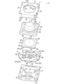
- FIG. 4 is an exploded perspective view of the same push switch.
- FIG. 5 is a plan view of a pressing body of the push switch;
- FIG. 6 is a bottom view of a pressing body of the push switch;
- FIG. 7 is a cross-sectional view showing a state in which the push switch is pressed.
- FIG. 8 is a cross-sectional view showing a state in which the push switch is pushed.
- the push switch 1 of this embodiment includes a case 7 , a fixed contact body 5 , a movable contact body 4 and a pressing body 3 .
- the case 7 has a concave portion 710 with an open top.
- the fixed contact body 5 has a fixed contact portion 51 provided on the bottom surface of the recess 710 .
- the movable contact body 4 has a movable contact portion 411 facing the fixed contact portion 51 .
- the movable contact body 4 is provided above the fixed contact body 5 .
- the pressing body 3 includes a pusher 31 , a support portion 32 and a connecting portion 33 .
- the pusher 31 is arranged above the movable contact body 4 .
- the pusher 31 pushes the movable contact body 4 toward the fixed contact body 5 in response to the pushing operation.
- the support portion 32 is supported by the case 7 .
- the connecting portion 33 is formed in a cylindrical shape surrounding the pusher 31 between the pusher 31 and the support portion 32 .
- the connecting portion 33 connects the pusher 31 and the support portion 32 .
- the connecting portion 33 is elastically deformed when the pusher 31 receives a pushing operation.
- the connecting portion 33 has a thin portion 331 and adjacent portions 332 and 333 adjacent to the thin portion 331 .
- the thin portion 331 is provided so as to surround the pusher 31 when viewed from at least one of the top and bottom. As shown in FIG. 2, the thickness T1 of the thin portion 331 is smaller than the thicknesses T2 and T3 of the adjacent portions 332 and 333 .
- the thickness T1 of the thin portion 331 is smaller than the thicknesses T2 and T3 of the adjacent portions 332 and 333, so that when the pusher 31 is pushed, the connecting portion 33 bends at the thin portion 331. It's easy to do.
- the connection portion 33 is likely to bend at the thin portion 331 not only when the pusher 31 is pushed directly downward but also when pushed obliquely downward.
- the bending portion of the connecting portion 33 tends to be limited to the thin portion 331 . Therefore, it is possible to reduce the possibility that the push switch 1 operates in an unstable manner. For example, it is possible to prevent the relationship between the magnitude of the pushing operation force and the stroke length from collapsing.
- the stroke length of the pusher 31 is the amount of movement of the pusher 31 from before the push operation is performed until the movable contact portion 411 contacts the fixed contact portion 51 after the push operation is performed.
- the terms “upper” and “lower” in the present disclosure merely represent relative directions of the push switch 1, and the direction of use of the push switch 1 is limited by “upper” and “lower” in the present disclosure. not intended to do so.
- the push switch 1 may be used in an orientation where "up” as used in the present disclosure is, for example, down, forward, backward, left or right.
- the direction in which the first terminals 54 and the second terminals 64, which will be described later, are arranged is defined as the “horizontal direction”, and the direction orthogonal to both the vertical direction and the horizontal direction (perpendicular to the plane of FIG. 1). direction) is defined as the front-rear direction.
- These regulations are not meant to limit the direction of use of the push switch 1 either.
- the push switch 1 is used for operation units of various devices such as personal digital assistants, in-vehicle devices, and home appliances.
- the push switch 1 is built in the housing of the device in a state of being mounted on a printed circuit board, for example.
- an operation button 10 (see FIG. 1) is arranged as an intermediate member at a position corresponding to the push switch 1 in the housing.
- the pusher 31 is indirectly operated via the operation button 10 .
- pressing the pusher 31 via the operation button 10 or directly pushing the pusher 31 is referred to as receiving a push operation on the pusher 31 .
- the push switch 1 includes a cover 2, a pressing body 3, a movable contact body 4, a fixed contact body 5, a conductive member 6, and a case 7, as shown in FIGS.
- the case 7 has a rectangular shape when viewed from above, and the cross section of FIG. 1 is a cross section along a diagonal line of the case 7 when viewed from above.
- "rectangle" is a concept that includes squares and rectangles.
- FIG. 2 is an enlarged view of the essential part of FIG.
- cover 2 is made of metal, for example. As shown in FIGS. 3 and 4, the cover 2 covers the case 7. As shown in FIGS.
- the cover 2 includes a cover body 21, a plurality of (two in FIG. 4) first projecting pieces 22, and a plurality of (two in FIG. 4) second projecting pieces 23.
- the shape of the cover body 21 is a rectangular plate.
- the thickness direction of the cover main body 21 extends along the vertical direction.
- the cover body 21 has a through hole 210 .
- the through hole 210 is provided in the central portion of the cover body 21 .
- the plane view shape of the through hole 210 is circular.
- the upper end of the pusher 31 protrudes upward from the cover body 21 through the through hole 210 .
- a first projecting piece 22 protrudes downward from each of the front and rear ends of the cover body 21 .
- the case 7 is held between the two first projecting pieces 22 . Thereby, the movement of the cover 2 in the front-rear direction with respect to the case 7 is restricted.
- the first projecting piece 22 has a plurality of hooking claws 221 (two in FIG. 4).
- the two hooking claws 221 are hooked on the case 7 .
- the cover 2 is thereby held by the case 7 .
- Second projecting pieces 23 protrude downward from the left and right ends of the cover body 21, respectively. Case 7 is held between two second projecting pieces 23 . This restricts the lateral movement of the cover 2 with respect to the case 7 .
- the pusher 3 includes a pusher 31, a support portion 32, a connecting portion 33, and an extension portion .
- the pressing body 3 has elasticity. Further, the pressing body 3 has electrical insulation.
- the pressing body 3 is made of elastomer.
- the pressing body 3 is made of synthetic rubber.
- the pusher 31, the support portion 32, the connecting portion 33, and the extension portion 34 of the pressing body 3 are integrally formed of synthetic rubber.
- the synthetic rubber for example, silicone rubber may be used.
- the pressing body 3 may be manufactured by, for example, injection molding, or may be manufactured by compression molding.
- the pusher 31 has a first portion 311 and a second portion 312 .
- the first portion 311 is a portion including the upper surface 31U of the pusher 31 .
- the first portion 311 is a portion that receives a pushing operation.
- the second portion 312 is a portion including the lower surface 31L of the pusher 31 .
- the second portion 312 is a portion that pushes the movable contact body 4 .
- the second portion 312 protrudes downward from the first portion 311 .
- the shape of the upper surface 31U of the pusher 31 is circular.
- the shape of the first portion 311 is a truncated cone.
- the diameter of the first portion 311 is shorter toward the upper side.
- the shape of the lower surface 31L of the pusher 31 is circular.
- the shape of the second portion 312 is a truncated cone. The diameter of the second portion 312 is longer toward the upper side.
- the diameter of the upper end of the second portion 312 is shorter than the diameter of the lower end of the first portion 311. That is, the maximum diameter of second portion 312 is shorter than the maximum diameter of first portion 311 . Also, the diameter of the lower surface 31L of the pusher 31 is shorter than the diameter of the upper surface 31U.
- the shape of the support portion 32 is a rectangular plate.
- the thickness direction of the support portion 32 extends along the vertical direction.
- the support portion 32 has an upper surface 32U and a lower surface 32L.
- the support part 32 is placed on the case 7.
- the support portion 32 is sandwiched and supported between the case 7 and the cover 2 . That is, the upper surface 32U of the support portion 32 is in contact with the cover 2, and the lower surface 32L is in contact with the case 7. As shown in FIG.
- the support portion 32 may be positioned between the case 7 and the cover 2 with the upper surface 32U of the support portion 32 separated from the cover 2 .
- the upper surface 32U of the support portion 32 may move upward and contact the cover 2 by the force of the pushing operation. This prevents the support portion 32 from being pulled toward the pusher 31 and the position of the support portion 32 from greatly fluctuating when the pusher 31 is pushed.
- the support part 32 has an opening 320 .
- the opening 320 is provided at the center of the support 32 .
- the connecting portion 33 is connected to the inner edge of the opening 320 of the support portion 32 . When viewed from above, the connecting portion 33 is arranged inside the inner edge of the opening 320 .
- the connecting portion 33 connects the pusher 31 and the support portion 32 .
- the shape of the connecting portion 33 is cylindrical.
- a second portion 312 of the pusher 31 is arranged inside the connecting portion 33 .
- the connecting part 33 having a tubular shape does not necessarily require that the connecting part 33 is continuous over the entire circumference in the circumferential direction, and a notch or the like may be present in a part of the connecting part 33 .
- the external shape of the connecting portion 33 is a truncated cone.
- the external shape of the configuration consisting of the connecting portion 33 and the first portion 311 of the pusher 31 is a truncated cone.
- the diameter of this configuration is shorter at the top.
- the extension part 34 protrudes downward from the lower end of the connecting part 33 .
- the extension 34 has an annular shape.
- the connecting portion 33 has a thin portion 331 and two adjacent portions 332 and 333 .
- the thin portion 331 is illustrated with dots.
- the adjacent portion 332 is provided above the thin portion 331 .
- the adjacent portion 333 is provided below the thin portion 331 .
- the thin portion 331 and adjacent portions 332 and 333 are cylindrical in shape.
- Thin portion 331 is seamlessly connected to adjacent portions 332 and 333 .
- a second portion 312 of the pusher 31 is arranged inside the thin portion 331 .
- the thin portion 331 is provided near the center of the connecting portion 33 in the vertical direction.
- the thin portion 331 is provided at a position aligned with the upper surface 32U (see FIG. 1) of the support portion 32 in a direction perpendicular to the vertical direction.
- the connecting portion 33 is connected to the pusher 31 at a portion above the thin portion 331 . Also, the connecting portion 33 is connected to the supporting portion 32 at a portion below the thin portion 331 .
- the thin portion 331 is a portion where the thickness is extremely small. That is, as shown in FIG. 2, the thickness T1 of the thin portion 331 is smaller than the thickness T2 of the adjacent portion 332 and the thickness T3 of the adjacent portion 333 .
- the thickness T1 of the thin portion 331 refers to the average thickness of the thin portion 331 .
- the thickness T2 of the adjacent portion 332 refers to the average thickness of the adjacent portion 332 .
- the thickness T3 of the adjacent portion 333 refers to the average thickness of the adjacent portion 333 .
- arrows indicating the thicknesses T1 to T3 are attached near the center of each of the thin portion 331 and adjacent portions 332 and 333 for convenience of illustration.
- the thickness of each portion of the adjacent portion 332 is smaller toward the bottom.
- the rate of decrease in thickness increases from the adjacent portion 332 to the thin portion 331 . That is, as shown in FIG. 2, in the cross section of the connecting portion 33, a line segment along the surface of the adjacent portion 332 and a line segment along the surface of the portion of the thin portion 331 near the adjacent portion 332 are different from each other. form an angle ⁇ 1.
- the thickness of each portion of the adjacent portion 332 may be substantially constant.
- each portion of the adjacent portion 333 is substantially constant in the present embodiment, the thickness of the adjacent portion 333 may differ depending on the portion, similarly to the adjacent portion 332 .
- the thickness of the adjacent portion 333 may be smaller toward the upper side. Further, when the surface of the connecting portion 33 is traced from the adjacent portion 333 to the thin portion 331 , the rate of decrease in thickness may increase from the adjacent portion 333 to the thin portion 331 .
- the connecting portion 33 has an outer recess 3311 on the outer surface of the thin portion 331 .
- the connecting portion 33 is recessed more than the adjacent portions 332 and 333 at the outer recess 3311 .
- the outer depression 3311 is provided over the entire circumference of the connecting portion 33 . That is, when viewed from above, the shape of the region provided with the outer depression 3311 is annular (more specifically, annular).
- the connecting portion 33 has an inner recess 3312 on the inner surface of the thin portion 331 .
- the connecting portion 33 is recessed more than the adjacent portions 332 and 333 at the inner recess 3312 .
- the inner depression 3312 is provided at a portion aligned with the outer depression 3311 in the thickness direction of the connecting portion 33 .
- the bottom surface of the inner depression 3312 and the bottom surface of the outer depression 3311 are the relationship between the back surface and the front surface.
- the inner recess 3312 is provided over the entire circumference of the connecting portion 33 . That is, when viewed from below, the shape of the region in which the inner depression 3312 is provided is annular (more specifically, annular).
- the shape of the region provided with the thin portion 331 is along the shape of the outer edge of the pusher 31.
- the area where the thin portion 331 is provided is indicated by dots, and the shape of the area where the thin portion 331 is provided corresponds to the shape of the pusher 31 . It follows the shape of the outer edge of the first portion 311 . More specifically, the shape of the region where the thin portion 331 is provided is concentric with the outer edge of the first portion 311 . Also, in FIG.
- the area where the thin portion 331 is provided (the area where the inner recess 3312 is provided) is indicated by a dot, and the shape of the area where the thin portion 331 is provided corresponds to the shape of the pusher 31 . It follows the shape of the outer edge of the second portion 312 . More specifically, the shape of the region where the thin portion 331 is provided is concentric with the outer edge of the second portion 312 .
- the depth of the outer depression 3311 is preferably 5% or more and 20% or less of the thickness T2 of the adjacent portion 332. It is also preferable that the depth of the outer depression 3311 is 5% or more and 20% or less of the thickness T3 of the adjacent portion 333 . Also, the depth of the inner recess 3312 is preferably 5% or more and 20% or less of the thickness T2 of the adjacent portion 332 . It is also preferable that the depth of the inner depression 3312 is 5% or more and 20% or less of the thickness T3 of the adjacent portion 333 .
- the thickness T2 of the adjacent portion 332 refers to the average thickness of the adjacent portion 332 .
- the thickness T3 of the adjacent portion 333 refers to the average thickness of the adjacent portion 333 .
- the depth of the outer depression 3311 when compared with the thickness T2, is the distance between the base point B2 of the thickness T2 on the outer surface of the connecting portion 33 and the most depressed portion B1 of the outer depression 3311. is defined to be equal to the distance D1 in the thickness direction of the connecting portion 33 between
- the depth of the outer depression 3311 when compared with the thickness T3, is the distance between the base point B3 of the thickness T3 on the outer surface of the connecting portion 33 and the most depressed portion B1 of the outer depression 3311. is defined to be equal to the distance D2 in the thickness direction of the connecting portion 33 between
- the depth of the inner recess 3312 when compared with the thickness T2, is the distance between the base point B5 of the thickness T2 on the inner surface of the connecting portion 33 and the deepest portion B4 of the inner recess 3312. is defined to be equal to the distance D3 in the thickness direction of the connecting portion 33 between
- the depth of the inner recess 3312 when compared with the thickness T3, is the distance between the base point B6 of the thickness T3 on the inner surface of the connecting portion 33 and the deepest portion B4 of the inner recess 3312. is defined to be equal to the distance D4 in the thickness direction of the connecting portion 33 between.
- the movable contact body 4 shown in FIGS. 1 and 4 has electrical conductivity.
- the movable contact body 4 is made of metal, for example.
- the movable contact body 4 is made of an elastic plate material.
- the movable contact body 4 is made of, for example, a metal plate such as stainless steel (SUS).
- the movable contact body 4 is composed of one leaf spring.
- the movable contact body 4 may be composed of a plurality of plate springs stacked on each other.
- the movable contact body 4 is a so-called metal dome.
- the movable contact body 4 is formed in a curved dome shape so that the central portion is convex upward.
- at least part of the lower surface of the movable contact body 4 is formed with a conductive film having electrical conductivity by, for example, gold (Au) plating or silver (Ag) plating.
- the movable contact body 4 includes a pressure receiving portion 41, a bending portion 42, an outer peripheral portion 43, and a plurality of (four in FIG. 4) supporting pieces 44.
- the pressure receiving portion 41 is provided in the central portion of the movable contact body 4 .
- the pressure receiving portion 41 is a portion to which force acts from the lower surface 31L of the pusher 31 . That is, when the pusher 31 is pressed and the pusher 31 pushes the pressure receiving portion 41 downward, the movable contact body 4 is elastically deformed so that the pressure receiving portion 41 moves downward.
- the lower surface of the pressure receiving portion 41 functions as a movable contact portion 411. That is, the pressure receiving portion 41 has a movable contact portion 411 .
- the pusher 31 is pushed, the movable contact portion 411 comes into contact with the fixed contact portion 51 .
- the bending portion 42 is provided around the pressure receiving portion 41 .
- the area occupied by the bending portion 42 is an annular area.
- the outer peripheral portion 43 is provided around the bending portion 42 .
- the outer peripheral portion 43 has an annular shape.
- a plurality of support pieces 44 protrude outward from the outer peripheral portion 43 .
- the plurality of supporting pieces 44 are placed on the conductive member 6 embedded in the concave portion 710 of the case 7 . Thereby, the movable contact body 4 and the conductive member 6 are electrically connected.
- the bending portion 42 deforms (bends) and the movable contact body 4 bends downward.
- the movable contact body 4 deforms into a dome shape in which the central portion of the movable contact body 4 protrudes downward.
- the load acting on the pusher 31 from the movable contact body 4 is reduced.
- the movable contact body 4 is configured to perform a reversal operation according to the magnitude of the operating force applied to the pusher 31 .
- the movable contact portion 411 and the fixed contact portion 51 constitute the contact portion C1.
- the contact portion C1 is switched from off to on when the pressure receiving portion 41 is pushed in a direction (downward) approaching the fixed contact portion 51 and the movable contact body 4 is deformed. Specifically, when the pusher 31 is not pressed (the state shown in FIG. 1), the movable contact portion 411 is separated from the fixed contact portion 51, so the contact portion C1 is off. On the other hand, when the pusher 31 is pushed, the movable contact portion 411 comes into contact with the fixed contact portion 51 (see FIG. 7), so that the contact portion C1 is turned on. When the pushing operation is released, the movable contact body 4 is elastically restored and the contact portion C1 is turned off.
- the fixed contact body 5 shown in FIGS. 1 and 4 has electrical conductivity.
- the fixed contact body 5 is made of a metal plate. More specifically, the fixed contact body 5 is made of a single metal plate.
- the fixed contact body 5 is embedded in the bottom surface of the recess 710 of the case 7 .
- the fixed contact body 5 and the case 7 are integrated by insert molding. That is, the case 7 is insert-molded with the fixed contact body 5 as an insert product.
- the fixed contact body 5 has a fixed contact portion 51 , a base portion 52 , a connection portion 53 and a first terminal 54 .
- the base 52 is embedded in the bottom surface of the recess 710 of the case 7.
- the fixed contact portion 51 protrudes upward from the upper surface of the base portion 52 .
- a movable contact portion 411 is arranged above the fixed contact portion 51 . That is, the fixed contact portion 51 faces the movable contact portion 411 .
- the connecting portion 53 is provided between the base portion 52 and the first terminal 54 and connects the base portion 52 and the first terminal 54 .
- the connection portion 53 is embedded in the bottom surface of the recess 710 of the case 7 .
- the first terminal 54 protrudes from the side surface of the case 7 .
- the conductive member 6 shown in FIGS. 1 and 4 has conductivity.
- the conductive member 6 is composed of a metal plate. More specifically, the conductive member 6 is made of a single metal plate.
- the conductive member 6 is embedded in the bottom surface of the recess 710 of the case 7 .
- the conductive member 6 and the case 7 are integrated by insert molding. That is, the case 7 is insert-molded with the conductive member 6 as an insert.
- the conductive member 6 has a plurality of (four in FIG. 4) exposed portions 61, a plurality of (two in FIG. 4) first connecting portions 62, a second connecting portion 63, and a second terminal 64. .
- the plurality of exposed portions 61 are exposed in the space forming the recessed portion 710 of the case 7 .
- the plurality of exposed portions 61 are in contact with the plurality of support pieces 44 of the movable contact body 4 .
- the conductive member 6 is electrically connected to the movable contact body 4 .
- the conductive member 6 supports the movable contact body 4 at a plurality of exposed portions 61 .
- the plurality (four) of exposed portions 61 may be distinguished and called exposed portions 61a, 61b, 61c, and 61d, respectively.
- One of the two first connection portions 62 connects the exposed portions 61a and 61b.
- the other of the two first connection portions 62 connects the exposed portions 61c and 61d.
- the second connection portion 63 connects the exposed portions 61 a and 61 c and the second terminal 64 .
- the second terminal 64 protrudes from the side surface of the case 7 .
- the second terminal 64 is provided on the side opposite to the first terminal 54 .
- the first terminal 54 and the second terminal 64 are mechanically coupled and electrically connected to conductive members on a printed circuit board, for example, by soldering.
- the contact portion C1 When the contact portion C1 is off, the first terminal 54 and the second terminal 64 are not electrically connected because the fixed contact body 5 and the conductive member 6 are electrically insulated.
- the contact portion C1 When the contact portion C1 is on, the fixed contact body 5 and the conductive member 6 are electrically connected via the movable contact body 4, so that the first terminal 54 and the second terminal 64 are electrically connected.
- the case 7 includes a case body 71, a plurality (four in this embodiment) of pedestals 72, and a plurality (four in this embodiment) of a protrusion 73;
- the case main body 71, the plurality of pedestals 72, and the plurality of projections 73 are integrally formed.
- the case 7 is made of synthetic resin.
- the shape of the case main body 71 is rectangular parallelepiped.
- a concave portion 710 is formed in the upper surface of the case main body 71 .
- the shape of the recess 710 is rectangular.
- a pedestal 72 is provided at each of the four corners of the concave portion 710 viewed from above. Each pedestal 72 protrudes upward from the bottom surface of the recess 710 . Each pedestal portion 72 is provided with an exposed portion 61 .
- the case 7 accommodates the movable contact body 4 in the concave portion 710 .
- the support part 32 of the pressing body 3 is placed on the periphery of the concave portion 710 on the upper surface of the case main body 71 .
- Two protrusions 73 protrude from the front surface of the case body 71 .
- Two protrusions 73 protrude from the rear surface of the case main body 71 .
- the first projecting piece 22 of the cover 2 is hooked on each projection 73 .
- the movable contact body 4 deforms into a curved dome shape so that the central portion (pressure receiving portion 41) is convex downward.
- An operator who presses the push switch 1 is given a click feeling as the movable contact member 4 deforms.
- the movable contact body 4 is deformed as described above, the movable contact portion 411 formed on the lower surface of the movable contact body 4 comes into contact with the fixed contact portion 51 as shown in FIG.
- the connecting portion 33 of the pusher 3 is elastically deformed. Specifically, as shown in FIG. 7, the connecting portion 33 is deformed such that a portion of the connecting portion 33 protrudes downward.
- the connecting portion 33 returns to its original shape due to the restoring force of the connecting portion 33, and the pusher 31 returns to its original position (see FIG. 1).
- the connecting portion 33 Since the connecting portion 33 has the thin portion 331, there is a high possibility that the connecting portion 33 will be deformed so as to protrude downward at the position where the thin portion 331 is provided, as shown in FIG. That is, there is a high possibility that the connecting portion 33 will bend at the thin portion 331 . Therefore, it is possible to reduce the possibility that the connecting portion 33 may be bent at various locations. That is, it is possible to reduce the possibility that the push switch 1 will operate in an unstable manner. For example, it is possible to prevent the relationship between the magnitude of the pushing force applied to the pusher 31 and the stroke length of the pusher 31 from collapsing.
- the bent portion may be bent. It may be easy to bend in places. If the plurality of push switches 1 are creased at different locations in the connecting portion 33, the plurality of push switches 1 may have different characteristics. For example, a situation may occur in which the relationship between the magnitude of the pushing operation force on the pusher 31 and the stroke length of the pusher 31 differs for each push switch 1 . That is, the quality of the push switch 1 may vary. In particular, when the pusher 31 is pressed for the first time after manufacturing, if the direction of the pressing operation is oblique, the connecting portion 33 may bend at a location different from the location where it should originally bend.
- the push switch 1 of the present embodiment when the pusher 31 is pushed for the first time after manufacturing, there is a high possibility that the connecting portion 33 will bend at the thin portion 331 . Therefore, it is possible to reduce the possibility that the quality of the push switch 1 varies.
- the thin portion 331 When the thin portion 331 is not provided in the connection portion 33 (that is, when the thickness T1 of the thin portion 331 is equal to the thicknesses T2 and T3 of the adjacent portions 332 and 333), the thin portion 331 preferably has a pusher It is provided at a portion that bends when 31 is pushed downward. As a result, the characteristics of the push switch 1 can be brought closer to the characteristics when an equivalent product without the thin portion 331 is normally used.
- the connecting portion 33 includes only one thin portion 331 .
- the connecting portion 33 is likely to bend at a fixed location.
- a portion including the plurality of regions arranged in the circumferential direction is defined as one thin portion 331.
- the case where a plurality of regions having a minimum thickness are arranged in the circumferential direction of the connecting portion 33 in the connecting portion 33 means, for example, at least one of the outer depression 3311 and the inner depression 3312 along the circumferential direction of the connecting portion 33. is provided in the form of perforations.
- the shape of each configuration described in the embodiment is an example and can be changed.
- the shape of the connecting portion 33 is not limited to a cylindrical shape, and may be, for example, a rectangular tube shape.
- the shape of the first portion 311 of the pusher 31 is not limited to a truncated cone shape, and may be, for example, a truncated pyramid shape, a columnar shape, or a prismatic shape.
- the shape of the second portion 312 of the pusher 31 is not limited to a truncated cone shape, and may be, for example, a truncated pyramid shape, a columnar shape, or a prismatic shape.
- the connecting portion 33 protrudes outward and downward from the pusher 31 .
- the connecting portion 33 may, for example, protrude outward from the pusher 31 on a plane perpendicular to the vertical direction.
- Only one of the outer recess 3311 and the inner recess 3312 may be provided in the thin portion 331 .
- the outer recess 3311 may not be provided over the entire circumference of the connecting portion 33 .
- the outer depressions 3311 may be provided only in some of the dotted regions in FIG.
- the outer depression 3311 may be interrupted at multiple locations.
- the outer depression 3311 may be provided in a perforation pattern along the circumferential direction of the connecting portion 33 .
- the inner recess 3312 may not be provided over the entire circumference of the connecting portion 33 .
- the inner depressions 3312 may be provided only in some of the dotted areas in FIG.
- the inner recess 3312 may be interrupted at multiple locations.
- inner recesses 3312 may be provided in a perforation pattern along the circumferential direction of the connecting portion 33 .
- At least one of the outer recess 3311 and the inner recess 3312 may not be smoothly connected to the surface of the adjacent portion 332 as in the embodiment.
- at least one of the outer recess 3311 and the inner recess 3312 has a side surface and a bottom surface, the side surface being bent with respect to the surface of the adjacent portion 332 at a predetermined angle.
- at least one of the outer recess 3311 and the inner recess 3312 may be formed to have a wedge-shaped cross section.
- At least one of the outer recess 3311 and the inner recess 3312 may not smoothly connect with the surface of the adjacent portion 333 as in the embodiment.
- the pressing body 3 may be formed by combining a plurality of members such as connecting a plurality of members.
- extension part 34 is not an essential component in the pressing body 3 .
- the stroke length of the push switch 1 can be set as appropriate.
- the push switch 1 may be a short stroke type with a relatively short stroke length, a long stroke type with a relatively long stroke length, or a middle stroke type that falls between the short stroke type and the long stroke type.
- the push switch 1 is not limited to being used in the operation section of the device and operated by a person, and may be used for detecting the position of the device, for example. In this case, by moving the device to a predetermined position, the pusher 31 of the push switch 1 installed at the predetermined position is pushed, and the push switch 1 outputs a signal.
- the conductive member 6 may be in contact with the movable contact body 4 at locations other than the plurality of supporting pieces 44 of the movable contact body 4 .
- a push switch (1) includes a case (7), a fixed contact body (5), a movable contact body (4), and a pressing body (3).
- the case (7) has a concave portion (710) with an upper opening.
- the fixed contact body (5) has a fixed contact portion (51) provided on the bottom surface of the recess (710).
- the movable contact body (4) has a movable contact portion (411) facing the fixed contact portion (51).
- the movable contact body (4) is provided above the fixed contact body (5).
- the pressing body (3) includes a pressing element (31), a supporting portion (32), and a connecting portion (33).
- a pusher (31) is arranged above the movable contact body (4).
- the pusher (31) pushes the movable contact body (4) toward the fixed contact body (5) in response to the pushing operation.
- the support (32) is supported by the case (7).
- the connecting part (33) is formed in a cylindrical shape surrounding the pusher (31) between the pusher (31) and the support part (32).
- the connecting portion (33) connects the pusher (31) and the support portion (32).
- the connecting portion (33) is elastically deformed when the pusher (31) is pushed.
- the connecting portion (33) has a thin portion (331) and adjacent portions (332, 333) adjacent to the thin portion (331).
- the thin portion (331) is provided so as to surround the pusher (31) when viewed from at least one of the top and bottom.
- the thickness (T1) of the thin portion (331) is smaller than the thickness (T2, T3) of the adjacent portions (332, 333).
- the thickness (T1) of the thin portion (331) is smaller than the thickness (T2, T3) of the adjacent portions (332, 333).
- the connecting portion (33) is likely to bend at the thin portion (331).
- the connection part (33) is likely to bend at the thin part (331) not only when the pusher (31) is pushed straight down but also when pushed obliquely downward.
- the bending portion of the connecting portion (33) tends to be limited to the thin portion (331). Therefore, it is possible to reduce the possibility that the push switch (1) operates in an unstable manner. For example, it is possible to prevent the relationship between the magnitude of the pushing operation force and the stroke length from collapsing.
- the connecting portion (33) has an outer recess that is recessed more than the adjacent portions (332, 333) on the outer surface of the thin portion (331). (3311).
- the outer recess (3311) is provided over the entire circumference of the connecting portion (33).
- the connecting portion (33) is reduced to the thin portion (331).
- the depth of the outer recess (3311) is 5 times the thickness (T2, T3) of the adjacent portions (332, 333). % or more and 20% or less.
- connection portion (33) is thinner than when the depth of the outer recess (3311) is less than 5% of the thickness (T2, T3) of the adjacent portions (332, 333). It is easy to bend at the part (331). Moreover, compared to the case where the depth of the outer recess (3311) is greater than 20% of the thickness (T2, T3) of the adjacent parts (332, 333), the strength of the connecting part (33) can be increased.
- the connecting portion (33) is provided on the inner surface of the thin portion (331) and adjacent portions (332, 333). ) has an inner recess (3312) that is recessed than the .
- the inner depression (3312) is provided over the entire circumference of the connecting portion (33) in the fifth aspect.
- the connecting portion (33) is reduced to the thin portion (331). ).
- the depth of the inner recess (3312) is 5 times the thickness (T2, T3) of the adjacent portions (332, 333). % or more and 20% or less.
- connection portion (33) is thinner than when the depth of the inner recess (3312) is less than 5% of the thickness (T2, T3) of the adjacent portions (332, 333). It is easy to bend at the part (331). Moreover, the strength of the connecting portion (33) can be increased compared to the case where the depth of the inner recess (3312) is greater than 20% of the thickness (T2, T3) of the adjacent portions (332, 333).
- the shape of the region provided with the thin portion (331) when viewed from at least one of the top and bottom follows the shape of the outer edge of the pusher (31).
- the force of the push operation to the pusher (31) is easily transmitted to the thin portion (331) evenly.
- Configurations other than the first aspect are not essential configurations for the push switch (1) and can be omitted as appropriate.
Landscapes
- Push-Button Switches (AREA)
Priority Applications (3)
| Application Number | Priority Date | Filing Date | Title |
|---|---|---|---|
| EP22898183.3A EP4439606A4 (en) | 2021-11-26 | 2022-08-17 | PRESSURE SWITCH |
| CN202280067608.9A CN118056253A (zh) | 2021-11-26 | 2022-08-17 | 推压开关 |
| JP2023563518A JPWO2023095398A1 (https=) | 2021-11-26 | 2022-08-17 |
Applications Claiming Priority (2)
| Application Number | Priority Date | Filing Date | Title |
|---|---|---|---|
| JP2021192487 | 2021-11-26 | ||
| JP2021-192487 | 2021-11-26 |
Publications (1)
| Publication Number | Publication Date |
|---|---|
| WO2023095398A1 true WO2023095398A1 (ja) | 2023-06-01 |
Family
ID=86539113
Family Applications (1)
| Application Number | Title | Priority Date | Filing Date |
|---|---|---|---|
| PCT/JP2022/031023 Ceased WO2023095398A1 (ja) | 2021-11-26 | 2022-08-17 | プッシュスイッチ |
Country Status (4)
| Country | Link |
|---|---|
| EP (1) | EP4439606A4 (https=) |
| JP (1) | JPWO2023095398A1 (https=) |
| CN (1) | CN118056253A (https=) |
| WO (1) | WO2023095398A1 (https=) |
Cited By (1)
| Publication number | Priority date | Publication date | Assignee | Title |
|---|---|---|---|---|
| JP7595848B1 (ja) | 2024-03-26 | 2024-12-09 | Smk株式会社 | キートップ及びスイッチ |
Citations (3)
| Publication number | Priority date | Publication date | Assignee | Title |
|---|---|---|---|---|
| JP2006120397A (ja) * | 2004-10-20 | 2006-05-11 | Matsushita Electric Ind Co Ltd | プッシュオンスイッチ |
| JP2018067401A (ja) * | 2016-10-17 | 2018-04-26 | 積水ポリマテック株式会社 | コンタクトラバー |
| WO2019225635A1 (ja) | 2018-05-24 | 2019-11-28 | パナソニックIpマネジメント株式会社 | プッシュスイッチ |
-
2022
- 2022-08-17 JP JP2023563518A patent/JPWO2023095398A1/ja active Pending
- 2022-08-17 WO PCT/JP2022/031023 patent/WO2023095398A1/ja not_active Ceased
- 2022-08-17 EP EP22898183.3A patent/EP4439606A4/en not_active Withdrawn
- 2022-08-17 CN CN202280067608.9A patent/CN118056253A/zh active Pending
Patent Citations (3)
| Publication number | Priority date | Publication date | Assignee | Title |
|---|---|---|---|---|
| JP2006120397A (ja) * | 2004-10-20 | 2006-05-11 | Matsushita Electric Ind Co Ltd | プッシュオンスイッチ |
| JP2018067401A (ja) * | 2016-10-17 | 2018-04-26 | 積水ポリマテック株式会社 | コンタクトラバー |
| WO2019225635A1 (ja) | 2018-05-24 | 2019-11-28 | パナソニックIpマネジメント株式会社 | プッシュスイッチ |
Non-Patent Citations (1)
| Title |
|---|
| See also references of EP4439606A4 |
Cited By (1)
| Publication number | Priority date | Publication date | Assignee | Title |
|---|---|---|---|---|
| JP7595848B1 (ja) | 2024-03-26 | 2024-12-09 | Smk株式会社 | キートップ及びスイッチ |
Also Published As
| Publication number | Publication date |
|---|---|
| EP4439606A1 (en) | 2024-10-02 |
| EP4439606A4 (en) | 2025-03-19 |
| JPWO2023095398A1 (https=) | 2023-06-01 |
| CN118056253A (zh) | 2024-05-17 |
Similar Documents
| Publication | Publication Date | Title |
|---|---|---|
| EP0224006B1 (en) | Pushbutton switches using dome springs | |
| KR20060055582A (ko) | 돔 접점 및 그것을 사용한 다단동작 전기 스위치 | |
| TWI616916B (zh) | 按鈕開關以及可動接點構件 | |
| CN215451206U (zh) | 可动构件以及输入装置 | |
| JP2010135319A (ja) | 多段動作スイッチ | |
| WO2023095398A1 (ja) | プッシュスイッチ | |
| JP7365645B2 (ja) | プッシュスイッチ | |
| EP1037226B1 (en) | Push switch | |
| TW201112289A (en) | Push-button switch | |
| JP2024151967A (ja) | プッシュスイッチ | |
| JP7519624B2 (ja) | プッシュスイッチ | |
| JP7369206B2 (ja) | プッシュスイッチの押圧機構、及び、プッシュスイッチ | |
| US11355295B2 (en) | Push switch | |
| JP5160484B2 (ja) | 高荷重スイッチ | |
| JP2026023897A (ja) | プッシュスイッチ | |
| KR100405994B1 (ko) | 푸쉬버튼 스위치 | |
| JP2010153159A (ja) | 多方向スライド式スイッチ | |
| WO2023248701A1 (ja) | プッシュスイッチ | |
| WO2025216123A1 (ja) | プッシュスイッチ | |
| JP4457097B2 (ja) | 横押し型プッシュスイッチ | |
| JP4332543B2 (ja) | 横押し型プッシュスイッチ | |
| WO2025225397A1 (ja) | プッシュスイッチ | |
| JP3180966U (ja) | プッシュスイッチ | |
| JP7308404B2 (ja) | プッシュスイッチ | |
| JP2005032487A (ja) | 押釦スイッチ用反転ばね及びこれを用いた押釦スイッチ |
Legal Events
| Date | Code | Title | Description |
|---|---|---|---|
| 121 | Ep: the epo has been informed by wipo that ep was designated in this application |
Ref document number: 22898183 Country of ref document: EP Kind code of ref document: A1 |
|
| WWE | Wipo information: entry into national phase |
Ref document number: 202280067608.9 Country of ref document: CN |
|
| ENP | Entry into the national phase |
Ref document number: 2023563518 Country of ref document: JP Kind code of ref document: A |
|
| WWE | Wipo information: entry into national phase |
Ref document number: 2022898183 Country of ref document: EP |
|
| NENP | Non-entry into the national phase |
Ref country code: DE |
|
| ENP | Entry into the national phase |
Ref document number: 2022898183 Country of ref document: EP Effective date: 20240626 |
|
| WWW | Wipo information: withdrawn in national office |
Ref document number: 2022898183 Country of ref document: EP |