WO2023095281A1 - 車両の制御方法及び車両の制御装置 - Google Patents
車両の制御方法及び車両の制御装置 Download PDFInfo
- Publication number
- WO2023095281A1 WO2023095281A1 PCT/JP2021/043374 JP2021043374W WO2023095281A1 WO 2023095281 A1 WO2023095281 A1 WO 2023095281A1 JP 2021043374 W JP2021043374 W JP 2021043374W WO 2023095281 A1 WO2023095281 A1 WO 2023095281A1
- Authority
- WO
- WIPO (PCT)
- Prior art keywords
- vehicle
- battery
- generator
- engine
- rotation speed
- Prior art date
- Legal status (The legal status is an assumption and is not a legal conclusion. Google has not performed a legal analysis and makes no representation as to the accuracy of the status listed.)
- Ceased
Links
Images




Classifications
-
- B—PERFORMING OPERATIONS; TRANSPORTING
- B60—VEHICLES IN GENERAL
- B60W—CONJOINT CONTROL OF VEHICLE SUB-UNITS OF DIFFERENT TYPE OR DIFFERENT FUNCTION; CONTROL SYSTEMS SPECIALLY ADAPTED FOR HYBRID VEHICLES; ROAD VEHICLE DRIVE CONTROL SYSTEMS FOR PURPOSES NOT RELATED TO THE CONTROL OF A PARTICULAR SUB-UNIT
- B60W30/00—Purposes of road vehicle drive control systems not related to the control of a particular sub-unit, e.g. of systems using conjoint control of vehicle sub-units
- B60W30/18—Propelling the vehicle
- B60W30/188—Controlling power parameters of the driveline, e.g. determining the required power
-
- B—PERFORMING OPERATIONS; TRANSPORTING
- B60—VEHICLES IN GENERAL
- B60W—CONJOINT CONTROL OF VEHICLE SUB-UNITS OF DIFFERENT TYPE OR DIFFERENT FUNCTION; CONTROL SYSTEMS SPECIALLY ADAPTED FOR HYBRID VEHICLES; ROAD VEHICLE DRIVE CONTROL SYSTEMS FOR PURPOSES NOT RELATED TO THE CONTROL OF A PARTICULAR SUB-UNIT
- B60W20/00—Control systems specially adapted for hybrid vehicles
- B60W20/10—Controlling the power contribution of each of the prime movers to meet required power demand
- B60W20/13—Controlling the power contribution of each of the prime movers to meet required power demand in order to stay within battery power input or output limits; in order to prevent overcharging or battery depletion
-
- B—PERFORMING OPERATIONS; TRANSPORTING
- B60—VEHICLES IN GENERAL
- B60K—ARRANGEMENT OR MOUNTING OF PROPULSION UNITS OR OF TRANSMISSIONS IN VEHICLES; ARRANGEMENT OR MOUNTING OF PLURAL DIVERSE PRIME-MOVERS IN VEHICLES; AUXILIARY DRIVES FOR VEHICLES; INSTRUMENTATION OR DASHBOARDS FOR VEHICLES; ARRANGEMENTS IN CONNECTION WITH COOLING, AIR INTAKE, GAS EXHAUST OR FUEL SUPPLY OF PROPULSION UNITS IN VEHICLES
- B60K6/00—Arrangement or mounting of plural diverse prime-movers for mutual or common propulsion, e.g. hybrid propulsion systems comprising electric motors and internal combustion engines
- B60K6/20—Arrangement or mounting of plural diverse prime-movers for mutual or common propulsion, e.g. hybrid propulsion systems comprising electric motors and internal combustion engines the prime-movers consisting of electric motors and internal combustion engines, e.g. HEVs
- B60K6/42—Arrangement or mounting of plural diverse prime-movers for mutual or common propulsion, e.g. hybrid propulsion systems comprising electric motors and internal combustion engines the prime-movers consisting of electric motors and internal combustion engines, e.g. HEVs characterised by the architecture of the hybrid electric vehicle
- B60K6/46—Series type
-
- B—PERFORMING OPERATIONS; TRANSPORTING
- B60—VEHICLES IN GENERAL
- B60L—PROPULSION OF ELECTRICALLY-PROPELLED VEHICLES; SUPPLYING ELECTRIC POWER FOR AUXILIARY EQUIPMENT OF ELECTRICALLY-PROPELLED VEHICLES; ELECTRODYNAMIC BRAKE SYSTEMS FOR VEHICLES IN GENERAL; MAGNETIC SUSPENSION OR LEVITATION FOR VEHICLES; MONITORING OPERATING VARIABLES OF ELECTRICALLY-PROPELLED VEHICLES; ELECTRIC SAFETY DEVICES FOR ELECTRICALLY-PROPELLED VEHICLES
- B60L50/00—Electric propulsion with power supplied within the vehicle
- B60L50/50—Electric propulsion with power supplied within the vehicle using propulsion power supplied by batteries or fuel cells
- B60L50/60—Electric propulsion with power supplied within the vehicle using propulsion power supplied by batteries or fuel cells using power supplied by batteries
- B60L50/61—Electric propulsion with power supplied within the vehicle using propulsion power supplied by batteries or fuel cells using power supplied by batteries by batteries charged by engine-driven generators, e.g. series hybrid electric vehicles
-
- B—PERFORMING OPERATIONS; TRANSPORTING
- B60—VEHICLES IN GENERAL
- B60L—PROPULSION OF ELECTRICALLY-PROPELLED VEHICLES; SUPPLYING ELECTRIC POWER FOR AUXILIARY EQUIPMENT OF ELECTRICALLY-PROPELLED VEHICLES; ELECTRODYNAMIC BRAKE SYSTEMS FOR VEHICLES IN GENERAL; MAGNETIC SUSPENSION OR LEVITATION FOR VEHICLES; MONITORING OPERATING VARIABLES OF ELECTRICALLY-PROPELLED VEHICLES; ELECTRIC SAFETY DEVICES FOR ELECTRICALLY-PROPELLED VEHICLES
- B60L58/00—Methods or circuit arrangements for monitoring or controlling batteries or fuel cells, specially adapted for electric vehicles
- B60L58/10—Methods or circuit arrangements for monitoring or controlling batteries or fuel cells, specially adapted for electric vehicles for monitoring or controlling batteries
- B60L58/24—Methods or circuit arrangements for monitoring or controlling batteries or fuel cells, specially adapted for electric vehicles for monitoring or controlling batteries for controlling the temperature of batteries
- B60L58/27—Methods or circuit arrangements for monitoring or controlling batteries or fuel cells, specially adapted for electric vehicles for monitoring or controlling batteries for controlling the temperature of batteries by heating
-
- B—PERFORMING OPERATIONS; TRANSPORTING
- B60—VEHICLES IN GENERAL
- B60W—CONJOINT CONTROL OF VEHICLE SUB-UNITS OF DIFFERENT TYPE OR DIFFERENT FUNCTION; CONTROL SYSTEMS SPECIALLY ADAPTED FOR HYBRID VEHICLES; ROAD VEHICLE DRIVE CONTROL SYSTEMS FOR PURPOSES NOT RELATED TO THE CONTROL OF A PARTICULAR SUB-UNIT
- B60W10/00—Conjoint control of vehicle sub-units of different type or different function
- B60W10/04—Conjoint control of vehicle sub-units of different type or different function including control of propulsion units
- B60W10/06—Conjoint control of vehicle sub-units of different type or different function including control of propulsion units including control of combustion engines
-
- B—PERFORMING OPERATIONS; TRANSPORTING
- B60—VEHICLES IN GENERAL
- B60W—CONJOINT CONTROL OF VEHICLE SUB-UNITS OF DIFFERENT TYPE OR DIFFERENT FUNCTION; CONTROL SYSTEMS SPECIALLY ADAPTED FOR HYBRID VEHICLES; ROAD VEHICLE DRIVE CONTROL SYSTEMS FOR PURPOSES NOT RELATED TO THE CONTROL OF A PARTICULAR SUB-UNIT
- B60W10/00—Conjoint control of vehicle sub-units of different type or different function
- B60W10/04—Conjoint control of vehicle sub-units of different type or different function including control of propulsion units
- B60W10/08—Conjoint control of vehicle sub-units of different type or different function including control of propulsion units including control of electric propulsion units, e.g. motors or generators
-
- B—PERFORMING OPERATIONS; TRANSPORTING
- B60—VEHICLES IN GENERAL
- B60W—CONJOINT CONTROL OF VEHICLE SUB-UNITS OF DIFFERENT TYPE OR DIFFERENT FUNCTION; CONTROL SYSTEMS SPECIALLY ADAPTED FOR HYBRID VEHICLES; ROAD VEHICLE DRIVE CONTROL SYSTEMS FOR PURPOSES NOT RELATED TO THE CONTROL OF A PARTICULAR SUB-UNIT
- B60W10/00—Conjoint control of vehicle sub-units of different type or different function
- B60W10/24—Conjoint control of vehicle sub-units of different type or different function including control of energy storage means
- B60W10/26—Conjoint control of vehicle sub-units of different type or different function including control of energy storage means for electrical energy, e.g. batteries or capacitors
-
- B—PERFORMING OPERATIONS; TRANSPORTING
- B60—VEHICLES IN GENERAL
- B60L—PROPULSION OF ELECTRICALLY-PROPELLED VEHICLES; SUPPLYING ELECTRIC POWER FOR AUXILIARY EQUIPMENT OF ELECTRICALLY-PROPELLED VEHICLES; ELECTRODYNAMIC BRAKE SYSTEMS FOR VEHICLES IN GENERAL; MAGNETIC SUSPENSION OR LEVITATION FOR VEHICLES; MONITORING OPERATING VARIABLES OF ELECTRICALLY-PROPELLED VEHICLES; ELECTRIC SAFETY DEVICES FOR ELECTRICALLY-PROPELLED VEHICLES
- B60L2240/00—Control parameters of input or output; Target parameters
- B60L2240/40—Drive Train control parameters
- B60L2240/54—Drive Train control parameters related to batteries
- B60L2240/545—Temperature
-
- B—PERFORMING OPERATIONS; TRANSPORTING
- B60—VEHICLES IN GENERAL
- B60W—CONJOINT CONTROL OF VEHICLE SUB-UNITS OF DIFFERENT TYPE OR DIFFERENT FUNCTION; CONTROL SYSTEMS SPECIALLY ADAPTED FOR HYBRID VEHICLES; ROAD VEHICLE DRIVE CONTROL SYSTEMS FOR PURPOSES NOT RELATED TO THE CONTROL OF A PARTICULAR SUB-UNIT
- B60W2510/00—Input parameters relating to a particular sub-units
- B60W2510/24—Energy storage means
- B60W2510/242—Energy storage means for electrical energy
- B60W2510/244—Charge state
-
- B—PERFORMING OPERATIONS; TRANSPORTING
- B60—VEHICLES IN GENERAL
- B60W—CONJOINT CONTROL OF VEHICLE SUB-UNITS OF DIFFERENT TYPE OR DIFFERENT FUNCTION; CONTROL SYSTEMS SPECIALLY ADAPTED FOR HYBRID VEHICLES; ROAD VEHICLE DRIVE CONTROL SYSTEMS FOR PURPOSES NOT RELATED TO THE CONTROL OF A PARTICULAR SUB-UNIT
- B60W2510/00—Input parameters relating to a particular sub-units
- B60W2510/24—Energy storage means
- B60W2510/242—Energy storage means for electrical energy
- B60W2510/246—Temperature
-
- B—PERFORMING OPERATIONS; TRANSPORTING
- B60—VEHICLES IN GENERAL
- B60W—CONJOINT CONTROL OF VEHICLE SUB-UNITS OF DIFFERENT TYPE OR DIFFERENT FUNCTION; CONTROL SYSTEMS SPECIALLY ADAPTED FOR HYBRID VEHICLES; ROAD VEHICLE DRIVE CONTROL SYSTEMS FOR PURPOSES NOT RELATED TO THE CONTROL OF A PARTICULAR SUB-UNIT
- B60W2710/00—Output or target parameters relating to a particular sub-units
- B60W2710/06—Combustion engines, Gas turbines
- B60W2710/0644—Engine speed
-
- B—PERFORMING OPERATIONS; TRANSPORTING
- B60—VEHICLES IN GENERAL
- B60W—CONJOINT CONTROL OF VEHICLE SUB-UNITS OF DIFFERENT TYPE OR DIFFERENT FUNCTION; CONTROL SYSTEMS SPECIALLY ADAPTED FOR HYBRID VEHICLES; ROAD VEHICLE DRIVE CONTROL SYSTEMS FOR PURPOSES NOT RELATED TO THE CONTROL OF A PARTICULAR SUB-UNIT
- B60W2710/00—Output or target parameters relating to a particular sub-units
- B60W2710/08—Electric propulsion units
- B60W2710/083—Torque
-
- Y—GENERAL TAGGING OF NEW TECHNOLOGICAL DEVELOPMENTS; GENERAL TAGGING OF CROSS-SECTIONAL TECHNOLOGIES SPANNING OVER SEVERAL SECTIONS OF THE IPC; TECHNICAL SUBJECTS COVERED BY FORMER USPC CROSS-REFERENCE ART COLLECTIONS [XRACs] AND DIGESTS
- Y02—TECHNOLOGIES OR APPLICATIONS FOR MITIGATION OR ADAPTATION AGAINST CLIMATE CHANGE
- Y02T—CLIMATE CHANGE MITIGATION TECHNOLOGIES RELATED TO TRANSPORTATION
- Y02T10/00—Road transport of goods or passengers
- Y02T10/60—Other road transportation technologies with climate change mitigation effect
- Y02T10/62—Hybrid vehicles
Definitions
- the present invention relates to a vehicle control method and a vehicle control device.
- JP2004-300957A discloses a technology for performing feedback control so that the engine speed reaches a target speed when the engine is idling.
- a generator is connected to the output shaft of the engine, and if the actual engine speed is higher than the target speed, the generator is controlled so as to absorb the torque generated by the engine. If it is less than , the generator is controlled to apply torque to the engine.
- the engine speed can be converged to the target idle speed.
- the engine in a series hybrid vehicle configured so that the battery can be charged by driving a generator with the engine, the engine is idled when the engine and the battery are warmed up, and in this case the battery is not charged. do not have.
- the chargeable power of the battery decreases, making it difficult to charge the battery. Therefore, in such a low-temperature environment, when the engine is idle for a long time, the battery is not charged for a long time, and the SOC of the battery decreases due to the power consumption of the vehicle and auxiliary equipment. It may continue to decline.
- the purpose of the present invention is to secure the electric power necessary to drive the vehicle and operate the auxiliary equipment, and to reduce the risk of the vehicle running out of electricity.
- One aspect of the present invention includes a generator, an engine coupled to the generator, a drive motor for driving a vehicle, and a battery electrically connected to the generator and the drive motor, wherein the power is generated by the generator.
- a drive torque target value is calculated based on the required electric power of the vehicle and the state of the battery, and the torque of the generator is controlled based on the drive torque target value.
- the engine is controlled based on a predetermined reference low-speed rotation speed to execute low-power power generation control for causing the power generator to generate electric power.
- FIG. 1 is a diagram showing a schematic configuration diagram of a vehicle.
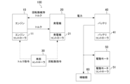
- FIG. 2 is a block diagram schematically showing a configuration example of a vehicle control device.
- FIG. 3 is a block diagram schematically showing a configuration example of a vehicle control device according to a comparative example.
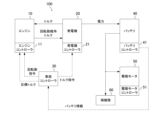
- FIG. 4 is a block diagram schematically showing a configuration example of a vehicle control device.
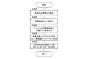
- FIG. 5 is a flowchart showing an example of control processing in the vehicle control device.
- FIG. 6 is a flowchart showing an example of control processing in the vehicle control device.
- FIG. 7 is a diagram showing a setting example in the case of setting the torque and rotation speed in the low power generation control state.
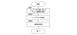
- FIG. 8 is a flowchart showing an example of control processing in the vehicle control device.
- FIG. 9 is a diagram showing a switching example when the engine speed is switched according to the vehicle speed in the low power generation control state.
- FIG. 10 is a diagram showing a switching example when the engine speed is switched according to the
- FIG. 1 is a diagram showing a schematic configuration diagram of a vehicle 1. As shown in FIG. The vehicle 1 is a series hybrid vehicle, and the power generation control system for the series hybrid vehicle will be mainly described in this embodiment.
- the vehicle 1 includes an engine 10 , a generator 20 , a battery 40 , a drive motor 50 , accessories 60 , gears 71 and drive wheels 72 .
- the engine 10 drives the generator 20 to generate power
- the electric power generated by the generator 20 drives the drive motor 50 .
- the engine 10 is an internal combustion engine, such as a gasoline engine.
- Engine 10 is connected to power generator 20 so as to be able to transmit power.
- the generator 20 is a motor generator, and performs motoring of the engine 10 in addition to power generation. Motoring is performed by driving the engine 10 in a stopped state with the generator 20 .
- the drive motor 50 is a motor generator and generates driving force for the vehicle 1 .
- the driving force generated by the driving motor 50 is transmitted to the driving wheels 72 through the gear 71, which is a reduction gear.
- the drive motor 50 also regenerates energy by being driven by the power from the drive wheels 72 .
- the energy regenerated as electric power by the drive motor 50 can be charged to the battery 40 .
- the battery 40 stores the power generated by the generator 20 and the power regenerated by the drive motor 50.
- a lithium ion secondary battery for example, can be used as the battery 40 .
- a discharge request SOC (State Of Charge) is set for the battery 40 .
- the SOC is a parameter that indicates the state of charge of the battery 40, and the discharge request SOC is set in advance as a value for defining the full charge of the battery 40.
- FIG. In other words, the full charge of the battery 40 is defined by the discharge request SOC, and the full charge is defined, for example, when the SOC as the charging rate is 90%.
- the drive wheels 72 and the engine 10 are independent, and the engine 10 is connected only to the generator 20. Also, the engine 10 and the generator 20 function as a power generation unit and constitute a power generation system.
- the auxiliaries 60 are devices installed in the vehicle 1 that require electric power.
- the accessories 60 are lights, speakers, car navigation systems, air conditioners, and the like.
- the vehicle 1 further includes an engine controller 11 , a generator controller 21 , a vehicle controller 30 , a battery controller 41 and a drive motor controller 51 .
- the engine controller 11, the generator controller 21, the vehicle controller 30, the battery controller 41, and the drive motor controller 51 are connected so as to be able to communicate with each other.
- the vehicle controller 30 is composed of one or more microcomputers having a central processing unit (CPU), read only memory (ROM), random access memory (RAM) and an input/output interface (I/O interface).
- the vehicle controller 30 can also be called a VCM (Vehicle Control Module).
- various controls are performed by executing programs stored in the ROM or RAM by the CPU. The same applies to the engine controller 11, the generator controller 21, the battery controller 41, and the drive motor controller 51.
- the generator controller 21 controls the generator 20.
- Generator controller 21 further includes a first inverter, which is the inverter for generator 20 .
- the first inverter may have a configuration different from that of the generator controller 21 .
- the generator controller 21 controls the generator 20 by controlling the first inverter.
- a drive motor controller 51 controls the drive motor 50 .
- Drive motor controller 51 further includes a second inverter, which is the inverter for drive motor 50 .
- the second inverter may have a configuration different from that of the drive motor controller 51 .
- the drive motor controller 51 controls the drive motor 50 by controlling the second inverter.
- the first inverter connects to the generator 20 and the battery 40 .
- the first inverter converts the AC current supplied from the generator 20 into a DC current and supplies the DC current to the battery 40 .
- the battery 40 is charged with the electric power generated by the generator 20 .
- the first inverter further converts the DC current supplied from the battery 40 into AC current and supplies the AC current to the generator 20 .
- the power of the battery 40 drives the generator 20 .
- Signals such as current, voltage, and SOC are also input to the generator controller 21 from the generator 20 , the drive motor 50 , and the battery 40 .
- the relationship between the second inverter, drive motor 50 and battery 40 is the same.
- the engine controller 11 controls the engine 10.
- the engine controller 11 controls a throttle valve, a fuel injection valve, an ignition plug, etc., and adjusts intake air amount, injection amount, ignition timing, etc., to execute engine control.
- the engine control signal can be further input to the vehicle controller 30 via the engine controller 11 .
- the vehicle controller 30 comprehensively controls the engine 10, generator 20, battery 40, drive motor 50, and the like.
- the vehicle controller 30 receives signals from an accelerator opening sensor 91 for detecting an accelerator opening APO and a shift position sensor 92 for detecting a shift position (range) selected by a driver's operation.
- FIG. 2 and 4 are block diagrams schematically showing configuration examples of the control device 100 of the vehicle 1.
- FIG. FIG. 3 is a block diagram schematically showing a configuration example of a vehicle control device according to a comparative example.
- a control device 100 of the vehicle 1 is a device for executing power generation control in the vehicle 1, and includes an engine 10, a generator 20, a battery 40, and the like. 2 to 4 show examples of relationships when power generation control and engine control are executed in a vehicle.
- Figure 2 shows an example of the relationship in the normal power generation control state
- Figure 3 shows an example of the relationship in the E-ISC (Engine-Idle Speed Control) state as a comparative example
- Figure 4 shows the relationship in the low power generation control state.
- the electric power generated by the generator 20 is supplied to the battery 40, the drive motor 50, or the accessories 60. Further, the total value of the electric power generated by the generator 20 and the electric power of the battery 40 is supplied to the drive motor 50 and the accessories 60 .
- the generator 20 maintains the rotation speed of the engine 10 by generating rotation speed maintenance torque.
- the rotation speed maintaining torque can also be considered as negative torque, friction torque, etc. when the shaft torque of the engine 10 is used as a reference.
- the generator controller 21 performs switching control of the first inverter so that the target rotation speed according to the rotation speed command output from the vehicle controller 30 is achieved. That is, the generator 20 loads the engine 10 with the rotation speed maintaining torque by switching control of the first inverter. For example, when the rotation speed of the generator 20 connected to the engine 10 is higher than the target rotation speed, rotation speed maintenance torque is applied to lower the rotation speed of the generator 20 to suppress the rotation of the engine 10 . On the other hand, when the rotation speed of the generator 20 connected to the engine 10 is lower than the target rotation speed, the rotation speed maintaining torque of the generator 20 is reduced.
- torque control is executed to increase or decrease the torque of the engine 10 so as to achieve the torque required for power generation, and the generator 20 generates power so as to achieve the rotation speed based on the torque required for power generation.
- Rotational speed control is performed to increase or decrease the rotational speed of the machine 20 . That is, the generator 20 generates the torque necessary for power generation and the torque necessary for maintaining the rotational speed, thereby generating power while maintaining the rotational speed of the engine 10 .
- a value obtained by multiplying the product of the torque generated by the generator 20 and the rotation speed of the generator 20 by a coefficient is the value of the power generated by the generator 20 .
- the engine 10 has a property of varying with respect to the torque command value, and often generates a large value of torque with respect to the torque command value. Also, it is known that the battery 40 has a property that the chargeable power PIN becomes smaller in a low temperature environment.
- FIG. 3 shows an example of implementing E-ISC as a comparative example of the present embodiment.
- E-ISC as a comparative example
- the vehicle controller 30 outputs an idling speed command to the engine controller 11 and stops switching control so that the generator controller 21 does not perform switching control. A command is output.
- the idling speed command By outputting the idling speed command to the engine controller 11 in this way, the engine 10 is controlled to the idling speed, so that the occurrence of racing can be suppressed.
- switching control of the first inverter of the generator 20 is not performed, there is no output from the battery 40 to the first inverter, and no electric power is generated from the generator 20 .
- the generator 20 in the E-ISC state, the generator 20 is in a no-load state while operating the engine 10 at the idling speed. Therefore, the battery 40 is in a state of only discharging, and the SOC of the battery 40 continues to decrease.
- the power generator 20 is set to low power when the engine 10 is caused to execute the rotation speed control. Carry out power generation. That is, in the present embodiment, when the chargeable power PIN is lowered as in a low-temperature environment, the SOC of the battery 40 does not fall below the necessary amount, for example, the SOC lower limit so that the vehicle 1 does not run out of electricity. A necessary amount of the SOC of the battery 40 is secured by performing low power generation. An example of this low power generation control is shown in FIG.
- the low power generation control state can also be referred to as a load ISC (Idle Speed Control) state because the engine 10 is controlled in rotation speed and the generator 20 is torque controlled to generate power.
- load ISC Idle Speed Control
- normal power generation control see FIG. 2
- low power power generation control see FIG. 4
- the minimum running of the vehicle 1 is controlled.
- Example of low power generation control As shown in FIG. 4, in the low-power generation control state, the vehicle controller 30 outputs a rotational speed command to the engine controller 11, and outputs the state of the battery 40, for example, the chargeable power PIN to the generator controller 21. Outputs the corresponding torque command. That is, in the low-power generation control state, it is possible to obtain generated power during rotation control by the engine 10 by issuing a torque command to the generator 20 . As a result, it is possible to suppress the speed of the engine 10 from running up and the risk of the battery 40 running out of electricity.
- the engine controller 11 executes rotation speed control based on the rotation speed of the engine 10 detected by a rotation speed detection sensor, for example, a crank angle sensor. That is, the engine controller 11 calculates the difference between the detection value of the rotation speed detection sensor and the target value according to the rotation speed command, and based on the difference value, the air amount, fuel injection, throttle valve opening, Rotation speed control is executed by adjusting ignition timing and the like. By executing this rotation speed control, the rotation speed maintaining torque is output from the engine 10 side.
- torque control is executed to increase or decrease the torque of the generator 20 so as to achieve the torque required for power generation, and the engine 10 is controlled so that the engine 10 reaches a predetermined reference low speed rotation speed. Execute speed control to increase or decrease the speed of the
- the vehicle controller 30 when the vehicle controller 30 outputs a torque command to the generator 20, it is preferable to notify the engine controller 11 of the same value as the torque command as the target torque. As a result, it becomes possible to correct the reference torque when the engine 10 feeds back the rotational speed when torque is applied to the engine 10 from the generator 20, based on the target torque.
- the vehicle controller 30 acquires battery information regarding the battery 40 from the battery controller 41 .
- This battery information includes a battery warm-up determination flag, short-term chargeable power PIN_S, long-term chargeable power PIN_L, and low temperature upper limit SOC.
- the battery warm-up determination flag is a flag indicating whether or not warm-up of the battery has been completed. Specifically, when the battery warm-up determination flag is on, it indicates that the battery has been warmed up, and when the battery warm-up determination flag is off, it indicates that the battery has been warmed up. indicates no Further, when the cell temperature of the battery 40 is equal to or higher than the temperature threshold, the battery controller 41 outputs ON as a battery warm-up determination flag to the vehicle controller 30, and when the cell temperature of the battery 40 is less than the temperature threshold, outputs OFF to the vehicle controller 30 as a battery warm-up determination flag.
- This temperature threshold value is a value that can determine the temperature at which the performance of the battery 40 can be exhibited, and can be appropriately set based on experimental data or the like. Note that the battery controller 41 may determine whether the cell temperature of the battery 40 is equal to or lower than the temperature threshold based on the voltage of the battery 40 or the like.
- the chargeable power PIN is information indicating the value of power that can be charged by the battery 40 .
- Short-term chargeable power PIN_S is power that can charge battery 40 for a short period of time.
- the short-term chargeable electric power PIN_S corresponds to electric power generated by an increase in the engine speed after engine 10 is started, or electric power capable of absorbing regenerative charging electric power while the vehicle is running (especially at high speed).
- the time for determining the short-term chargeable power PIN_S is in the range of several seconds to several tens of seconds or less. 40, and is at least shorter than the time range for determining the long-term chargeable power PIN_L, which will be described later.
- the battery controller 41 calculates the short-term chargeable power PIN_S based on the SOC of the battery 40 and the temperature of the battery 40 (battery temperature).
- the long-term chargeable power PIN_L is power that can charge the battery 40 for a long period of time.
- Long-term chargeable power PIN_L corresponds to chargeable power required to complete warm-up of battery 40 by charging.
- the time for determining the long-term chargeable power is a time within the range of several hundred seconds to several tens of minutes.
- Battery controller 41 calculates long-term chargeable power PIN_L based on the SOC of battery 40 and the temperature of battery 40 .
- the long-term chargeable power PIN_L means the power with which the battery 40 can be stably and continuously charged.
- the long-term chargeable power PIN_L functions as the low-temperature chargeable power PIN based on the continuously available long-term second value.
- the short-term chargeable power is also called instantaneous chargeable power, and the long-term chargeable power is also called continuously chargeable power.
- the chargeable power PIN may be obtained by measuring the voltage and temperature of the battery 40 .
- the chargeable power PIN may be obtained by measuring the voltage, current and temperature of the battery 40 .
- the chargeable power of battery 40 may be obtained based on short-term chargeable power PIN_S and long-term chargeable power PIN_L. For example, when the temperature is low, the chargeable power of the battery 40 decreases, but it is important to secure a certain amount of charge. Therefore, for example, the chargeable power of the battery 40 can be obtained by multiplying the difference between the long-term chargeable power PIN_L and the short-term chargeable power PIN_S by a predetermined ratio. As a result, it is possible to appropriately set the amount of charge that allows the battery 40 to be charged in a short period of time, based on the long-term chargeable power.
- the low temperature upper limit SOC is a value indicating the upper limit SOC when the temperature of the battery 40 becomes low. Since the upper limit value of the SOC of the battery 40 is determined according to the battery temperature, the upper limit SOC when the battery 40 reaches a predetermined low temperature is also set in advance. In addition, the upper limit SOC at which the short-term chargeable power PIN_S can be realized is also set in advance according to the battery temperature. Since the chargeable power PIN decreases even if the SOC rises, low power generation control can be executed using the low temperature upper limit SOC so that the chargeable power PIN does not decrease too much.
- FIG. 5 is a flowchart showing an example of control processing in the control device 100 of the vehicle 1.
- this control processing is executed by the vehicle controller 30 based on a program stored in a storage unit (not shown). Also, this control process is always executed in each control cycle.
- the vehicle controller 30 calculates the power required for the vehicle 1.
- This required power is the sum of the power required for the drive motor 50 and the power required for the accessories 60 .
- the electric power required for the drive motor 50 is calculated based on, for example, the depression amount of the accelerator pedal, the running state of the vehicle 1, and the like. Further, the electric power required for auxiliary equipment 60 is calculated based on the total value of electric power required for each device constituting auxiliary equipment 60 .
- the vehicle controller 30 calculates the required power generation torque based on the required electric power of the vehicle 1 and the SOC of the battery 40 calculated at step S401. For example, when the SOC of the battery 40 is lower than the reference value, the torque required for power generation is calculated to increase the power generation amount above the reference power generation amount. On the other hand, when the SOC of the battery 40 is higher than the reference value, the torque required for power generation is calculated to make the amount of power generation less than the reference amount.
- the required power generation torque is calculated so as to charge the battery 40 so as not to exceed the low temperature upper limit SOC. Therefore, it is possible to prevent the chargeable power PIN from decreasing due to the increase in the SOC of the battery 40 .
- step S403 the vehicle controller 30 obtains the target rotational speed and target torque of the engine 10 based on the power generation required torque calculated in step S402.
- a fixed value can be set as the target rotation speed in the low power generation control state, and this fixed value can be appropriately set based on experimental data or the like. For example, when the rotation speed range of the engine 10 in the normal power generation control state is approximately 1400 rpm to 6000 rpm, the target rotation speed can be set to a value of approximately 1400 rpm to 2200 rpm. Also, the target torque is set to the same value as the torque required for power generation calculated in step S402.
- step S404 the vehicle controller 30 outputs the power generation required torque calculated in step S402 to the generator controller 21 as a torque command.
- the vehicle controller 30 outputs to the engine controller 11 the target rotational speed and the target torque obtained at step S403.
- FIG. 6 is a flowchart showing an example of control processing in the control device 100 of the vehicle 1. As shown in FIG. Also, this control processing is executed by the vehicle controller 30 based on a program stored in a storage unit (not shown). Also, this control process is always executed in each control cycle. Also, this control process will be described with reference to FIGS. 1 to 5 as appropriate.
- step S501 the vehicle controller 30 acquires the battery warm-up determination flag, the short-term chargeable power PIN_S, the long-term chargeable power PIN_L, and the low temperature upper limit SOC from the battery controller 41 as battery information.
- the vehicle controller 30 determines whether the warm-up determination flag acquired at step S501 is ON. Note that the warm-up determination flag is turned on when the warm-up of the battery 40 is completed, and the warm-up determination flag is turned off when the warm-up of the battery 40 is not completed. That is, it is determined whether the warm-up of the battery 40 has been completed. If the warm-up determination flag is ON, the process proceeds to step S505. On the other hand, if the warm-up determination flag is off, the process proceeds to step S503. In this manner, vehicle controller 30 determines whether or not warm-up of battery 40 is completed based on the battery warm-up determination flag indicating the state of battery 40 . Then, vehicle controller 30 estimates that the temperature of battery 40 is equal to or lower than a predetermined temperature when warm-up of battery 40 is not completed.
- step S503 the vehicle controller 30 determines whether or not the vehicle required power is equal to or greater than the threshold TH1.
- the threshold value TH1 is a reference value for determining whether or not the electric power required to perform normal power generation control is required, and can be appropriately set based on experimental data or the like. If the vehicle required electric power is equal to or greater than the threshold TH1, the process proceeds to step S505. On the other hand, when the vehicle required electric power is less than the threshold TH1, the process proceeds to step S504.
- the normal power generation control state is set.
- the transition to the low power generation control state is permitted only when the warm-up of the battery 40 is not completed and the temperature of the battery 40 is assumed to be low.
- the normal power generation control state is set.
- step S504 the vehicle controller 30 determines whether or not the short-term chargeable power PIN_S obtained in step S501 is equal to or greater than the threshold TH2.
- the threshold TH2 is a reference value for determining whether or not to turn on the slow lamp when performing the low power generation control, and can be appropriately set based on experimental data or the like. If the short-term chargeable power PIN_S is equal to or greater than the threshold TH2, the process proceeds to step S506. On the other hand, when the short-term chargeable power PIN_S is less than the threshold TH2, the process proceeds to step S507.
- the slow lamp is a vehicle driving performance deterioration notification for notifying the driver that the driving performance of the vehicle 1 is deteriorating.
- the running performance is degraded in the low power generation control state.
- the short-term chargeable power PIN_S is less than the threshold TH2
- the value of the torque command for the generator 20 becomes low, so the amount of power generated by the generator 20 decreases, and the running performance of the vehicle 1 tends to deteriorate. becomes. Therefore, in such a state, the slow lamp is turned on to notify the occupants of the vehicle 1 that the running performance is degraded.
- step S505 the vehicle controller 30 sets the power generation state of the engine 10 and the power generator 20 to the normal power generation control state. In this case, the vehicle controller 30 executes normal power generation control shown in FIG.
- step S506 the vehicle controller 30 sets the power generation state of the engine 10 and the generator 20 to the low power generation control state. In this case, the vehicle controller 30 executes the low power generation control shown in FIG.
- step S507 the vehicle controller 30 sets the power generation state of the engine 10 and the generator 20 to the low power generation control state, and lights the slow lamp.
- the slow lamp is not turned on and the low power generation control state is set.
- the short-term chargeable power PIN_S of the battery 40 is less than the threshold TH2, the slow lamp is turned on to enter the low power generation control state.
- the power demand of the vehicle 1 and the state of the battery 40 are used to control the low power generation control. It is possible to appropriately determine the necessity of the state. By minimizing the time zone in which the low power generation control state is set in this way, it is possible to reduce the frequency of occurrence of a state in which the running performance of the vehicle 1 is degraded. Also, in a scene in which it is difficult for the occupant of the vehicle 1 to feel the revving up of the engine 10, for example, during acceleration, the normal power generation control state is positively set. In this way, in a scene where it is difficult to feel the engine 10 revving up, driving performance can be improved by positively setting the normal power generation control state.
- the low power generation control in order to prevent the vehicle 1 from running out of electricity, in the low power generation control, power is generated for the amount necessary for the SOC of the battery 40, for example, so as not to fall below the SOC lower limit value.
- the low power generation control may be performed so as to increase the required SOC of the battery 40 by several percent.
- Modification 1 An example of setting the low power generation control and the normal power generation control based on the state of the battery, that is, the temperature of the battery and the electric power demanded by the vehicle 1 has been described above. An example in which delay processing and restriction processing are executed in consideration of the response delay of the engine 10 and the like in the low power generation control state will be described below as Modified Example 1.
- FIG. 1 An example in which delay processing and restriction processing are executed in consideration of the response delay of the engine 10 and the like in the low power generation control state will be described below as Modified Example 1.
- FIG. 7 is a diagram showing a setting example in the case of setting the torque and rotation speed in the low power generation control state.
- the upper side of FIG. 7 shows a setting example of the torque of the generator 20
- the lower side of FIG. 7 shows a transition example of the rotational speed of the engine 10 .
- the vertical axis of FIG. 7 indicates the time axis.
- the vertical axis shown on the upper side of FIG. 7 indicates the torque value of the generator 20, and the vertical axis shown on the lower side of FIG.
- a dotted straight line L2 indicating the target torque of the generator 20 and an upper limit value T2 of the target torque are shown as a comparative example.
- the transition of the actual shaft torque of the engine 10 in response to the target torque becomes a curve close to the curve C1.
- a dashed curve C12 representing the transition of the rotation speed of the engine 10 corresponding to the transition of the actual shaft torque of the engine 10 in response to the target torque as a comparative example is shown.
- a straight line L1 indicating the target torque of the generator 20 set in the low power generation control state
- a curve C1 representing the transition of the actual shaft torque of the engine 10 in response to the target torque (straight line L1) is shown.
- the lower side of FIG. 7 shows a curve C11 representing the transition of the rotation speed of the engine 10 corresponding to the curve C1.
- the rate limit RL1 is set for the torque commanded to the generator 20 . Also, a delay period D1 for delaying the application of torque from the start timing of the engine 10 and an upper limit value T1 for limiting the upper limit of the torque command are set.
- a limit function is provided. Note that although Modification 1 shows an example in which a rate limit function, a delay timer function, and a limit function are provided, at least one of these functions may be provided.
- the delay period D1 can be set based on the water temperature of the engine 10. For example, a longer period can be set as the water temperature of the engine 10 decreases.
- the rate limit RL1 can be a constant value. Note that the rate limit RL1 is a value capable of alleviating rapid fluctuations in the torque of the engine 10, and can be appropriately set based on experimental data or the like.
- the upper limit value T1 can be the maximum torque value that the engine 10 can exhibit in the low power generation control state.
- FIG. 8 is a flowchart showing an example of control processing in the control device 100 of the vehicle 1.
- this control processing is executed by the vehicle controller 30 based on a program stored in a storage unit (not shown). Also, this control process is always executed in each control cycle.
- step S601 the vehicle controller 30 determines whether or not the water temperature of the engine 10 is equal to or lower than the water temperature threshold. set.
- the delay period D1 is set, and the torque load to the engine 10 is waited for a predetermined time.
- the value obtained by the temperature sensor of the engine 10 can be obtained from the engine controller 11 .
- step S602 the vehicle controller 30 determines whether or not to increase or decrease the torque of the generator 20. If the torque of the generator 20 is increased or decreased, the rate limit RL1 is set during the period during which the torque is increased or decreased. do.
- step S603 the vehicle controller 30 sets the maximum torque value that the engine 10 can exhibit in the low power generation control state as the upper limit value T1.
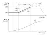
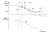
- Modification 2 shows an example in which the rotation speed of the engine 10 is switched according to the state of the vehicle 1, that is, the vehicle speed, in the low power generation control state. Specifically, Modification 2 shows an example of switching between two types of values (LU1 and UR1 shown in FIGS. 9 and 10) as the target rotation speed of the engine 10 .
- FIGS. 9 and 10 are diagrams showing examples of switching when the rotation speed of the engine 10 is switched according to the vehicle speed of the vehicle 1 in the low power generation control state.
- FIG. 9 shows an example of switching the rotation speed of the engine 10 when the vehicle speed V1 of the vehicle 1 increases
- FIG. 10 shows an example of switching the rotation speed of the engine 10 when the vehicle speed V2 of the vehicle 1 decreases. show.
- the horizontal axis shown in FIGS. 9 and 10 indicates the time axis.
- 9 and 10 indicate the rotational speed of the engine 10
- the vertical axis indicated on the lower side of FIGS. 9 and 10 indicate the vehicle speed.
- FIGS. 9 and 10 show an example in which two types of rotation speeds UR1 and LR1 are set according to the state of the vehicle 1, that is, the vehicle speed.
- the rotation speed UR1 is an example of the rotation speed on the high rotation side
- the rotation speed LR1 is an example of the rotation speed on the low rotation side.
- the engine sound emitted by the engine 10 is a sound that does not make the user of the vehicle 1 feel uncomfortable. Therefore, when the vehicle 1 is stopped or when the vehicle 1 is at a low speed, that is, when the vehicle speed is less than the threshold TH3, the rotation speed LR1 is set.
- the rotational speed UR1 is set.
- the rotational speed LR1 is set, less electric power is obtained than when the rotational speed UR1 is set. Therefore, it is preferable to set the two types of rotation speeds UR1 and LR1 in consideration of the discomfort assumed to be given to the user of the vehicle 1 and the electric power required for the vehicle.
- the threshold TH3 is a reference value for switching between the two types of rotation speeds UR1 and LR1, and can be appropriately set based on experimental data or the like, taking into consideration the sense of discomfort given to the user of the vehicle 1, the required electric power of the vehicle 1, and the like. be.
- two types of rotation speed are switched according to the required electric power and vehicle speed.
- the values of the two rotation speeds UR1 and LR1 are set to values within the range of about 1400 rpm to 2200 rpm. can do.
- the value of the rotation speed LR1 can be set to a low value within the range of 1400 rpm to 2200 rpm
- the value of the rotation speed UR1 can be set to a high value within the range of 1400 rpm to 2200 rpm.
- the straight lines L21 and L31 are the target rotation speed of the engine 10, and the curves C21 and C31 are the actual rotation speed of the engine 10.
- the straight lines L22 and L32 are the target rotation speed of the engine 10 as a comparative example, and the curves C22 and C32 are the actual rotation speed of the engine 10 as a comparative example.
- an increase in vehicle speed or an increase in required electric power of the vehicle 1 occurs when the driver of the vehicle 1 intends to travel or accelerate. In such a case, the occupants of the vehicle 1 do not feel uncomfortable even if the number of revolutions is increased and the background noise becomes louder. Therefore, the rotation speed can be switched according to the vehicle speed and the required electric power of the vehicle 1 . In this way, by increasing the rotation speed of the engine 10 according to the travel request of the driver of the vehicle 1, it is possible to increase the electric power obtained in the low power generation control state, and to satisfy the higher travel performance request. can.
- the two rotation speeds UR1 and LR1 may be switched based on conditions other than the vehicle speed. For example, if it is determined in step S504 (see FIG. 6) that short-term chargeable power PIN_S is equal to or greater than threshold TH2, rotation speed UR1 can be set in step S506. On the other hand, when it is determined that short-term chargeable power PIN_S is less than threshold TH2, rotation speed LR1 can be set in step S507. Further, when the rotational speed LR1 is set, the slow lamp may be lit or blinked. Further, in the modification 2, an example is shown in which two types of rotation speeds UR1 and LR1 are set and switched between them. is applicable.
- the control device 100 of the vehicle 1 includes the generator 20, the engine 10 connected to the generator 20, the drive motor 50 that drives the vehicle 1, the generator 20 and
- a vehicle control method includes a battery 40 electrically connected to a drive motor 50 , and power generated by a generator 20 is supplied to at least one of the battery 40 and the drive motor 50 .
- the power generation required torque is determined based on the required electric power of the vehicle 1 and the state of the battery 40.
- the low power generation control is executed to cause the power generator 20 to generate power.
- torque control is executed to increase or decrease the torque of the generator 20 so as to achieve the torque required for power generation calculated based on the required power of the vehicle 1 and the state of the battery 40, and the engine 10 is a predetermined reference low-speed rotation speed.
- the low power generation control can be executed. Charging can be continued and the risk of running out of electricity can be reduced.
- the control method of the vehicle 1 it is determined whether the warm-up of the battery 40 is completed based on the state of the battery 40, and if the warm-up of the battery 40 is not completed, It is estimated that the temperature of the battery 40 is below the predetermined temperature. Then, in steps S501 to S504, S506, and S507, when the warm-up of the battery 40 is not completed and the required power of the vehicle 1 is less than the threshold TH1 (an example of the first threshold), the low power Execute power generation control.
- the threshold TH1 an example of the first threshold
- the low electric power generation control is executed. proper charging can be performed.
- the power generation required torque (an example of the drive torque target value) is calculated based on the required electric power of the vehicle 1 and the state of the battery 40, and the engine 10 is calculated based on the power generation required torque.
- the generator 20 controls the rotation speed of the generator 20 based on the rotation speed based on the torque required for power generation, thereby executing normal power generation control in which the generator 20 generates electric power.
- torque control is executed to increase or decrease the torque of the engine 10 so as to achieve the torque required for power generation calculated based on the required electric power of the vehicle 1 and the state of the battery 40
- Rotational speed control is executed to increase or decrease the rotational speed of the generator 20 so as to achieve the rotational speed based on the power generation required torque.
- step S506 and S507 in the low power generation control, the power generated by the generator 20 and the chargeable power PIN of the battery 40 according to the temperature of the battery 40 Based on this, torque control of the generator 20 and rotation speed control of the engine 10 are executed.
- the torque control of the generator 20 and the rotation speed of the engine 10 are performed so that the power generated by the generator 20 is within the range of the chargeable power PIN of the battery 40 according to the temperature of the battery 40. control and execute.
- low power generation control is executed so that the power generated by the generator 20 is within the range of the chargeable power PIN of the battery 40. Therefore, appropriate power generation according to the chargeable power PIN of the battery 40 is performed. control can be realized. As a result, it is possible to prevent the SOC of the battery 40 from depleting, and to continue charging even when the vehicle 1 is stopped when the power consumption of the vehicle 1 is low. In addition, the temperature of the battery 40 can be increased, and the low chargeable power state due to the low temperature can be quickly exited.
- steps S506 and S507 in the low power generation control, based on the power generated by the generator 20 and the upper limit SOC of the battery 40 determined according to the battery temperature, Torque control of the generator 20 and rotation speed control of the engine 10 are executed.
- torque control of the generator 20 and rotation speed control of the engine 10 are executed so that the power generated by the generator 20 does not exceed the upper limit SOC of the battery 40 determined according to the battery temperature. .
- low power generation control is executed so that the power generated by the generator 20 does not exceed the upper limit SOC of the battery 40, so appropriate power generation control according to the upper limit SOC of the battery 40 can be realized. can. Also, it is possible to prevent the chargeable power PIN from decreasing due to the increase in the SOC of the battery 40 .
- the delay processing for delaying the torque control start timing of the generator 20 and the maximum At least one of a torque limiting process for limiting the driving torque and a limiting process for limiting a change rate when changing the driving torque of the generator 20 is executed.
- at least one of delay processing for setting a delay period D1, torque restriction processing for setting an upper limit value T1, and restriction processing for setting a rate limit RL1 can be executed. can.
- Low speed rotation speed UR1 is set.
- steps S506 and S507 in the low power generation control, based on at least one of the required electric power of the vehicle 1 and the vehicle speed of the vehicle 1, the rotation speed of the engine 10 is set to the first low rotation speed LR1 and the second low rotation speed LR1. Switch the number of revolutions UR1.
- the short-term chargeable power PIN_S (an example of chargeable power) of the battery 40 corresponding to the temperature of the battery 40 is set as a threshold value in the low power generation control. If it is less than TH2 (an example of the second threshold), a vehicle driving performance deterioration notification process is executed to notify the occupant that the driving performance of the vehicle 1 will deteriorate.
- a slow lamp can be turned on or blinked.
- control device 100 of the vehicle 1 includes a generator 20, an engine 10 connected to the generator 20, a drive motor 50 for driving the vehicle 1, and electrically connected to the generator 20 and the drive motor 50. and a battery 40, and electric power generated by the generator 20 is supplied to at least one of the battery 40 and the drive motor 50.
- the control device 100 calculates the power generation required torque (an example of the drive torque target value) based on the required electric power of the vehicle 1 and the state of the battery 40, and calculates the power generation required torque.
- a predetermined reference low speed rotation speed for example, rotation speed UR1 and LR1
- a vehicle controller 30 an example of a controller that executes
- the low power generation control can be executed. Charging can be continued and the risk of running out of electricity can be reduced.
- Each processing procedure shown in this embodiment is an example for realizing this embodiment. Often, part of each processing procedure may be omitted or other processing procedures may be added.
- each process shown in this embodiment is executed based on a program for causing a computer to execute each processing procedure. Therefore, the present embodiment can also be understood as an embodiment of a program that realizes the function of executing each process and a recording medium that stores the program. For example, an update process for adding new functionality to the controller may cause the program to be stored in the memory of the controller. As a result, it is possible to cause the updated control device to perform each process shown in this embodiment.
Landscapes
- Engineering & Computer Science (AREA)
- Chemical & Material Sciences (AREA)
- Combustion & Propulsion (AREA)
- Transportation (AREA)
- Mechanical Engineering (AREA)
- Automation & Control Theory (AREA)
- Life Sciences & Earth Sciences (AREA)
- Sustainable Development (AREA)
- Sustainable Energy (AREA)
- Power Engineering (AREA)
- Electric Propulsion And Braking For Vehicles (AREA)
- Control Of Eletrric Generators (AREA)
Priority Applications (6)
| Application Number | Priority Date | Filing Date | Title |
|---|---|---|---|
| EP21964977.9A EP4438426B1 (en) | 2021-11-26 | 2021-11-26 | Control method for vehicle and control device for vehicle |
| MX2024005965A MX2024005965A (es) | 2021-11-26 | 2021-11-26 | Metodo de control para vehiculo y dispositivo de control para vehiculo. |
| CN202180104265.4A CN118251337B (zh) | 2021-11-26 | 2021-11-26 | 车辆的控制方法以及车辆的控制装置 |
| JP2023563442A JP7647924B2 (ja) | 2021-11-26 | 2021-11-26 | 車両の制御方法及び車両の制御装置 |
| US18/712,930 US12344254B2 (en) | 2021-11-26 | 2021-11-26 | Control method for vehicle and control device for vehicle |
| PCT/JP2021/043374 WO2023095281A1 (ja) | 2021-11-26 | 2021-11-26 | 車両の制御方法及び車両の制御装置 |
Applications Claiming Priority (1)
| Application Number | Priority Date | Filing Date | Title |
|---|---|---|---|
| PCT/JP2021/043374 WO2023095281A1 (ja) | 2021-11-26 | 2021-11-26 | 車両の制御方法及び車両の制御装置 |
Publications (1)
| Publication Number | Publication Date |
|---|---|
| WO2023095281A1 true WO2023095281A1 (ja) | 2023-06-01 |
Family
ID=86539180
Family Applications (1)
| Application Number | Title | Priority Date | Filing Date |
|---|---|---|---|
| PCT/JP2021/043374 Ceased WO2023095281A1 (ja) | 2021-11-26 | 2021-11-26 | 車両の制御方法及び車両の制御装置 |
Country Status (6)
| Country | Link |
|---|---|
| US (1) | US12344254B2 (cg-RX-API-DMAC7.html) |
| EP (1) | EP4438426B1 (cg-RX-API-DMAC7.html) |
| JP (1) | JP7647924B2 (cg-RX-API-DMAC7.html) |
| CN (1) | CN118251337B (cg-RX-API-DMAC7.html) |
| MX (1) | MX2024005965A (cg-RX-API-DMAC7.html) |
| WO (1) | WO2023095281A1 (cg-RX-API-DMAC7.html) |
Families Citing this family (2)
| Publication number | Priority date | Publication date | Assignee | Title |
|---|---|---|---|---|
| JP7375988B1 (ja) * | 2022-03-04 | 2023-11-08 | 三菱自動車工業株式会社 | 電動車両の制御装置 |
| CN120963661A (zh) * | 2025-09-23 | 2025-11-18 | 安徽江淮汽车集团股份有限公司 | 一种混动车型在低温环境下发动机串联发电的控制方法 |
Citations (6)
| Publication number | Priority date | Publication date | Assignee | Title |
|---|---|---|---|---|
| JPH1014296A (ja) * | 1996-06-25 | 1998-01-16 | Nissan Motor Co Ltd | ハイブリッド車の発電制御装置 |
| JPH11117840A (ja) * | 1997-10-09 | 1999-04-27 | Toyota Motor Corp | 内燃機関の始動装置および始動方法 |
| JP2004300957A (ja) | 2003-03-28 | 2004-10-28 | Mitsubishi Motors Corp | エンジンのアイドル制御装置 |
| JP2010173390A (ja) * | 2009-01-28 | 2010-08-12 | Nissan Motor Co Ltd | 車両の制御装置 |
| JP2012091562A (ja) * | 2010-10-25 | 2012-05-17 | Nissan Motor Co Ltd | ハイブリッド車両の制御装置 |
| JP2015074342A (ja) * | 2013-10-09 | 2015-04-20 | マツダ株式会社 | ハイブリッド車の制御装置 |
Family Cites Families (10)
| Publication number | Priority date | Publication date | Assignee | Title |
|---|---|---|---|---|
| JP3539406B2 (ja) * | 2001-06-25 | 2004-07-07 | 日産自動車株式会社 | ハイブリッド車両の制御装置 |
| JP2003018705A (ja) | 2001-06-27 | 2003-01-17 | Hitachi Unisia Automotive Ltd | ハイブリッド車両の発電制御装置 |
| JP4228085B2 (ja) * | 2007-02-07 | 2009-02-25 | トヨタ自動車株式会社 | 車両およびその制御方法、動力出力装置およびその制御方法、ならびに駆動装置およびその制御方法 |
| US9120480B2 (en) * | 2010-11-30 | 2015-09-01 | Daimler Ag | Battery warm-up apparatus of hybrid electric vehicle |
| US8409052B2 (en) * | 2011-04-29 | 2013-04-02 | Delta Electronics, Inc. | Starting method for hybrid electric vehicle and system architecture of hybrid electric vehicle |
| JP5312557B2 (ja) * | 2011-11-10 | 2013-10-09 | 三菱電機株式会社 | 電源管理装置、電源管理方法、および、電源管理システム |
| JP6745408B2 (ja) * | 2017-06-30 | 2020-08-26 | 本田技研工業株式会社 | 車両の制御装置 |
| RU2739098C1 (ru) * | 2017-12-15 | 2020-12-21 | Ниссан Мотор Ко., Лтд. | Способ управления прогревом катализатора для гибридного транспортного средства и устройство управления прогревом катализатора для гибридного транспортного средства |
| JP7132904B2 (ja) * | 2019-12-19 | 2022-09-07 | 本田技研工業株式会社 | プログラム更新方法 |
| JP2021154853A (ja) * | 2020-03-26 | 2021-10-07 | 本田技研工業株式会社 | ハイブリッド車両の制御装置 |
-
2021
- 2021-11-26 JP JP2023563442A patent/JP7647924B2/ja active Active
- 2021-11-26 EP EP21964977.9A patent/EP4438426B1/en active Active
- 2021-11-26 US US18/712,930 patent/US12344254B2/en active Active
- 2021-11-26 MX MX2024005965A patent/MX2024005965A/es unknown
- 2021-11-26 WO PCT/JP2021/043374 patent/WO2023095281A1/ja not_active Ceased
- 2021-11-26 CN CN202180104265.4A patent/CN118251337B/zh active Active
Patent Citations (6)
| Publication number | Priority date | Publication date | Assignee | Title |
|---|---|---|---|---|
| JPH1014296A (ja) * | 1996-06-25 | 1998-01-16 | Nissan Motor Co Ltd | ハイブリッド車の発電制御装置 |
| JPH11117840A (ja) * | 1997-10-09 | 1999-04-27 | Toyota Motor Corp | 内燃機関の始動装置および始動方法 |
| JP2004300957A (ja) | 2003-03-28 | 2004-10-28 | Mitsubishi Motors Corp | エンジンのアイドル制御装置 |
| JP2010173390A (ja) * | 2009-01-28 | 2010-08-12 | Nissan Motor Co Ltd | 車両の制御装置 |
| JP2012091562A (ja) * | 2010-10-25 | 2012-05-17 | Nissan Motor Co Ltd | ハイブリッド車両の制御装置 |
| JP2015074342A (ja) * | 2013-10-09 | 2015-04-20 | マツダ株式会社 | ハイブリッド車の制御装置 |
Non-Patent Citations (1)
| Title |
|---|
| See also references of EP4438426A4 |
Also Published As
| Publication number | Publication date |
|---|---|
| EP4438426A4 (en) | 2025-02-12 |
| JPWO2023095281A1 (cg-RX-API-DMAC7.html) | 2023-06-01 |
| JP7647924B2 (ja) | 2025-03-18 |
| CN118251337B (zh) | 2025-02-25 |
| CN118251337A (zh) | 2024-06-25 |
| US12344254B2 (en) | 2025-07-01 |
| MX2024005965A (es) | 2024-06-03 |
| US20240416918A1 (en) | 2024-12-19 |
| EP4438426B1 (en) | 2025-09-17 |
| EP4438426A1 (en) | 2024-10-02 |
Similar Documents
| Publication | Publication Date | Title |
|---|---|---|
| JP2790779B2 (ja) | ハイブリッド車両の発電制御装置 | |
| US20080119975A1 (en) | Hybrid Electric Vehicle Powertrain with Engine Start and Transmission Shift Arbitration | |
| JPWO2019116586A1 (ja) | ハイブリッド車両の制御方法、及び、制御装置 | |
| JPS6227603B2 (cg-RX-API-DMAC7.html) | ||
| CN111976700B (zh) | 一种车辆起步控制方法、装置、存储介质及系统 | |
| EP2993100A2 (en) | Regeneration controller for hybrid vehicle with two motors | |
| KR20130063271A (ko) | 하이브리드 차량의 엔진 제어 방법 | |
| JPWO2013077233A1 (ja) | 電動車両 | |
| JP7647924B2 (ja) | 車両の制御方法及び車両の制御装置 | |
| CN113924238A (zh) | 电动装置控制方法以及电动装置 | |
| CN117048584A (zh) | 扭矩控制方法、装置、电子设备及存储介质 | |
| JP2004242450A (ja) | ハイブリッド車両の制御装置 | |
| KR102873158B1 (ko) | 하이브리드 자동차 및 그를 위한 동력 제어 방법 | |
| US10954876B2 (en) | Vehicle system | |
| KR20170044526A (ko) | 하이브리드 차량 및 그 제어 방법 | |
| JP2006275019A (ja) | ハイブリッド車の制御装置 | |
| JP2012086645A (ja) | ハイブリッド車両の制御装置及び制御方法 | |
| JP6636840B2 (ja) | ハイブリッド車両の制御装置及びハイブリッド車両システム | |
| WO2023037419A1 (ja) | 車両の制御方法及び車両 | |
| CN118973878B (zh) | 车辆的控制方法及车辆 | |
| WO2025082084A1 (zh) | 动力系统的驱动控制方法、装置、存储介质及车辆 | |
| JP2004343926A (ja) | 車両の駆動力制御装置 | |
| JP2020117101A (ja) | ハイブリッド車両の制御装置 | |
| JP2020117102A (ja) | ハイブリッド車両の制御装置 | |
| KR102546717B1 (ko) | 마일드 하이브리드 차량의 연료분사 제어 방법 |
Legal Events
| Date | Code | Title | Description |
|---|---|---|---|
| 121 | Ep: the epo has been informed by wipo that ep was designated in this application |
Ref document number: 21964977 Country of ref document: EP Kind code of ref document: A1 |
|
| ENP | Entry into the national phase |
Ref document number: 2023563442 Country of ref document: JP Kind code of ref document: A |
|
| WWE | Wipo information: entry into national phase |
Ref document number: 202180104265.4 Country of ref document: CN |
|
| WWE | Wipo information: entry into national phase |
Ref document number: 2401003168 Country of ref document: TH |
|
| WWE | Wipo information: entry into national phase |
Ref document number: 18712930 Country of ref document: US |
|
| REG | Reference to national code |
Ref country code: BR Ref legal event code: B01A Ref document number: 112024010069 Country of ref document: BR |
|
| WWE | Wipo information: entry into national phase |
Ref document number: 2021964977 Country of ref document: EP |
|
| NENP | Non-entry into the national phase |
Ref country code: DE |
|
| ENP | Entry into the national phase |
Ref document number: 2021964977 Country of ref document: EP Effective date: 20240626 |
|
| ENP | Entry into the national phase |
Ref document number: 112024010069 Country of ref document: BR Kind code of ref document: A2 Effective date: 20240521 |
|
| WWG | Wipo information: grant in national office |
Ref document number: 202180104265.4 Country of ref document: CN |
|
| WWG | Wipo information: grant in national office |
Ref document number: 18712930 Country of ref document: US |
|
| WWG | Wipo information: grant in national office |
Ref document number: 2021964977 Country of ref document: EP |