WO2023090358A1 - 表面保護フィルム付き光学シート、及び、表面保護フィルム - Google Patents
表面保護フィルム付き光学シート、及び、表面保護フィルム Download PDFInfo
- Publication number
- WO2023090358A1 WO2023090358A1 PCT/JP2022/042546 JP2022042546W WO2023090358A1 WO 2023090358 A1 WO2023090358 A1 WO 2023090358A1 JP 2022042546 W JP2022042546 W JP 2022042546W WO 2023090358 A1 WO2023090358 A1 WO 2023090358A1
- Authority
- WO
- WIPO (PCT)
- Prior art keywords
- protective film
- optical sheet
- surface protective
- surface protection
- protection film
- Prior art date
- Legal status (The legal status is an assumption and is not a legal conclusion. Google has not performed a legal analysis and makes no representation as to the accuracy of the status listed.)
- Ceased
Links
Images

Classifications
-
- C—CHEMISTRY; METALLURGY
- C09—DYES; PAINTS; POLISHES; NATURAL RESINS; ADHESIVES; COMPOSITIONS NOT OTHERWISE PROVIDED FOR; APPLICATIONS OF MATERIALS NOT OTHERWISE PROVIDED FOR
- C09J—ADHESIVES; NON-MECHANICAL ASPECTS OF ADHESIVE PROCESSES IN GENERAL; ADHESIVE PROCESSES NOT PROVIDED FOR ELSEWHERE; USE OF MATERIALS AS ADHESIVES
- C09J7/00—Adhesives in the form of films or foils
- C09J7/20—Adhesives in the form of films or foils characterised by their carriers
- C09J7/22—Plastics; Metallised plastics
- C09J7/24—Plastics; Metallised plastics based on macromolecular compounds obtained by reactions involving only carbon-to-carbon unsaturated bonds
- C09J7/241—Polyolefin, e.g.rubber
- C09J7/243—Ethylene or propylene polymers
-
- B—PERFORMING OPERATIONS; TRANSPORTING
- B32—LAYERED PRODUCTS
- B32B—LAYERED PRODUCTS, i.e. PRODUCTS BUILT-UP OF STRATA OF FLAT OR NON-FLAT, e.g. CELLULAR OR HONEYCOMB, FORM
- B32B27/00—Layered products comprising a layer of synthetic resin
-
- B—PERFORMING OPERATIONS; TRANSPORTING
- B32—LAYERED PRODUCTS
- B32B—LAYERED PRODUCTS, i.e. PRODUCTS BUILT-UP OF STRATA OF FLAT OR NON-FLAT, e.g. CELLULAR OR HONEYCOMB, FORM
- B32B27/00—Layered products comprising a layer of synthetic resin
- B32B27/32—Layered products comprising a layer of synthetic resin comprising polyolefins
-
- B—PERFORMING OPERATIONS; TRANSPORTING
- B32—LAYERED PRODUCTS
- B32B—LAYERED PRODUCTS, i.e. PRODUCTS BUILT-UP OF STRATA OF FLAT OR NON-FLAT, e.g. CELLULAR OR HONEYCOMB, FORM
- B32B27/00—Layered products comprising a layer of synthetic resin
- B32B27/36—Layered products comprising a layer of synthetic resin comprising polyesters
-
- B—PERFORMING OPERATIONS; TRANSPORTING
- B32—LAYERED PRODUCTS
- B32B—LAYERED PRODUCTS, i.e. PRODUCTS BUILT-UP OF STRATA OF FLAT OR NON-FLAT, e.g. CELLULAR OR HONEYCOMB, FORM
- B32B7/00—Layered products characterised by the relation between layers; Layered products characterised by the relative orientation of features between layers, or by the relative values of a measurable parameter between layers, i.e. products comprising layers having different physical, chemical or physicochemical properties; Layered products characterised by the interconnection of layers
- B32B7/02—Physical, chemical or physicochemical properties
- B32B7/022—Mechanical properties
-
- B—PERFORMING OPERATIONS; TRANSPORTING
- B32—LAYERED PRODUCTS
- B32B—LAYERED PRODUCTS, i.e. PRODUCTS BUILT-UP OF STRATA OF FLAT OR NON-FLAT, e.g. CELLULAR OR HONEYCOMB, FORM
- B32B7/00—Layered products characterised by the relation between layers; Layered products characterised by the relative orientation of features between layers, or by the relative values of a measurable parameter between layers, i.e. products comprising layers having different physical, chemical or physicochemical properties; Layered products characterised by the interconnection of layers
- B32B7/04—Interconnection of layers
- B32B7/12—Interconnection of layers using interposed adhesives or interposed materials with bonding properties
-
- C—CHEMISTRY; METALLURGY
- C09—DYES; PAINTS; POLISHES; NATURAL RESINS; ADHESIVES; COMPOSITIONS NOT OTHERWISE PROVIDED FOR; APPLICATIONS OF MATERIALS NOT OTHERWISE PROVIDED FOR
- C09J—ADHESIVES; NON-MECHANICAL ASPECTS OF ADHESIVE PROCESSES IN GENERAL; ADHESIVE PROCESSES NOT PROVIDED FOR ELSEWHERE; USE OF MATERIALS AS ADHESIVES
- C09J201/00—Adhesives based on unspecified macromolecular compounds
-
- C—CHEMISTRY; METALLURGY
- C09—DYES; PAINTS; POLISHES; NATURAL RESINS; ADHESIVES; COMPOSITIONS NOT OTHERWISE PROVIDED FOR; APPLICATIONS OF MATERIALS NOT OTHERWISE PROVIDED FOR
- C09J—ADHESIVES; NON-MECHANICAL ASPECTS OF ADHESIVE PROCESSES IN GENERAL; ADHESIVE PROCESSES NOT PROVIDED FOR ELSEWHERE; USE OF MATERIALS AS ADHESIVES
- C09J7/00—Adhesives in the form of films or foils
- C09J7/20—Adhesives in the form of films or foils characterised by their carriers
- C09J7/22—Plastics; Metallised plastics
-
- C—CHEMISTRY; METALLURGY
- C09—DYES; PAINTS; POLISHES; NATURAL RESINS; ADHESIVES; COMPOSITIONS NOT OTHERWISE PROVIDED FOR; APPLICATIONS OF MATERIALS NOT OTHERWISE PROVIDED FOR
- C09J—ADHESIVES; NON-MECHANICAL ASPECTS OF ADHESIVE PROCESSES IN GENERAL; ADHESIVE PROCESSES NOT PROVIDED FOR ELSEWHERE; USE OF MATERIALS AS ADHESIVES
- C09J7/00—Adhesives in the form of films or foils
- C09J7/30—Adhesives in the form of films or foils characterised by the adhesive composition
- C09J7/38—Pressure-sensitive adhesives [PSA]
-
- G—PHYSICS
- G02—OPTICS
- G02B—OPTICAL ELEMENTS, SYSTEMS OR APPARATUS
- G02B1/00—Optical elements characterised by the material of which they are made; Optical coatings for optical elements
- G02B1/10—Optical coatings produced by application to, or surface treatment of, optical elements
- G02B1/14—Protective coatings, e.g. hard coatings
-
- B—PERFORMING OPERATIONS; TRANSPORTING
- B32—LAYERED PRODUCTS
- B32B—LAYERED PRODUCTS, i.e. PRODUCTS BUILT-UP OF STRATA OF FLAT OR NON-FLAT, e.g. CELLULAR OR HONEYCOMB, FORM
- B32B2307/00—Properties of the layers or laminate
- B32B2307/50—Properties of the layers or laminate having particular mechanical properties
- B32B2307/51—Elastic
-
- B—PERFORMING OPERATIONS; TRANSPORTING
- B32—LAYERED PRODUCTS
- B32B—LAYERED PRODUCTS, i.e. PRODUCTS BUILT-UP OF STRATA OF FLAT OR NON-FLAT, e.g. CELLULAR OR HONEYCOMB, FORM
- B32B2323/00—Polyalkenes
- B32B2323/04—Polyethylene
-
- B—PERFORMING OPERATIONS; TRANSPORTING
- B32—LAYERED PRODUCTS
- B32B—LAYERED PRODUCTS, i.e. PRODUCTS BUILT-UP OF STRATA OF FLAT OR NON-FLAT, e.g. CELLULAR OR HONEYCOMB, FORM
- B32B2323/00—Polyalkenes
- B32B2323/04—Polyethylene
- B32B2323/043—HDPE, i.e. high density polyethylene
-
- B—PERFORMING OPERATIONS; TRANSPORTING
- B32—LAYERED PRODUCTS
- B32B—LAYERED PRODUCTS, i.e. PRODUCTS BUILT-UP OF STRATA OF FLAT OR NON-FLAT, e.g. CELLULAR OR HONEYCOMB, FORM
- B32B2367/00—Polyesters, e.g. PET, i.e. polyethylene terephthalate
-
- B—PERFORMING OPERATIONS; TRANSPORTING
- B32—LAYERED PRODUCTS
- B32B—LAYERED PRODUCTS, i.e. PRODUCTS BUILT-UP OF STRATA OF FLAT OR NON-FLAT, e.g. CELLULAR OR HONEYCOMB, FORM
- B32B2571/00—Protective equipment
-
- C—CHEMISTRY; METALLURGY
- C09—DYES; PAINTS; POLISHES; NATURAL RESINS; ADHESIVES; COMPOSITIONS NOT OTHERWISE PROVIDED FOR; APPLICATIONS OF MATERIALS NOT OTHERWISE PROVIDED FOR
- C09J—ADHESIVES; NON-MECHANICAL ASPECTS OF ADHESIVE PROCESSES IN GENERAL; ADHESIVE PROCESSES NOT PROVIDED FOR ELSEWHERE; USE OF MATERIALS AS ADHESIVES
- C09J2301/00—Additional features of adhesives in the form of films or foils
- C09J2301/30—Additional features of adhesives in the form of films or foils characterized by the chemical, physicochemical or physical properties of the adhesive or the carrier
- C09J2301/312—Additional features of adhesives in the form of films or foils characterized by the chemical, physicochemical or physical properties of the adhesive or the carrier parameters being the characterizing feature
Definitions
- the present invention relates to an optical sheet with a surface protective film and a surface protective film.
- optical sheets such as prism sheets and diffusion sheets are shipped with a surface protective film attached to prevent scratches, stains, etc. during transportation and processing. . Then, when manufacturing a device such as a smart phone, the surface protective film is peeled off from the optical sheet with the surface protective film, and only the optical sheet is incorporated into the device.
- Patent Literature 1 describes a surface protective film that can suppress deformation such as curling even after heat treatment in a state in which the surface protective film is attached to an optical sheet.
- the production volume of devices such as smartphones has been increasing, and from the viewpoint of cost reduction, there is a demand for an optical sheet with a surface protective film that is easier to handle than ever before in order to improve production efficiency.
- the inventors of the present invention have studied how to further improve the handling properties of optical sheets with a surface protective film, and have found that the optical sheet with a surface protective film curls after shipment even when not heat-treated. Specifically, it has been found that even if the amount of curl is permissible immediately after the rolled optical sheet with a surface protective film is developed, the amount of curl increases with the lapse of time. As a result, it was found that there is a possibility that problems may occur in the process of assembling the device.
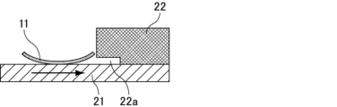
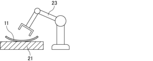
- FIG. 1 to 3 are diagrams for explaining an example in which curling of an optical sheet with a surface protective film causes problems in the process of assembling a device.
- FIG. 1 when the optical sheet 11 with the surface protective film is placed on the base 21 and then the surface protective film is peeled off to expose the optical sheet 12, the curled optical sheet 11 with the surface protective film is , and the base 21 may be difficult to align.
- the curled optical sheet 11 with a surface protection film sometimes did not enter the entrance 22a of the assembly equipment 22 .
- FIG. 3 the curled optical sheet 11 with the surface protective film is difficult to be attracted by the transport robot 23 in some cases.
- the present inventors have found that if the deformation of the optical sheet with a surface protective film after shipment is suppressed, the design of the device assembly process can be optimized based on the optical sheet with a surface protective film at the shipping stage. I thought it would be easier to automate Therefore, there has been a demand for a technique that not only suppresses the occurrence of curl after heat treatment, but also suppresses the increase in the amount of curl over time.
- An object of the present invention is to provide an optical sheet with a surface protective film and a surface protective film that can suppress an increase in curl amount over time.
- the present disclosure 1 is an optical sheet with a surface protective film in which a surface protective film is attached to an optical sheet, wherein the surface protective film has a base layer and an adhesive layer and is fed from a product roll.
- the optical sheet with a surface protection film has a shrinkage rate of 0.70% or less when left for 7 days immediately after.
- Present Disclosure 2 is the optical sheet with a surface protective film according to Present Disclosure 1, wherein the surface protective film has a shrinkage rate of 0.60% or less.
- Present Disclosure 3 is the optical sheet with a surface protective film according to Present Disclosure 1 or 2, wherein the surface protective film has an MD elastic modulus of 620 MPa or more and a TD elastic modulus of 520 MPa or more.
- Present Disclosure 4 is the optical sheet with a surface protective film according to Present Disclosure 3, wherein the surface protective film has an MD elastic modulus of 690 MPa or higher and a TD elastic modulus of 570 MPa or higher.
- Present Disclosure 5 is the optical sheet with a surface protective film according to any one of Present Disclosures 1 to 4, wherein the base layer contains polyethylene.
- Present Disclosure 6 is the optical sheet with a surface protective film of Present Disclosure 5, wherein the substrate layer contains high-density polyethylene.
- Present Disclosure 7 is the optical sheet with a surface protective film according to Present Disclosure 5 or 6, wherein the base material layer has a polyethylene content of 40% by mass or less.
- Present Disclosure 8 is the optical sheet with a surface protective film according to any one of Present Disclosures 1 to 7, wherein the optical sheet is a prism sheet or a diffusion film.
- Present Disclosure 9 is the optical sheet with a surface protective film according to any one of Present Disclosures 1 to 8, wherein the difference between the maximum value and the minimum value of the shrinkage ratio in the film width direction is 0.30% or less.
- the present disclosure 10 is a surface protective film having a base layer and an adhesive layer, and having a shrinkage rate of 0.70% or less when left for 7 days immediately after unwound from a product roll. The present invention will be described in detail below.
- the present inventors investigated the cause of the deformation of the optical sheet with the surface protective film after shipment, and found that the optical sheet is less likely to curl over time. was found to be important in suppressing deformation of an optical sheet with a surface protective film. Furthermore, the present inventors have found that curling of the surface protective film over time can be suppressed by adjusting the composition and manufacturing conditions of the surface protective film, and have completed the present invention.
- the optical sheet with a surface protective film of the present invention is obtained by attaching a surface protective film to an optical sheet.
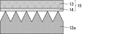
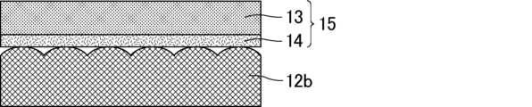
- 4 and 5 are cross-sectional schematic diagrams showing examples of optical sheets with surface protective films.
- the optical sheet may be a prism sheet 12a as shown in FIG. 4, a diffusion film 12b as shown in FIG. 5, or other sheets.
- the surface protection film 15 has the base material layer 13 and the adhesive layer 14, and the optical sheet and the adhesive layer 14 face each other.
- the surface protection film 15 has a shrinkage rate of 0.70% or less when left for 7 days immediately after unwound from the product roll. If the shrinkage rate of the surface protection film 15 when left for 7 days immediately after being unwound from the product roll (hereinafter also referred to as "shrinkage rate after standing") is 0.70% or less, the surface protection film of the present invention is attached. It is possible to sufficiently suppress an increase in the amount of curl in the optical sheet over time.
- the shrinkage after standing is preferably as small as possible, preferably 0%.
- the shrinkage rate after standing is preferably 0.60% or less.
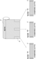
- FIG. 6 is a diagram for explaining a method of measuring the shrinkage rate of the surface protection film.
- the roll-shaped surface protective film (product roll) 15 at the shipping stage shown in FIG. 16C was cut out, and three pairs of marks 17 were attached to both sides of the measurement samples 16A, 16B, and 16C in the longitudinal direction (lengthwise direction of the surface protective film).
- a method of measuring the distance of the mark 17 with a vernier caliper and calculating the shrinkage rate from the average value of the amount of change in the distance can be used.
- the leaving is performed in an indoor normal temperature and normal humidity environment (normal temperature: 20° C. ⁇ 5° C., normal humidity: 45 to 85% RH).
- the glue side (the side facing the adhesive layer) faces upward so that the shrinkage of the surface protection film 15 is not hindered by the adhesive strength of the adhesive layer, and when measuring the distance, The adhesive surface is turned downward so that the measurement samples 16A, 16B, and 16C are free of wrinkles.
- the method for measuring the shrinkage after standing is not particularly limited as long as it can obtain the same result as the above-described measuring method.
- the starting point (initial measurement timing) of the standing period in the measurement of the shrinkage rate after standing is immediately after the product roll (the surface protective film wound into a roll at the time of manufacture) is unwound.
- the timing of the initial measurement is not particularly limited, it is preferably within about 10 days after the production of the surface protection film. Due to the tightness of the rolls, the amount of shrinkage may decrease after a long period of time after manufacture. is.
- the shrinkage rate after standing can be controlled by adjusting the composition of the substrate layer and the pressure-sensitive adhesive layer and the production conditions of the surface protective film. For example, by controlling the cooling rate (temperature profile) of the film immediately after extrusion molding and the tension of the film, it is possible to stabilize the crystal structure of the resin and reduce the strain in the film, thereby reducing the shrinkage rate after standing. can. Further, by controlling the tensile elastic modulus (MD elastic modulus, TD elastic modulus) of the surface protection film within a preferable range, it becomes easy to adjust the shrinkage after standing to 0.70% or less.
- MD elastic modulus, TD elastic modulus tensile elastic modulus
- the difference between the maximum value and the minimum value in the width direction of the product roll (film width direction) in the shrinkage ratio after standing is small. It is preferred that the minimum value difference is 0.30% or less. If the difference between the maximum value and the minimum value of the shrinkage ratio after standing in the film width direction exceeds 0.30%, the shape of the curled film becomes distorted over time, causing more problems during the device assembly process. It may occur more markedly.
- a more preferable range of the difference between the maximum value and the minimum value of the shrinkage ratio after standing in the width direction of the film is within 0.25%, more preferably within 0.20%, and particularly preferably within 0.15%. %.
- the difference between the maximum value and the minimum value of the shrinkage rate after standing in the film width direction is calculated by calculating the average value for each of the measurement samples 16A, 16B, and 16C, and the maximum value and the minimum value of the three average values obtained. can be used.
- the difference between the maximum value and the minimum value of the shrinkage ratio after standing in the film width direction can be achieved, for example, by adjusting the manufacturing conditions. For example, by shortening the distance between the contact points from the die extrusion to the cooling roll and reducing the shrinkage in the width direction of the film, it is possible to suppress the change in the shrinkage rate after leaving the product, especially at the edge and center of the product. can.
- By setting the distance to about 180 mm or less it is possible to reduce the difference between the maximum value and the minimum value of the contraction rate after standing, although it depends on the characteristics of the manufacturing apparatus.
- the set distance is more preferably 150 mm or less, but the lower limit is about 100 mm in terms of equipment settings.
- the difference between the maximum value and the minimum value can be reduced by reducing the average shrinkage rate (preferably 0.20% or less), by increasing the thickness of the edge of the product, by using an air or roll pressing mechanism, etc. There are methods such as improving the degree of adhesion between the cooling roll and the film. In addition, it is possible to physically eliminate the product by slitting the end of the product as large as possible.
- the base material layer is not particularly limited, it preferably contains a polyolefin resin.
- the polyolefin resin is not particularly limited, and conventionally known polyolefin resins can be used, such as polypropylene (PP) and polyethylene (PE).
- the polypropylene may contain 50% by mass or more of propylene units, and examples thereof include homopolypropylene (h-PP), block polypropylene (b-PP), random polypropylene, etc. Among them, block polypropylene is preferred.
- block polypropylene include copolymers of propylene and at least one ⁇ -olefin, and may contain polypropylene blocks and polyethylene blocks.
- the above polyethylene may contain 50% by mass or more of ethylene units, and examples thereof include low density polyethylene (LDPE), high density polyethylene (HDPE, density of 0.942 g/cm 3 or more), and the like.
- the substrate layer preferably contains polyethylene. By including polyethylene, the shrinkage rate and tensile modulus of the surface protection film after standing can be controlled within a desired range, and curling of the surface protection film can be easily suppressed. Among others, it is more preferable that the base material layer contains high-density polyethylene.
- the content of polyethylene in the substrate layer is preferably 40% by mass or less. This makes it easier to control the shrinkage rate and tensile elastic modulus of the surface protection film after standing within a desired range, thereby suppressing the curling of the surface protection film.
- a preferable lower limit of the polyethylene content is 2% by mass, a more preferable lower limit is 10% by mass, a still more preferable lower limit is 20% by mass, and a more preferable upper limit is 30% by mass.
- the content of the high-density polyethylene in the base material layer is preferably 2% by mass or more, and preferably 10% by mass or less.
- the base material layer contains additives such as antistatic agents, release agents, antioxidants, weathering agents, crystal nucleating agents, and resin modifiers, and additives other than polyolefin resins, as long as they do not impair the effects of the present invention. It may contain a resin.
- the substrate layer may be a single layer, or may be a laminate of two or more layers.
- the base material layer may include, for example, a surface layer and an intermediate layer.
- the intermediate layer is preferably formed of a composition containing recovered raw materials. When the intermediate layer is formed of recovered raw materials, manufacturing costs can be reduced, and the environmental load can be reduced.
- the thickness of the base material layer is not particularly limited, but the preferred lower limit is 20 ⁇ m and the preferred upper limit is 200 ⁇ m. When the thickness of the base material layer is within this range, the handleability is excellent. A more preferable lower limit of the thickness of the substrate layer is 25 ⁇ m, and a more preferable upper limit thereof is 100 ⁇ m.
- the pressure-sensitive adhesive layer is not particularly limited
- examples of the base resin include those containing styrene-based elastomers, acrylic-based elastomers, urethane-based elastomers, olefin-based elastomers, and the like.
- styrene-based elastomers are preferable because high adhesive strength (initial adhesive strength) can be exhibited and the hardness can be freely adjusted by adjusting the styrene content.
- the styrene elastomer is not particularly limited, and examples thereof include styrene ethylene propylene styrene block copolymer (SEPS), hydrogenated styrene butadiene rubber (HSBR), styrene ethylene butylene styrene block copolymer (SEBS), styrene ethylene propylene block.
- SEPS styrene ethylene propylene styrene block copolymer
- HSBR hydrogenated styrene butadiene rubber
- SEBS styrene ethylene butylene styrene block copolymer
- SEP styrene ethylene butylene block copolymer
- SEB styrene-isoprene block copolymer
- SI styrene-isoprene-styrene block copolymer
- SB styrene-butadiene block copolymer
- SBS styrene-butadiene-styrene block copolymer
- the pressure-sensitive adhesive layer may contain a tackifier.
- the tackifier include aliphatic copolymers, aromatic copolymers, aliphatic-aromatic copolymers, alicyclic copolymers, alicyclic saturated hydrocarbon resins, liquid aliphatic resins and the like. resins, coumarone-indene-based resins, terpene-based resins, terpene-phenol-based resins, rosin-based resins such as polymerized rosin, (alkyl)phenol-based resins, xylene-based resins, and hydrogenated products thereof. These tackifiers may be used alone or in combination of two or more.
- the content of the tackifier is not particularly limited, but the preferred lower limit is 10 parts by weight, the preferred upper limit is 80 parts by weight, the more preferred lower limit is 20 parts by weight, and the more preferred upper limit is 60 parts by weight, relative to 100 parts by weight of the base resin. Department.
- the pressure-sensitive adhesive layer may contain additives such as a softening agent, an antioxidant, an anti-adhesion agent, and a release agent for the purpose of controlling the adhesive force, if necessary.
- the thickness of the pressure-sensitive adhesive layer is not particularly limited, the preferred lower limit is 2 ⁇ m, and the preferred upper limit is 30 ⁇ m. When the thickness of the pressure-sensitive adhesive layer is within this range, it is possible to achieve both sufficient adhesive strength to an adherend and handleability.
- a more preferable lower limit of the thickness of the adhesive layer is 2.5 ⁇ m, and a more preferable upper limit thereof is 20 ⁇ m.
- the laminated structure of the surface protection film is not particularly limited as long as it includes the substrate layer and the adhesive layer, but one surface is composed of the substrate layer and the other surface is composed of the adhesive layer. It is preferable to have a structure in which the substrate layer and the pressure-sensitive adhesive layer are in direct contact with each other.
- the substrate layer is preferably a layer having a greater thickness than the pressure-sensitive adhesive layer, and the thickness ratio of the substrate layer and the pressure-sensitive adhesive layer (base layer/adhesive layer) is 5 times or more. and more preferably 10 times or more.
- the method for producing the surface protective film is not particularly limited.
- another layer is laminated by a known lamination method such as extrusion lamination or extrusion coating on a layer obtained in advance by T-die molding or inflation molding. and a method in which each layer is made into a film independently and then the obtained films are laminated by dry lamination.
- Co-extrusion molding in which materials are supplied to a multi-layer extruder and molded is preferred, and T-die molding is more preferable from the viewpoint of thickness accuracy.
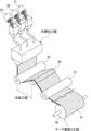
- FIG. 7 is an explanatory diagram showing an example of the manufacturing process of the surface protective film.
- a surface layer composition 31, an intermediate layer composition 32, and an adhesive layer composition 33 are put into hoppers, respectively, and a surface layer, an intermediate layer, and an adhesive layer are formed by a co-extrusion process.
- a multilayer film is produced. After the multilayer film is cooled in a cooling process using cooling rolls 35 and 36, it is wound up in a tape winding process using rolls 37 and 38 to obtain a roll-shaped surface protection film 15.
- FIG. 7 is an explanatory diagram showing an example of the manufacturing process of the surface protective film.
- the multilayer film is cooled by two cooling rolls 35 and 36, which are composed of a casting roll and then a roll in contact with the film.
- the contact time between the multilayer film and the cooling rolls 35 and 36 is not particularly limited as long as it can be picked up and transported without problems such as wrinkles, but from the viewpoint of efficient and stable production, it is about 0.5 to 2 seconds. is preferably Through the cooling process with the cooling rolls 35 and 36, the multilayer film is cooled from room temperature to about 40° C. or less.
- the cooling rate (temperature profile) of the multilayer film can be controlled by the temperature (cooling temperature) of the cooling rolls 35 and 36, etc. By controlling the cooling rate, the resin in the base layer (surface layer and intermediate layer) is reduced.
- Stabilization of the crystal structure can be achieved, and the shrinkage rate after standing can be reduced.
- the temperature of the cooling rolls 35, 36 is preferably set in the range of 20 to 80.degree. C., more preferably 60 to 80.degree.
- the tension of the multilayer film in the cooling step and the winding step is controlled by a tension adjusting mechanism. Also by controlling the tension of the multilayer film, the crystal structure of the resin in the base layer (surface layer and intermediate layer) is stabilized and the strain remaining in the multilayer film is reduced, so that the shrinkage after standing can be reduced. .
- the tension (conveyance tension) of the multilayer film in the cooling step is preferably low from the viewpoint of reducing the shrinkage after standing, but from the viewpoint of stable conveyance of the multilayer film, the preferred lower limit is 20 N/m. and the preferred upper limit is 100 N/m or less.
- the tension (winding tension) of the multilayer film in the winding step is preferably low from the viewpoint of reducing the shrinkage after standing, but from the viewpoint of stable winding of the multilayer film, the preferable lower limit is It is 40 N/m, and the preferred upper limit is 200 N/m or less. In addition, from the viewpoint of reducing the shrinkage ratio after standing, it is preferable to reduce the ratio of the winding tension to the conveying tension (winding tension/conveying tension), and the preferable upper limit is 1.5, and the more preferable upper limit is 2.0, and a more preferable upper limit is 3.0. From the viewpoint of stable transport and winding of the multilayer film, the ratio of the winding tension to the transport tension (winding tension/transport tension) is preferably 1.0 or more.
- the surface protective film preferably has an MD elastic modulus of 620 MPa or higher, more preferably 690 MPa or higher, and still more preferably 740 MPa or higher.
- the upper limit of the MD elastic modulus is not particularly limited, it is, for example, 2000 MPa.
- the surface protection film preferably has a TD elastic modulus of 520 MPa or more, more preferably 570 MPa or more, and even more preferably 620 MPa or more.
- the upper limit of the TD elastic modulus is not particularly limited, it is, for example, 2000 MPa.
- the MD elastic modulus and TD elastic modulus of the surface protection film By controlling the MD elastic modulus and TD elastic modulus of the surface protection film within the above range, it is possible to suppress the increase in curl amount over time, and furthermore, it is possible to greatly suppress the curl amount immediately after sample preparation (initial stage). The amount of curl after standing can be greatly reduced.
- MD means machine direction, and means a direction that matches the extrusion direction of the surface protection film.
- TD means transverse direction, which means a direction perpendicular to MD and parallel to the surface protection film.
- the MD elastic modulus and TD elastic modulus can be measured by a method according to JIS K 7127.
- the MD elastic modulus and the TD elastic modulus can be controlled by adjusting the composition of the base material layer and the pressure-sensitive adhesive layer and the manufacturing conditions of the surface protective film.
- the base material layer contains polyethylene, contains high-density polyethylene, and has a polyethylene content of 40% by mass or less, it is likely to fall within the preferred range described above.
- the surface protective film is usually wound into a roll at the shipping stage.
- a preferable winding length of the roll of the surface protective film is 1000 m or more. From the viewpoint of the switching frequency of users, the longer one is preferable, and 1500 m or more is preferable.
- the use of the surface protective film is not particularly limited, but it is preferably used for surface protection of optical sheets.
- optical sheets include prism sheets (brightness enhancement film, BEF), diffusion films, retardation films, polarizing films, transparent conductive films, etc.
- prism sheets and diffusion films are preferably used. be done.
- the composition of the optical sheet include cycloolefin resin, polyethylene terephthalate (PET), acrylic resin (PMMA), polycarbonate (PC), etc.
- PET is preferably used.
- the surface protective film used in the optical sheet with a surface protective film of the present invention is also one aspect of the present invention. That is, a surface protective film having a base material layer and an adhesive layer and having a shrinkage rate of 0.70% or less when left for 7 days immediately after being unwound from the product roll is also one aspect of the present invention. .
- the surface protection film and the optical sheet with a surface protection film which can suppress the increase in the amount of curls with time can be provided.
- FIG. 4 is a diagram for explaining a first example in which curling of an optical sheet with a surface protective film causes problems in a device assembly process
- FIG. 10 is a diagram for explaining a second example in which curling of an optical sheet with a surface protection film causes problems in a device assembly process
- FIG. 10 is a diagram for explaining a third example in which the curling of the optical sheet with the surface protection film causes problems in the device assembly process.
- It is a cross-sectional schematic diagram which shows an example of an optical sheet with a surface protective film.
- It is a cross-sectional schematic diagram which shows another example of an optical sheet with a surface protective film.
- It is a figure for demonstrating the measuring method of the shrinkage
- It is explanatory drawing which shows an example of the manufacturing process of a surface protection film.
- b-PP PE-containing block polypropylene
- h-PP homopolypropylene
- LDPE low density polyethylene
- HDPE high density polyethylene
- Example 1 Manufacture of surface protective film As shown in Fig. 4, a surface protective film with a total thickness of 30 ⁇ m (base layer thickness: 27.5 ⁇ m, adhesive layer thickness: 2.5 ⁇ m) is produced by a T-die co-extrusion method. manufactured. Specifically, 100 parts by weight of b-PP was used as the surface layer composition 31, and 75 parts by weight of b-PP, 22.5 parts by weight of LDPE, and 2.5 parts by weight of HDPE were used as the intermediate layer composition 32.
- a mixture of 100 parts by mass of SEBS ("G1657” manufactured by Kraton) and 20 parts by mass of a tackifier ("Alcon P100" manufactured by Arakawa Chemical Co., Ltd.) is used as the adhesive layer composition 33, and the thickness of each surface layer is was 6 ⁇ m, the thickness of the intermediate layer was 21.5 ⁇ m, and the thickness of the adhesive layer was 2.5 ⁇ m.
- the surface layer and the intermediate layer correspond to base layers.
- the raw materials of the base layer and the PE content in the base layer are shown in Table 1 below.
- the multilayer film produced in the coextrusion process was cooled in the cooling process and then wound up in the tape winding process to obtain a roll-shaped surface protective film 15 having a width of 800 mm and a length of 2000 m.
- the cooling step by passing through two cooling rolls 36 adjusted to a surface temperature of 30°C, the film was cooled from about 200°C immediately after co-extrusion to about 40°C in about 6 seconds.
- the tension adjustment mechanism adjusts the tension of the multilayer film (conveyance tension) to 60 N/m in the cooling process, and adjusts the tension of the multilayer film (winding tension) to 90 N/m in the tape winding process.
- the ratio (winding tension/conveying tension) was set to 1.5.
- the distance between the mold exit and the grounding point of the cooling roll was set to about 200 mm, but was set to 150 mm only in Example 9, which will be described later.
- the tensile modulus of the obtained surface protection film was measured in each of the MD and TD directions according to JIS K7127. Specifically, a strip-shaped surface protective film cut into a width of 10 mm and a length of 150 mm was subjected to a tensile test at a rate of 500 mm/min using a universal tensile tester Tensilon to measure the tensile modulus. Table 1 shows the results.
- the glue side (the side facing the adhesive layer) faces upward so that the shrinkage of the surface protection film 15 is not hindered by the adhesive strength of the adhesive layer, and when measuring the distance, The adhesive surface was directed downward so that the measurement samples 16A, 16B, and 16C were free of wrinkles.
- the contraction rate was measured according to the following procedures (A) to (G).
- (A) A total of three measurement samples 16A, 16B, and 16C were cut out from different portions of the surface protective film 15 in the width direction.
- the size of the measurement samples 16A, 16B, and 16C was about 250 mm long ⁇ 60 mm wide.
- the three measurement samples 16A, 16B, and 16C were cut out one by one from both ends and the center in the width direction of the roll-shaped surface protective film 15 .
- the measurement samples 16A and 16C cut out from the ends are portions corresponding to the regions 60 mm from the ends of the roll-shaped surface protection film 15, and the measurement sample 16B cut out from the central portion.
- a prism sheet having a PET film with a width of 800 mm and a thickness of 75 ⁇ m as a base material and a prism shape with a height of about several tens of ⁇ m made of acrylic resin is formed on the base material.
- This prism sheet and the obtained surface protection film were pasted together by a laminator machine.
- the tension of the prism sheet was set to 225 N/m, and the tension of the surface protective film was set to 50 N/m. Obtained.
- the bonding was performed at a pressure of 0.2 MPa and a bonding speed of 1 m/min.
- Examples 2 to 9, Comparative Examples 1 to 5 An optical sheet with a surface protective film was produced in the same manner as in Example 1, except that the composition of the substrate layer and the thickness of the surface protective film were changed as shown in Table 1 below.
- the composition of the base layer was adjusted by changing the compositions of the surface layer composition and the intermediate layer composition.
- the surface protection film and the optical sheet with a surface protection film which can suppress the increase in the amount of curls with time can be provided.
- Optical sheet with surface protective film 12 Optical sheet 12a: Prism sheet 12b: Diffusion film 13: Base layer 14: Adhesive layer 15: Surface protective films 16A, 16B, 16C: Sample for measurement 17: Mark 21: Base 22: Assembly equipment 22a: Entrance 23: Transfer robot 31: Surface layer composition 32: Intermediate layer composition 33: Adhesive layer composition 35, 36: Cooling rolls 37, 38: Rolls
Landscapes
- Chemical & Material Sciences (AREA)
- Organic Chemistry (AREA)
- Physics & Mathematics (AREA)
- General Physics & Mathematics (AREA)
- Optics & Photonics (AREA)
- Engineering & Computer Science (AREA)
- Mechanical Engineering (AREA)
- Chemical Kinetics & Catalysis (AREA)
- Laminated Bodies (AREA)
- Adhesive Tapes (AREA)
Priority Applications (3)
| Application Number | Priority Date | Filing Date | Title |
|---|---|---|---|
| KR1020237041491A KR20240111704A (ko) | 2021-11-17 | 2022-11-16 | 표면 보호 필름이 부착된 광학 시트 및 표면 보호 필름 |
| CN202280043988.2A CN117529404A (zh) | 2021-11-17 | 2022-11-16 | 带表面保护膜的光学片、及表面保护膜 |
| JP2023521963A JPWO2023090358A1 (cg-RX-API-DMAC7.html) | 2021-11-17 | 2022-11-16 |
Applications Claiming Priority (2)
| Application Number | Priority Date | Filing Date | Title |
|---|---|---|---|
| JP2021-187314 | 2021-11-17 | ||
| JP2021187314 | 2021-11-17 |
Publications (1)
| Publication Number | Publication Date |
|---|---|
| WO2023090358A1 true WO2023090358A1 (ja) | 2023-05-25 |
Family
ID=86397054
Family Applications (1)
| Application Number | Title | Priority Date | Filing Date |
|---|---|---|---|
| PCT/JP2022/042546 Ceased WO2023090358A1 (ja) | 2021-11-17 | 2022-11-16 | 表面保護フィルム付き光学シート、及び、表面保護フィルム |
Country Status (5)
| Country | Link |
|---|---|
| JP (1) | JPWO2023090358A1 (cg-RX-API-DMAC7.html) |
| KR (1) | KR20240111704A (cg-RX-API-DMAC7.html) |
| CN (1) | CN117529404A (cg-RX-API-DMAC7.html) |
| TW (1) | TWI924960B (cg-RX-API-DMAC7.html) |
| WO (1) | WO2023090358A1 (cg-RX-API-DMAC7.html) |
Citations (5)
| Publication number | Priority date | Publication date | Assignee | Title |
|---|---|---|---|---|
| JP2006219520A (ja) * | 2005-02-08 | 2006-08-24 | Nitto Denko Corp | 表面保護シート、およびその製造方法 |
| WO2010084783A1 (ja) * | 2009-01-26 | 2010-07-29 | 積水化学工業株式会社 | プリズムシート用表面保護フィルム、およびその製造方法、およびそれが貼り付けられたプリズムシート |
| JP2010229328A (ja) * | 2009-03-27 | 2010-10-14 | Gunze Ltd | 表面保護フィルム |
| JP2015189909A (ja) * | 2014-03-28 | 2015-11-02 | 積水化学工業株式会社 | 表面保護フィルム |
| JP2017160410A (ja) * | 2016-03-03 | 2017-09-14 | 東レフィルム加工株式会社 | 積層フィルム |
Family Cites Families (4)
| Publication number | Priority date | Publication date | Assignee | Title |
|---|---|---|---|---|
| JP2005239798A (ja) * | 2004-02-25 | 2005-09-08 | Toyobo Co Ltd | 耐熱性の改善された熱収縮性ポリオレフィン系フィルム |
| JP2008102271A (ja) * | 2006-10-18 | 2008-05-01 | Nitto Denko Corp | 表面保護フィルムおよび表面保護フィルム付き光学フィルム |
| WO2018217053A1 (ko) * | 2017-05-26 | 2018-11-29 | 에스케이씨 주식회사 | 광학용 폴리에스테르 필름 및 이를 포함하는 프리즘 시트 또는 편광 반사 시트 |
| JP7292884B2 (ja) | 2019-01-18 | 2023-06-19 | 東レフィルム加工株式会社 | 表面保護フィルム |
-
2022
- 2022-11-16 KR KR1020237041491A patent/KR20240111704A/ko active Pending
- 2022-11-16 JP JP2023521963A patent/JPWO2023090358A1/ja active Pending
- 2022-11-16 CN CN202280043988.2A patent/CN117529404A/zh active Pending
- 2022-11-16 WO PCT/JP2022/042546 patent/WO2023090358A1/ja not_active Ceased
- 2022-11-17 TW TW111143924A patent/TWI924960B/zh active
Patent Citations (5)
| Publication number | Priority date | Publication date | Assignee | Title |
|---|---|---|---|---|
| JP2006219520A (ja) * | 2005-02-08 | 2006-08-24 | Nitto Denko Corp | 表面保護シート、およびその製造方法 |
| WO2010084783A1 (ja) * | 2009-01-26 | 2010-07-29 | 積水化学工業株式会社 | プリズムシート用表面保護フィルム、およびその製造方法、およびそれが貼り付けられたプリズムシート |
| JP2010229328A (ja) * | 2009-03-27 | 2010-10-14 | Gunze Ltd | 表面保護フィルム |
| JP2015189909A (ja) * | 2014-03-28 | 2015-11-02 | 積水化学工業株式会社 | 表面保護フィルム |
| JP2017160410A (ja) * | 2016-03-03 | 2017-09-14 | 東レフィルム加工株式会社 | 積層フィルム |
Also Published As
| Publication number | Publication date |
|---|---|
| JPWO2023090358A1 (cg-RX-API-DMAC7.html) | 2023-05-25 |
| CN117529404A (zh) | 2024-02-06 |
| KR20240111704A (ko) | 2024-07-17 |
| TW202330270A (zh) | 2023-08-01 |
| TWI924960B (zh) | 2026-05-11 |
Similar Documents
| Publication | Publication Date | Title |
|---|---|---|
| CN102834339B (zh) | 剥离方法以及剥离装置 | |
| JP5540669B2 (ja) | ロール状巻回体 | |
| JP6593168B2 (ja) | 加熱工程用表面保護フィルム | |
| WO2011129167A1 (ja) | 表面保護フィルム | |
| CN103576363B (zh) | 光学显示面板的制造方法和光学显示面板的制造系统 | |
| JP2010214853A (ja) | プリズムシート用表面保護シート | |
| CN103261352A (zh) | 粘合性树脂组合物及粘合膜 | |
| JP4904525B2 (ja) | 表面保護フィルム | |
| JP5360723B2 (ja) | 表面保護フィルム | |
| KR102363884B1 (ko) | 복층 필름 및 권회체 | |
| CN108541338A (zh) | 晶片加工用带 | |
| TWI747985B (zh) | 切割片 | |
| TWI924960B (zh) | 附有表面保護膜之光學片、及表面保護膜 | |
| JP2010111721A (ja) | 表面保護フィルム | |
| CN102712831A (zh) | 表面保护膜及其制造方法、以及表面保护用基材膜及其制造方法 | |
| CN114456748B (zh) | 一种粘着组合物及自粘保护膜 | |
| JP6872774B2 (ja) | クリーニングシート | |
| WO2015194059A1 (ja) | 自己粘着性表面保護フィルム | |
| JP2009241487A (ja) | 表面保護フィルム | |
| KR101254718B1 (ko) | 엠보 보호필름 및 그의 제조방법 | |
| JP2004268328A (ja) | 光学部品保護シートの製造方法 | |
| JP2016196650A (ja) | 粘着剤及び粘着フィルム | |
| JP6996859B2 (ja) | 粘着テープロール | |
| JP2005028618A (ja) | 表面保護フィルムの製造方法 | |
| JP2005028619A (ja) | 表面保護フィルム |
Legal Events
| Date | Code | Title | Description |
|---|---|---|---|
| WWE | Wipo information: entry into national phase |
Ref document number: 2023521963 Country of ref document: JP |
|
| 121 | Ep: the epo has been informed by wipo that ep was designated in this application |
Ref document number: 22895639 Country of ref document: EP Kind code of ref document: A1 |
|
| WWE | Wipo information: entry into national phase |
Ref document number: 202280043988.2 Country of ref document: CN |
|
| 122 | Ep: pct application non-entry in european phase |
Ref document number: 22895639 Country of ref document: EP Kind code of ref document: A1 |