WO2023079896A1 - Dispositif de détection d'accélération - Google Patents
Dispositif de détection d'accélération Download PDFInfo
- Publication number
- WO2023079896A1 WO2023079896A1 PCT/JP2022/037390 JP2022037390W WO2023079896A1 WO 2023079896 A1 WO2023079896 A1 WO 2023079896A1 JP 2022037390 W JP2022037390 W JP 2022037390W WO 2023079896 A1 WO2023079896 A1 WO 2023079896A1
- Authority
- WO
- WIPO (PCT)
- Prior art keywords
- substrate
- acceleration detection
- rigidity
- detection device
- view
- Prior art date
Links
- 230000001133 acceleration Effects 0.000 title claims abstract description 199
- 238000001514 detection method Methods 0.000 title claims abstract description 171
- 239000000758 substrate Substances 0.000 claims abstract description 136
- 238000007789 sealing Methods 0.000 claims abstract description 56
- 230000005484 gravity Effects 0.000 claims abstract description 33
- 229920005989 resin Polymers 0.000 claims abstract description 9
- 239000011347 resin Substances 0.000 claims abstract description 9
- 230000002093 peripheral effect Effects 0.000 claims description 19
- 239000000463 material Substances 0.000 description 30
- 230000000052 comparative effect Effects 0.000 description 19
- 238000009434 installation Methods 0.000 description 5
- 238000010586 diagram Methods 0.000 description 4
- 230000004048 modification Effects 0.000 description 4
- 238000012986 modification Methods 0.000 description 4
- 239000011810 insulating material Substances 0.000 description 3
- 229910052751 metal Inorganic materials 0.000 description 3
- 239000002184 metal Substances 0.000 description 3
- 239000004593 Epoxy Substances 0.000 description 2
- XEEYBQQBJWHFJM-UHFFFAOYSA-N Iron Chemical compound [Fe] XEEYBQQBJWHFJM-UHFFFAOYSA-N 0.000 description 2
- PXHVJJICTQNCMI-UHFFFAOYSA-N Nickel Chemical compound [Ni] PXHVJJICTQNCMI-UHFFFAOYSA-N 0.000 description 2
- 239000000853 adhesive Substances 0.000 description 2
- 230000001070 adhesive effect Effects 0.000 description 2
- PNEYBMLMFCGWSK-UHFFFAOYSA-N aluminium oxide Inorganic materials [O-2].[O-2].[O-2].[Al+3].[Al+3] PNEYBMLMFCGWSK-UHFFFAOYSA-N 0.000 description 2
- 239000000919 ceramic Substances 0.000 description 2
- 238000006073 displacement reaction Methods 0.000 description 2
- 239000011521 glass Substances 0.000 description 2
- 238000004519 manufacturing process Methods 0.000 description 2
- 229910000679 solder Inorganic materials 0.000 description 2
- 239000004925 Acrylic resin Substances 0.000 description 1
- 229920000178 Acrylic resin Polymers 0.000 description 1
- 229910045601 alloy Inorganic materials 0.000 description 1
- 239000000956 alloy Substances 0.000 description 1
- 229910052782 aluminium Inorganic materials 0.000 description 1
- XAGFODPZIPBFFR-UHFFFAOYSA-N aluminium Chemical compound [Al] XAGFODPZIPBFFR-UHFFFAOYSA-N 0.000 description 1
- 230000000694 effects Effects 0.000 description 1
- 239000003822 epoxy resin Substances 0.000 description 1
- 229910052742 iron Inorganic materials 0.000 description 1
- HFGPZNIAWCZYJU-UHFFFAOYSA-N lead zirconate titanate Chemical compound [O-2].[O-2].[O-2].[O-2].[O-2].[Ti+4].[Zr+4].[Pb+2] HFGPZNIAWCZYJU-UHFFFAOYSA-N 0.000 description 1
- 229910052451 lead zirconate titanate Inorganic materials 0.000 description 1
- 239000007769 metal material Substances 0.000 description 1
- 229910052759 nickel Inorganic materials 0.000 description 1
- 229920000647 polyepoxide Polymers 0.000 description 1
- 229920013716 polyethylene resin Polymers 0.000 description 1
- 229920005749 polyurethane resin Polymers 0.000 description 1
- 229920002050 silicone resin Polymers 0.000 description 1
- 230000001629 suppression Effects 0.000 description 1
- 229920005992 thermoplastic resin Polymers 0.000 description 1
- 229920001187 thermosetting polymer Polymers 0.000 description 1
Images


Classifications
-
- G—PHYSICS
- G01—MEASURING; TESTING
- G01P—MEASURING LINEAR OR ANGULAR SPEED, ACCELERATION, DECELERATION, OR SHOCK; INDICATING PRESENCE, ABSENCE, OR DIRECTION, OF MOVEMENT
- G01P15/00—Measuring acceleration; Measuring deceleration; Measuring shock, i.e. sudden change of acceleration
- G01P15/02—Measuring acceleration; Measuring deceleration; Measuring shock, i.e. sudden change of acceleration by making use of inertia forces using solid seismic masses
- G01P15/08—Measuring acceleration; Measuring deceleration; Measuring shock, i.e. sudden change of acceleration by making use of inertia forces using solid seismic masses with conversion into electric or magnetic values
Definitions
- the present invention relates to an acceleration detection device for detecting vibration of an object.
- Japanese Unexamined Patent Application Publication No. 2002-200002 discloses an acceleration detection device that detects the acceleration of a vehicle.
- an acceleration detection element and circuit components are mounted on one surface of a substrate. The other surface of the substrate is fixed to the object to be detected.
- the sensor section is arranged in a housing composed of a wiring board and a lid.
- the housing is arranged on the circuit board with a space therebetween.
- the housing is supported on the circuit board by a housing support made of a low-rigidity material.
- a space between the housing and the circuit board is connected to the external environment via an orifice or the like. This is intended to improve vibration resistance.
- JP 2011-75442 A Japanese Patent Application Laid-Open No. 2011-38908
- An object of the present invention is to provide an acceleration detection device that can be miniaturized and capable of detecting high-frequency acceleration with high precision.
- An acceleration detection device includes a substrate including a first main surface and a second main surface facing each other; an acceleration detection element mounted on the first main surface of the substrate; A circuit component mounted on at least the second main surface of the first main surface and the second main surface of the substrate, and the acceleration detection element provided on the first main surface of the substrate.
- an acceleration detection device that can be miniaturized and that can detect high-frequency acceleration with high precision.
- FIG. 1 is a schematic perspective view for explaining an acceleration detection device according to a first embodiment of the invention.
- FIG. 2 is a schematic perspective view of the acceleration detection device according to the first embodiment of the present invention, viewed from the second main surface side of the substrate.
- FIG. 3 is a schematic cross-sectional view along line II in FIG.
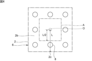
- FIG. 4 is a schematic plan view showing the positional relationship between the substrate and the high-rigidity member in the first embodiment of the present invention.
- FIG. 5 is a schematic front sectional view of the acceleration detection device of the first comparative example.
- FIG. 6 is a schematic front cross-sectional view of an acceleration detection device of a second comparative example.
- FIG. 1 is a schematic perspective view for explaining an acceleration detection device according to a first embodiment of the invention.
- FIG. 2 is a schematic perspective view of the acceleration detection device according to the first embodiment of the present invention, viewed from the second main surface side of the substrate.
- FIG. 3 is a schematic cross-sectional view along line
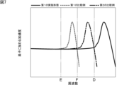
- FIG. 7 is a diagram showing the relationship between frequency and acceleration for explaining the range of frequencies in which acceleration can be detected in the first embodiment, first comparative example, and second comparative example of the present invention; is.
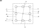
- FIG. 8 is a schematic plan view for explaining an example of four regions in the first embodiment of the invention.
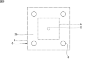
- FIG. 9 is a schematic plan view showing the positional relationship between the substrate and the high-rigidity member in the modification of the first embodiment of the present invention.
- FIG. 10 is a diagram showing the relationship between the total installation area of a plurality of high-rigidity members, the number of high-rigidity members, and the resonance frequency of the entire structure of the acceleration detection device.
- FIG. 8 is a schematic plan view for explaining an example of four regions in the first embodiment of the invention.
- FIG. 9 is a schematic plan view showing the positional relationship between the substrate and the high-rigidity member in the modification of the first embodiment of the present invention.
- FIG. 10 is a diagram showing the relationship between the total installation area of
- FIG. 11 is a schematic plan view showing the positional relationship between the substrate and the high-rigidity member in the second embodiment of the present invention.
- FIG. 12 is a schematic plan view showing the positional relationship between the substrate and the high-rigidity member in the third embodiment of the invention.
- FIG. 13 is a schematic plan view showing the positional relationship between the substrate and the high-rigidity member in the fourth embodiment of the invention.
- FIG. 14 is a schematic front sectional view of an acceleration detection device according to a fourth embodiment of the invention.
- FIG. 15 is a perspective view of an example of an acceleration detection element.
- FIG. 16 is a perspective view for explaining the internal structure of one example of the acceleration detection element.
- FIG. 17 is a perspective view of an example of an acceleration detection element.
- FIG. 18 is a perspective view for explaining the internal structure of one example of the acceleration detection element.
- FIG. 19 is a schematic perspective view for explaining an acceleration detection device according to a fifth embodiment of the invention.
- FIG. 1 is a schematic perspective view for explaining the acceleration detection device according to the first embodiment of the present invention.
- FIG. 2 is a schematic perspective view of the acceleration detection device according to the first embodiment, viewed from the second main surface side of the substrate.
- FIG. 3 is a schematic cross-sectional view along line II in FIG. In FIG. 3, each element is shown schematically by adding two diagonal lines to a rectangle.
- the acceleration detection device 1 has a substrate 2 as shown in FIGS.
- the shape of the substrate 2 is square in plan view.
- the shape of the substrate 2 in plan view is not limited to the above, and may be, for example, a rectangle or another polygon.
- planar view refers to a direction viewed from above in FIG.
- the substrate 2 has a first main surface 2a and a second main surface 2b.
- the first main surface 2a and the second main surface 2b face each other.
- the substrate 2 is made of, for example, an insulating material such as glass epoxy or alumina.
- the first main surface 2a and the second main surface 2b of the substrate 2 are provided with wiring and the like for electrical connection.
- the acceleration detection device 1 has an acceleration detection element 3, a plurality of circuit components, and a plurality of high-rigidity members 8.
- the multiple circuit components include multiple first circuit components 4 and multiple second circuit components 5 .
- the acceleration detection element 3 is mounted on the first principal surface 2 a of the substrate 2 .
- the acceleration detection element 3 is an element that detects acceleration applied to the acceleration detection device 1 .
- the acceleration detection element 3 outputs an electrical signal corresponding to the magnitude of the applied acceleration.
- a plurality of first circuit components 4 are mounted on the first main surface 2 a of the substrate 2 .
- a plurality of second circuit components 5 are mounted on the second main surface 2b.
- the first circuit component 4 and the second circuit component 5 are electrically connected to each other.
- the first circuit component 4 and the second circuit component 5 constitute an electric circuit for driving the acceleration detection element 3 and for outputting signals from the acceleration detection element 3 .
- the circuit component should just be provided in the 2nd main surface 2b at least among the 1st main surface 2a and the 2nd main surface 2b.
- a main body 6 of the acceleration detection device 1 is composed of the board 2 , the acceleration detection element 3 , the plurality of first circuit components 4 and the plurality of second circuit components 5 .
- the acceleration detection element 3 is positioned at the center of the first main surface 2a of the substrate 2.
- the center of gravity of the body portion 6 is positioned at the center of the substrate 2 .
- the positions of the acceleration detecting element 3, each first circuit component 4 and each second circuit component 5 are not particularly limited.
- the position of the center of gravity of the body portion 6 is not limited to the above either.
- the acceleration detection device 1 has a sealing member 10.
- the sealing member 10 is made of resin.
- the sealing member 10 has a first sealing portion 11 and a second sealing portion 12 .
- the first sealing portion 11 is provided on the first main surface 2 a of the substrate 2 .
- the first sealing portion 11 covers the acceleration detection element 3 and the plurality of first circuit components 4 .
- the second sealing portion 12 is provided on the second main surface 2b.
- the second sealing portion 12 covers the plurality of second circuit components 5 .
- a sealing member 10 seals the acceleration detection element 3 , the plurality of first circuit components 4 , and the plurality of second circuit components 5 in the acceleration detection device 1 .
- the second sealing portion 12 has a first surface 12a and a second surface 12b.
- the first surface 12a and the second surface 12b face each other.
- First surface 12 a faces second main surface 2 b of substrate 2 .
- the second surface 12b is a surface located outside the acceleration detection device 1.
- the second surface 12b is fixed to the detection object 13 of the acceleration detection device 1.
- the second surface 12b is the mounting surface of the acceleration detection device 1. As shown in FIG.
- thermosetting resin such as epoxy resin, silicone resin or polyurethane resin, or thermoplastic resin such as acrylic resin or polyethylene resin can be used.
- a plurality of high-rigidity members 8 are provided inside the second sealing portion 12 of the sealing member 10 .
- a plurality of high-rigidity members 8 extend in a direction connecting the second surface 12 b of the second sealing portion 12 and the second main surface 2 b of the substrate 2 .
- the high-rigidity member 8 is made of a material having higher rigidity than the sealing member 10 .
- the high-rigidity member 8 consists of a cylindrical metal pin.
- the high-rigidity member 8 is not limited to a columnar shape, and may be a columnar body of any shape.
- the metal material of the high-rigidity member 8 for example, at least one metal selected from the group consisting of iron, aluminum, nickel, and alloys mainly composed of these can be used. However, appropriate ceramics can also be used as the material of the high-rigidity member 8 . At least one high-rigidity member 8 may be provided.
- FIG. 4 is a schematic plan view showing the positional relationship between the substrate and the high-rigidity member in the first embodiment.
- components other than the substrate 2 and the high-rigidity member 8 are omitted. The same applies to other schematic plan views.
- eight high-rigidity members 8 are provided.
- the plurality of high-rigidity members 8 are positioned outside the center of gravity O of the main body 6 in plan view. More specifically, the multiple high-rigidity members 8 surround the center of gravity O in plan view.
- each of the plurality of high-rigidity members 8 is joined to the second main surface 2b of the substrate 2 with a conductive joining material 9a.
- the plurality of high-rigidity members 8 electrically connect the wiring provided on the substrate 2, the acceleration detecting element 3, the plurality of first circuit components 4, and the plurality of second circuit components 5 through the conductive bonding material 9a. properly connected.
- the plurality of high-rigidity members 8 may not necessarily be electrically connected to the acceleration detection element 3, the plurality of first circuit components 4, and the plurality of second circuit components 5.
- An appropriate conductive bonding material such as solder or a conductive adhesive can be used for the conductive bonding material 9a.
- An insulating bonding material may be used instead of the conductive bonding material 9a.
- the ends of the plurality of high-rigidity members 8 farther from the substrate 2 are joined to the mounting surface 13a of the detection object 13 via the joining material 9b.
- the acceleration detection device 1 is fixed to the detection object 13 .
- the bonding material 9b may be a conductive bonding material or a non-conductive bonding material.
- a first feature of the acceleration detection device 1 is that the acceleration detection element 3 is mounted on the first main surface 2a of the substrate 2, and the second circuit component 5 is mounted on the second main surface 2b of the substrate 2. There is As a result, the area of the portion of the substrate 2 where the circuit components are provided can be reduced, and the acceleration detection device 1 can be miniaturized. In addition, it is preferable that circuit components are provided on both the first main surface 2a and the second main surface 2b of the substrate 2 as in the present embodiment. As a result, the acceleration detection device 1 can be made even more compact.
- a second feature of the acceleration detection device 1 is that the high-rigidity member 8 is composed of the substrate 2, the acceleration detection element 3, the first circuit component 4, and the second circuit component 5. are also located outside in plan view. As a result, vibration in the acceleration detection device 1 can be suppressed, and high-frequency acceleration can be detected with high accuracy. This will be described below with reference to a first comparative example and a second comparative example in addition to the present embodiment.
- a first comparative example shown in FIG. 5 differs from the first embodiment in that it does not have a high-rigidity member 8 .
- the second comparative example shown in FIG. 6 differs from the first embodiment in that there is one high-rigidity member 8 and that the high-rigidity member 8 overlaps the center of gravity of the main body 6 in plan view. .
- FIG. 7 is a diagram showing the relationship between frequency and acceleration for explaining the frequency range over which acceleration can be detected in the first embodiment, first comparative example, and second comparative example.
- the acceleration applied to the element does not substantially depend on the frequency at frequencies lower than the frequency indicated by the two-dot chain line D.
- the acceleration depends on the frequency. Therefore, at frequencies higher than the two-dot chain line D, the detected acceleration is affected by the frequency, and the accuracy of detection is lowered. Therefore, in the first embodiment, acceleration can be detected with high accuracy in a frequency range lower than the frequency indicated by the two-dot chain line D.
- acceleration can be preferably detected in a frequency range lower than the frequency indicated by the two-dot chain line E.
- acceleration can be preferably detected in a frequency range lower than the frequency indicated by the two-dot chain line F.
- the frequency indicated by the two-dot chain line D is higher than the frequencies indicated by the two-dot chain lines E and F. Therefore, it can be seen that in the first embodiment, acceleration can be detected with high accuracy at frequencies higher than those in the first and second comparative examples. The reason for this will be explained below.
- the acceleration applied to the element has a maximum value at frequencies higher than the two-dot chain line E. This is because the entire structure of the acceleration detection device resonates.
- the frequency at which the acceleration has a maximum value in FIG. 7 schematically shows the resonance frequency of the entire structure of the acceleration detection device when the acceleration detection device is fixed to the detection object 13 .
- the acceleration detection device is fixed to the detection object 13 by the sealing member 10 . Since the sealing member 10 is made of resin, it has low rigidity. Furthermore, as indicated by arrow B, the entire structure of the acceleration detection device easily vibrates in directions substantially parallel to the first main surface 2 a and the second main surface 2 b of the substrate 2 . Therefore, in the first comparative example, the resonance frequency of the entire structure of the acceleration detection device is low.
- a high-rigidity member 8 is provided in the second comparative example. Therefore, the resonance frequency of the entire structure of the acceleration detection device is increased. However, as indicated by arrow C, suppression of vibration in the direction substantially parallel to the first main surface 2a and the second main surface 2b of the substrate 2 is insufficient. Therefore, although the resonance frequency of the entire structure of the acceleration detection device in the second comparative example is higher than that in the first comparative example, it is not sufficiently high.
- the plurality of high-rigidity members 8 are positioned outside the center of gravity of the main body 6 in plan view.
- the entire acceleration detection device 1 can be favorably supported by the high-rigidity member 8 .
- the vibration in the direction substantially parallel to the first main surface 2a and the second main surface 2b of the substrate 2 can be suppressed.
- the rigidity of the high-rigidity member 8 is higher than that of the sealing member 10 . Therefore, the resonance frequency of the entire structure of the acceleration detection device 1 can be effectively increased, and high-frequency acceleration can be detected with high accuracy.
- the plurality of high-rigidity members 8 be positioned on the outer peripheral side of the substrate 2 . More specifically, the plurality of high-rigidity members 8 are located outside the area indicated by the two-dot chain line A in FIG. When the distance between the center of gravity O of the main body 6 and the outer peripheral edge of the substrate 2 is L, the two-dot chain line A is a line connecting the points at a distance of 1/2 of the distance L.
- the outer peripheral edge of the substrate 2 includes a plurality of facing portions 2c.
- the facing portion 2c is located on a straight line connecting the center of gravity O and the high-rigidity member 8, sandwiches the high-rigidity member 8 together with the center of gravity O, and faces the center of gravity O.
- the substrate 2 has eight opposing portions 2c.
- the distance between the center of gravity O and the center of the high-rigidity member 8 is 1/2 times the distance L between the center of gravity O of the body portion 6 and the facing portion 2c. It is preferable that it is above.
- the entire acceleration detection device 1 can be effectively supported by the high-rigidity member 8 .
- the vibration in the direction substantially parallel to the first main surface 2a and the second main surface 2b of the substrate 2 can be effectively suppressed. Therefore, high-frequency acceleration can be detected with even higher accuracy.
- FIG. 8 is a schematic plan view for explaining an example of four regions in the first embodiment.
- the straight lines G and H in FIG. 8 are examples, and the directions of the straight lines G and H are arbitrary.
- the straight line G and the straight line H should be orthogonal to each other.
- dashed lines K in FIG. 8 are lines connecting the centers of the plurality of high-rigidity members 8 .
- first region J1 in a plan view, four regions bounded by two straight lines G and H that pass through the center of gravity O of the main body 6 and are perpendicular to each other are defined as a first region J1 and a second region J1.
- the first region J1 is adjacent to the second region J2 and the fourth region J4, and is not adjacent to the third region J3.
- the high-rigidity members 8 are positioned in both the first area J1 and the third area J3.
- the plurality of high-rigidity members 8 include at least one pair of high-rigidity members 8 located in two non-adjacent regions among the four regions.
- the acceleration detection device 1 as a whole can be supported by at least one pair of high-rigidity members 8 in regions facing each other with the center of gravity O therebetween. Thereby, the vibration in the direction substantially parallel to the first main surface 2a and the second main surface 2b of the substrate 2 can be effectively suppressed.
- At least one pair of high-rigidity members 8 located in the first region J1 and the third region J3 are opposed to each other with the center of gravity O of the main body 6 interposed therebetween. Thereby, the vibration in the direction substantially parallel to the first main surface 2a and the second main surface 2b of the substrate 2 can be suppressed more effectively.
- At least one high-rigidity member 8 is positioned in each of the first region J1, the second region J2, the third region J3, and the fourth region J4, as in the first embodiment. is more preferred.
- the acceleration detection device 1 as a whole can be supported by at least one pair of high-rigidity members 8 in each of two sets of regions facing each other across the center of gravity O of the main body 6 . Thereby, the vibration in the direction substantially parallel to the first main surface 2a and the second main surface 2b of the substrate 2 can be further suppressed.
- At least one pair of high-rigidity members 8 located in the first region J1 and the third region J3 are opposed to each other with the center of gravity O of the main body 6 interposed therebetween.
- at least one pair of high-rigidity members 8 located in the second region J2 and the fourth region J4 are opposed to each other with the center of gravity O interposed therebetween.
- the straight lines G and H need only be orthogonal to each other, and the directions of the straight lines G and H are arbitrary.
- the positions of the four regions are determined by straight lines G and H in arbitrary directions.
- the positions of the above-described four regions bounded by any one of the straight lines G and H in any direction and the positions of the plurality of high-rigidity members 8 have any of the above relationships. is preferred. Note that the above four regions are established even when the shape of the substrate 2 in a plan view is other than a square. Therefore, it is preferable that the positions of the four regions and the positions of the plurality of high-rigidity members 8 have any of the above relationships regardless of the shape of the substrate 2 in plan view.
- the shape of the portion surrounded by the lines connecting the centers of the multiple high-rigidity members 8 is a square. More specifically, the shape of the portion surrounded by the lines connecting the centers of the plurality of high-rigidity members 8 with the maximum area is a square.
- the shape of the substrate 2 in plan view is also square. Thus, in plan view, the area of the portion surrounded by the line connecting the centers of the plurality of high-rigidity members 8 is maximized, and the shape of the portion surrounded by the line and the shape of the substrate 2 are similar. Having a relationship is preferred. In this case, it is easy to uniformly support the acceleration detection device 1 as a whole.
- one high-rigidity member 8 is positioned on every line connecting the center of the substrate 2 and each vertex of the substrate 2 in plan view.
- the acceleration detection device 1 as a whole can be supported more reliably and uniformly.
- the resonance frequency of the entire structure of the acceleration detection device 1 can be increased more reliably and effectively, and high-frequency acceleration can be detected with even higher accuracy.
- the shape of the substrate in plan view is a polygon other than a square, such as a rectangle
- the area of the portion surrounded by the lines connecting the centers of the multiple high-rigidity members is the largest in plan view. It is preferable that the shape of the enclosed portion and the shape of the substrate have a similar relationship. Also in this case, high-frequency acceleration can be detected with much higher accuracy.
- FIG. 9 is a schematic plan view showing the positional relationship between the substrate and the high-rigidity member in the modified example of the first embodiment.
- each high-rigidity member 8 is positioned on a diagonal line on the second main surface 2b of the substrate 2 in plan view.
- two pairs of high-rigidity members 8 face each other with the center of gravity O of the main body 6 interposed therebetween. Therefore, the vibration in the direction substantially parallel to the first main surface 2a and the second main surface 2b of the substrate 2 can be effectively suppressed, and high-frequency acceleration can be detected with high accuracy.
- the first circuit component and the second circuit component are arranged in the same manner as in the first embodiment. As a result, the acceleration detection device can be miniaturized.
- the resonance frequency was measured each time the area of each high-rigidity member 8 was changed. More specifically, the diameter of the high-rigidity member 8 in plan view was changed in steps of 0.2 mm ⁇ between 0.6 mm ⁇ and 1.2 mm ⁇ .
- the resonance frequency was measured each time the number of high-rigidity members 8 was changed without changing the area of each high-rigidity member 8 . More specifically, the number of high-rigidity members 8 was changed in units of one between four and eight.
- FIG. 10 is a diagram showing the relationship between the total installation area of a plurality of high-rigidity members, the number of high-rigidity members, and the resonance frequency of the entire structure of the acceleration detection device.
- the total installation area of the plurality of high-rigidity members 8 is the same as the total area of the plurality of high-rigidity members 8 in plan view.
- the slope of the change in resonance frequency with respect to the change in area is greater than when the area of each high-rigidity member 8 is increased.
- the resonance frequency is higher when seven high-rigidity members 8 are provided than when four high-rigidity members 8 are provided. I know it's expensive. Therefore, it is preferable to increase the number of high-rigidity members 8 rather than increasing the area of each high-rigidity member 8 . This effectively increases the resonance frequency of the entire structure of the acceleration detection device.
- each high-rigidity member 8 it becomes easier to arrange the high-rigidity member 8 near the outer periphery of the substrate 2 . More specifically, with the miniaturization of the acceleration detection device, high precision is required for the arrangement of the high-rigidity member 8 in the manufacturing process. By reducing the area of each high-rigidity member 8, it is possible to realize an acceleration detection device in which the high-rigidity member 8 is positioned near the outer periphery of the substrate 2. FIG. In addition, by increasing the number of high-rigidity members 8, it is possible to increase the logarithm of the high-rigidity members 8 provided in non-adjacent regions in the four regions shown in FIG. Thereby, the resonance frequency can be effectively increased.
- the first sealing portion 11 and the second sealing portion 12 in the sealing member 10 shown in FIG. 3 are preferably made of the same resin. Manufacturing can thereby be facilitated. However, the first sealing portion 11 and the second sealing portion 12 may be made of different resins. Note that the first sealing portion 11 and the second sealing portion 12 may be connected and integrated via the side surface of the substrate 2 . That is, the substrate 2 may be embedded within the sealing member 10 .
- the end of the high-rigidity member 8 farther from the substrate 2 is exposed to the outside of the sealing member 10 .
- the end portion of the high-rigidity member 8 is located inside the second sealing portion 12 relative to the second surface 12 b of the second sealing portion 12 .
- a step is provided between the second surface 12b and the end of the high-rigidity member 8. As shown in FIG. However, a step need not be provided between the second surface 12b and the end of the high-rigidity member 8 .
- the second sealing portion 12 of the sealing member 10 is not in contact with the object 13 to be detected.
- the second sealing portion 12 may be in contact with the detection target 13 when the acceleration detection device 1 is bonded to the detection target 13 .
- the detection target 13 is not particularly limited.
- the acceleration detection device of the present invention can be mounted on various objects to be detected, such as machine tools and vehicles.
- the acceleration detection device 1 may be fixed to the detection target 13 via a relay substrate made of an insulating material such as glass epoxy or alumina.
- FIG. 11 is a schematic plan view showing the positional relationship between the substrate and the high-rigidity member in the second embodiment.
- This embodiment is the first in that the shape of each high-rigidity member 28 is a quadrangular prism, and that a part of the outer periphery of each high-rigidity member 28 overlaps the outer periphery of the substrate 2 in plan view. Different from the embodiment. Except for the above points, the acceleration detection device of this embodiment has the same configuration as the acceleration detection device 1 of the first embodiment.
- the plurality of high-rigidity members 28 are located outside the center of gravity O of the main body 6 in plan view. Further, a part of the outer peripheral edge of each high-rigidity member 28 overlaps the outer peripheral edge of the substrate 2 in plan view. Thereby, the entire structure of the acceleration detection device can be effectively supported by the high-rigidity member 28 . Furthermore, although not shown, the first circuit component and the second circuit component are arranged in the same manner as in the first embodiment. Therefore, the acceleration detection device can be miniaturized, and high-frequency acceleration can be detected with even higher accuracy.
- outer peripheral edge of the high-rigidity member 28 does not have to overlap the outer peripheral edge of the substrate 2 in plan view.
- the shape of the high-rigidity member 28 in plan view is square. However, the shape of the high-rigidity member 28 in plan view may be rectangular. In these cases, the high-rigidity member 28 has a linear portion in plan view. As a result, even if the acceleration detection device is small, the high-rigidity member 28 can be arranged in the vicinity of the outer peripheral edge of the substrate 2 more reliably. Therefore, the resonance frequency of the entire structure of the acceleration detection device can be increased more reliably and effectively, and high-frequency acceleration can be detected with even higher accuracy.
- FIG. 12 is a schematic plan view showing the positional relationship between the substrate and the high-rigidity member in the third embodiment.
- the shape of the high-rigidity member 38 is frame-shaped, the number of the high-rigidity member 38 is one, and the entire outer peripheral edge of the high-rigidity member 38 is the outer peripheral edge of the substrate 2 in plan view. It differs from the first embodiment in that it overlaps. Except for the above points, the acceleration detection device of this embodiment has the same configuration as the acceleration detection device 1 of the first embodiment.
- the high-rigidity member 38 is positioned outside the center of gravity O of the main body 6 in plan view. In plan view, the outer peripheral edge of the high-rigidity member 38 overlaps the outer peripheral edge of the substrate 2 . Thereby, the entire structure of the acceleration detection device can be effectively supported by the high-rigidity member 38 . Furthermore, although not shown, the first circuit component and the second circuit component are arranged in the same manner as in the first embodiment. Therefore, the acceleration detection device can be miniaturized, and high-frequency acceleration can be detected with even higher accuracy.
- the outer shape of the high-rigidity member 38 and the shape of the substrate 2 are congruent in plan view. In this case, it is easy to uniformly support the entire acceleration detection device. As a result, the resonance frequency of the entire structure of the acceleration detection device can be effectively increased, and high-frequency acceleration can be detected with even higher accuracy.
- the outer peripheral edge of the high-rigidity member 38 does not have to overlap the outer peripheral edge of the substrate 2 in plan view.
- the outer peripheral edge of the high-rigidity member 38 may be located inside the outer peripheral edge of the substrate 2 .
- the outer shape of the high-rigidity member 38 and the shape of the substrate 2 have a similar relationship in plan view. Also in these cases, the resonance frequency of the entire structure of the acceleration detection device can be increased.
- the shape of the substrate in plan view is a polygon such as a rectangle other than a square, it is preferable that the outline of the high-rigidity member and the shape of the substrate have a congruent or similar relationship in plan view. Also in this case, high-frequency acceleration can be detected with much higher accuracy.
- a fourth embodiment will be shown below.
- the high-rigidity member corresponding to the high-rigidity members in the first to third embodiments and modifications is assumed to be the first high-rigidity member.
- FIG. 13 is a schematic plan view showing the positional relationship between the substrate and the high-rigidity member in the fourth embodiment.
- FIG. 14 is a schematic front cross-sectional view of an acceleration detection device according to a fourth embodiment.
- this embodiment differs from the third embodiment in that it has a second high-rigidity member 48B in addition to the first high-rigidity member 48A. Except for the above points, the acceleration detection device of this embodiment has the same configuration as that of the acceleration detection device of the third embodiment.
- the first high-rigidity member 48A is provided similarly to the high-rigidity member 38 as the first high-rigidity member in the third embodiment. Furthermore, as shown in FIG. 14, the first circuit component 4 and the second circuit component 5 are arranged in the same manner as in the first embodiment. Therefore, the acceleration detection device can be miniaturized, and high-frequency acceleration can be detected with even higher accuracy.
- the second high-rigidity member 48B is provided in the same manner as the high-rigidity member 8 as the first high-rigidity member in the first embodiment except for the position in plan view. More specifically, the second high-rigidity member 48B is provided in a region overlapping the acceleration detection element 3 in plan view. The second high-rigidity member 48B extends in a direction connecting the second surface 12b of the second sealing portion 12 of the sealing member 10 and the second main surface 2b of the substrate 2 .
- the second high-rigidity member 48B is made of a material having higher rigidity than the sealing member 10. As shown in FIG. In this embodiment, the second high-rigidity member 48B is a cylindrical metal pin.
- the second high-rigidity member 48B is not limited to a columnar shape, and may be a columnar body of any shape.
- the same material as that of the first high-rigidity member 48A can be used.
- the second high-rigidity member 48B is joined to the second main surface 2b of the substrate 2 with a conductive joining material 9a.
- the second high-rigidity member 48B is connected to the wiring provided on the substrate 2, the acceleration detection element 3, the plurality of first circuit components 4, and the plurality of second circuit components 5 via the conductive bonding material 9a. electrically connected.
- the second high-rigidity member 48B does not necessarily have to be electrically connected to the acceleration detection element 3, the plurality of first circuit components 4 and the plurality of second circuit components 5.
- An appropriate conductive bonding material such as solder or a conductive adhesive can be used for the conductive bonding material 9a.
- An insulating bonding material may be used instead of the conductive bonding material 9a.
- the end farther from the substrate 2 is joined to the mounting surface 13a of the detection object 13 via the joining material 9b.
- the bonding material 9b may be a conductive bonding material or a non-conductive bonding material.
- At least one second high-rigidity member 48B may be provided in a region overlapping the acceleration detection element 3 in plan view. That is, although one second high-rigidity member 48B is provided in this embodiment, a plurality of second high-rigidity members 48B may be provided.
- the acceleration detection element 3 consists of a suitable acceleration detection element that outputs an electric signal according to the magnitude of the applied acceleration. Therefore, the structure of the acceleration detecting element 3 is not particularly limited as long as it fulfills such a function, but one example will be described with reference to FIGS. 15 and 16. FIG.
- FIG. 15 is a perspective view of an example of an acceleration detection element.
- FIG. 16 is a perspective view for explaining the internal structure of one example of the acceleration detection element.
- the acceleration detection element 3 has an element substrate 51 and a cap 52.
- the cap 52 is fixed to the element substrate 51 .
- the acceleration detection element 3 has a piezoelectric element 53 for acceleration detection.
- a piezoelectric element 53 is sealed in a container constituted by the cap 52 and the element substrate 51 .
- the piezoelectric element 53 is mounted on the element substrate 51 .
- the piezoelectric element 53 has a strip-shaped elongated piezoelectric body 53a. Electrodes 53b and 53c are provided on both sides of the piezoelectric body 53a.
- the piezoelectric element 53 is a cantilever and attached to the element substrate 51 . When acceleration is applied to the piezoelectric element 53, the piezoelectric element 53 vibrates, and an electric signal is output by the piezoelectric effect.
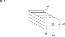
- FIG. 17 Another example of the acceleration detection element will be described with reference to FIGS. 17 and 18.
- FIG. 17 Another example of the acceleration detection element will be described with reference to FIGS. 17 and 18.
- FIG. 17 is a perspective view of an example of an acceleration detection element.
- FIG. 18 is a perspective view for explaining the internal structure of one example of the acceleration detection element.
- the acceleration detection element has a first clamping member 65, a second clamping member 66, a first exterior substrate 67, and a second exterior substrate 68.
- the acceleration sensing element has a piezoelectric element 64 .
- the piezoelectric element 64 has a rectangular parallelepiped shape.
- the piezoelectric element 64 has a first piezoelectric layer (not shown), a second piezoelectric layer, and detection electrodes.
- the first piezoelectric layer and the second piezoelectric layer are made of lead zirconate titanate-based ceramics. However, the materials of the first piezoelectric layer and the second piezoelectric layer are not limited to the above.
- the detection electrodes are provided on the outer surface of the first piezoelectric layer and the outer surface of the second piezoelectric layer, respectively.
- a first holding member 65 and a second holding member 66 are joined to the piezoelectric element 64 .
- the piezoelectric element 64 is a cantilever and is supported by a first clamping member 65 and a second clamping member 66 .
- the first holding member 65 and the second holding member 66 each have a groove that opens toward the piezoelectric element 64 .
- the groove forms a space that does not hinder displacement of the piezoelectric element 64 due to acceleration.
- the first exterior substrate 67 and the second exterior substrate 68 are made of an insulating material.
- the first exterior substrate 67 is a flat member.
- the second exterior substrate 68 has a recess.
- the recess forms a space that does not hinder displacement of the piezoelectric element 64 due to acceleration.
- the piezoelectric element 64 , the first clamping member 65 and the second clamping member 66 are arranged between the first exterior substrate 67 and the second exterior substrate 68 .
- the acceleration detection element may be an acceleration detection element having a capacitance element instead of a piezoelectric element.
- FIG. 19 shows an example in which the acceleration detection elements shown in FIGS. 17 and 18 are mounted on a substrate in a manner different from that shown in FIG. 1 and the like.
- FIG. 19 is a schematic perspective view for explaining the acceleration detection device according to the fifth embodiment of the invention.
- the acceleration detection element 63 is the acceleration detection element shown in FIGS.
- the acceleration detection element 63 is mounted near the outer periphery of the first main surface 2a of the substrate 2 . In this manner, the acceleration detection element 63 may be mounted on a portion other than the center of the substrate 2.
- FIG. A plurality of first circuit components 4 are also mounted on the first main surface 2a together with the acceleration detection element 63 .
- Acceleration detection element 63 is configured such that first holding member 65, first exterior substrate 67, and second exterior substrate 68 shown in FIG. It is mounted on the first main surface 2a. Therefore, the detection axis of the acceleration detection element 63 is perpendicular to the second surface 12 b of the second sealing portion 12 . That is, the detection axis is perpendicular to the mounting surface of the acceleration detection device 61 . For example, when the acceleration detection device 61 is mounted on a horizontal surface, the detection axis of the acceleration detection element 63 is vertical.
- a plurality of second circuit components 5 are mounted on the second main surface 2b of the substrate 2, as in the first embodiment shown in FIG. Then, as described above, the acceleration detection element 63 is mounted on the first main surface 2a. As a result, the area of the portion of the substrate 2 for providing the circuit components can be reduced, and the acceleration detection device 61 can be miniaturized.
- the main body is composed of the substrate 2, the acceleration detection element 63, the plurality of first circuit components 4, and the plurality of second circuit components.
- the acceleration detection element 63, the plurality of first circuit components 4, and the plurality of second circuit components are mounted on the substrate 2 so that the high-rigidity member 8 is located outside the center of gravity of the main body in plan view. It is As a result, as in the first embodiment, vibration in the acceleration detection device 61 can be suppressed, and high-frequency acceleration can be detected with high accuracy.
Abstract
L'invention concerne un dispositif de détection d'accélération qui peut présenter une taille réduite et qui peut détecter une accélération haute fréquence avec une précision élevée. La présente invention comprend : un substrat (2) doté de première et seconde surfaces principales (2a, 2b) ; un élément de détection d'accélération (3) monté sur la première surface principale (2a) ; des premier et second composants de circuit (4, 5) montés sur le substrat (2) ; un organe d'étanchéité (10) en résine comportant une première partie étanchéité (11) qui recouvre l'élément de détection d'accélération (3) disposé sur la première surface principale (2a), et une seconde partie étanchéité (12) qui recouvre le second composant de circuit (5) disposé sur la seconde surface principale (2b) et qui comprend des première et seconde surfaces (12a, 12b) ; et des organes à haute rigidité (8) qui s'étendent, à l'intérieur de la seconde partie étanchéité (12), dans une direction joignant la seconde surface (12b) et la seconde surface principale (2b) du substrat (2), et qui présentent une rigidité supérieure à celle de l'organe d'étanchéité (10). Dans une vue en plan, les organes à haute rigidité (8) sont positionnés davantage vers l'extérieur que le centre de gravité d'une section de corps (6) qui est constituée par le substrat (2), l'élément de détection d'accélération (3) et les premier et second composants de circuit (4, 5).
Applications Claiming Priority (2)
| Application Number | Priority Date | Filing Date | Title |
|---|---|---|---|
| JP2021-180490 | 2021-11-04 | ||
| JP2021180490 | 2021-11-04 |
Publications (1)
| Publication Number | Publication Date |
|---|---|
| WO2023079896A1 true WO2023079896A1 (fr) | 2023-05-11 |
Family
ID=86241304
Family Applications (1)
| Application Number | Title | Priority Date | Filing Date |
|---|---|---|---|
| PCT/JP2022/037390 WO2023079896A1 (fr) | 2021-11-04 | 2022-10-06 | Dispositif de détection d'accélération |
Country Status (1)
| Country | Link |
|---|---|
| WO (1) | WO2023079896A1 (fr) |
Citations (5)
| Publication number | Priority date | Publication date | Assignee | Title |
|---|---|---|---|---|
| JPH07128357A (ja) * | 1993-11-09 | 1995-05-19 | Murata Mfg Co Ltd | 加速度センサ |
| JP2006153724A (ja) * | 2004-11-30 | 2006-06-15 | Tateyama Kagaku Kogyo Kk | 加速度センサモジュール |
| CN205653159U (zh) * | 2016-05-16 | 2016-10-19 | 安徽北方芯动联科微系统技术有限公司 | 多轴mems传感器模块 |
| JP2017020829A (ja) * | 2015-07-08 | 2017-01-26 | セイコーエプソン株式会社 | センサーユニット、電子機器、および移動体 |
| JP2018072170A (ja) * | 2016-10-31 | 2018-05-10 | 日立オートモティブシステムズ株式会社 | 慣性力センサ装置 |
-
2022
- 2022-10-06 WO PCT/JP2022/037390 patent/WO2023079896A1/fr unknown
Patent Citations (5)
| Publication number | Priority date | Publication date | Assignee | Title |
|---|---|---|---|---|
| JPH07128357A (ja) * | 1993-11-09 | 1995-05-19 | Murata Mfg Co Ltd | 加速度センサ |
| JP2006153724A (ja) * | 2004-11-30 | 2006-06-15 | Tateyama Kagaku Kogyo Kk | 加速度センサモジュール |
| JP2017020829A (ja) * | 2015-07-08 | 2017-01-26 | セイコーエプソン株式会社 | センサーユニット、電子機器、および移動体 |
| CN205653159U (zh) * | 2016-05-16 | 2016-10-19 | 安徽北方芯动联科微系统技术有限公司 | 多轴mems传感器模块 |
| JP2018072170A (ja) * | 2016-10-31 | 2018-05-10 | 日立オートモティブシステムズ株式会社 | 慣性力センサ装置 |
Similar Documents
| Publication | Publication Date | Title |
|---|---|---|
| US6823747B2 (en) | Capacitive sensor | |
| EP1707920A2 (fr) | Capteur de vitesse angulaire | |
| JP4701505B2 (ja) | 慣性トランスデューサ | |
| US7650787B2 (en) | Acceleration sensor | |
| CN108291796B (zh) | 压电挠曲传感器以及检测装置 | |
| US10408619B2 (en) | Composite sensor | |
| US20170074653A1 (en) | Physical quantity sensor | |
| US6829953B2 (en) | Capacitive sensor | |
| US8166815B2 (en) | Angular velocity sensor element | |
| WO2023079896A1 (fr) | Dispositif de détection d'accélération | |
| US10508919B2 (en) | Composite sensor | |
| JP7003076B2 (ja) | センサ | |
| JP6255865B2 (ja) | センサーユニット、電子機器、および移動体 | |
| CN112448690B (zh) | 振动器件 | |
| CN113257746B (zh) | 振动器件 | |
| US20080257045A1 (en) | Sensor device for detecting physical quantity | |
| JP2006234463A (ja) | 慣性センサ | |
| US11874294B2 (en) | Acceleration detection device | |
| JPH0955638A (ja) | 圧電部品 | |
| KR20070027450A (ko) | 각속도 센서 | |
| JP2006234462A5 (fr) | ||
| US11114995B2 (en) | Piezoelectric component | |
| JP2006234462A (ja) | 慣性センサ | |
| JPH10170540A (ja) | 加速度センサ | |
| JPH07202283A (ja) | 圧電センサ及びその製造方法 |
Legal Events
| Date | Code | Title | Description |
|---|---|---|---|
| 121 | Ep: the epo has been informed by wipo that ep was designated in this application |
Ref document number: 22889720 Country of ref document: EP Kind code of ref document: A1 |
|
| ENP | Entry into the national phase |
Ref document number: 2023557907 Country of ref document: JP Kind code of ref document: A |