WO2023067882A1 - 可変速動力装置及び制御方法 - Google Patents
可変速動力装置及び制御方法 Download PDFInfo
- Publication number
- WO2023067882A1 WO2023067882A1 PCT/JP2022/031347 JP2022031347W WO2023067882A1 WO 2023067882 A1 WO2023067882 A1 WO 2023067882A1 JP 2022031347 W JP2022031347 W JP 2022031347W WO 2023067882 A1 WO2023067882 A1 WO 2023067882A1
- Authority
- WO
- WIPO (PCT)
- Prior art keywords
- rotor
- angle
- synchronous machine
- variable speed
- induced voltage
- Prior art date
Links
- 238000000034 method Methods 0.000 title claims description 15
- 230000001360 synchronised effect Effects 0.000 claims abstract description 140
- 238000004804 winding Methods 0.000 claims abstract description 33
- 230000004907 flux Effects 0.000 claims description 57
- 239000003638 chemical reducing agent Substances 0.000 claims description 14
- 238000013459 approach Methods 0.000 claims description 2
- 238000010586 diagram Methods 0.000 description 36
- 230000006870 function Effects 0.000 description 19
- 238000013016 damping Methods 0.000 description 15
- 230000000694 effects Effects 0.000 description 15
- 239000000696 magnetic material Substances 0.000 description 9
- 230000002093 peripheral effect Effects 0.000 description 8
- 238000012546 transfer Methods 0.000 description 7
- 238000012545 processing Methods 0.000 description 5
- 230000009467 reduction Effects 0.000 description 5
- 238000012360 testing method Methods 0.000 description 5
- 230000008859 change Effects 0.000 description 4
- 230000009471 action Effects 0.000 description 3
- 230000006698 induction Effects 0.000 description 3
- 230000004044 response Effects 0.000 description 3
- 238000004891 communication Methods 0.000 description 2
- 230000003247 decreasing effect Effects 0.000 description 2
- 230000001788 irregular Effects 0.000 description 2
- 238000012423 maintenance Methods 0.000 description 2
- 238000012986 modification Methods 0.000 description 2
- 230000004048 modification Effects 0.000 description 2
- 230000008569 process Effects 0.000 description 2
- 230000004043 responsiveness Effects 0.000 description 2
- 229910000831 Steel Inorganic materials 0.000 description 1
- 230000008901 benefit Effects 0.000 description 1
- 238000002474 experimental method Methods 0.000 description 1
- 230000006872 improvement Effects 0.000 description 1
- 230000002452 interceptive effect Effects 0.000 description 1
- 238000005259 measurement Methods 0.000 description 1
- 230000035699 permeability Effects 0.000 description 1
- 238000004549 pulsed laser deposition Methods 0.000 description 1
- 239000004065 semiconductor Substances 0.000 description 1
- 239000007787 solid Substances 0.000 description 1
- 239000010959 steel Substances 0.000 description 1
- 230000001052 transient effect Effects 0.000 description 1
Images


Classifications
-
- H—ELECTRICITY
- H02—GENERATION; CONVERSION OR DISTRIBUTION OF ELECTRIC POWER
- H02K—DYNAMO-ELECTRIC MACHINES
- H02K16/00—Machines with more than one rotor or stator
- H02K16/02—Machines with one stator and two or more rotors
-
- H—ELECTRICITY
- H02—GENERATION; CONVERSION OR DISTRIBUTION OF ELECTRIC POWER
- H02P—CONTROL OR REGULATION OF ELECTRIC MOTORS, ELECTRIC GENERATORS OR DYNAMO-ELECTRIC CONVERTERS; CONTROLLING TRANSFORMERS, REACTORS OR CHOKE COILS
- H02P23/00—Arrangements or methods for the control of AC motors characterised by a control method other than vector control
- H02P23/14—Estimation or adaptation of motor parameters, e.g. rotor time constant, flux, speed, current or voltage
-
- H—ELECTRICITY
- H02—GENERATION; CONVERSION OR DISTRIBUTION OF ELECTRIC POWER
- H02P—CONTROL OR REGULATION OF ELECTRIC MOTORS, ELECTRIC GENERATORS OR DYNAMO-ELECTRIC CONVERTERS; CONTROLLING TRANSFORMERS, REACTORS OR CHOKE COILS
- H02P25/00—Arrangements or methods for the control of AC motors characterised by the kind of AC motor or by structural details
- H02P25/02—Arrangements or methods for the control of AC motors characterised by the kind of AC motor or by structural details characterised by the kind of motor
- H02P25/022—Synchronous motors
- H02P25/024—Synchronous motors controlled by supply frequency
-
- H—ELECTRICITY
- H02—GENERATION; CONVERSION OR DISTRIBUTION OF ELECTRIC POWER
- H02P—CONTROL OR REGULATION OF ELECTRIC MOTORS, ELECTRIC GENERATORS OR DYNAMO-ELECTRIC CONVERTERS; CONTROLLING TRANSFORMERS, REACTORS OR CHOKE COILS
- H02P5/00—Arrangements specially adapted for regulating or controlling the speed or torque of two or more electric motors
- H02P5/46—Arrangements specially adapted for regulating or controlling the speed or torque of two or more electric motors for speed regulation of two or more dynamo-electric motors in relation to one another
Definitions
- the present disclosure relates to a variable speed power plant and control method.
- This application claims priority to Japanese Patent Application No. 2021-171614 filed in Japan on October 20, 2021, the content of which is incorporated herein.
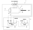
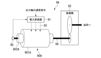
- FIG. 23 shows an example of a variable speed power plant 9A using a general synchronous machine 90A.
- the variable speed power plant 9A is composed of a synchronous machine 90A and a power converter 91 (inverter) for variable speed.
- the synchronous machine 90A has a stator 901A and a rotor 902A.
- a mechanical speed reducer 92 (gear) is generally used to drive a heavy object.
- the speed reducer 92 is connected to the output shaft 94 of the synchronous machine 90A, reduces the rotation speed of the synchronous machine 90A, and transmits it to the load.
- the speed reducer 92 transmits power by contacting gears, maintenance of the sliding portion is required.
- a synchronous machine with two rotors is called a magnetic geared motor.
- Magnetic geared motors use magnetic force to transmit power without contact between the rotors, which eliminates the need for maintenance of sliding parts. It has the advantage of being compact and lightweight.
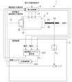
- FIG. 24 shows an example of a variable speed power plant 9B using a magnetic geared motor 90B.
- the variable speed power plant 9B is composed of a magnetic geared motor 90B and a power converter 91 .
- the magnetic geared motor 90B has a stator 901B, a first rotor 902B, and a second rotor 903B provided between the stator 901B and the first rotor 902B.
- First rotor 902B may be connected to other loads or power via output shaft 94A.
- the power that drives the synchronous machine 90A and the magnetic geared motor 90B is generally three-phase alternating current.
- the rotation speed of the general synchronous machine 90A synchronizes with the frequency of the driving power.
- the rotation speed of the synchronous machine 90A also changes in synchronism with it, and the speed of the load also changes. Therefore, if the relationship between the frequency of the electric power to be driven and the speed of the load is investigated in advance, the frequency can be adjusted to move the load at a desired speed.
- the magnetic geared motor 90B is also the same as the general synchronous machine 90A, and the speed of the load can be changed by adjusting the frequency of the electric power to be driven.
- step-out may occur when the load is excessive.
- the synchronous machine 90A has an upper limit to the torque it can output.
- the rotation speed of the synchronous machine 90A is independent of the frequency of the electric power to be driven, so the load cannot be moved at a desired speed. Not only that, but if it loses synchronism, the machine that acts as a load will generate a large amount of vibration and noise, and there is a possibility that the machine will break down. Therefore, it is important not to let the synchronous machine 90A and the magnetic geared motor 90B run out of step.
- the driving power voltage is synchronized with the electrical angle of the induced voltage generated in the armature (armature winding of the stator 901A) due to the rotation of the magnetic poles of the rotor 902A.
- the phase of the voltage of the power line 93 is adjusted so that the difference between the electrical angle of the induced voltage and the voltage angle of the drive power, that is, the electrical angle does not exceed ⁇ 90 degrees.
- the phase or frequency of the power output by the power converter 91 reflects the rotation angle or rotation speed of the rotor 902A. By lowering it, it becomes possible to prevent loss of synchronism.
- the induced voltage is the time derivative of the magnetic flux interlinking the armature. Since the interlinkage magnetic flux rotates together with the rotor 902A, if the angle of the rotor 902A is known, the interlinkage magnetic flux and the induced voltage obtained by differentiating it can also be known. Since the general synchronous machine 90A has one rotor 902A, it is sufficient for the induced voltage generated in the armature to know the angle of one rotor 902A. Since the rotor 902A is connected to the output shaft 94, the rotation angle sensor 95 provided on the output shaft 94 can measure the angle of the output shaft 94, that is, the angle of the rotor 902A.
- Patent Literature 1 describes a technique of measuring the angle of an output shaft with a rotation angle sensor and commutating AC power to drive in synchronization with the rotation of the output shaft. By doing so, the frequency of the power flowing through the power line is synchronized with the output shaft.
- the magnetic geared motor 90B has a second rotor 903B in addition to the first rotor 902B corresponding to the rotor 902A of the synchronous machine 90A.
- Patent Document 1 describes a magnetic geared motor having a first rotor (first rotor) and a second rotor (second rotor), in which power is output from the second rotor. is further described. That is, in the magnetic geared motor disclosed in Patent Document 1, the rotation angle sensor that measures the angle of the output shaft measures the angle of the second rotor.
- the induced voltage generated in the armature depends not only on the angle of the second rotor but also on the angle of the first rotor. Therefore, in the technique described in Patent Document 1, an error may occur due to ignoring the influence of the first rotor. Then, in a situation in which the induced voltage is determined by the angle of the first rotor rather than the angle of the second rotor, step-out may occur.
- the present disclosure has been made in view of such problems, and provides a variable speed power plant and a control method capable of suppressing step-out of a synchronous machine.
- a variable speed power plant includes a stator provided with an armature winding to form an armature, a first rotor having magnetic poles, the first rotor and the a second rotor provided between a stator and driving a load; a synchronous machine having a first angle of the first rotor and a second angle of the second rotor; an induced voltage angle estimating unit for estimating the electrical angle of the induced voltage generated in the armature based on the estimated electrical angle of the induced voltage; a converter;
- a variable speed power plant includes a stator provided with an armature winding to form an armature, a first rotor having magnetic poles, the first rotor and the a second rotor provided between a stator; and a voltage for driving the synchronous machine among the electrical angle of the first rotor and the electrical angle of the second rotor. and a power converter that performs V/f control based on the larger absolute value of the offset from the electrical angle of and adjusts the frequency of the power that drives the synchronous machine.
- a stator provided with armature windings to form an armature, a first rotor having magnetic poles, and between the first rotor and the stator: a second rotor provided to drive a load, a control method for a synchronous machine comprising: based on a first angle of the first rotor and a second angle of the second rotor, estimating an electrical angle of the induced voltage generated in the armature; and adjusting a frequency of power for driving the synchronous machine based on the estimated electrical angle of the induced voltage.
- variable speed power plant and control method it is possible to suppress step-out of the synchronous machine.
- FIG. 1 is a diagram showing a functional configuration of a variable speed power plant according to a first embodiment of the present disclosure
- FIG. 1 is a cross-sectional view of a synchronous machine according to a first embodiment of the present disclosure
- FIG. FIG. 3 is a diagram for explaining the concept of operation of the power converter according to the first embodiment of the present disclosure
- FIG. FIG. 6 is a diagram showing a functional configuration of a variable speed power plant according to a second embodiment of the present disclosure
- FIG. FIG. 5 is a cross-sectional view of a first rotor according to a third embodiment of the present disclosure
- FIG. 11 is a cross-sectional view of a first rotor according to a fourth embodiment of the present disclosure
- FIG. 11 is a perspective view of a first rotor according to a fourth embodiment of the present disclosure
- FIG. 11 is a diagram showing a functional configuration of a variable speed power plant according to a fifth embodiment of the present disclosure
- FIG. 12 is a diagram showing a functional configuration of a variable speed power plant according to a sixth embodiment of the present disclosure
- FIG. 11 is a diagram showing a functional configuration of a variable speed power plant according to a seventh embodiment of the present disclosure
- FIG. 13 is a diagram showing a functional configuration of a variable speed power plant according to an eighth embodiment of the present disclosure
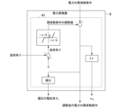
- FIG. 21 is a diagram showing a functional configuration of a power converter according to an eighth embodiment of the present disclosure
- FIG. 20 is a diagram showing a functional configuration of a variable speed power plant according to a ninth embodiment of the present disclosure; It is a figure which shows the functional structure of the power converter which concerns on 9th Embodiment.
- FIG. 22 is a diagram showing an example of an induced voltage vector according to the ninth embodiment of the present disclosure;
- FIG. 20 is a diagram showing a functional configuration of a variable speed power plant according to a tenth embodiment of the present disclosure;
- FIG. 22 is a diagram for explaining the operation of the power converter according to the tenth embodiment of the present disclosure;
- FIG. FIG. 22 is a diagram showing an example of load angles according to the tenth embodiment of the present disclosure;
- FIG. 20 is a diagram showing a functional configuration of a variable speed power plant according to an eleventh embodiment of the present disclosure
- FIG. 20 is a diagram showing a functional configuration of a variable speed power plant according to a twelfth embodiment of the present disclosure
- FIG. 22 is a diagram illustrating a functional configuration of a power converter according to a twelfth embodiment of the present disclosure
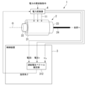
- FIG. 1 is a diagram showing an example of a hardware configuration of equipment that constitutes a variable speed power plant according to at least one embodiment of the present disclosure
- FIG. 1 is a first diagram showing an example of a conventional variable speed power plant
- FIG. FIG. 2 is a second diagram showing an example of a conventional variable speed power plant;
- variable speed power plant 1 according to a first embodiment of the present disclosure will be described below with reference to the drawings.
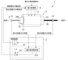
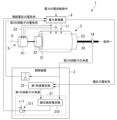
- FIG. 1 is a diagram showing the functional configuration of a variable speed power plant according to the first embodiment of the present disclosure. As shown in FIG. 1 , the variable speed power plant 1 includes a synchronous machine 2 , a control device 3 and a power converter 4 .
- the synchronous machine 2 is a magnetic geared motor.
- a magnetic geared motor also serves as a magnetic geared generator. Therefore, the synchronous machine 2 according to this embodiment serves as both a motor and a generator.
- the example which uses the synchronous machine 2 as a motor is demonstrated.
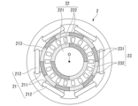
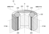
- FIG. 2 is a cross-sectional view of a synchronous machine according to the first embodiment of the present disclosure. As shown in FIGS. 1 and 2, the synchronous machine 2 has a stator 21, a first rotor 22, a second rotor 23, an output shaft 24, and an output shaft 24A.
- the stator 21 is an annular structure surrounding the first rotor 22 and the second rotor 23 .
- the stator 21 forms an armature in which an armature winding 212 is provided on each of a plurality of teeth 211 protruding radially inward.
- the first rotor 22 is a rotor that rotates around the rotation axis O.
- the first rotor 22 has a core 221 made of soft magnetic material and a plurality of magnetic poles 222 .
- Magnetic pole 222 is, for example, a permanent magnet.
- the number of magnetic poles of the first rotor 22 is four in the example of FIG. 2, it is not limited to this. In other embodiments, the number of magnetic poles of the first rotor 22 may vary.
- First rotor 22 is connected to other loads or power through output shaft 24A.
- the configuration is not limited to this.
- the first rotor 22 may have a configuration in which a plurality of magnetic poles (salient poles) projecting radially outward from the outer peripheral surface are integrally formed with the core 221 .
- the first rotor 22 may not be provided with magnets or electromagnets.
- the core 221 of the first rotor 22 may be made of a soft magnetic material such as a magnetic steel plate, and magnets may be arranged on the outer peripheral surface of the core 221 at intervals. That is, instead of covering the entire outer peripheral surface of the core 221 with magnets as in the example of FIG. 2, the soft magnetic material may be exposed between adjacent magnets (boundaries).
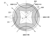
- the second rotor 23 is provided between the stator 21 and the first rotor 22.
- the second rotor 23 is an annular structure that surrounds the first rotor 22 and rotates around the rotation axis O. As shown in FIG. As shown in FIG. 1, the second rotor 23 is coupled to the output shaft 24 and drives a load connected to the output shaft 24 .
- the second rotor 23 has magnetic poles 231 and non-magnetic portions 232 alternately arranged in the circumferential direction.
- the magnetic pole 231 is made of magnetic material (soft magnetic material or hard magnetic material).
- the non-magnetic portion 232 is made of a non-magnetic material.
- the non-magnetic portion 232 may be a gap formed by radially cutting a magnetic material.
- the control device 3 is a device for controlling the operation of the synchronous machine 2.
- the control device 3 according to this embodiment has an induced voltage angle estimator 31 .
- the induced voltage angle estimator 31 has a magnetic flux linkage estimator 310 and a calculator 311 .
- the interlinkage magnetic flux estimator 310 determines the magnetic flux interlinking with the armature winding 212 based on the angle of the first rotor 22 (first angle) and the angle of the second rotor 23 (second angle). Estimate the angle of Note that the magnetic flux linkage estimator 310 according to the present embodiment acquires the angle of the first rotor 22 from the first angle sensor 13 provided on the first rotor 22, and outputs the angle to the second rotor 23. The angle of the second rotor 23 is acquired from the provided second angle sensor 14 .
- the calculation unit 311 calculates the electrical angle of the armature induced voltage based on the estimated magnetic flux angle.
- the calculated electrical angle of the induced voltage is output to the power converter 4 .
- the power converter 4 is electrically connected to the synchronous machine 2 via the power line 11 (the armature winding 212 of the synchronous machine 2).
- the power converter 4 converts power to drive the synchronous machine 2 using techniques such as V/f control and vector control based on the power frequency command value and the electrical angle of the induced voltage input from the control device 3. Adjust the frequency, voltage and current of the
- the magnetic poles 231 and the non-magnetic portions 232 are alternately arranged in the circumferential direction of the second rotor 23, the ease of passage of the magnetic flux of the second rotor 23, that is, the permeance of the second rotor 23 angle, in other words, the circumferential position on the second rotor 23 .
- the angle of the second rotor is based on the circumferential direction in which the permeance is maximum
- the permeance at a position advanced by an angle ⁇ on the second rotor from the reference direction of the second rotor is expressed by the following equation ( 3) can be approximated.
- p 2 is the number of poles of the second rotor 23 .
- the electrical angle is the value obtained by multiplying the rotor angle (mechanical angle) by the number of poles.
- the permeance repeats the cycle of increasing and decreasing p 2 times.
- B 20 ⁇ B 21 >0. This expresses the physical constraint that the permeance is always positive.
- the magnetic flux interlinking with the armature in the direction ⁇ advanced from the reference point of the stator 21 is given by the following equation: expressed.
- ⁇ 1 , ⁇ 2 are based on prior information that "the angle of the first rotor 22 is ⁇ 1 and the angle of the second rotor 23 is ⁇ 2 ". means the magnetic flux ⁇ at the angle ⁇ .
- Equation (5) may be solved by numerical search or numerical solution so that the partial differential with respect to the interlinking ⁇ becomes zero.
- the synchronous machine 2 of the type in which the magnets 213 are not provided between the second rotor 23 and the teeth 211 of the stator 21 has been described as an example.
- a similar calculation can be made for the synchronous machine 2 of the type in which the magnet 213 is provided.
- the magnetic flux linkage estimator 310 calculated the direction of the magnetic flux from constants such as A1, B20, and B21. Not limited to this, the maximum direction can also be obtained by numerical analysis or experiment. For example, a table for estimating the magnetic flux linkage of the armature from the angle of the first rotor 22 and the angle of the second rotor 23 may be prepared in advance. In this case, the magnetic flux linkage estimator 310 measures the angle ⁇ 1 of the first rotor 22 and the angle ⁇ 2 of the second rotor 23, and calculates the angle of the magnetic flux linkage from the prepared table. .
- the electrical angle of the induced voltage (generally, the interlinking magnetic flux is advanced by ⁇ /2 in electrical angle) can be found.
- the calculator 311 calculates the electrical angle of the induced voltage based on the angle of the magnetic flux linkage estimated by the magnetic flux linkage estimator 310 .
- the calculated electrical angle of the induced voltage is output to the power converter 4 .
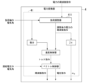
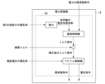
- FIG. 3 is a diagram for explaining the concept of operation of the power converter according to the first embodiment of the present disclosure.
- the output shaft is connected to the second rotor.
- the power converter 4 is an example of controlling the synchronous machine 2 by vector control based on the electrical angle of the induced voltage.
- Vector control generally adjusts the output torque of the synchronous machine 2 .
- the command value of the output torque is output by a speed controller arranged above the vector control.
- the speed controller inputs a frequency command of electric power representing a speed command and an electrical angular frequency of a load shaft, and outputs a torque command by, for example, proportional integral control calculation.
- the second rotor 23 corresponds to the load shaft.
- the vector controller outputs a voltage command and a frequency command based on the electrical angle of the induced voltage and the electric current output by the power converter 4 .
- the power converter 4 supplies power to the armature according to the voltage command and frequency command.
- the induced voltage generated in the armature from the angle of the first rotor 22 and the angle of the second rotor 23 of the synchronous machine 2 An induced voltage angle estimator 31 for estimating an angle, and a power converter 4 for adjusting the frequency of power for driving the synchronous machine 2 based on the estimated electrical angle of the induced voltage. Further, the induced voltage angle estimator 31 according to the present embodiment estimates the angle of magnetic flux interlinking with the armature winding 212 based on the angle of the first rotor 22 and the angle of the second rotor 23. It has a magnetic flux linkage estimator 310 and a calculator 311 that calculates the electrical angle of the induced voltage based on the angle of the magnetic flux linkage and the angle of the second rotor 23 .
- Adopting vector control for the power converter 4 improves the responsiveness of the mechanical output of the synchronous machine 2 compared to adopting the V/f control.
- Vector control requires the electrical angle of the induced voltage.
- the electrical angle of the induced voltage was unknown, and it was not possible to obtain the quick response inherent in vector control.
- the first rotor may vibrate and step out.
- vector control is performed using the electrical angle of the induced voltage estimated based on the angle of the first rotor and the angle of the second rotor. The effect of improving responsiveness or preventing step-out can be obtained.
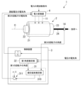
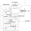
- FIG. 4 is a diagram showing the functional configuration of a variable speed power plant according to a second embodiment of the present disclosure.
- the control device 3 according to this embodiment further has a first angle estimator 32 .
- the first angle estimator 32 uses adjustment constants ⁇ 1 and ⁇ 2 determined in advance by testing or analysis to obtain the angle (second angle) of the second rotor 23 measured by the second angle sensor 14. and the electrical angle ⁇ V of the voltage, the angle (first angle) of the first rotor 22 is estimated.
- control device 3 (Operation of control device) Next, the operation of the control device 3 according to this embodiment will be described in detail. Instead of the first angle sensor 13 of the first rotor 22, the control device 3 according to the present embodiment detects the first rotor angle from the angle of the second rotor 23 and the voltage and current of the three-phase alternating current. A first angle estimator 32 that estimates the angle of 22 is used.
- Parameters n 12 , J, C, and K of the transfer function are values specific to the synchronous machine 2 and can be determined by preliminary tests or the like.
- the first angle estimator 32 calculates this transfer function. If it is found in a preliminary test that the values of the parameters such as K of the transfer function change greatly depending on the output torque of the synchronous machine, the values of K and the like may be changed according to the operation of the synchronous machine.
- the operations of the magnetic flux linkage estimation unit 310 and the calculation unit 311 are the same as in the first embodiment.
- variable speed power plant 1 further includes the first angle estimator 32 that estimates the angle of the first rotor 22 based on the angle of the second rotor 23 .
- the first angle sensor 13 for measuring the angle of the first rotor 22 and its wiring can be eliminated. As a result, it is possible to realize compactness and cost reduction of the variable speed power plant 1 .
- variable speed power plant 1 according to a third embodiment of the present disclosure will be described.
- the output shaft is connected to the second rotor.
- the same reference numerals are given to the same components as in the above-described embodiment, and detailed description thereof will be omitted.
- FIG. 5 is a cross-sectional view of a first rotor according to a third embodiment of the present disclosure.
- the first rotor 22 according to this embodiment has hollowed portions 223 formed around the rotation axis O.
- the lightening portion 223 is formed by lightening the core 221 of the first rotor 22 .
- the first angle estimator 32 estimates the angle of the first rotor 22 instead of the first angle sensor 13 of the first rotor 22 . That is, the angle of the first rotor 22 is an estimated value instead of an actual value.
- the estimated value of the angle of the first rotor 22 is calculated by a motion equation consisting of the inertia rate of the first rotor 22 and the electromagnetic torque acting on the first rotor 22 .
- the accuracy of the estimated value of the angle of the first rotor 22 improves as the natural frequency ⁇ n determined from the characteristic root of the equation of motion increases and as the damping ratio ⁇ increases. These can be achieved by lowering the inertia rate of the second rotor 23 .
- the characteristic root is "-C ⁇ (C 2 -4KJ)/2J”.
- the natural angular frequency ⁇ n is " ⁇ (K/J)”
- the damping ratio ⁇ is "C/2 ⁇ (KJ)”.
- the inertia ratio J is large, so the natural angular frequency ⁇ n is small, the damping ratio ⁇ is small, and the accuracy of estimating the angle of the first rotor 22 may deteriorate.
- the inertia ratio J of the first rotor 22 is lowered to increase both the natural angular frequency and the damping ratio, and the transfer function (equation 7) described in the second embodiment is changed to the following equation (8 ) to reduce the angle estimation error in the first angle estimator 32 by using a first-order lag response with effective attenuation.
- the core 221 (soft magnetic material) of the first rotor 22 is formed with hollowed portions 223 to reduce the inertia rate of the first rotor 22 .
- the number of lightening portions 223 is large at the center of the circumferential expansion of the magnetic pole 222 (the center of the magnetic pole 222) and small between the adjacent magnetic poles (between the magnetic poles). That is, the radial length (the length from the rotation axis O) of the lightening portion 223 is set to be longer toward the center of the magnetic pole 222 and shorter toward the middle of the two adjacent magnetic poles 222. .
- the first rotor 22 is independent of external loads.
- the rotor of a synchronous machine balances at an angle that maximizes the magnetic flux when there is no load.
- the main component of the magnetic flux is in the radial direction at the center of the magnetic pole, and the component in the circumferential direction is small. Therefore, even if the center of the magnetic pole is deeply recessed, the magnetic flux is not disturbed.
- the thickness of the recessed portion 223 is increased at the center of the magnetic pole 222 and decreased at the middle of the magnetic pole. Specifically, as shown in FIG. When it is measured, the following equation (9) holds.
- E(d( ⁇ m )) is the average value of d.
- d is calculated for each lightening hole, and the total value is E(d( ⁇ m )).
- the first rotor 22 has the recessed portion 223 around the rotation axis O. As shown in FIG.
- the angle of the first rotor 22 can be accurately estimated in this way, so the processing of the magnetic flux linkage estimator 310 may be simplified. Specifically, the magnetic flux linkage estimator 310 approximates the electrical angle of the first rotor 22 by the weighted sum of the electrical angle of the second rotor 23 and the electrical angle of the voltage, and calculates the angle of the magnetic flux linkage can be estimated.
- the radial length of the lightening portion 223 is set so as to increase toward the center of the magnetic pole 222 .
- the recessed portion 223 can be formed without interfering with the magnetic flux.
- variable speed power plant 1 a variable speed power plant 1 according to a fourth embodiment of the present disclosure will be described.
- the output shaft is connected to the second rotor.
- the same reference numerals are given to the same components as in the above-described embodiment, and detailed description thereof will be omitted.
- FIG. 6 is a cross-sectional view of a first rotor according to a fourth embodiment of the present disclosure
- FIG. 7 is a perspective view of a first rotor according to a fourth embodiment of the present disclosure
- the first rotor 22 according to the present embodiment has damper windings 224 wound so as to be interlinked with the magnetic flux passing through the meridional plane including the centers of the magnetic poles 222. have more.
- FIG. 7 is an image of a portion of the first rotor 22 cut along the meridional plane in the circumferential direction.
- the damper winding 224 is wound around the deepest recessed portion of the recessed portion 223 (the inner peripheral surface of the core 221 ) and the radially outer peripheral surface of the core 221 .
- J is reduced by lightening as in the third embodiment, so the transfer function is approximated by the coefficient n12 as shown in the following equation (11). That is, since the first rotor 22 can follow the angle of the second rotor 23 without delay, step-out can be suppressed more reliably.
- the first rotor 22 includes the damper winding 224 wound so as to interlink with the magnetic flux passing through the meridional plane including the center of the magnetic pole 222. further has
- variable speed power plant 1 is more difficult to step out than in the third embodiment.
- variable speed power plant 1 a variable speed power plant 1 according to a fifth embodiment of the present disclosure will be described.
- the output shaft is connected to the second rotor.
- the same reference numerals are given to the same components as in the above-described embodiment, and detailed description thereof will be omitted.
- FIG. 8 is a diagram showing the functional configuration of a variable speed power plant according to the fifth embodiment of the present disclosure.
- the variable speed power plant 1 according to this embodiment further includes a first electric motor 5 in addition to the configuration according to the second embodiment.
- the first electric motor 5 has a rotor 51 (third rotor) and electric wires 52 .
- the first electric motor 5 is, for example, an induction motor.
- the first electric motor 5 is configured to have the same synchronous speed as the synchronous machine 2 or the same number of poles as the synchronous machine 2 .
- the rotor 51 of the first electric motor 5 is mechanically connected to the first rotor 22 of the synchronous machine 2 .
- the electric wire 52 is electrically connected in parallel with the armature winding 212 of the synchronous machine 2 .
- the lightening portion 223 and the damper winding 224 of the first rotor 22 improve the motion damping ratio of the first rotor 22 .
- the first rotor 22 since the first rotor 22 is located inside the synchronous machine 2, there may be a case where only the lightening part 223 and the damper winding 224 cannot sufficiently improve the situation due to space restrictions.
- the functions of the lightening portion 223 and the damper winding 224 according to the third and fourth embodiments are replaced with the first electric motor 5 arranged outside.
- the first electric motor 5 is connected to the power converter 4 and consumes part of the three-phase AC power that the power converter 4 supplies to the synchronous machine 2 .
- the first electric motor generates a damping force proportional to the difference between the synchronous speed of the first electric motor 5 determined by the frequency of the electric power and the rotational speed of the first electric motor 5 due to the nature of the induction motor. Since the first electric motor 5 is connected to the first rotor 22, the generated damping force also acts on the first rotor as a damping force. Therefore, the same effect as increasing the damping coefficient C of the first rotor can be obtained.
- variable speed power plant 1 has the same number of poles as the first rotor 22 of the synchronous machine 2, and is mechanically connected to the first rotor 22. 51 (third rotor) and an electric line 52 electrically connected in parallel with the armature winding 212 of the synchronous machine 2 is further provided.
- variable speed power plant 1 can follow a more rapid load change, and can widen the range in which step-out can be avoided. That is, step-out can be suppressed more strongly.
- variable speed power plant 1 according to a sixth embodiment of the present disclosure will be described.
- the output shaft is connected to the second rotor.
- the same reference numerals are given to the same components as in the above-described embodiment, and detailed description thereof will be omitted.
- FIG. 9 is a diagram showing the functional configuration of a variable speed power plant according to the sixth embodiment of the present disclosure. As shown in FIG. 9, the variable speed power plant 1 according to this embodiment further includes a speed reducer 6 in addition to the configuration according to the second embodiment.
- the speed reducer 6 has a joint 63 that connects the first rotor 22 and the second rotor 23 of the synchronous machine 2 .
- Joint 63 is an elastic joint or a viscous joint.
- the speed reducer 6 also has a first gear 61 and a second gear 62 .
- the first gear 61 is connected with the output shaft 24 of the synchronous machine 2 . Therefore, the first gear 61 rotates at the same speed as the second rotor 23 .
- the second gear 62 further transmits the power of the second rotor 23 of the synchronous machine 2 transmitted from the first gear 61 to the joint 63 .
- Joint 63 is connected to first rotor 22 via shaft 64 . Thereby, the angle of the first rotor 22 follows the angle of the second rotor 23 .
- the speed reducer 6 is made equal to the speed ratio of the first rotor and the second rotor, the speed reducer is normally operated without load. Only when a speed difference occurs transiently between the two, a damping force corresponding to the speed difference is generated due to the action of the viscoelastic joint. This has the same effect as increasing the damping coefficient C of the first rotor 22 . Thereby, it is possible to suppress the first rotor 22 from vibrating with respect to the second rotor 23 . Thereby, the accuracy of estimating the angle of the first rotor 22 in the first angle estimator 32 can be improved.
- each configuration of the speed reducer 6 (the first gear 61, the second gear 62, the joint 63, and the shaft 64 connecting the joint 63 and the first rotor 22) is shown.
- An example of external placement is shown, but the present invention is not limited to this.
- the speed reducer 6 may be configured by, for example, a planetary gear and arranged inside the synchronous machine 2 .
- variable speed power plant 1 further includes the reduction gear 6 connected to the synchronous machine.
- the speed reducer 6 has a joint 63 that connects the first rotor 22 and the second rotor of the synchronous machine 2 .
- variable speed power plant 1 can suppress irregular vibration of the first rotor 22 of the synchronous machine 2 with respect to the second rotor 23 . Thereby, the accuracy of estimating the angle of the first rotor 22 in the first angle estimator 32 can be improved.
- variable speed power plant 1 according to a seventh embodiment of the present disclosure will be described.
- the output shaft is connected to the second rotor.
- the same reference numerals are given to the same components as in the above-described embodiment, and detailed description thereof will be omitted.
- FIG. 10 is a diagram showing the functional configuration of a variable speed power plant according to the seventh embodiment of the present disclosure. As shown in FIG. 10, the variable speed power plant 1 according to this embodiment further includes a second electric motor 7 and a second power converter 8 in addition to the configuration according to the second embodiment.
- the second electric motor 7 has a rotor 71 (fourth rotor).
- the rotor 71 is mechanically connected with the first rotor 22 of the synchronous machine 2 .
- the second electric motor 7 is, for example, a small induction motor or a small synchronous motor.
- the second power converter 8 adjusts the frequency of the electric power that drives the second electric motor 7 so that the rotation speed of the second rotor 23 matches the rotation speed of the first rotor of the synchronous machine 2 . Electric power is supplied to the second electric motor 7 . Additionally, the second power converter 8 may supply power to the second electric motor 7 to assist the synchronous machine 2 .
- the second electric motor 7 is connected to the first rotor 22 of the synchronous machine 2 .
- the second electric motor 7 is powered by a second power converter 8 .
- the second power converter 8 multiplies the rotation speed [rps] of the second rotor 23 obtained from the time differential value of the angle of the second rotor 23 of the synchronous machine 2 by p 1 n 12 /2 to obtain the
- the target frequency of the second power converter 8 is generated so that the rotation speed of the second rotor 23 becomes the synchronous rotation speed of the first rotor 22 .
- the second power converter 8 adjusts the frequency and phase of electric power for driving the second electric motor 7 so that the rotation speed of the first rotor 22 matches the synchronous rotation speed. Further, the second power converter 8 may additionally advance the voltage of the power that drives the power to the second motor 7 to assist the synchronous machine 2 .
- the variable speed power plant 1 includes the second electric motor 7 mechanically connected to the first rotor 22 of the synchronous machine 2 and the second rotor 23 of the synchronous machine 2. and a second power converter 8 for adjusting the frequency of the power driving the second electric motor 7 to match the speed of the motor.
- the power supplied by the second power converter 8 to the second electric motor 7 acts as a damping force when the second electric motor 7 and the first rotor 22 move relative to the second rotor 23, This relative motion is restricted.
- the load driving capability is improved.
- variable speed power plant 1 can suppress irregular vibration of the first rotor 22 of the synchronous machine 2 with respect to the second rotor 23 .
- the accuracy of estimating the angle of the first rotor 22 in the first angle estimator 32 can be improved.
- the variable speed power plant 1 can follow a more rapid load change, and can widen the range in which step-out can be avoided. That is, step-out can be suppressed more strongly.
- variable speed power plant 1 according to an eighth embodiment of the present disclosure will be described.
- the same reference numerals are given to the same components as in the above-described embodiment, and detailed description thereof will be omitted.
- FIG. 11 is a diagram showing a functional configuration of a variable speed power plant according to an eighth embodiment of the present disclosure.
- the variable speed power plant 1 does not have the magnetic flux linkage estimator 310 .
- Magnetic flux linkage estimator 310 performed vector control in power converter 4 based on the electrical angle of the voltage induced by first rotor 22 and second rotor 23 .
- the power converter 4 uses V/f control instead of vector control, thereby eliminating the need to estimate the electrical angle of the induced voltage. It is known that the rotational speed of the synchronous machine follows the synchronous speed of the frequency of the drive power with a time delay and finally settles at the synchronous speed. Since the magnetic geared motor of the present application also belongs to the synchronous machine, it has this property.
- the rotation of the magnetic geared motor follows the synchronous speed determined by the frequency of the drive power, albeit with a delay. can be achieved.
- the rotation follow-up delay becomes excessive, stepping out occurs, and the original function of the synchronous machine is lost.
- Step-out occurs when the offset between the electrical angle of the drive power voltage and the electrical angle of the rotor exceeds ⁇ 90°. Therefore, the offsets of the respective rotors are compared, and the voltage of the drive power is adjusted so that the offset of the rotor having the larger offset does not exceed ⁇ 90°, thereby avoiding step-out.
- the first angle sensor 13 measures the angle of the first rotor 22 .
- the induced voltage angle estimator 31 obtains the electrical angle of the first rotor by dividing the value measured by the first angle sensor 13 by 1/2 of the pole number p1 of the first rotor.
- the induced voltage angle estimator 31 obtains the electrical angle of the second rotor by dividing the value measured by the second angle sensor 14 by the number of poles p2 of the second rotor.
- the power converter 4 inputs the electrical angle of the induced voltage of the first rotor 22 and the electrical angle of the induced voltage of the second rotor 23, and calculates offset 1 and offset 2 with respect to the electrical angle of the voltage, respectively. do. Offset 1 and offset 2 are compared, and the value with the larger absolute value is determined as the final offset . Avoid tones. For example, as shown in FIG. 12, this adjustment is performed by the load adjuster 411 of the arithmetic function unit 41 inside the power converter 4, where the final offset is within a predetermined allowable range (for example, [-30°, +30°]). range), the adjusted value of the frequency command is zero. When the final offset exceeds the allowable range, it is adjusted by adding a value proportional to the final offset as an adjustment value to the frequency command so that the absolute value of the final offset becomes small.
- a predetermined allowable range for example, [-30°, +30°]
- the power voltage command is determined, for example, from a preset function based on the power frequency command.
- the electric power converter 4 has the electric angle of the voltage and the electric angle of the first rotor 22 and the electric angle of the second rotor 23 .
- V/f control is performed based on the larger absolute value of the offset of , and the frequency of the electric power for driving the synchronous machine 2 is adjusted.
- variable speed power plant 1 does not need to estimate the angle of the combined magnetic flux by the first rotor and the second rotor, unlike the vector control described in the first embodiment, for example. Therefore, the processing of the flux linkage estimator 310 can be omitted. In applications where a gentle response is required, adopting the variable speed power plant 1 according to the present embodiment makes it possible to suppress step-out with simpler processing.
- a feature of the present embodiment is that, of the first rotor 22 and the second rotor 23, the drive power, particularly the frequency, is adjusted based on the electrical angle of the induced voltage of the rotor closer to out-of-step. be.
- a vector controller based on the electrical angle of the induced voltage of the first rotor 22 and a vector controller based on the electrical angle of the induced voltage of the second rotor 23 are provided.
- vector control may be performed using the vector controller of the rotor closer to step-out.
- variable speed power plant 1 according to a ninth embodiment of the present disclosure will be described.
- the same reference numerals are given to the same components as in the above-described embodiment, and detailed description thereof will be omitted.
- FIG. 13 is a diagram showing the functional configuration of a variable speed power plant according to the ninth embodiment of the present disclosure. As shown in FIG. 13 , the control device 3 according to this embodiment has an induced voltage vector estimator 312 .
- the induced voltage vector estimation unit 312 estimates the angle of the induced voltage vector based on the voltage and current of the power line 11 that drives the synchronous machine 2, and outputs the electrical angle of the induced voltage. The calculated electrical angle of the induced voltage is output to the power converter 4 .
- FIG. 14 is a diagram showing the functional configuration of a power converter according to the ninth embodiment.
- the power converter 4 according to the present embodiment has a load adjuster 411 in addition to the vector controller in the arithmetic function unit 41 .
- a specific configuration of the load adjuster 411 is similar to that of the eighth embodiment.
- the arithmetic function unit 41 calculates the electrical angle ⁇ V of the voltage and the angle ( The frequency of the power is adjusted based on the offset of the second angle) to prevent load axis step-out.
- the induced voltage vector estimator 312 estimates the induced voltage vector generated in the armature from the voltage vector, the current vector, and the impedance of the armature.
- a current vector and a voltage vector are calculated from the electrical angle ⁇ e of the second rotor by equations (12) and (13), respectively.
- i is the AC phase current supplied to the synchronous machine 2
- v is the AC phase voltage supplied to the synchronous machine 2.
- the symbol " ⁇ " indicates a complex number.
- j is the imaginary unit.
- the synchronous machine 2 is generally driven by three-phase alternating current.
- the voltage vector and current vector are calculated by equations (14) and (15), respectively.
- the three phases are U phase, V phase, and W phase, and the electrical angles of the V phase and W phase are 120° (2 ⁇ /3) and 240° (4 ⁇ /3) is subtracted.
- the scope of the present embodiment also includes consideration of such a phase difference.
- the induced voltage vector E ⁇ * is composed of the voltage vector V ⁇ and the current vector I ⁇ ⁇ can be calculated by the following equation (18).
- the impedance is calculated from the resistance R and the inductance L by the following equation (19).
- the values of R and L are predetermined.
- ⁇ e is, for example, the angular frequency of the adjusted frequency command.
- the electrical angular frequency of the first rotor 22, the electrical angular frequency of the second rotor 23, and the electrical angular frequency of the induced voltage may be used as ⁇ e .
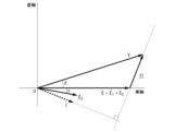
- FIG. 15 is a diagram showing an example of an induced voltage vector according to the eighth embodiment of the present disclosure, representing a load operating state.
- FIG. 15 shows how the angle of the induced voltage vector is offset with respect to the electrical angle of the second rotor 23 due to the influence of the first rotor 22 .
- FIG. 15 shows that the electrical angle of the induced voltage vector E ⁇ , which is the sum of the induced voltage vector E 1 ⁇ of the first rotor 22 and the induced voltage vector E 2 ⁇ of the second rotor 23, is the real axis.
- ⁇ is the angle between the voltage vector V ⁇ and the induced voltage vector ⁇ , which is called the load angle.
- ⁇ is the angle formed by the induced voltage ⁇ and the induced voltage of the second rotor 23 .
- the angle of the induced voltage E ⁇ of the magnetic geared motor is generally determined neither only by the angle of the first rotor nor by the angle of the second rotor.
- Vector control requires the angle of the induced voltage.
- the angle of the first rotor is measured, the angle of the second rotor is measured, and the induced voltage E The electrical angle of ⁇ was estimated.
- the first embodiment required measurement of the rotor angle.
- the electrical angle of the induced voltage ⁇ is obtained from the measured values of the voltage vector V ⁇ and the current vector Î ⁇ based on equation (18). This embodiment is characterized in that an angle sensor is not required.
- the power converter 4 includes the load adjuster 411 described in the eighth embodiment so that the load axis offset ⁇ + ⁇ is within a predetermined allowable range such as ⁇ 45°. , to adjust the frequency command.
- the load adjuster 411 inputs the frequency command and outputs the adjusted frequency command.
- the speed controller outputs a torque command by, for example, proportional-integral control so that the electrical angular frequency of the load shaft matches the adjusted frequency command.
- the torque command referred to here is the torque of a virtual rotating shaft that rotates at the angular frequency of the induced voltage.
- the vector controller adjusts the frequency command and voltage command based on the electrical angle of the induced voltage to quickly stabilize the magnetic geared motor. In the settling state, all the power supplied by the power converter 4 is consumed by the load shaft except for the loss.
- the induced voltage vector estimator 312 estimates the induced voltage vector based on the voltage and current that drive the synchronous machine 2, and estimates the induced voltage. Output the electrical angle.
- vector control can be performed in the variable speed power plant 1 without an angle gauge for the rotor.
- FIG. 16 is a diagram showing the functional configuration of a variable speed power plant according to the tenth embodiment of the present disclosure.
- the induced voltage vector estimator 312 estimates the load angle ⁇ based on the voltage and current of the power that drives the synchronous machine 2 and the electrical angle frequency of the voltage.
- the second angle sensor 14 of the second rotor 23 is unnecessary.
- the second angle sensor 14 for measuring the angle of the second rotor 23 is required, which increases the cost of the sensor and wiring.
- this embodiment eliminates the cost of the sensor for measuring the angle and wiring. Specifically, in this embodiment, the current vector and the induced voltage vector are calculated based on the voltage vector.
- FIG. 17 is a diagram for explaining an example of the operation of the power converter according to the tenth embodiment of the present disclosure.
- the voltage is output by the power converter 4 so as to match the electrical angle command of the voltage inside the power converter 4 . Therefore, the electrical angle command ⁇ V of the voltage is used as it is for the electrical angle of the voltage.
- the amplitude of the voltage follows the command value
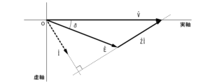
- FIG. 18 is a diagram showing an example of load angles according to the tenth embodiment of the present disclosure.
- the induced voltage vector ⁇ can be calculated from the voltage vector V ⁇ and the current vector Î ⁇ in the same manner as in the eighth embodiment, using the above equation (18).
- the electrical angular frequency ⁇ e of the voltage V is used to calculate the impedance in Equation (19).
- the power converter 4 uses the electrical angle (load angle ⁇ ) of the induced voltage vector input from the control device 3 instead of calculating the load angle ⁇ in the arithmetic function unit 41. to calculate the corrected value of the frequency command value.
- the induced voltage vector estimator 312 calculates the load angle ⁇ based on the voltage and current of the electric power that drives the synchronous machine 2 and the electrical angular frequency of the voltage. presume.
- variable speed power plant 1 can eliminate the need to measure the first angle of the first rotor 22 . Thereby, the cost of the first angle sensor 13 and wiring can be reduced.
- variable speed power plant 1 according to an eleventh embodiment of the present disclosure will be described.
- the same reference numerals are given to the same components as in the above-described embodiment, and detailed description thereof will be omitted.
- FIG. 19 is a diagram showing a functional configuration of a variable speed power plant according to an eleventh embodiment of the present disclosure. As shown in FIG. 19 , the control device 3 according to this embodiment further has an impedance changing section 33 .
- FIG. 19 exemplifies a mode in which the impedance changing section 33 is added to the configuration of the tenth embodiment (FIG. 16), the present invention is not limited to this. In another embodiment, an impedance changing section 33 may be added to the configuration of the ninth embodiment (FIG. 13).
- the impedance changing unit 33 changes the impedance value of the armature based on the active power, the reactive power, and the electrical angular frequency ⁇ e of the voltage of the synchronous machine 2 .
- the electrical angular frequency is not limited to voltage.
- the electrical angular frequencies of the current, the first rotor, and the second rotor match the electrical angular frequency of the voltage in the settling state. These electrical angular frequencies may be substituted for the electrical angular frequencies of the voltage.
- the induced voltage vector estimation unit 312 estimates the induced voltage vector based on the current driving the synchronous machine 2, the electrical angle of the voltage, and the changed impedance value.
- Armature impedance is used to estimate the induced voltage vector.
- This impedance is not a constant value, but fluctuates according to the movement of the first rotor 22 and the second rotor 23 and the permeability (permeance) of magnetic flux in the magnetic circuit inside the synchronous machine 2 due to magnetic saturation.
- the value of impedance is changed according to the active power, reactive power, and rotation speed of the synchronous machine 2 .
- the initial value of the impedance is set in a preliminary test.
- the electrical angular frequency of the voltage V may be substituted with the electrical angular frequency of the second rotor.
- the active power P is the power that drives the load, and is calculated by the following equation (23) from the voltage vector V ⁇ and the current vector Î ⁇ .
- the reactive power Q is power that is mainly stored as magnetic energy instead of driving the load, and is calculated by the following equation (24).
- Im represents the imaginary part of a complex number.
- variable speed power plant 1 further includes the impedance changing unit 33 that changes the impedance value based on the active power, the reactive power, and the electrical angular frequency of the voltage of the synchronous machine 2.
- the induced voltage vector estimator 312 estimates the induced voltage vector based on the current driving the synchronous machine 2, the electrical angle of the voltage, and the changed impedance value.
- variable speed power plant 1 can reflect the change in impedance in the calculation of the induced voltage vector, so that the induced voltage vector can be estimated more accurately.
- variable speed power plant 1 according to a twelfth embodiment of the present disclosure will be described.
- the same reference numerals are given to the same components as in the above-described embodiment, and detailed description thereof will be omitted.
- FIG. 20 is a diagram showing the functional configuration of a variable speed power plant according to the twelfth embodiment of the present disclosure.
- the control device 3 according to this embodiment is an improvement of the control device 3 according to the ninth embodiment. Specifically, as shown in FIG. 20 , the control device 3 according to this embodiment further includes a phase compensator 314 in addition to the induced voltage vector estimator 312 .
- the phase compensator 314 (phase compensator) generates a phase compensation signal for compensating the inertia of the first rotor 22 based on the electrical angle of the second rotor 23 .
- the induced voltage vector estimator 312 calculates the first rotor 22 Estimate the electrical angle ⁇ e1 of .
- the magnetic geared motor has a first rotor 22 and a second rotor 23 .
- the armature is common to the two rotors. Therefore, for example, even if power is applied from the armature to the second rotor 23, a portion of the power excites the motion of the first rotor 22, causing the first rotor 22 to vibrate.
- the present embodiment aims at suppressing the vibration of the first rotor 22 by applying a damping force to the first rotor 22 .
- the induced voltage vector E 1 ⁇ of the first rotor 22 coincides with the voltage vector V ⁇ in the stable state. However, the two do not coincide because in transient conditions the first rotor 22 also uses power to accelerate or decelerate its own inertia. Therefore, the induced voltage vector E 1 ⁇ of the first rotor 22 is estimated from equation (25).
- Equation (26) the induced voltage vector of the first rotor 22 is expressed by Equation (26).
- Equation (27) the angle of the induced voltage vector, that is, the electrical angle ⁇ e1 of the first rotor 22 is obtained by Equation (27).
- the phase compensator 314 calculates and outputs a compensating torque based on the electrical angle ⁇ e1 of the first rotor 22 .
- the compensating torque TD is generated in proportion to the speed of the first rotor 22, for example, as shown in Equation (28).
- kD and ⁇ D are adjustment constants.
- s is the Laplacian operator.
- FIG. 21 is a diagram illustrating a functional configuration of a power converter according to the twelfth embodiment of the present disclosure. As shown in FIG. 21, the electric power converter 4 receives the compensating torque, and the calculation function unit 41 subtracts the torque compensation signal from the torque command output by the speed controller to calculate the compensated torque command. The vector controller adjusts the power frequency and voltage according to the compensated torque command.
- the induced voltage angle estimator 31 calculates the electric angle of the induced voltage based on the voltage, the current, and the electrical angle frequency of the electric power that drives the synchronous machine 2 . Estimate the electrical angle ⁇ e1 of the first rotor 22 in addition to the angle.
- variable speed power plant 1 can damp the vibration of the first rotor 22 and the like while suppressing the step-out of the synchronous machine 2 .
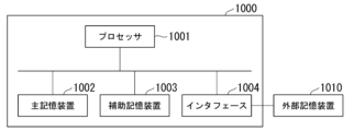
- FIG. 22 is a diagram illustrating an example of a hardware configuration of equipment that constitutes a variable speed power plant according to at least one embodiment of the present disclosure.
- An example of the hardware configuration of the control device 3, the power converter 4, and the second power converter 8 that configure the variable speed power plant 1 will be described below with reference to FIG.
- the computer 1000 comprises a processor 1001, a main storage device 1002, an auxiliary storage device 1003, and an interface 1004.
- the control device 3, the power converter 4, and the second power converter 8 described in each of the above-described embodiments are each implemented in the computer 1000.
- the operation of each processing unit described above is stored in the auxiliary storage device 1003 in the form of a program.
- the processor 1001 reads out the program from the auxiliary storage device 1003, develops it in the main storage device 1002, and executes the above processing according to the program.
- the processor 1001 secures storage areas used for various processes in the main storage device 1002 according to programs.
- the processor 1001 secures a storage area for storing data being processed in the auxiliary storage device 1003 according to the program.
- the program may be for realizing part of the functions that the computer 1000 exhibits.
- the program may function in combination with another program already stored in the auxiliary storage device 1003 or in combination with another program installed in another device.
- the computer 1000 may include a custom LSI (Large Scale Integrated Circuit) such as a PLD (Programmable Logic Device) in addition to or instead of the above configuration.
- PLDs include PAL (Programmable Array Logic), GAL (Generic Array Logic), CPLD (Complex Programmable Logic Device), and FPGA (Field Programmable Gate Array).
- part or all of the functions implemented by processor 1001 may be implemented by the integrated circuit.
- auxiliary storage device 1003 examples include HDD (Hard Disk Drive), SSD (Solid State Drive), magnetic disk, magneto-optical disk, CD-ROM (Compact Disc Read Only Memory), DVD-ROM (Digital Versatile Disc Read Only memory), semiconductor memory, and the like.
- Auxiliary storage device 1003 may be an internal medium directly connected to the bus of computer 1000, or an external storage device 1010 connected to computer 1000 via interface 1004 or a communication line. Further, when this program is distributed to the computer 1000 via a communication line, the computer 1000 receiving the distribution may develop the program in the main storage device 1002 and execute the above process.
- secondary storage 1003 and external storage 1010 are non-transitory, tangible storage media.
- variable speed power plant and control method described in the above embodiments are understood as follows.
- the variable speed power plant (1) includes a stator (21) provided with armature windings (212) to form an armature, magnetic poles (222) and a second rotor (23) provided between the first rotor (22) and the stator (21) to drive the load
- the electrical angle of the induced voltage generated in the armature is estimated based on the rotor (2), the first angle of the first rotor (22), and the second angle of the second rotor (23).
- An induced voltage angle estimator (31) and a power converter (4) that adjusts the frequency of power for driving a synchronous machine (2) based on the estimated electrical angle of the induced voltage.
- the induced voltage angle estimator (31) based on the first angle and the second angle, A flux linkage estimator (310) for estimating the angle of the flux linkage interlinking with the armature winding (212), and a calculator (311) for estimating the electrical angle of the induced voltage based on the angle of the flux linkage.
- the magnetic flux linkage estimator (310) is provided in the first rotor (22) Angle of interlinkage magnetic flux based on the first angle measured by the first angle sensor (13) and the second angle measured by the second angle sensor (14) provided on the second rotor (23) to estimate
- the second angle sensor (14) provided in the second rotor (23) measures It further comprises a first angle estimator (32) for estimating the first angle based on the obtained second angle and the electrical angle of the voltage that drives the synchronous machine (2).
- the first rotor (22) has a lightening portion formed around the rotating shaft. (223).
- the length of the lightening portion (223) in the radial direction of the first rotor (22) is set to be longer as it approaches the center of the magnetic poles (222) of the first rotor (22).
- the first rotor (22) includes the center of the magnetic poles (222) It further has a damper winding (224) wound to interlink magnetic flux in the meridional plane.
- variable speed power plant (1) is mechanically connected to the first rotor (22) of the synchronous machine (2) having a third rotor (51) and an electrical line (52) electrically connected in parallel with the armature winding (212) of the synchronous machine (2), synchronous with the synchronous machine (2);
- a first electric motor (5) having the same speed or the same number of poles as the synchronous machine (2) is further provided.
- variable speed power plant (1) according to the fourth aspect further includes a reduction gear (6) connected to the synchronous machine (2), the reduction gear ( 6) has a joint (63) connecting the first rotor (22) and the second rotor (23) of the synchronous machine (2).
- variable speed power plant (1) includes the second electric motor connected to the first rotor (22) of the synchronous machine (2). (7) and a second power converter (8) that adjusts the frequency of power for driving the second electric motor (7) based on the second angle of the second rotor (23) of the synchronous machine (2). And further comprising.
- the variable speed power plant (1) includes a stator (21) provided with an armature winding (212) to form an armature, a magnetic pole (222) and a second rotor (23) provided between the first rotor (22) and the stator (219); Based on the electrical angle of the first rotor (22) and the electrical angle of the second rotor (23), whichever has the greater absolute value of the offset from the electrical angle of the voltage driving the synchronous machine (2) and a power converter (4) that performs V/f control and adjusts the frequency of the power that drives the synchronous machine (2).
- a stator (21) provided with armature windings (212) to form an armature and a first rotor (22) having magnetic poles (222) ) and a second rotor (23) provided between the first rotor (22) and the stator (21) to drive a load
- a control method for a synchronous machine (2) comprising: estimating the electrical angle of the induced voltage generated in the armature based on the first angle of the first rotor (22) and the second angle of the second rotor (23); and adjusting the frequency of power for driving the synchronous machine (2) based on the electrical angle of the induced voltage.
- variable speed power plant and control method it is possible to suppress step-out of the synchronous machine.
- Variable speed power unit 11 Power line 13 First angle sensor 14 Second angle sensor 2 Synchronous machine 21 Stator 211 Teeth 212 Armature winding 213 Magnet 22 First rotor 221 Core 222 Magnetic pole 223 Lightening part 224 Damper winding 23 second rotor 231 magnetic pole 232 non-magnetic portion 24 output shaft 3 control device 31 induced voltage angle estimator 310 interlinkage magnetic flux estimator 311 calculator 312 induced voltage vector estimator 314 phase compensator 315 load angle estimator 32 1 Angle estimating unit 33 Impedance changing unit 4 Power converter 41 Arithmetic function unit 5 First electric motor 51 Rotor (third rotor) 52 electric wire 6 reduction gear 61 first gear 62 second gear 63 joint 64 shaft 7 second electric motor 71 rotor (fourth rotor) 8 second power converter 1000 computer 1001 processor 1002 main storage device 1003 auxiliary storage device 1004 interface 1010 external storage device
Landscapes
- Engineering & Computer Science (AREA)
- Power Engineering (AREA)
- Control Of Ac Motors In General (AREA)
Abstract
Description
本願は、2021年10月20日に日本に出願された特願2021-171614号について優先権を主張し、その内容をここに援用する。
以下、本開示の第1の実施形態に係る可変速動力装置1について、図を参照しながら説明する。
図1は、本開示の第1の実施形態に係る可変速動力装置の機能構成を示す図である。
図1に示すように、可変速動力装置1は、同期機2と、制御装置3と、電力変換器4とを備えている。
図1及び図2に示すように、同期機2は、固定子21と、第1の回転子22と、第2の回転子23と、出力軸24と、出力軸24Aを有している。
次に、本実施形態に係る制御装置3の動作について詳細に説明する。一例として、第1の回転子22はコア221の外周面を全て覆うように永久磁石を配置した構成について具体的に説明する。まず、鎖交磁束推定部310が実行する鎖交磁束の角度推定について説明する。一般の同期機は、第2の回転子を有さないので、鎖交磁束の角度は第1の回転子から直ちに定まる。このため角度推定の必要はない。角度推定は磁気ギアードモータのように複数の回転子を有するものに有効である。説明を簡単にするため、第1の回転子の角度は、その起磁力が最大になる方向を基準にすると、第1の回転子の基準方向から角度θ進んだ位置の起磁力は次式(1)で近似できる。ここに、p1は第1の回転子の極数である。磁石を有する回転子については、回転子の機械的な角度に極数を2で除した値を乗じたものは電気角と呼ばれる。回転子が機械的に1回転する間に、起磁力は電気角に従ってp1/2交番する。


図3は、本開示の第1の実施形態に係る電力変換器の動作の概念を説明するための図である。本実施形態では、出力軸は第2の回転子に接続される。
電力変換器4は、誘起電圧の電気角に基づくベクトル制御により同期機2を制御する例である。ベクトル制御は、一般に、同期機2の出力トルクを調節する。出力トルクの指令値は、ベクトル制御の上位に配置した速度制御器が出力する。速度制御器は、速度指令を表す電力の周波数指令と負荷軸の電気角周波数を入力し、例えば、比例積分制御の演算によりトルク指令を出力する。本実施形態では、第2の回転子23が負荷軸に相当する。ベクトル制御器は誘起電圧の電気角と電力変換器4が出力する電力の電流とに基づき、電圧指令と周波数指令を出力する。電力変換器4は、電圧指令と周波数指令に従って電機子に電力を供給する。
以上のように、本実施形態に係る可変速動力装置1は、同期機2の第1の回転子22の角度と、第2の回転子23の角度とから電機子に発生する誘起電圧の電気角を推定する誘起電圧角度推定部31と、推定された誘起電圧の電気角に基づいて、同期機2を駆動する電力の周波数を調整する電力変換器4とを備える。
また、本実施形態に係る誘起電圧角度推定部31は、第1の回転子22の角度及び第2の回転子23の角度に基づいて電機子巻線212に鎖交する磁束の角度を推定する鎖交磁束推定部310と、鎖交磁束の角度及び第2の回転子23の角度に基づいて誘起電圧の電気角を算出する算出部311とを有する。
本実施形態によると、第1の回転子の角度と第2の回転子の角度に基づき推定した誘起電圧の電気角を用いてベクトル制御を行い、ベクトル制御本来の速応性により磁気ギアードモータの速応性を改善し、または、脱調を防止する効果が得られる。
次に、本開示の第2の実施形態に係る可変速動力装置1について説明する。
上述の実施形態と共通の構成要素には同一の符号を付して詳細説明を省略する。
図4に示すように、本実施形態に係る制御装置3は、第1角度推定部32をさらに有している。第1角度推定部32は、例えば、試験や解析により事前に定める調整定数β1とβ2とを用いて、第2角度センサ14が測定した第2の回転子23の角度(第2角度)と電圧の電気角θVとに基づいて、第1の回転子22の角度(第1角度)を推定する。
次に、本実施形態に係る制御装置3の動作について詳細に説明する。本実施形態に係る制御装置3は、第1の回転子22の第1角度センサ13の代わりに、第2の回転子23の角度と、三相交流の電圧及び電流とから第1の回転子22の角度を推定する第1角度推定部32を用いる。

以上のように、本実施形態に係る可変速動力装置1は、第2の回転子23の角度に基づいて第1の回転子22の角度を推定する第1角度推定部32をさらに備える。
次に、本開示の第3の実施形態に係る可変速動力装置1について説明する。本実施形態では、出力軸は第2の回転子に接続される。
上述の実施形態と共通の構成要素には同一の符号を付して詳細説明を省略する。
図5は、本開示の第3の実施形態に係る第1の回転子の断面図である。
図5に示すように、本実施形態に係る第1の回転子22は、回転軸Oの周囲に形成された肉抜き部223を有している。肉抜き部223は、第1の回転子22のコア221を肉抜きして形成したものである。


以上のように、本実施形態に係る可変速動力装置1において、第1の回転子22は、回転軸Oの周囲に肉抜き部223を有する。
次に、本開示の第4の実施形態に係る可変速動力装置1について説明する。本実施形態では、出力軸は第2の回転子に接続される。
上述の実施形態と共通の構成要素には同一の符号を付して詳細説明を省略する。
図6は、本開示の第4の実施形態に係る第1の回転子の断面図である。
図7は、本開示の第4の実施形態に係る第1の回転子の斜視図である。
図6~図7に示すように、本実施形態に係る第1の回転子22は、磁極222の中央を含む子午面内を貫く磁束と鎖交されるように巻回した制動巻線224をさらに有している。


以上のように、本実施形態に係る可変速動力装置1において、第1の回転子22は、磁極222の中央を含む子午面内を貫く磁束と鎖交するように巻回した制動巻線224をさらに有する。
次に、本開示の第5の実施形態に係る可変速動力装置1について説明する。本実施形態では、出力軸は第2の回転子に接続される。
上述の実施形態と共通の構成要素には同一の符号を付して詳細説明を省略する。
図8は、本開示の第5の実施形態に係る可変速動力装置の機能構成を示す図である。
図8に示すように、本実施形態に係る可変速動力装置1は、第2の実施形態に係る構成に加えて、第1電動機5をさらに備えている。第1電動機5は、回転子51(第3の回転子)と、電気線52とを有している。なお、第1電動機5は、たとえば誘導電動機である。第1電動機5は、同期機2と同期速度が等しくなるように、または、同期機2と極数が等しくなるように構成される。
第3~第4の実施形態では、第1の回転子22の肉抜き部223及び制動巻線224により、第1の回転子22の運動の減衰比を改善した。しかし、第1の回転子22は同期機2の内部にあるので場所の制約から、肉抜き部223や、制動巻線224だけでは十分に改善できない場合もある。
以上のように、本実施形態に係る可変速動力装置1は、同期機2の第1の回転子22と極数が同数であり、第1の回転子22と機械的に接続される回転子51(第3の回転子)と、同期機2の電機子巻線212と電気的に並列に接続される電気線52と、を有する第1電動機5をさらに備える。
次に、本開示の第6の実施形態に係る可変速動力装置1について説明する。本実施形態では、出力軸は第2の回転子に接続される。
上述の実施形態と共通の構成要素には同一の符号を付して詳細説明を省略する。
図9は、本開示の第6の実施形態に係る可変速動力装置の機能構成を示す図である。
図9に示すように、本実施形態に係る可変速動力装置1は、第2の実施形態に係る構成に加えて、減速機6をさらに備えている。
以上のように、本実施形態に係る可変速動力装置1は、同期機に接続される減速機6をさらに備える。減速機6は、同期機2の第1の回転子22及び前記第2の回転子を接続する継手63を有する。
次に、本開示の第7の実施形態に係る可変速動力装置1について説明する。本実施形態では、出力軸は第2の回転子に接続される。
上述の実施形態と共通の構成要素には同一の符号を付して詳細説明を省略する。
図10は、本開示の第7の実施形態に係る可変速動力装置の機能構成を示す図である。
図10に示すように、本実施形態に係る可変速動力装置1は、第2の実施形態に係る構成に加えて、第2電動機7と、第2電力変換器8とをさらに備えている。
図10に示すように、同期機2の第1の回転子22には、第2電動機7が接続されている。第2電動機7は、第2電力変換器8により電力が供給される。第2電力変換器8は、同期機2の第2の回転子23の角度の時間微分値から得る第2の回転子23の回転数[rps]にp1n12/2を乗じて、第2の回転子23の回転数が第1の回転子22の同期回転数となるよう第2電力変換器8の目標周波数を生成する。第2電力変換器8は、第1の回転子22の回転数が、同期回転数に一致するように第2電動機7を駆動する電力の周波数や位相を調整する。さらに、第2電力変換器8は、同期機2を助勢するよう第2電動機7に電力を駆動する電力の電圧を追加的に進相させても良い。
以上のように、本実施形態に係る可変速動力装置1は、同期機2の第1の回転子22と機械的に接続される第2電動機7と、同期機2の第2の回転子23の速度に一致するように、第2電動機7を駆動する電力の周波数を調整する第2電力変換器8とをさらに備える。第2電力変換器8が第2電動機7に供給する電力は、第2電動機7および第1の回転子22が第2の回転子23に対して相対運動する場合には減衰力として作用し、この相対運動が制限される。さらに、第2電力変換器8と第2電動機7によって同期機2を助勢すると負荷の駆動能力が向上する。
次に、本開示の第8の実施形態に係る可変速動力装置1について説明する。
上述の実施形態と共通の構成要素には同一の符号を付して詳細説明を省略する。
図11は、本開示の第8の実施形態に係る可変速動力装置の機能構成を示す図である。
図11に示すように、本実施形態に係る可変速動力装置1は、鎖交磁束推定部310を有さない。鎖交磁束推定部310は、第1の回転子22と第2の回転子23とによる誘起電圧の電気角に基づいて、電力変換器4でベクトル制御を実施した。本実施形態では、電力変換器4において、ベクトル制御に変えてV/f制御を用いることにより、誘起電圧の電気角の推定を不要とする。同期機の回転速度は駆動電力の周波数の同期速度に時間的に遅れをもって追従し、最終的に同期速度で整定することが知られている。本願の磁気ギアードモータも同期機に属すのでこの性質を有している。
以上のように、本実施形態に係る可変速動力装置1において、電力変換器4は、第1の回転子22の電気角および第2の回転子23の電気角のうち、電圧の電気角とのオフセットの絶対値が大きい方に基づいてV/f制御を行い、同期機2を駆動する電力の周波数を調整する。
次に、本開示の第9の実施形態に係る可変速動力装置1について説明する。
上述の実施形態と共通の構成要素には同一の符号を付して詳細説明を省略する。
図13に示すように、本実施形態に係る制御装置3は、誘起電圧ベクトル推定部312を有している。
図14に示すように、本実施形態に係る電力変換器4は、演算機能部41に、ベクトル制御器に加え負荷調整器411を有する。負荷調整器411の具体的な構成は、第8の実施形態と同様である。
次に、本実施形態に係る制御装置3の動作について詳細に説明する。誘起電圧ベクトル推定部312は、電機子に発生する誘起電圧ベクトルを、電圧ベクトル及び電流ベクトルと、電機子のインピーダンスとから推定する。電流ベクトルと電圧ベクトルは、第2の回転子の電気角θeから、それぞれ式(12)、式(13)で算出する。


図15は、第1の回転子22の影響により誘起電圧ベクトルの角度が、第2の回転子23の電気角に対してオフセットする様子を表している。図15は、第1の回転子22の誘起電圧ベクトルE1^・と第2の回転子23の誘起電圧ベクトルE2^・の和である誘起電圧ベクトルE^・の電気角が実軸となるよう描いている、δは電圧ベクトルV^・と誘起電圧ベクトルE^・の成す角度であり、負荷角と呼ばれる値である。εは誘起電圧E^・と第2の回転子23の誘起電圧の成す角度である。
以上のように、本実施形態に係る可変速動力装置1において、誘起電圧ベクトル推定部312は、同期機2を駆動する電圧及び電流と、に基づいて、誘起電圧ベクトルを推定し、誘起電圧の電気角を出力する。
次に、本開示の第10の実施形態に係る可変速動力装置1について説明する。
上述の実施形態と共通の構成要素には同一の符号を付して詳細説明を省略する。
図16に示すように、本実施形態に係る誘起電圧ベクトル推定部312は、同期機2を駆動する電力の電圧、電流及び電圧の電気角周波数に基づいて、負荷角δを推定する。本実施形態では、第2の回転子23の第2角度センサ14は不要である。
第9の実施形態では、第2の回転子23の角度を測るための第2角度センサ14が必要であり、センサや配線のコストがかかった。一方、本実施形態は、角度を測るセンサや配線のコストを不要とする。具体的に、本実施形態では、電圧ベクトルを基準にして、電流ベクトルと誘起電圧ベクトルを計算する。
電圧は電力変換器4の内部にある電圧の電気角指令に一致するように電力変換器4が出力する。よって、電圧の電気角は電圧の電気角指令θVをそのまま用いる。電圧の振幅は電力変換器4の内部にある指令値|V|に従うとして、実軸をθvにとると、電圧ベクトルは次式(21)で表される。

誘起電圧ベクトルE^・は、第8の実施形態と同様に、電圧ベクトルV^・と電流ベクトルI^・から、上記した式(18)で計算できる。式(19)におけるインピーダンスの計算には電圧Vの電気角周波数ωeを用いる。本実施形態では、電圧ベクトルを基準に表しているので、図18に示すように、誘起電圧ベクトルの電気角は負荷角δである。したがって、図17に示すように、電力変換器4は、演算機能部41において負荷角δを計算するのではなく、制御装置3から入力された誘起電圧ベクトルの電気角(負荷角δ)を使って周波数指令値の修正値を算出する。
以上のように、本実施形態に係る可変速動力装置1において、誘起電圧ベクトル推定部312は、同期機2を駆動する電力の電圧、電流及び電圧の電気角周波数に基づいて、負荷角δを推定する。
次に、本開示の第11の実施形態に係る可変速動力装置1について説明する。
上述の実施形態と共通の構成要素には同一の符号を付して詳細説明を省略する。
図19に示すように、本実施形態に係る制御装置3は、インピーダンス変更部33をさらに有している。なお、図19には、第10の実施形態の構成(図16)にインピーダンス変更部33を加えた態様が例示されているが、これに限られることはない。他の実施形態では、第9の実施形態の構成(図13)にインピーダンス変更部33を加えた態様であってもよい。
誘起電圧ベクトルの推定には電機子のインピーダンスを用いる。このインピーダンスは、一定値ではなく、第1の回転子22と第2の回転子23の運動や、磁気飽和により同期機2内部の磁気回路の磁束の通り易さ(パーミアンス)により変動する。本実施形態では、同期機2の有効電力、無効電力、及び回転数に応じて、インピーダンスの値を変更する。
以上のように、本実施形態に係る可変速動力装置1は、同期機2の有効電力と、無効電力と、電圧の電気角周波数とに基づいてインピーダンスの値を変更するインピーダンス変更部33をさらに有している。また、誘起電圧ベクトル推定部312は、同期機2を駆動する電流と、電圧の電気角と、変更したインピーダンスの値とに基づいて誘起電圧ベクトルを推定する。
次に、本開示の第12の実施形態に係る可変速動力装置1について説明する。
上述の実施形態と共通の構成要素には同一の符号を付して詳細説明を省略する。
本実施形態に係る制御装置3は、第9の実施形態に係る制御装置3を改良したものである。具体的には、図20に示すように、本実施形態に係る制御装置3は、誘起電圧ベクトル推定部312に加えて、位相補償部314をさらに有している。
磁気ギアードモータは、第1の回転子22と第2の回転子23を有する。二つの回転子に対し、電機子は共通である。このため、例えば第2の回転子23に電機子から動力を与えようとしても、その一部は第1の回転子22の運動を励起し、第1の回転子22は振動する。本実施形態は、第1の回転子22に減衰力を与えて、第1の回転子22の振動を抑制することが狙いである。


図21は、本開示の第12の実施形態に係る電力変換器の機能構成を示す図である。
図21に示すように、電力変換器4は補償トルクを入力し、演算機能部41において、速度制御器が出力するトルク指令からトルク補償信号を差し引いて、補償後のトルク指令を演算する。ベクトル制御器は補償後のトルク指令に従って、電力の周波数と電圧を調節する。
以上のように、本実施形態に係る可変速動力装置1において、誘起電圧角度推定部31は、同期機2を駆動する電力の電圧、電流及び電圧の電気角周波数に基づいて、誘起電圧の電気角に加えて第1の回転子22の電気角θe1を推定する。
図22は、本開示の少なくとも一の実施形態に係る可変速動力装置を構成する機器のハードウェア構成の一例を示す図である。
以下、図22を参照しながら、可変速動力装置1を構成する制御装置3、電力変換器4、及び第2電力変換器8のハードウェア構成の一例について説明する。
上述の実施形態に記載の可変速動力装置及び制御方法は、例えば以下のように把握される。
11 電力線
13 第1角度センサ
14 第2角度センサ
2 同期機
21 固定子
211 歯
212 電機子巻線
213 磁石
22 第1の回転子
221 コア
222 磁極
223 肉抜き部
224 制動巻線
23 第2の回転子
231 磁極
232 非磁性部
24 出力軸
3 制御装置
31 誘起電圧角度推定部
310 鎖交磁束推定部
311 算出部
312 誘起電圧ベクトル推定部
314 位相補償部
315 負荷角推定部
32 第1角度推定部
33 インピーダンス変更部
4 電力変換器
41 演算機能部
5 第1電動機
51 回転子(第3の回転子)
52 電気線
6 減速機
61 第1ギア
62 第2ギア
63 継手
64 軸
7 第2電動機
71 回転子(第4の回転子)
8 第2電力変換器
1000 コンピュータ
1001 プロセッサ
1002 主記憶装置
1003 補助記憶装置
1004 インタフェース
1010 外部記憶装置
Claims (12)
- 電機子巻線が設けられて電機子を形成する固定子と、磁極を有する第1の回転子と、前記第1の回転子と前記固定子との間に設けられて負荷を駆動する第2の回転子と、を有する同期機と、
前記第1の回転子の第1角度と、前記第2の回転子の第2角度とに基づいて、前記電機子に発生する誘起電圧の電気角を推定する誘起電圧角度推定部と、
推定された前記誘起電圧の電気角に基づいて、前記同期機を駆動する電力の周波数を調整する電力変換器と、
を備える可変速動力装置。 - 前記誘起電圧角度推定部は、
前記第1角度及び前記第2角度に基づいて、前記電機子巻線に鎖交する鎖交磁束の角度を推定する鎖交磁束推定部と、
前記鎖交磁束の角度に基づいて、前記誘起電圧の電気角を算出する算出部と、
を有する請求項1に記載の可変速動力装置。 - 前記鎖交磁束推定部は、前記第1の回転子に設けられた第1角度センサが測定した前記第1角度と、前記第2の回転子に設けられた第2角度センサが測定した前記第2角度とに基づいて前記鎖交磁束の角度を推定する、
請求項2に記載の可変速動力装置。 - 前記第2の回転子に設けられた第2角度センサが測定した前記第2角度と、前記同期機を駆動する電圧の電気角とに基づいて前記第1角度を推定する第1角度推定部をさらに備える、
請求項2に記載の可変速動力装置。 - 前記第1の回転子は、回転軸の周囲に形成された肉抜き部を有する、
請求項4に記載の可変速動力装置。 - 前記肉抜き部の前記第1の回転子の径方向の長さは、前記第1の回転子の前記磁極の中央に近付くほど長くなるように設定される、
請求項5に記載の可変速動力装置。 - 前記第1の回転子は、前記磁極の中央を含む子午面内を貫く磁束と鎖交するように巻回した制動巻線をさらに有する、
請求項5または6に記載の可変速動力装置。 - 前記同期機の前記第1の回転子に機械的に接続される第3の回転子と、前記同期機の前記電機子巻線と電気的に並列に接続される電気線と、を有し、前記同期機と同期速度が等しい、または、前記同期機と極数が等しい第1電動機をさらに備える、
請求項4に記載の可変速動力装置。 - 前記同期機に接続される減速機をさらに備え、
前記減速機は、前記同期機の前記第1の回転子と前記第2の回転子とを接続する継手を有する、
請求項4に記載の可変速動力装置。 - 前記同期機の前記第1の回転子に接続される第2電動機と、
前記同期機の前記第2の回転子の前記第2角度に基づいて、前記第2電動機を駆動する電力の周波数を調整する第2電力変換器と、
をさらに備える請求項4に記載の可変速動力装置。 - 電機子巻線が設けられて電機子を形成する固定子と、磁極を有する第1の回転子と、前記第1の回転子と前記固定子との間に設けられる第2の回転子と、を有する同期機と、
前記第1の回転子の電気角および前記第2の回転子の電気角のうち、前記同期機を駆動する電圧の電気角とのオフセットの絶対値が大きい方に基づいてV/f制御を行い、前記同期機を駆動する電力の周波数を調整する電力変換器と、
を備える可変速動力装置。 - 電機子巻線が設けられて電機子を形成する固定子と、磁極を有する第1の回転子と、前記第1の回転子と前記固定子との間に設けられて負荷を駆動する第2の回転子と、を有する同期機の制御方法であって、
前記第1の回転子の第1角度と、前記第2の回転子の第2角度とに基づいて、前記電機子に発生する誘起電圧の電気角を推定するステップと、
推定された前記誘起電圧の電気角に基づいて、前記同期機を駆動する電力の周波数を調整するステップと、
を有する制御方法。
Applications Claiming Priority (2)
| Application Number | Priority Date | Filing Date | Title |
|---|---|---|---|
| JP2021-171614 | 2021-10-20 | ||
| JP2021171614 | 2021-10-20 |
Publications (1)
| Publication Number | Publication Date |
|---|---|
| WO2023067882A1 true WO2023067882A1 (ja) | 2023-04-27 |
Family
ID=86059030
Family Applications (1)
| Application Number | Title | Priority Date | Filing Date |
|---|---|---|---|
| PCT/JP2022/031347 WO2023067882A1 (ja) | 2021-10-20 | 2022-08-19 | 可変速動力装置及び制御方法 |
Country Status (1)
| Country | Link |
|---|---|
| WO (1) | WO2023067882A1 (ja) |
Citations (6)
| Publication number | Priority date | Publication date | Assignee | Title |
|---|---|---|---|---|
| WO2015186714A1 (ja) | 2014-06-02 | 2015-12-10 | 国立大学法人大阪大学 | 回転電機及び回転電機の制御装置 |
| WO2019022100A1 (ja) * | 2017-07-26 | 2019-01-31 | パナソニック株式会社 | 回転電機 |
| CN110880893A (zh) * | 2019-12-09 | 2020-03-13 | 华中科技大学 | 一种磁齿轮电机控制方法及控制电路 |
| CN111030531A (zh) * | 2019-12-26 | 2020-04-17 | 滨州学院 | 复合电机运行控制方法和控制系统 |
| US20210265905A1 (en) * | 2018-04-26 | 2021-08-26 | Ebm-Papst Mulfingen Gmbh & Co. Kg | Electrical Machine with Electric Motor and Magnetic Gear |
| JP2021171614A (ja) | 2020-04-25 | 2021-11-01 | 文夫 小板橋 | ネオジウム磁石を使用した鉄粉集塵マスク |
-
2022
- 2022-08-19 WO PCT/JP2022/031347 patent/WO2023067882A1/ja active Application Filing
Patent Citations (6)
| Publication number | Priority date | Publication date | Assignee | Title |
|---|---|---|---|---|
| WO2015186714A1 (ja) | 2014-06-02 | 2015-12-10 | 国立大学法人大阪大学 | 回転電機及び回転電機の制御装置 |
| WO2019022100A1 (ja) * | 2017-07-26 | 2019-01-31 | パナソニック株式会社 | 回転電機 |
| US20210265905A1 (en) * | 2018-04-26 | 2021-08-26 | Ebm-Papst Mulfingen Gmbh & Co. Kg | Electrical Machine with Electric Motor and Magnetic Gear |
| CN110880893A (zh) * | 2019-12-09 | 2020-03-13 | 华中科技大学 | 一种磁齿轮电机控制方法及控制电路 |
| CN111030531A (zh) * | 2019-12-26 | 2020-04-17 | 滨州学院 | 复合电机运行控制方法和控制系统 |
| JP2021171614A (ja) | 2020-04-25 | 2021-11-01 | 文夫 小板橋 | ネオジウム磁石を使用した鉄粉集塵マスク |
Similar Documents
| Publication | Publication Date | Title |
|---|---|---|
| JP3720357B2 (ja) | 交流機械の駆動装置において変換器を使用せずに磁束、位置及び速度を推定する方法及び装置 | |
| JP4221307B2 (ja) | 同期電動機の制御装置,電気機器およびモジュール | |
| JP5576145B2 (ja) | モータ制御装置 | |
| JP5332400B2 (ja) | 電動機のトルク脈動抑制装置および抑制方法 | |
| JP2008271740A (ja) | モータ制御装置 | |
| JP6568658B2 (ja) | 回転電動機の制御方法および制御装置、並びに回転電動機駆動システム | |
| BR112013022009B1 (pt) | método e sistema para controlar um motor elétrico em condições operacionais de estol ou próximo das mesmas | |
| EP3454469B1 (en) | Torque ripple reduction for a generator and wind turbine including the same | |
| US9793844B2 (en) | Permanent magnet motor controller | |
| JP5033662B2 (ja) | 電動機駆動システム | |
| EP3258594B1 (en) | Controlling a multiple-set electrical machine | |
| JP2011176951A (ja) | モータのトルク制御装置 | |
| US20130200839A1 (en) | Rectifier based torsional mode damping system and method | |
| WO2023067882A1 (ja) | 可変速動力装置及び制御方法 | |
| CN108494198B (zh) | 一种单绕组无轴承开关磁阻电机的控制方法 | |
| CN109639198A (zh) | 一种电机控制方法、系统及电机 | |
| WO2024038628A1 (ja) | 可変速動力装置及び制御方法 | |
| JP6222834B2 (ja) | モータ制御装置 | |
| JP2011019336A (ja) | 電動機制御装置 | |
| JP5744151B2 (ja) | 電動機の駆動装置および電動機の駆動方法 | |
| JP3287147B2 (ja) | 誘導電動機の制御方法 | |
| JP5169014B2 (ja) | 交流電動機のための位相推定法 | |
| JPS6198200A (ja) | 可変速発電システムの励磁制御装置 | |
| Klöck et al. | Modeling and torque ripple minimization of transverse flux machines | |
| CN111894805B (zh) | 针对发电机的位置和速度计算 |
Legal Events
| Date | Code | Title | Description |
|---|---|---|---|
| 121 | Ep: the epo has been informed by wipo that ep was designated in this application |
Ref document number: 22883194 Country of ref document: EP Kind code of ref document: A1 |
|
| WWE | Wipo information: entry into national phase |
Ref document number: 2022883194 Country of ref document: EP |
|
| ENP | Entry into the national phase |
Ref document number: 2022883194 Country of ref document: EP Effective date: 20240411 |
|
| ENP | Entry into the national phase |
Ref document number: 2023554948 Country of ref document: JP Kind code of ref document: A |