WO2023067880A1 - 詰替え容器用栓体及びこれを具備する詰替え容器 - Google Patents
詰替え容器用栓体及びこれを具備する詰替え容器 Download PDFInfo
- Publication number
- WO2023067880A1 WO2023067880A1 PCT/JP2022/030814 JP2022030814W WO2023067880A1 WO 2023067880 A1 WO2023067880 A1 WO 2023067880A1 JP 2022030814 W JP2022030814 W JP 2022030814W WO 2023067880 A1 WO2023067880 A1 WO 2023067880A1
- Authority
- WO
- WIPO (PCT)
- Prior art keywords
- outflow
- plug
- container
- wall
- refill
- Prior art date
- Legal status (The legal status is an assumption and is not a legal conclusion. Google has not performed a legal analysis and makes no representation as to the accuracy of the status listed.)
- Ceased
Links
Images


Classifications
-
- B—PERFORMING OPERATIONS; TRANSPORTING
- B65—CONVEYING; PACKING; STORING; HANDLING THIN OR FILAMENTARY MATERIAL
- B65D—CONTAINERS FOR STORAGE OR TRANSPORT OF ARTICLES OR MATERIALS, e.g. BAGS, BARRELS, BOTTLES, BOXES, CANS, CARTONS, CRATES, DRUMS, JARS, TANKS, HOPPERS, FORWARDING CONTAINERS; ACCESSORIES, CLOSURES, OR FITTINGS THEREFOR; PACKAGING ELEMENTS; PACKAGES
- B65D47/00—Closures with filling and discharging, or with discharging, devices
- B65D47/04—Closures with discharging devices other than pumps
- B65D47/06—Closures with discharging devices other than pumps with pouring spouts or tubes; with discharge nozzles or passages
- B65D47/12—Closures with discharging devices other than pumps with pouring spouts or tubes; with discharge nozzles or passages having removable closures
-
- B—PERFORMING OPERATIONS; TRANSPORTING
- B65—CONVEYING; PACKING; STORING; HANDLING THIN OR FILAMENTARY MATERIAL
- B65D—CONTAINERS FOR STORAGE OR TRANSPORT OF ARTICLES OR MATERIALS, e.g. BAGS, BARRELS, BOTTLES, BOXES, CANS, CARTONS, CRATES, DRUMS, JARS, TANKS, HOPPERS, FORWARDING CONTAINERS; ACCESSORIES, CLOSURES, OR FITTINGS THEREFOR; PACKAGING ELEMENTS; PACKAGES
- B65D47/00—Closures with filling and discharging, or with discharging, devices
- B65D47/04—Closures with discharging devices other than pumps
- B65D47/32—Closures with discharging devices other than pumps with means for venting
-
- B—PERFORMING OPERATIONS; TRANSPORTING
- B65—CONVEYING; PACKING; STORING; HANDLING THIN OR FILAMENTARY MATERIAL
- B65D—CONTAINERS FOR STORAGE OR TRANSPORT OF ARTICLES OR MATERIALS, e.g. BAGS, BARRELS, BOTTLES, BOXES, CANS, CARTONS, CRATES, DRUMS, JARS, TANKS, HOPPERS, FORWARDING CONTAINERS; ACCESSORIES, CLOSURES, OR FITTINGS THEREFOR; PACKAGING ELEMENTS; PACKAGES
- B65D47/00—Closures with filling and discharging, or with discharging, devices
- B65D47/36—Closures with frangible parts adapted to be pierced, torn or removed, to provide discharge openings
Definitions
- the present invention relates to a refill container stopper and a refill container including the same.
- Liquid detergents, shampoos, etc. are generally distributed in containers. From the viewpoint of reducing environmental load, refillable containers are used for refilling containers to be refilled with contents such as liquid detergents. By using this refill container, the container to be refilled can be used for a long period of time without discarding the container to be refilled.
- the operation of refilling the contents with the refilling container is performed by connecting the neck portion of the refilling container provided with the outlet for the contents and the neck portion of the container to be refilled.
- a refilling container plug that is attached to cover the refilling outlet of the refilling container (for example, Patent Document 1: and Patent Document 2).
- the plug for a refill container of Patent Document 1 includes a plug main body including an outflow tube and a mounting tube, and a plug including a mounting wall portion, a closing plate portion, and a push-in projection that are in close contact with the inner peripheral surface of the mounting tube.
- a cover is provided, and the push-in protrusion projects outward in the outflow direction through an insertion opening formed by notching from the opening peripheral edge of the outflow opening to the radially outer side of the outflow tube, and the tip of the push-in protrusion is provided.
- the plug lid is attached to the plug main body with a part of the surface arranged radially outward of the outer peripheral surface of the outflow tube.
- the plug for a refill container disclosed in Patent Document 2 includes a plug main body including an outflow pipe, a cylindrical outer wall, and a mounting pipe, and a mounting wall portion, a closing plate portion, and a push-in convex portion that are in close contact with the inner peripheral surface of the mounting pipe. wherein the push-in protrusion protrudes outward in the outflow direction from the top plate of the plug body, and a part of the tip surface of the push-in protrusion is positioned above the outer peripheral surface of the outflow cylinder. By arranging it radially outward, the plug lid is attached to the plug body, and air is exchanged during refilling via the insertion opening and the outside air communication opening after the push-in protrusion is pushed out. is done.
- the present invention relates to a refillable container plug that is attached to cover a refill outlet of a refillable container for refilling a refillable container having a neck portion.
- the refill container plug includes a plug main body that is joined and fixed to the peripheral edge of the opening of the refill outlet, and an outflow opening that is formed in the top panel of the plug main body and that extends inward in the outflow direction. It is preferable that the plug cover is detachably attached to the plug body.
- the plug body includes an outflow tube that surrounds the outflow opening and protrudes outward in the outflow direction from the top panel, and a top plate that is arranged concentrically with the outflow tube and surrounds the outflow tube.
- the plug main body has an insertion opening that is formed in the top plate at the space between the outflow tube and the cylindrical outer wall.
- the stopper includes: a mounting wall portion whose outer peripheral surface is in close contact with the inner peripheral surface of the mounting cylinder; a blocking plate portion having a planar shape similar to a hollow cross-sectional shape of the mounting cylinder; and the blocking plate.
- the plug for a refill container has the push-in convex portion protrude outward in the outflow direction from the top plate through the insertion opening at the space between the outflow cylinder and the cylindrical outer wall. It is preferable that the plug lid is attached to the plug main body in a closed state.
- the present invention also relates to a refillable container for refilling a refillable container having a neck portion.
- the refill container includes a refill container stopper attached to cover the refill outlet, and the refill container stopper extends from a peripheral opening portion of the refill outlet. and a plug lid detachably attached to the plug body for closing the outflow opening formed in the top panel of the plug body from the inside in the outflow direction.
- the plug body includes an outflow tube that surrounds the outflow opening and protrudes outward in the outflow direction from the top panel, and a top plate that is arranged concentrically with the outflow tube and surrounds the outflow tube.
- the stopper includes: a mounting wall portion whose outer peripheral surface is in close contact with the inner peripheral surface of the mounting cylinder; a blocking plate portion having a planar shape similar to a hollow cross-sectional shape of the mounting cylinder; and the blocking plate. It is preferable to have a push-in convex portion erected from the peripheral edge portion of the portion.
- the plug for a refill container has the push-in convex portion protrude outward in the outflow direction from the top plate through the insertion opening at the space between the outflow cylinder and the cylindrical outer wall. It is preferable that the plug lid is attached to the plug main body in a closed state.
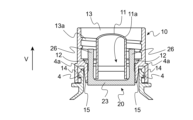
- FIG. 1 is a front view showing one embodiment of a refill container according to the present invention.
- FIG. 2 is a cross-sectional view along the outflow direction showing the neck portion of the refill container of FIG. 1 and a refill container plug attached to cover the outflow port of the neck portion.
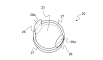
- FIG. 3 is a perspective view of the refill container stopper of FIG. 2 as viewed from the outside in the outflow direction.
- FIG. 4 is a perspective view of the plug lid of the refill container plug shown in FIG. 3 as viewed from the outside in the outflow direction.
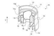
- FIG. 5 is a cross-sectional perspective view of the plug body of the refill container plug shown in FIG. 3 as viewed from the outside in the outflow direction.
- FIG. 6 is a cross-sectional perspective view of the plug body of the refill container plug shown in FIG. 3, viewed from the inside in the outflow direction.
- FIG. 7 is a perspective view of a plug body included in the refill container plug of FIG. 3 as viewed from the inside in the outflow direction.
- FIG. 8 is a perspective view for explaining the refilling operation of refilling the refillable container with the contents using the refillable container of FIG.
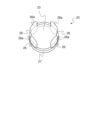
- FIG. 9 is a view equivalent to FIG. 4 showing another embodiment of the plug lid according to the present invention.
- 10A and 10B are diagrams showing another embodiment of the refill container stopper according to the present invention, and FIG. FIG. 10(b) is a cross-sectional view showing the mouth and neck portion during the refilling operation.
- the present invention relates to a plug for a refill container and a refill container having the same, which can efficiently and stably fill the contents during the refilling operation and prevent leakage of the contents.
- FIG. 1 shows one embodiment of the refillable container of the present invention.
- the refilling container 5 of the present embodiment is a refilling container that contains contents such as skin lotion and milky lotion, and is used to refill the refillable container with the contents.
- the refill container 5 of the present embodiment is a thin-walled bottle-shaped container, and includes a body portion 2 having a bottom portion, a neck portion 4 having a refill outlet for discharging the contents, and the neck portion 4 and the body. and a shoulder portion 3 located between the portion 2 .
- the refilling container 5 shown in FIG. 1 is in a self-supporting state in which the bottom of the body 2 is grounded on a horizontal surface and is self-supporting. In such a state, the mouth and neck portion 4 is positioned vertically upward and is arranged to face the bottom portion of the body portion 2 .
- the mouth and neck portion 4 is a cylindrical portion having therein a flow path for discharging contents to the outside, and has openings at both ends in the central axis direction.
- the shoulder 3 has an opening at the center of the upper side in the vertical direction, and a truncated cone that descends while expanding horizontally from the periphery of the opening. It has a shape of In the self-supporting state, the body portion 2 has a cylindrical peripheral wall portion that hangs downward from the entire lower peripheral edge of the shoulder portion 3 and a bottom portion positioned at the lower end of the peripheral wall portion.
- the refill container 5 has an internal space defined by the shoulder portion 3 and the body portion 2, and contents such as lotion, milky lotion, etc. are stored in the internal space.
- the central axis direction of the refill container 5 of this embodiment matches the outflow direction V of the contents when the contents are discharged from the container 5 to the outside.
- the vertical direction Z coincides with the outflow direction V of the content in the refill container 5 .
- the outflow direction V of the contents is hereinafter simply referred to as "outflow direction V".
- the outside of the outflow direction V is also called the “front end side”
- the inside of the outflow direction V is also called the "end end side”.
- the refill container 5 of the present embodiment includes a refill container plug 1 (hereinafter also simply referred to as "plug 1”) attached to cover the refill outlet in the neck portion 4.
- the plug 1 of the present embodiment is fixed to the mouth-neck portion 4 in a state in which the refill outlet of the refill container 4 is sealed. (hereinafter also referred to as "refill neck portion 4") and the neck portion 7 of the container 6 to be refilled (hereinafter also referred to as "refill neck portion 7”) to form a refill outlet. It has a function of communicating with the mouth/neck portion 7 to be refilled. The details of such a refilling operation will be described later.
- the plug 1 comprises a plug main body 10 joined and fixed to the opening peripheral edge portion 4a of the refill outlet in the refill neck portion 4, and a plug lid detachably attached to the plug main body 10. 20.
- the plug body 1 is attached to the refill mouth neck part 4 in a state where the plug lid 20 is attached to the plug body 10.
- the "peripheral portion of the opening of the refill outlet in the refill neck portion 4" is also referred to as the "outlet peripheral portion 4a".
- the plug lid 20 includes a blocking plate portion 23 , a cylindrical mounting wall portion 27 projecting outward in the outflow direction V from the peripheral portion of the blocking plate portion 23 , and a A push-in protrusion 26 is provided standing outside in the outflow direction V from the peripheral portion.
- a mounting wall surface portion 27 having the same outer diameter as that of the closing plate portion 23 is formed on the peripheral portion of the closing plate portion 23 other than the portion where the push-in convex portion 26 is provided.
- the push-in protrusion 26 of the present embodiment protrudes outward in the outflow direction V from the mounting wall surface portion 27 (see FIG. 4), and forms a columnar portion erected on the closing plate portion 23 .
- the plug body 10 includes a top board 12 and an outflow opening 11a formed in the top board 12.
- the plug body 10 includes an outflow cylinder 11 that surrounds the outflow opening 11a and protrudes outward in the outflow direction V from the top panel 12, and a top panel that is arranged concentrically with the outflow cylinder 11 and surrounds the outflow cylinder 11. 12 and a cylindrical outer wall 13 protruding outward in the outflow direction V.
- the outflow cylinder 11 is formed so as to surround the periphery of the outflow opening 11 a
- the cylindrical outer wall 13 surrounds the outflow cylinder 11 .
- the outflow tube 11 and the cylindrical outer wall 13 are connected at their inner ends in the outflow direction V to the top panel 12 , and the top panel 12 is located between the outflow tube 11 and the cylindrical outer wall 13 .
- located in The cylindrical outer wall 13 has an inner diameter that is approximately the same as the outer diameter of the mouth/neck portion 7 to be refilled (see FIG. 8, which will be described later).
- a female threaded ridge 13a for screwing with the mouth/neck portion 7 to be refilled is formed on the inner peripheral surface of the cylindrical outer wall 13 of the present embodiment.
- the refill neck portion 4 and the refill neck portion 7 are detachable via the plug 1 by screwing the cylindrical outer wall 13 of the plug 1 and the refill neck portion 7 together. Can be combined freely.
- the plug body 10 has an insertion opening 16 formed in the top plate 12 at the space between the outflow cylinder 11 and the cylindrical outer wall 13 .
- the insertion opening 16 is a portion into which the push-in protrusion 26 of the cap 20 is inserted (see FIG. 3), and is a through opening that penetrates the top plate 12 .
- the plug body 10 of this embodiment has an insertion partition wall 18 projecting inwardly in the outflow direction V from the top plate 12 .
- the insertion partition wall 18 is a columnar portion in which a part of the peripheral portion of the insertion opening 16 protrudes inward in the outflow direction V.
- the inner peripheral surface of the insertion port 16 extends inward in the outflow direction V from the outflow opening 11 a of the plug body 10 via the insertion partition wall 18 .
- This insertion partition wall 18 facilitates air replacement through the insertion opening 16 rather than distribution of the contents through the insertion opening 16, so that refilling of the contents can be performed more efficiently. can.
- the insertion partition wall 18 of the present embodiment abuts against the closure plate portion 23 of the plug lid 20 when the plug lid 20 is attached to the plug main body 10. It does not have to be in contact with the closing plate portion 23 .
- the plug body 10 is provided with a mounting tube 15 which is arranged concentrically with the outflow tube 11 and which surrounds the outflow tube 11 and protrudes inward in the outflow direction V from the top panel 12.
- the plug main body 10 of this embodiment has a contact stepped portion 17 formed along the inner peripheral edge of the mounting cylinder 15 on the inner surface of the top plate 12 in the outflow direction V.
- the abutting stepped portion 17 is a stepped portion projecting inwardly in the outflow direction V from the top plate 12, and is formed continuously along the inner peripheral edge of the mounting cylinder 15 in a portion other than the insertion opening 16.
- the contact stepped portion 17 is lower in height than the insertion partition wall 18 .
- the insertion partition wall 18 protrudes inward in the outflow direction V from the contact stepped portion 17 .
- the contact stepped portion 17 may be in close contact with the top surface portion of the attachment wall portion 27. It does not have to be in close contact.
- the abutment stepped portion 17 is aligned with the top surface portion of the mounting wall surface portion 27 of the stopper lid 20 when the stopper lid 20 is attached to the stopper main body 10. Close contact is preferred.
- the attachment tube 15, the insertion partition wall 18, and the contact stepped portion 17 protrude inward in the outflow direction V in that order.
- the insertion opening 16 is surrounded by the insertion partition wall 18, the contact stepped portion 17, and the mounting cylinder 15 (see FIG. 7).
- the contour of the insertion opening 16 is formed by the insertion partition wall 18 , the contact stepped portion 17 and the mounting cylinder 15 .
- the plug body 10 of this embodiment includes an outer mounting cylinder 14 that surrounds the mounting cylinder 15 and protrudes inward in the outflow direction V from the peripheral edge of the top plate 12 .
- a top board 12 is positioned between the mounting cylinder 15 and the outer mounting cylinder 14 surrounding the mounting cylinder 15 .
- the plug body 10 has a space defined by the mounting cylinder 15 , the outer mounting cylinder 14 and the top plate 12 on the inside in the outflow direction V.
- the plug main body 10 is attached to the outlet peripheral edge portion 4a of the refill neck portion 4 while the outlet peripheral edge portion 4a of the refill neck portion 4 is inserted between the attachment tube 15 and the outer attachment tube 14 of the plug body 10.
- the plug body 1 is attached and fixed to the refill mouth neck portion 4 by driving the plug body 10 into the outflow port peripheral portion 4a by driving the plug 4a.
- a rib protruding radially outward is formed on the outer peripheral surface of the outflow port peripheral portion 4a of the present embodiment. The ribs come into close contact with the outer mounting cylinder 14, so that the plug body 10 is mounted and fixed to the refill neck portion 4 (see FIG. 2).
- the attachment and fixation of the plug 1 to the refill neck portion 4 may be of a screwing type instead of a fitting type.
- the push-in convex portion 26 extends outward in the outflow direction V from the top plate 12 through the insertion opening 16 in the space between the outflow tube 11 and the cylindrical outer wall 13.
- the stopper lid 20 is attached to the stopper body 10 in a projected state.
- the horizontal cross-sectional shape of the push-in convex portion 26 of the present embodiment substantially matches the planar view shape of the insertion opening 16 . That is, since the horizontal cross-sectional shape of the push-in protrusion 26 and the plan view shape of the insertion hole 16 are substantially similar, there is a slight gap between the push-in protrusion 26 and the insertion hole 16 in the mounted state.
- the state in which the push-in protrusion 26 is inserted into the insertion opening 16 is also simply referred to as the "mounted state".
- the outer peripheral surface of the mounting wall surface portion 27 of the plug lid 20 is in close contact with the inner peripheral surface of the mounting cylinder 15, and the top surface portion of the mounting wall surface portion 27 is in close contact with the contact stepped portion 17. state.
- ribs extending in the circumferential direction may be formed on one or both of the outer peripheral surface of the mounting wall portion 27 and the inner peripheral surface of the mounting cylinder 15 .
- the mounting wall surface portion 27 ribs and the mounting tube 15 are in close contact, or the mounting wall surface portion 27 and the mounting tube 15 ribs are in close contact.
- the closing plate portion 23 has a planar shape similar to the hollow cross-sectional shape of the mounting cylinder 15 .
- the inside of the mounting cylinder 15 including the outflow opening 11a of the top panel 12 is closed by the blocking plate portion 23, and the mounting wall portion 27 and the mounting cylinder 15 are closed. It is liquid-tightly sealed by close contact.
- the plug cover 20 closes the outflow opening 11a formed in the top panel 12 of the plug main body 10 and the insertion opening 16 from the inside in the outflow direction V.
- the interior of the mounting cylinder 15 including the outflow opening 11a is liquid-tightly sealed by the blocking plate portion 23 and the mounting wall surface portion 27.
- FIG. As a result, even if the refill container 5 is turned upside down with the refill mouth neck 4 directed downward in the vertical direction, leakage of the contents from the refill container 5 can be prevented.
- a refillable container 6 to be filled with contents has a refillable neck part 7 having an opening communicating with a space containing the contents.
- Such mouth and neck portion 7 is also a cylindrical portion having therein a flow path to be filled with contents.
- the refillable container 6 is a bottle-shaped container similar to the refillable container 5, and is provided with a shoulder portion and a body portion that form a space for containing the contents together with the refillable neck portion 7.
- a male screw ridge (not shown) is formed on the outer peripheral surface of the mouth and neck portion 7 to be refilled.
- the refilling neck portion 4 is directed downward in the vertical direction Z, and the refilling container 5 is placed in an inverted state.
- the container to be refilled 6 is in a self-supporting state with the mouth and neck part 7 to be refilled directed upward in the vertical direction Z.
- the stopper 1 and the refill neck part 7 are screwed together, and the refill neck part 4 and the refill neck part 7 are detachably connected.
- the female screw ridge 13a formed on the inner peripheral surface of the cylindrical outer wall 13 and the male screw ridge formed on the outer peripheral surface of the refillable neck portion 7 are screwed together, The refill neck part 4 and the refill neck part 7 are connected.
- the mouth/neck portion 7 to be refilled is inserted into the gap between the outflow tube 11 and the cylindrical outer wall 13 of the plug body 10, and the refill container 5 is rotated around the central axis to rotate vertically.
- the neck part 7 to be refilled is pushed upward in the direction Z (inside the outflow direction V).
- the push-in convex portion 26 is pushed upward in the vertical direction Z (inward in the outflow direction V) by the top surface portion of the refillable neck portion 7 .
- the blocking plate portion 23 is also pushed upward in the vertical direction Z (inward in the outflow direction V), so that the blocking by the blocking plate portion 23 is released, and the inside of the mounting cylinder 15 including the outflow opening 11a is separated from the clog. It communicates with the storage space of the content in the replacement container 5 .
- the contents stored in the refillable container 5 flow out to the refillable container 6 through the outflow cylinder 11, and the refillable container 6 can be filled with the contents.
- the outflow of contents from the refill container 5 is schematically indicated by black arrows.
- the refill neck portion 7 is pushed upward in the vertical direction Z (inside the outflow direction V), and when the top surface of the refill neck portion 7 reaches the top panel 12, the push-in convex portion 26 is inserted into the insertion opening. 16, the plug lid 20 is separated from the plug main body 10, and the closure of the insertion opening 16 by the push-in protrusion 26 is released (see FIG. 8).
- the refilling operation using the refilling container 5 of the present embodiment is performed by a simple operation of detachably connecting the refilling neck portion 4 and the refillable neck portion 7 via the plug 1. can be done.
- the mouth/neck portion 7 to be refilled is pushed inward in the outflow direction V along the inner peripheral surface of the cylindrical outer wall 13 as described above.
- the cylindrical outer wall 13 has an inner diameter corresponding to the outer diameter of the refillable neck portion 7, the refillable neck portion 4 and the refillable neck portion 4 can be refilled while the refillable neck portion 7 is in close contact with the cylindrical outer wall 13.
- the neck part 7 can be connected.
- the cylindrical outer wall 13 is brought into close contact with the mouth/neck portion 7 to be refilled, thereby effectively suppressing leakage of the contents to the outside.
- the inner diameter corresponding to the outer diameter of the refillable neck portion 7 means that the inner diameter of the cylindrical outer wall 13 is substantially the same as the outer diameter of the refillable neck portion 7.
- the push-in projection 26 protrudes outward in the outflow direction V from the top plate 12 through the insertion opening 16. Before being pushed out from the mouth 16, the blockage by the blocking plate portion 23 is released and the content flows out through the outflow opening 11a.
- the horizontal cross-sectional shape of the push-in protrusion 26 is substantially similar to the plan view shape of the insertion opening 16, before the push-in protrusion 26 is pushed out from the insertion opening 16 in the refilling operation, the push-in protrusion 26 and the insertion opening are separated from each other. A large gap is unlikely to occur between the container 16 and the content through the insertion port 16.
- the opening end of the insertion port 16 inside in the outflow direction V is positioned further inside in the outflow direction V than the opening end inside the outflow direction V of the outflow opening 11a. preferably located.
- the number of push-in protrusions 26 provided on the cap 20 is not particularly limited, and may be singular or plural.
- the insertion opening 16 in the plug body 10 is designed to allow the plug lid 20 to be pushed out by the refillable mouth neck portion 7 in a well-balanced manner during the refilling operation, and to more smoothly release the blockage of the outflow opening 11a by the blocking plate portion 23. , are formed at two or more locations in the gap between the outflow tube 11 and the cylindrical outer wall 13 of the top plate 12. It is preferable that they are erected from two or more places on the peripheral portion.
- the plug main body 10 may have three insertion openings 16 formed at the intervals, and the plug lid 20 may have three push-in projections 26 formed at the periphery of the closure plate portion 23 .
- four insertion holes 16 may be formed in the plug body 10 at the intervals.
- the push-in protrusions 26 are formed at four locations on the peripheral edge portion of the closing plate portion 23 in the plug lid 20 (see FIG. 9).
- the insertion holes 16 are formed at locations dividing the circumference of the circle into a plurality of equal parts. is preferably formed.
- push-in convex portions 26 are formed at respective locations corresponding to the insertion openings 16 on the peripheral portion of the closing plate portion 23 in the attached state.
- the insertion opening 16 is formed at a location that divides the circumference of the circle defined by the spacing portions into three equal parts in the plug body 10 , and the peripheral portion of the closing plate portion 23 is pushed into a location corresponding to the insertion opening 16 .
- a convex portion 26 may be formed.
- the plug body 10 of the present embodiment has two insertion openings 16 formed in two diametrically opposed locations in the interval portion, and the push-in protrusions 26 are diametrically opposed in the peripheral portion of the closing plate portion 23 . It is installed upright from two places (see FIG. 4).
- the cylindrical outer wall 13 and the refill neck portion 7 may be fitted.
- the cylindrical outer wall 13 and the refillable neck portion 7 can be screwed together from the viewpoint of making the refillable neck portion 7 less likely to be crushed to further suppress leakage of the contents, and from the viewpoint of more stable coupling operation.
- a female thread ridge 13a is formed on the inner peripheral surface of the cylindrical outer wall 13 to be screwed with the male thread ridge formed on the outer peripheral surface of the refillable neck portion 7 .
- Such a configuration facilitates the connection between the refill neck part 4 and the refill neck part 7 when air exchange occurs between the refill container 5 and the refill container 6 after the refill operation. This is preferable in that it can be released.
- the inner diameter of the cylindrical outer wall 13 and the outer diameter of the mouth/neck portion 7 to be refilled are substantially the same in order to ensure the screwing.
- the refill neck portion 7 is inserted into the gap between the outflow cylinder 11 and the cylindrical outer wall 13 of the plug body 10 to separate the refill neck portion 4 and the cover.
- the top panel 12 abuts the tip portion of the neck portion 7 (see FIG. 8).
- the top surface portion of the refillable neck portion 7 is the top panel. Up to 12 is preferred.
- the mounting cylinder 15 has an outer diameter that allows the base end portion on the side of the top plate 12 to be in close contact with the inner peripheral surface of the outflow port peripheral portion 4a (see FIG. 2).
- the mounting cylinder 15 of this embodiment has a portion on the tip side of the mounting cylinder 15 in the protruding direction in which the outer diameter gradually decreases from the outside toward the inside in the outflow direction V.
- the outer diameter of the base end portion on the side of the face plate 12 is large.
- the outer diameter of this base end portion corresponds to the inner diameter of the outlet peripheral portion 4a. That is, the outer diameter of the base end portion of the mounting cylinder 15 is substantially the same as the inner diameter of the outlet peripheral edge portion 4a.
- the mounting cylinder 15 may have an outer diameter that allows close contact with the inner peripheral surface of the outflow port peripheral portion 4a in the entire outflow direction V. It may have an outer diameter that allows close contact with the peripheral surface.
- the plug 1 of the present embodiment is a mold-molded product using, for example, synthetic resin such as polypropylene or polyethylene, or bioplastic such as polylactic acid, and is preferably formed by an injection molding method.
- the plug body 1 of this embodiment is formed as a two-part component consisting of a plug body 10 and a plug lid 20 .
- the cap 20 is preferably made of a material having a lower specific gravity than the content (liquid). With such a configuration, after the plug lid 20 is detached from the plug body 10, the plug lid 20 floats in the contents due to buoyancy, so that the outflow of the contents through the outflow opening 11a is inhibited. can be effectively suppressed.
- the plug 1 of the present invention is not limited to the embodiments shown in FIGS. 1 to 8. Another embodiment of the plug 1 according to the present invention will be described below. In the following, another embodiment will be described mainly with respect to components that are different from those of the embodiment shown in FIGS. 1 to 8, and similar components will be given the same reference numerals and descriptions thereof will be omitted. The descriptions of the embodiments shown in FIGS. 1 to 8 are appropriately applied to components that are not particularly described.
- the plug lid 20 does not have to be detached from the plug body 10.
- the protrusion length of the push-in protrusion 26 protruding from the mounting wall surface portion 27 may be longer than the thickness of the insertion opening 16.
- the thickness of the insertion opening 16 is the length of the insertion opening 16 in the outflow direction V, and is equal to the thickness of the top plate 12 .
- the projection length of the push-in convex portion 26 is the length between the top surface portion (tip) of the mounting wall surface portion 27 and the top surface portion (tip) of the push-in convex portion 26 in the outflow direction V.
- the push-in convex portion 26 does not come off the insertion opening 16, and the insertion opening 16 is closed (attached state). is maintained [see FIG. 10(b)].
- the inside of the mounting cylinder 15 including the outflow opening 11a is unblocked by the blocking plate portion 23, a flow path for the content to flow out of the refill container 5 is ensured.
- the air in the containers 5 and 6 can be replaced through the gap.
- the present invention is not limited to the above-described embodiments and can be modified as appropriate. Moreover, you may combine embodiment mentioned above.
- the contents to be refilled into the refillable container 6 using the stopper 1 or the refillable container 5 provided with the same may be liquid contents such as lotion or milky lotion. It may be other contents having properties.
- the stopper 1 of the above-described embodiment is attached to the neck portion 4 of the bottle-shaped refill container 5. It may be one that is attached in a covered manner.
- the plug body 10 may not have the insertion partition wall 18 .
- the plug body 10 may not be provided with the outer mounting cylinder 14, and may be integrally attached to the refill container 5 by sealing or the like to cover the refill outlet of the refill mouth neck portion 4. - ⁇
- the outflow tube 11 and the mounting tube 15 may be cylindrical portions having a hollow cross-sectional shape other than circular or elliptical. It is not necessary to have a planar shape of The mounting wall surface portion 27 of the cap 20 does not have to have a hollow cylindrical shape.
- the blocking plate portion 23 may be formed thick and its outer peripheral surface is brought into close contact with the inner peripheral surface of the mounting cylinder 15 so that the blocking plate portion 23 functions as the mounting wall surface portion 27 .
- the push-in projection 26 erected from the peripheral edge portion of the blocking plate portion 23 was a columnar portion of a square prism (see FIG. 4), but the push-in projection 26 may be a columnar portion of other shape or It may be a tubular portion.
- the push-in projection 26 may have a tapered shape that tapers in the projecting direction. Further, the tip of the push-in protrusion 26 may be flat or may have a step. Furthermore, the push-in convex portion 26 may stand vertically with respect to the closing plate portion 23 or may stand in an inclined state with respect to the closing plate portion 23 .
- the shape of the top panel 12 is not particularly limited, and may be circular as in the above-described embodiment, or may be any shape such as a rectangle.
- the protrusion lengths of the push-in protrusions 26 may be the same or different.
- the projection length of some push-in projections 26 may be shorter than the thickness of insertion opening 16
- the projection length of the remaining push-in projections 26 may be longer than the thickness of insertion opening 16 .
- the push-in projection 26 with a short projecting length is completely pushed out from the insertion hole 16 in the refilling operation, the push-in projection 26 with a long projection length is kept inserted into the insertion hole 16. Therefore, air can be easily replaced through the insertion opening 16 corresponding to the push-in projection 26 having a short projecting length.
- a refillable container stopper for refilling a refillable container having a mouth and neck portion and attached to cover a refilling outlet of the refillable container A plug body joined and fixed to the peripheral edge portion of the opening of the refill outlet, and a plug body detachably attached to the plug body by closing the outflow opening formed in the top panel of the plug body from the inside in the outflow direction.
- the plug main body includes an outflow tube that surrounds the outflow opening and protrudes outward in the outflow direction from the top panel, and an outflow tube that is arranged concentrically with the outflow tube and surrounds the outflow tube in the outflow direction from the top panel.
- the plug main body has an insertion opening formed in the top panel at a space between the outflow tube and the cylindrical outer wall,
- the plug lid includes a mounting wall portion whose outer peripheral surface is in close contact with the inner peripheral surface of the mounting cylinder, a blocking plate portion having a planar shape similar to the hollow cross-sectional shape of the mounting cylinder, and a peripheral edge portion of the blocking plate portion.
- the plug lid is attached to the plug main body in a state in which the push-in convex portion protrudes outward in the outflow direction from the top plate through the insertion opening at the space between the outflow cylinder and the cylindrical outer wall.
- a stopper for a refill container is provided.
- the insertion openings are formed at two or more locations in the space between the outflow cylinder and the cylindrical outer wall of the top plate, and the push-in protrusions are formed at two or more locations in the peripheral edge portion of the closing plate portion.
- ⁇ 3> Assuming a circle defined by the space between the outflow tube and the cylindrical outer wall, the insertion opening is formed at a location that divides the circumference of the circle into a plurality of equal parts. A stopper for a refillable container as described.
- the neck portion of the container to be refilled is inserted into the gap between the outflow tube and the cylindrical outer wall of the stopper body, and the neck portion of the container to be refilled and the neck portion of the container to be refilled are joined.
- the stopper for a refill container according to any one of ⁇ 1> to ⁇ 3> above, wherein the top panel sometimes contacts the tip portion of the neck portion.
- ⁇ 5> ⁇ 1> to ⁇ wherein the inner peripheral surface of the cylindrical outer wall is formed with a female threaded ridge that is screwed with the male threaded ridge formed on the outer peripheral surface of the mouth and neck portion of the container to be refilled.
- the plug for a refill container according to any one of ⁇ 6> Any one of ⁇ 1> to ⁇ 5> above, wherein the base end portion of the mounting cylinder on the side of the top panel has an outer diameter that allows close contact with the inner peripheral surface of the opening peripheral edge portion of the refill outlet.
- ⁇ 7> The refill container stopper according to any one of ⁇ 1> to ⁇ 6>, wherein the insertion opening extends inward in the outflow direction from the outflow opening through an insertion partition wall.
- ⁇ 8> The plug for a refill container according to ⁇ 7>, wherein a part of the peripheral edge of the insertion opening of the insertion partition wall protrudes inward in the outflow direction.
- a refillable container for refilling contents into a refillable container having a mouth and neck comprises a refill container stopper attached to cover the refill outlet
- the refill container plug body includes a plug body joined and fixed to the peripheral edge of the opening of the refill outlet, and an outflow opening formed in a top plate of the plug body, and closing the outflow opening from the inside in the outflow direction, and a plug lid detachably attached to the plug body
- the plug main body includes an outflow tube that surrounds the outflow opening and protrudes outward in the outflow direction from the top panel, and an outflow tube that is arranged concentrically with the outflow tube and surrounds the outflow tube in the outflow direction from the top panel.
- the plug main body has an insertion opening formed in the top panel at a space between the outflow tube and the cylindrical outer wall
- the plug lid includes a mounting wall portion whose outer peripheral surface is in close contact with the inner peripheral surface of the mounting cylinder, a blocking plate portion having a planar shape similar to the hollow cross-sectional shape of the mounting cylinder, and a peripheral edge portion of the blocking plate portion.
- the plug lid is attached to the plug main body in a state in which the push-in convex portion protrudes outward in the outflow direction from the top plate through the insertion opening at the space between the outflow cylinder and the cylindrical outer wall.
- a refill container ⁇ 11>
- the insertion openings are formed at two or more locations in the space between the outflow cylinder and the cylindrical outer wall of the top plate, and the push-in protrusions are formed at two or more locations in the peripheral edge portion of the closing plate portion.
- the refill container according to ⁇ 10> which is provided upright.
- ⁇ 12> Assuming a circle defined by the space between the outflow tube and the cylindrical outer wall, the insertion opening is formed at a location that divides the circumference of the circle into a plurality of equal parts.
- Refill container as described.
- the neck portion of the container to be refilled is inserted into the gap between the outflow tube and the cylindrical outer wall of the stopper body, and the neck portion of the container to be refilled and the neck portion of the container to be refilled are joined.
- the refill container according to any one of ⁇ 10> to ⁇ 12>, wherein the top panel sometimes contacts the tip portion of the neck portion.
- ⁇ 16> The refill container according to any one of ⁇ 10> to ⁇ 15>, wherein the insertion opening extends inward in the outflow direction from the outflow opening via an insertion partition wall.
- ⁇ 17> The refill container according to ⁇ 16>, wherein a part of the peripheral portion of the insertion opening of the insertion partition wall protrudes inward in the outflow direction.
- the stopper is made of a material having a lower specific gravity than the content.
- the contents can be efficiently and stably filled during the refilling operation, and leakage of the contents can be prevented.
Landscapes
- Engineering & Computer Science (AREA)
- Mechanical Engineering (AREA)
- Closures For Containers (AREA)
Priority Applications (2)
| Application Number | Priority Date | Filing Date | Title |
|---|---|---|---|
| JP2023554941A JPWO2023067880A1 (https=) | 2021-10-21 | 2022-08-12 | |
| CN202280045904.9A CN117580773A (zh) | 2021-10-21 | 2022-08-12 | 再填充容器用栓体和具有它的再填充容器 |
Applications Claiming Priority (2)
| Application Number | Priority Date | Filing Date | Title |
|---|---|---|---|
| JP2021172567 | 2021-10-21 | ||
| JP2021-172567 | 2021-10-21 |
Publications (1)
| Publication Number | Publication Date |
|---|---|
| WO2023067880A1 true WO2023067880A1 (ja) | 2023-04-27 |
Family
ID=86059081
Family Applications (1)
| Application Number | Title | Priority Date | Filing Date |
|---|---|---|---|
| PCT/JP2022/030814 Ceased WO2023067880A1 (ja) | 2021-10-21 | 2022-08-12 | 詰替え容器用栓体及びこれを具備する詰替え容器 |
Country Status (4)
| Country | Link |
|---|---|
| JP (1) | JPWO2023067880A1 (https=) |
| CN (1) | CN117580773A (https=) |
| TW (1) | TW202319307A (https=) |
| WO (1) | WO2023067880A1 (https=) |
Citations (5)
| Publication number | Priority date | Publication date | Assignee | Title |
|---|---|---|---|---|
| JP2012140155A (ja) * | 2010-12-28 | 2012-07-26 | Kao Corp | 詰替え容器用栓体 |
| JP2013230851A (ja) * | 2012-04-27 | 2013-11-14 | Yoshino Kogyosho Co Ltd | 詰め替え容器 |
| WO2014084264A1 (ja) * | 2012-11-30 | 2014-06-05 | 花王株式会社 | 詰替え容器用栓体 |
| WO2020239617A1 (en) * | 2019-05-24 | 2020-12-03 | Unilever N.V. | Cap system for a concentrated refill capsule |
| JP2021088366A (ja) * | 2019-12-02 | 2021-06-10 | セイコーエプソン株式会社 | インク容器 |
Family Cites Families (2)
| Publication number | Priority date | Publication date | Assignee | Title |
|---|---|---|---|---|
| JP6901835B2 (ja) * | 2015-08-31 | 2021-07-14 | 花王株式会社 | スパウト付容器及び詰め替え方法 |
| JP2018070162A (ja) * | 2016-10-24 | 2018-05-10 | セイコーエプソン株式会社 | インク補給方法、インク補給容器、及びインクタンク |
-
2022
- 2022-08-12 JP JP2023554941A patent/JPWO2023067880A1/ja active Pending
- 2022-08-12 CN CN202280045904.9A patent/CN117580773A/zh active Pending
- 2022-08-12 WO PCT/JP2022/030814 patent/WO2023067880A1/ja not_active Ceased
- 2022-08-24 TW TW111131874A patent/TW202319307A/zh unknown
Patent Citations (5)
| Publication number | Priority date | Publication date | Assignee | Title |
|---|---|---|---|---|
| JP2012140155A (ja) * | 2010-12-28 | 2012-07-26 | Kao Corp | 詰替え容器用栓体 |
| JP2013230851A (ja) * | 2012-04-27 | 2013-11-14 | Yoshino Kogyosho Co Ltd | 詰め替え容器 |
| WO2014084264A1 (ja) * | 2012-11-30 | 2014-06-05 | 花王株式会社 | 詰替え容器用栓体 |
| WO2020239617A1 (en) * | 2019-05-24 | 2020-12-03 | Unilever N.V. | Cap system for a concentrated refill capsule |
| JP2021088366A (ja) * | 2019-12-02 | 2021-06-10 | セイコーエプソン株式会社 | インク容器 |
Also Published As
| Publication number | Publication date |
|---|---|
| CN117580773A (zh) | 2024-02-20 |
| JPWO2023067880A1 (https=) | 2023-04-27 |
| TW202319307A (zh) | 2023-05-16 |
Similar Documents
| Publication | Publication Date | Title |
|---|---|---|
| US7249690B2 (en) | Independent off-bottle dispensing closure | |
| WO2023067880A1 (ja) | 詰替え容器用栓体及びこれを具備する詰替え容器 | |
| CA2036428A1 (en) | Device for the apportioned delivery of liquids | |
| JP4424538B2 (ja) | 薄肉容器 | |
| JP6183846B2 (ja) | 詰替え容器用栓体 | |
| JP5541569B2 (ja) | 継続使用容器と詰め替え容器の組合せ | |
| JP2024104691A (ja) | 詰替え容器用栓体及びこれを具備する詰替え容器 | |
| JP4932459B2 (ja) | 詰め替え用容器 | |
| JP2024104694A (ja) | 詰替え容器用栓体及びこれを具備する詰替え容器 | |
| JP7330629B2 (ja) | スポイト容器 | |
| JP4926674B2 (ja) | 詰め替え用容器 | |
| JP2024104695A (ja) | 詰替え容器用栓体及びこれを具備する詰替え容器 | |
| JP5321896B2 (ja) | 詰め替え容器 | |
| JP2024104693A (ja) | 詰替え容器用栓体及びこれを具備する詰替え容器 | |
| JP2000128211A (ja) | 液体注出容器 | |
| JP2024104694A5 (https=) | ||
| JP2011136718A (ja) | 継続使用容器と詰め替え容器の組合せ | |
| JP2602451Y2 (ja) | 液体注出容器 | |
| JP7311409B2 (ja) | 混合キャップ、及び混合容器 | |
| JP2024104692A (ja) | 詰替え容器用栓体及びこれを具備する詰替え容器 | |
| JP6018751B2 (ja) | 詰替え容器用栓部材 | |
| JP2596855Y2 (ja) | 液体注出容器 | |
| JP7748828B2 (ja) | バルブ付き合成樹脂注出具 | |
| JP3278025B2 (ja) | 二液混合注出容器 | |
| JP4817245B2 (ja) | 液体噴出容器 |
Legal Events
| Date | Code | Title | Description |
|---|---|---|---|
| 121 | Ep: the epo has been informed by wipo that ep was designated in this application |
Ref document number: 22883192 Country of ref document: EP Kind code of ref document: A1 |
|
| WWE | Wipo information: entry into national phase |
Ref document number: 2023554941 Country of ref document: JP |
|
| WWE | Wipo information: entry into national phase |
Ref document number: 202280045904.9 Country of ref document: CN |
|
| NENP | Non-entry into the national phase |
Ref country code: DE |
|
| 122 | Ep: pct application non-entry in european phase |
Ref document number: 22883192 Country of ref document: EP Kind code of ref document: A1 |