WO2023067833A1 - シリンダ - Google Patents
シリンダ Download PDFInfo
- Publication number
- WO2023067833A1 WO2023067833A1 PCT/JP2022/018684 JP2022018684W WO2023067833A1 WO 2023067833 A1 WO2023067833 A1 WO 2023067833A1 JP 2022018684 W JP2022018684 W JP 2022018684W WO 2023067833 A1 WO2023067833 A1 WO 2023067833A1
- Authority
- WO
- WIPO (PCT)
- Prior art keywords
- cylinder
- groove
- less
- grooves
- curve
- Prior art date
- Legal status (The legal status is an assumption and is not a legal conclusion. Google has not performed a legal analysis and makes no representation as to the accuracy of the status listed.)
- Ceased
Links
Images


Classifications
-
- F—MECHANICAL ENGINEERING; LIGHTING; HEATING; WEAPONS; BLASTING
- F02—COMBUSTION ENGINES; HOT-GAS OR COMBUSTION-PRODUCT ENGINE PLANTS
- F02F—CYLINDERS, PISTONS OR CASINGS, FOR COMBUSTION ENGINES; ARRANGEMENTS OF SEALINGS IN COMBUSTION ENGINES
- F02F1/00—Cylinders; Cylinder heads
- F02F1/18—Other cylinders
-
- F—MECHANICAL ENGINEERING; LIGHTING; HEATING; WEAPONS; BLASTING
- F02—COMBUSTION ENGINES; HOT-GAS OR COMBUSTION-PRODUCT ENGINE PLANTS
- F02F—CYLINDERS, PISTONS OR CASINGS, FOR COMBUSTION ENGINES; ARRANGEMENTS OF SEALINGS IN COMBUSTION ENGINES
- F02F1/00—Cylinders; Cylinder heads
-
- F—MECHANICAL ENGINEERING; LIGHTING; HEATING; WEAPONS; BLASTING
- F02—COMBUSTION ENGINES; HOT-GAS OR COMBUSTION-PRODUCT ENGINE PLANTS
- F02F—CYLINDERS, PISTONS OR CASINGS, FOR COMBUSTION ENGINES; ARRANGEMENTS OF SEALINGS IN COMBUSTION ENGINES
- F02F1/00—Cylinders; Cylinder heads
- F02F1/18—Other cylinders
- F02F1/20—Other cylinders characterised by constructional features providing for lubrication
-
- F—MECHANICAL ENGINEERING; LIGHTING; HEATING; WEAPONS; BLASTING
- F16—ENGINEERING ELEMENTS AND UNITS; GENERAL MEASURES FOR PRODUCING AND MAINTAINING EFFECTIVE FUNCTIONING OF MACHINES OR INSTALLATIONS; THERMAL INSULATION IN GENERAL
- F16J—PISTONS; CYLINDERS; SEALINGS
- F16J10/00—Engine or like cylinders; Features of hollow, e.g. cylindrical, bodies in general
- F16J10/02—Cylinders designed to receive moving pistons or plungers
- F16J10/04—Running faces; Liners
Definitions
- the present invention relates to cylinders used in internal combustion engines.
- Cylinders of internal combustion engines are mainly made of cast iron for their inner peripheral surfaces.
- a structure in which a cast iron cylinder liner is cast in an aluminum alloy block a cast iron monoblock structure, a structure in which a cast iron dry liner or a cast iron wet liner is inserted.
- Both of these structures are required to reduce CO 2 emissions and fossil fuel consumption, and therefore, friction reduction techniques by controlling the roughness of the inner peripheral surface of the cylinder and structural control are being studied.
- Patent Document 1 as a cylinder of an internal combustion engine capable of reducing the frictional mean effective pressure without performing complicated processing, the inner wall surface is defined into an upper region, a lower region, and a stroke center region. , a cylinder in which the surface roughness of the mid-stroke region is greater than the surface roughness of the upper and lower regions.
- Patent Literature 2 discloses that the inner peripheral surface of the cylinder liner that has been honed has undulations in the axial direction, thereby maintaining a good lubricating state between the piston and the cylinder liner.
- the piston ring sliding surface of the cylinder liner is formed with a wavy uneven surface along the sliding direction of the piston ring, and the wavy surface is formed in the vicinity of the central portion of the sliding stroke of the first piston ring.
- the deepest formation is disclosed to improve the lubrication performance of the cylinder liner.
- a recess is formed in the stroke central region of the inner wall surface of the cylinder, and the total area of all the recesses is 1 to 80% of the area of the stroke central region, and the area other than the stroke central region discloses that reciprocating friction between a piston ring and a cylinder inner wall surface is reduced by forming an inner wall surface without a concave portion.
- JP 2019-78267 A Japanese Utility Model Laid-Open No. 4-106560 Japanese Patent Publication No. 60-001504 Japanese Patent No. 5513945
- Patent Document 1 states that in the stroke center region where the sliding speed between the inner wall surface of the cylinder liner and the piston ring is high, the influence of the shear resistance of the oil on the friction loss increases. Friction loss in an internal combustion engine is significant near the center of the stroke where the amount of work is large. Therefore, reducing the friction near the center of the stroke without deteriorating the oil consumption performance is effective in reducing CO2 emissions. It is proposed to However, with the surface roughness of the plateau surface formed by plateau processing after honing with the grindstone adjusted, the effect of reducing friction is not sufficiently obtained, and there is room for improvement.
- An object of the present invention is to provide a cylinder capable of obtaining a higher friction reduction effect by a method different from those already proposed.
- the inventors of the present invention have conducted studies to solve the above-mentioned problems, and have formed a recessed groove having a honed groove and a groove width and a groove depth larger than those of the honed groove in the stroke center region of the inner peripheral surface of the cylinder.
- the inventors have found that a high friction reduction effect can be obtained by surface processing so as to have a certain number or more, and have completed the present invention.
- the present invention provides a cylinder having grooves on the inner peripheral surface of the cylinder,
- the grooving includes a honed groove and a concave groove having a greater groove width and groove depth than the honed groove,
- the honed groove and the recessed groove extend in the cylinder circumferential direction and have an inclination angle with respect to a direction perpendicular to the cylinder axial direction,
- the inner peripheral surface of the cylinder can be selected to have a length of 4 mm in which the concave grooves are present at four or more locations in the sliding region of the oil ring when the crank angle is 50° or more and 140° or less. , is the cylinder.
- the honed groove and the recessed groove have a portion where the recessed grooves cross each other in the sliding region of the oil ring when the crank angle is 50° or more and 140° or less. Further, it is preferable that the concave groove has a groove width of 30 ⁇ m or more.
- the mean depth W of the waviness motif of the enveloping waviness curve is 0.28 ⁇ m or more;
- (ii) (average depth W of undulation motif of enveloping undulation curve) x (average length AW of undulation motif) is 80 ⁇ m2 or more and 300 ⁇ m2 or less,
- (iii) (the level difference Rke of the core portion of the envelope waviness curve)/(the level difference Rk of the core portion of the roughness curve) is 0.6 or less;
- (iv) (average depth Rvke of protruding valleys of envelope waviness curve)/(average depth Rvk of protruding valleys of roughness curve) is 0.9 or less;
- the inner peripheral surface of the cylinder is 4 mm in which the concave grooves are present at four or more locations in the sliding region of the oil ring when the crank angle including the top dead center is 0° or more and less than 50°.
- a form in which the length of is not selectable is preferred.
- the friction on the sliding surface is reduced from the conventional level, improving fuel efficiency without significantly deteriorating the oil consumption performance.
- a cylinder that can As a preferred form, by reducing the number of concave grooves or by eliminating the concave grooves in the vicinity of the top dead center, it is possible to achieve compatibility with oil consumption performance.
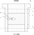
- FIG. 3 is an enlarged schematic diagram showing an enlarged part of the inner peripheral surface of the cylinder liner according to the present embodiment; It is a cross-sectional schematic diagram of a test machine of the friction test performed in the Example.
- One embodiment of the present invention is a cylinder having grooving on the inner peripheral surface of the cylinder, wherein the grooving includes a honed groove and a concave groove having a greater width and depth than the honed groove.
- the honed groove and the concave groove extend in the cylinder circumferential direction and have an inclination angle with respect to the direction perpendicular to the cylinder axial direction
- the cylinder inner peripheral surface has a crank angle of 50° or more and 140°.
- FIG. 1 is a cross-sectional view of a cylinder liner.
- the cylinder may have a structure in which a cast iron cylinder liner is cast in an aluminum alloy block, a cast iron monoblock structure, or a structure in which a cast iron dry liner or a cast iron wet liner is inserted. Although it is fine, the following description will be made in the form of using a cylinder liner.
- the cylinder liner 10 is typically a cylinder liner made of cast iron, but may be made of an aluminum alloy or a copper alloy, and its material is not particularly limited.
- the cylinder liner 10 is installed in a cylinder block of an internal combustion engine, and a piston slides inside it in the vertical direction (cylinder liner axial direction) shown in FIG.
- the combustion chamber side is "upper” in the drawing
- the crank chamber side is “lower” in the drawing.
- a dashed-dotted line 1 shown in FIG. 1 indicates the top dead center of the oil ring
- a dashed-dotted line 2 indicates the bottom dead center of the oil ring.
- the inner peripheral surface of the cylinder liner 10 of FIG. 1 has grooving, and the grooving includes honing grooves and concave grooves having a greater width and depth than the honing grooves.
- the honed groove may be a groove honed by a known method, and the number of times of honing and the shape, type, grain size, etc. of the grindstone used in honing are not particularly limited.
- a crosshatch may be formed on the inner peripheral surface of the cylinder liner by honing. When the crosshatch is formed, the angle (acute angle) is preferably 2° or more, may be 5° or more, or may be 10° or more. Also, it is usually 60° or less, may be 45° or less, may be 30° or less, or may be 15° or less.
- the concave grooves which have a larger groove width and groove depth than the honed grooves, are grooves formed by a method different from honing, such as grinding, plastic working, etching, laser processing, etc., of the cylinder liner surface. It can be formed by processing, or the like. In this embodiment, by forming grooves that can serve as oil pockets, the contact area during sliding with the piston and piston rings can be reduced, and the shear resistance of the oil can be reduced.
- the size of the concave groove is not particularly limited as long as the groove width and groove depth are larger than those of the honed groove. 50 ⁇ m or more is more preferable, 70 ⁇ m or more is still more preferable, and 100 ⁇ m or more is particularly preferable.
- the upper limit of the groove width is preferably 860 ⁇ m or less. , 800 ⁇ m or less, 500 ⁇ m or less, or 300 ⁇ m or less.
- the groove depth is usually 1.0 to 2.0 ⁇ m, may be 0.5 ⁇ m or more, may be 0.7 ⁇ m or more, may be 10.0 ⁇ m or less, and may be 9.0 ⁇ m or less. . In one example, the groove width is about 200 ⁇ m and the depth is about 1.0 ⁇ m.
- the groove widths of the honed grooves and the concave grooves can be measured, for example, by a contact-type roughness meter (SURFCORDER SE600 manufactured by Kosaka Laboratory Ltd.) at a magnification of 5000 times in the radial direction and 100 times in the axial direction. Measurement points are 3 points in the axial direction and 4 points in the circumferential direction at 90° intervals from each measurement point in the axial direction, for a total of 12 points. Let the value be the groove width. The measurement magnification may be appropriately changed according to the minimum value of the groove width to be measured.
- the measurement is performed at a magnification of 5000 times in the radial direction and 500 times in the axial direction. good too.
- a non-contact laser measuring device (for example, VK-X1000 manufactured by Keyence Corporation) may be used as a measuring device for the groove width.
- Region 3 has the grooves described above. This will be described with reference to FIG.
- FIG. 2 is an enlarged schematic view of the broken line area 4 in the central area 3 of FIG.
- the dashed line area 4 has honed grooves indicated by thin lines in the figure and recessed grooves indicated by thick lines in the figure.
- the honed groove and the recessed groove extend in the circumferential direction of the cylinder and have an inclination angle with respect to the direction perpendicular to the axial direction of the cylinder.
- the inclination angle of the honed groove is not particularly limited.
- the inclination angle of the groove is not particularly limited, but may be 2° or more, 5° or more, or 10° or more. Also, it is usually 60° or less, may be 45° or less, may be 30° or less, or may be 15° or less.
- the concave grooves are preferable because the grooves cross each other in the sliding region of the oil ring when the crank angle is 50° or more and 140° or less, so that the sliding environment becomes more uniform.
- the length 41 of 4 mm can be selected so that there are four or more concave grooves in the axial direction of the cylinder.
- the length 41 has five concave grooves.
- grooves are formed in the central region in the axial direction of the cylinder so that a length of 4 mm can be selected so that the grooves exist at four or more locations.
- the number of grooves existing in the length 41 of 4 mm is not particularly limited as long as it is 4 or more, and the length 41 of 4 mm may be selected so that there are 5 or more grooves.
- a configuration in which there are six or more concave grooves is also acceptable.
- the upper limit of the concave grooves present in a length of 4 mm is preferably 60 or less, and may be 40 or less, or even 20 or less. good.
- the concave groove is detected as being depressed toward the outer peripheral side. existence can be grasped.
- the selected length of 4 mm further satisfies at least one of the following parameters (i) to (vi).
- the mean depth W of the waviness motif of the enveloping waviness curve is 0.28 ⁇ m or more;
- (ii) (average depth W of undulation motif of enveloping undulation curve) x (average length AW of undulation motif) is 80 ⁇ m2 or more and 300 ⁇ m2 or less,
- (iii) (the level difference Rke of the core portion of the envelope waviness curve)/(the level difference Rk of the core portion of the roughness curve) is 0.6 or less;
- (iv) (average depth Rvke of protruding valleys of envelope waviness curve)/(average depth Rvk of protruding valleys of roughness curve) is 0.9 or less;
- the average depth W of (i) is preferable because the oil retention can be improved.
- the average depth W is preferably 0.4 or more, and although the upper limit is not particularly limited, it is usually 1.0 or less. Satisfying the value of W ⁇ AW in (ii) is preferable because a further friction reduction effect can be obtained.
- the value of W ⁇ AW is preferably 90 or more and preferably 270 or less. Satisfying the value of Rke/Rk in (iii) is preferable because a further friction reduction effect can be obtained.
- the value of Rke/Rk is preferably 0.5 or less, and although the lower limit is not particularly limited, it is usually 0.1 or more.
- Rvke/Rvk in (iv) Satisfying the value of Rvke/Rvk in (iv) is preferable because the shear resistance of the oil can be reduced.
- the value of Rvke/Rvk is preferably 0.7 or less, and although the lower limit is not particularly limited, it is usually 0.05 or more.
- the value of (Rpke+Rke+Rvke)/(Rpk+Rk+Rvk) in (v) is preferably 0.75 or less, and although the lower limit is not particularly limited, it is usually 0.1 or more.
- Rvke/W is preferably 0.75 or less, and although the lower limit is not particularly limited, it is usually 0.1 or more.
- Motif parameters including Rke, Rvke, Rpke, W, and AW are measured according to ISO 12085, and the average of values measured at four locations in the cylinder circumferential direction is adopted.
- the evaluation length defined by ISO is 3.2 mm, and the measurement may be made at an arbitrary 3.2 mm of the 4 mm to be measured.
- Measurement conditions for roughness parameters including Rk, Rvk, and Rpk are performed according to ISO4287, and the average of values measured at four locations in the cylinder circumferential direction is adopted.
- the evaluation length specified by ISO is 4.0 mm.
- the inner peripheral surface of the cylinder liner according to the present embodiment is not particularly limited as long as the honed grooves and the concave grooves are present in the central region 3 while satisfying specific requirements.
- the entire inner peripheral surface may be honed, or may have a coating treatment such as thermal spray coating.
- the inner peripheral surface of the cylinder is a sliding region of the oil ring when the crank angle including the top dead center is 0° or more and less than 50° (hereinafter also referred to as a top dead center region. Reference numeral 5 in FIG. 1). region.), a configuration in which the grooves are present at four or more locations in the axial direction of the cylinder and the length of 4 mm cannot be selected is preferable from the viewpoint of not significantly deteriorating oil consumption performance and friction characteristics, and the grooves are present. It is more preferable to be in a form that does not In addition, the sliding region of the oil ring when the crank angle including the bottom dead center exceeds 140° and is 180° or less (hereinafter also referred to as the bottom dead center region. In FIG.
- the region 6 it is the region 6.
- the length of 4 mm in which the grooves are present at four or more locations in the axial direction of the cylinder cannot be selected. Further, when a groove exists in the bottom dead center region, the groove prevents the generation of hydraulic pressure, which may deteriorate the friction characteristics.
- a length of 4 mm is selected so that four or more grooves are present in the oil ring sliding region when the crank angle is 80° to 110°. It is preferable from the viewpoint of obtaining a further friction reduction effect.
- the sliding area of the oil ring on the inner peripheral surface of the cylinder differs depending on the design of the engine. /4 position, and the concave groove exists in all or part of this range.
- the total length of the cylinder liner is about 194 mm, and the range of about 39 mm to 146 mm from the upper end of the cylinder liner corresponds to the sliding area of the oil ring.
- means for forming honing grooves and recessed grooves may be appropriately applied so as to satisfy the above requirements. Note that even if the cylinder block does not have a cylinder liner, the inner peripheral surface of the cylinder block can be machined in the same manner as the inner peripheral surface of the cylinder liner.
- the bore diameter of the cylinder is not particularly limited, and the concave groove shape can be applied to cylinders with various bore diameters. Further, it is preferably ⁇ 250 mm or less, more preferably ⁇ 200 mm or less.
- a cast iron material was used to prepare a cylinder liner with an inner diameter (bore diameter) of ⁇ 83 mm and a wall thickness of 1.5 mm.
- the inner peripheral surface of this cylinder liner was honed (cross hatch: acute angle of 20°) so that Rvk was 0.17 to 2.50 ⁇ m (Examples 1 to 4), 0.88 to 1.22 ⁇ m (Examples 5 to 7). ), 0.50 to 0.75 ⁇ m (Examples 8 to 9), 0.41 to 0.86 ⁇ m (Examples 10 to 13), 0.38 to 0.46 ⁇ m (Examples 14 to 16), Finished to
- Examples 1 to 16 Next, assuming that the position of the top dead center of the oil ring of the piston with the piston ring attached to the cylinder liner is 0° crank angle and the position of the bottom dead center of the oil ring is 180° crank angle, the crank angle on the inner peripheral surface of the cylinder liner is calculated. With respect to the sliding region with an angle of 80° or more and 110° or less, Examples 1, 5 to 7, and 14 to 16 are honed to a small roughness, and Examples 2 to 4 are honed to a large roughness. Nos. 8 to 13 were honed so as to have a normal roughness, and then formed concave grooves having a greater width and depth than the honed grooves.
- Examples 5 to 13 the depth of the grooves was appropriately changed, and in Examples 1 to 4 and 14 to 16, the depth of the grooves was made uniform.
- the grooves were formed at an inclination angle of 2.5° on average with respect to the direction perpendicular to the axial direction of the cylinder liner. Further, by the above processing, it is possible to select a length of 4 mm in which four or more concave grooves are present in the cylinder axial direction in the crank angle range of 80° or more and 110° or less of the cylinder liners according to Examples 1 to 16. did it.
- Comparative Examples 1 to 6 The inner peripheral surface of the cylinder liner was processed so as to have the roughness shown in Table 2 by honing the surface. Further, in Comparative Example 6, grooves having a groove width and a groove depth larger than those of the honed grooves were formed. In addition, it was not possible to select a length of 4 mm in which four or more concave grooves were present in the cylinder axial direction in any region of the surface of the cylinder liners according to Comparative Examples 1 to 6.
- a contact roughness meter (SURFCORDER SE600 manufactured by Kosaka Laboratory Co., Ltd.) It was measured at a magnification of 5000 times and 100 times in the axial direction. Measurement points are 3 points in the axial direction and 4 points in the circumferential direction at 90° intervals from each measurement point in the axial direction, for a total of 12 points. The value was taken as the groove width.
- Comparative Examples 1 to 5 which do not have a concave groove, the groove width of the honed groove was measured at a magnification of 5000 times in the radial direction and 500 times in the axial direction. Tables 1 and 2 show the results.
- the friction test and oil consumption test were performed on the cylinder liners according to Examples 1 to 16 and Comparative Examples 1 to 6 obtained above.
- ⁇ Friction test> The friction test was carried out using a single-cylinder floating liner tester (a tester that captures changes in friction between pistons and piston rings during one cycle), and was performed as an open-air motoring evaluation.
- a crank-type single-cylinder motoring tester 20 (floating liner system) with a bore diameter of 83 mm and a stroke of 86 mm was used.
- FIG. 3 shows a schematic cross-sectional view of a crank-type single-cylinder motoring tester used in the friction test.
- the cylinder liner 21 has a structure in which its movement in the radial direction is restricted by the stopper 23 and it can move only in the axial direction.
- a sensor 24 attached to the cylinder liner 21 detects the axial sliding friction force acting on the cylinder liner 21 .
- the friction mean effective pressure (FMEP) obtained by dividing the friction torque per cycle of this sliding friction force by the displacement was evaluated.
- the test conditions were a cooling water temperature of 80° C., an engine oil temperature of 80° C., an engine oil of 10W-30 (viscosity classification: SAE J300), and an evaluation rotation speed of 600 rpm to 2000 rpm.
- FMEP was classified according to the following criteria according to the relative value when the value of Comparative Example 3 (BM) was taken as 100%, and A and B were defined as acceptable levels. Tables 1 and 2 show the results. ⁇ 80% or less: A ⁇ More than 80% and 90% or less: B ⁇ More than 90% and 100% or less: C ⁇ More than 100%: D
Landscapes
- Engineering & Computer Science (AREA)
- General Engineering & Computer Science (AREA)
- Chemical & Material Sciences (AREA)
- Combustion & Propulsion (AREA)
- Mechanical Engineering (AREA)
- Cylinder Crankcases Of Internal Combustion Engines (AREA)
- Pistons, Piston Rings, And Cylinders (AREA)
Priority Applications (4)
| Application Number | Priority Date | Filing Date | Title |
|---|---|---|---|
| US18/698,909 US12577922B2 (en) | 2021-10-19 | 2022-04-25 | Cylinder |
| EP22883146.7A EP4421357A4 (en) | 2021-10-19 | 2022-04-25 | CYLINDER |
| JP2023554240A JP7813806B2 (ja) | 2021-10-19 | 2022-04-25 | シリンダ |
| KR1020247011377A KR20240055074A (ko) | 2021-10-19 | 2022-04-25 | 실린더 |
Applications Claiming Priority (2)
| Application Number | Priority Date | Filing Date | Title |
|---|---|---|---|
| JP2021-170926 | 2021-10-19 | ||
| JP2021170926 | 2021-10-19 |
Publications (1)
| Publication Number | Publication Date |
|---|---|
| WO2023067833A1 true WO2023067833A1 (ja) | 2023-04-27 |
Family
ID=82177558
Family Applications (1)
| Application Number | Title | Priority Date | Filing Date |
|---|---|---|---|
| PCT/JP2022/018684 Ceased WO2023067833A1 (ja) | 2021-10-19 | 2022-04-25 | シリンダ |
Country Status (6)
| Country | Link |
|---|---|
| US (1) | US12577922B2 (https=) |
| EP (1) | EP4421357A4 (https=) |
| JP (2) | JP7813806B2 (https=) |
| KR (1) | KR20240055074A (https=) |
| CN (2) | CN217682005U (https=) |
| WO (1) | WO2023067833A1 (https=) |
Families Citing this family (1)
| Publication number | Priority date | Publication date | Assignee | Title |
|---|---|---|---|---|
| WO2023067833A1 (ja) * | 2021-10-19 | 2023-04-27 | Tpr株式会社 | シリンダ |
Citations (5)
| Publication number | Priority date | Publication date | Assignee | Title |
|---|---|---|---|---|
| JPS5643441U (https=) * | 1979-09-11 | 1981-04-20 | ||
| JPS601504A (ja) | 1983-06-20 | 1985-01-07 | Mitsutoyo Mfg Co Ltd | テ−プの幅方向うねり量測定装置 |
| JPH04106560U (ja) | 1991-02-28 | 1992-09-14 | 帝国ピストンリング株式会社 | シリンダライナ |
| JP5513945B2 (ja) | 2009-03-31 | 2014-06-04 | 日本ピストンリング株式会社 | シリンダ |
| JP2019078267A (ja) | 2017-10-25 | 2019-05-23 | 日本ピストンリング株式会社 | 内燃機関のシリンダ及び製造方法 |
Family Cites Families (18)
| Publication number | Priority date | Publication date | Assignee | Title |
|---|---|---|---|---|
| JPS601504B2 (ja) | 1978-10-25 | 1985-01-16 | 三菱重工業株式会社 | シリンダライナ |
| JPH04106560A (ja) | 1990-08-27 | 1992-04-08 | Ricoh Co Ltd | 転写紙の位置ずれ修正装置 |
| JPH0565849A (ja) * | 1991-09-05 | 1993-03-19 | Toyota Motor Corp | 内燃機関のシリンダボア |
| DE4345042C1 (de) | 1993-12-31 | 1995-05-04 | Hebel Ag | Vorrichtung zum Entfernen der beim Schneiden von plastischen Porenbetonblöcken od. dgl. entstehenden oberen Abfallschicht |
| JP2000283291A (ja) * | 1999-03-31 | 2000-10-13 | Nippon Piston Ring Co Ltd | シリンダライナ |
| WO2009044824A1 (ja) | 2007-10-05 | 2009-04-09 | Nippon Piston Ring Co., Ltd. | シリンダ |
| KR20110071176A (ko) * | 2009-12-21 | 2011-06-29 | 두산인프라코어 주식회사 | 엔진의 실린더라이너 보어의 미세그루브 구조 |
| CN103998755B (zh) * | 2011-12-19 | 2016-07-06 | 斗山英维高株式会社 | 通过微细凹凸的最佳配置而改善了耐磨损性的气缸装置 |
| BR102013018952B1 (pt) * | 2013-07-24 | 2021-10-26 | Mahle Metal Leve S/A | Conjunto de deslizamento |
| US9169776B2 (en) * | 2014-01-09 | 2015-10-27 | Golden Lion Enterprise Co., Ltd. | Cylinder liner used for model engine |
| US9581103B1 (en) * | 2014-01-28 | 2017-02-28 | ZYNP International Corp. | Cylinder liner and method of forming the same |
| BR102015031391A2 (pt) * | 2015-12-15 | 2017-06-20 | Mahle Int Gmbh | Cylinder shirt for an internal combustion engine |
| KR20180028159A (ko) * | 2016-09-08 | 2018-03-16 | 현대자동차주식회사 | 전단저항 감소 패턴을 갖는 엔진 |
| CN109844292B (zh) | 2016-10-20 | 2021-12-07 | 本田技研工业株式会社 | 具有滑动接触表面的构件 |
| JP6533858B1 (ja) * | 2018-07-26 | 2019-06-19 | Tpr株式会社 | 鋳鉄製シリンダライナおよび内燃機関 |
| JP7297917B2 (ja) * | 2019-11-06 | 2023-06-26 | Tpr株式会社 | シリンダライナ及びシリンダボア |
| US11536218B1 (en) * | 2021-10-14 | 2022-12-27 | Caterpillar Inc. | Method and system for a cylinder liner |
| WO2023067833A1 (ja) * | 2021-10-19 | 2023-04-27 | Tpr株式会社 | シリンダ |
-
2022
- 2022-04-25 WO PCT/JP2022/018684 patent/WO2023067833A1/ja not_active Ceased
- 2022-04-25 KR KR1020247011377A patent/KR20240055074A/ko active Pending
- 2022-04-25 JP JP2023554240A patent/JP7813806B2/ja active Active
- 2022-04-25 US US18/698,909 patent/US12577922B2/en active Active
- 2022-04-25 EP EP22883146.7A patent/EP4421357A4/en active Pending
- 2022-04-29 CN CN202221033865.4U patent/CN217682005U/zh active Active
- 2022-04-29 CN CN202210475924.1A patent/CN114704406A/zh active Pending
- 2022-08-16 JP JP2022129585A patent/JP7369253B2/ja active Active
Patent Citations (5)
| Publication number | Priority date | Publication date | Assignee | Title |
|---|---|---|---|---|
| JPS5643441U (https=) * | 1979-09-11 | 1981-04-20 | ||
| JPS601504A (ja) | 1983-06-20 | 1985-01-07 | Mitsutoyo Mfg Co Ltd | テ−プの幅方向うねり量測定装置 |
| JPH04106560U (ja) | 1991-02-28 | 1992-09-14 | 帝国ピストンリング株式会社 | シリンダライナ |
| JP5513945B2 (ja) | 2009-03-31 | 2014-06-04 | 日本ピストンリング株式会社 | シリンダ |
| JP2019078267A (ja) | 2017-10-25 | 2019-05-23 | 日本ピストンリング株式会社 | 内燃機関のシリンダ及び製造方法 |
Non-Patent Citations (1)
| Title |
|---|
| See also references of EP4421357A4 |
Also Published As
| Publication number | Publication date |
|---|---|
| KR20240055074A (ko) | 2024-04-26 |
| JP7369253B2 (ja) | 2023-10-25 |
| EP4421357A1 (en) | 2024-08-28 |
| CN217682005U (zh) | 2022-10-28 |
| JP7813806B2 (ja) | 2026-02-13 |
| JP2023061357A (ja) | 2023-05-01 |
| JPWO2023067833A1 (https=) | 2023-04-27 |
| US12577922B2 (en) | 2026-03-17 |
| CN114704406A (zh) | 2022-07-05 |
| EP4421357A4 (en) | 2025-02-26 |
| US20250320843A1 (en) | 2025-10-16 |
Similar Documents
| Publication | Publication Date | Title |
|---|---|---|
| CN103998755B (zh) | 通过微细凹凸的最佳配置而改善了耐磨损性的气缸装置 | |
| JP7297917B2 (ja) | シリンダライナ及びシリンダボア | |
| EP3181292A1 (en) | Cylinder liner for an internal combustion engine | |
| GB2431976A (en) | I.c. engine cylinder bore wall with pockets for retaining lubricant | |
| JP7329690B2 (ja) | シリンダライナ及びシリンダボア | |
| JP7369253B2 (ja) | シリンダ | |
| JP7662568B2 (ja) | 内燃機関の摺動構造 | |
| JP7593932B2 (ja) | 内燃機関の摺動構造 | |
| JP6894879B2 (ja) | 内燃機関のシリンダ及び製造方法 | |
| JP7264822B2 (ja) | 対向ピストンエンジンのシリンダボア表面構造 | |
| US4829955A (en) | Piston cylinder kit for internal combustion engines | |
| JP7045383B2 (ja) | ピストンリング | |
| JP2008231972A (ja) | エンジンのピストン | |
| JP6914291B2 (ja) | 内燃機関のシリンダ | |
| CN105221284B (zh) | 内燃机缸套 | |
| JPS6045745B2 (ja) | シリンダ | |
| KR20130070399A (ko) | 최적의 미세요철 배치 및 표면 거칠기를 갖는 실린더 장치 |
Legal Events
| Date | Code | Title | Description |
|---|---|---|---|
| 121 | Ep: the epo has been informed by wipo that ep was designated in this application |
Ref document number: 22883146 Country of ref document: EP Kind code of ref document: A1 |
|
| WWE | Wipo information: entry into national phase |
Ref document number: 2023554240 Country of ref document: JP |
|
| ENP | Entry into the national phase |
Ref document number: 20247011377 Country of ref document: KR Kind code of ref document: A |
|
| WWE | Wipo information: entry into national phase |
Ref document number: 202447037755 Country of ref document: IN |
|
| WWE | Wipo information: entry into national phase |
Ref document number: 2022883146 Country of ref document: EP |
|
| NENP | Non-entry into the national phase |
Ref country code: DE |
|
| ENP | Entry into the national phase |
Ref document number: 2022883146 Country of ref document: EP Effective date: 20240521 |
|
| WWP | Wipo information: published in national office |
Ref document number: 18698909 Country of ref document: US |