WO2023067833A1 - Cylinder - Google Patents
Cylinder Download PDFInfo
- Publication number
- WO2023067833A1 WO2023067833A1 PCT/JP2022/018684 JP2022018684W WO2023067833A1 WO 2023067833 A1 WO2023067833 A1 WO 2023067833A1 JP 2022018684 W JP2022018684 W JP 2022018684W WO 2023067833 A1 WO2023067833 A1 WO 2023067833A1
- Authority
- WO
- WIPO (PCT)
- Prior art keywords
- cylinder
- groove
- less
- grooves
- curve
- Prior art date
Links
- 230000002093 peripheral effect Effects 0.000 claims description 33
- 239000003921 oil Substances 0.000 description 36
- 238000012360 testing method Methods 0.000 description 12
- 229910001018 Cast iron Inorganic materials 0.000 description 11
- 230000000694 effects Effects 0.000 description 9
- 230000000052 comparative effect Effects 0.000 description 8
- 238000005259 measurement Methods 0.000 description 8
- 238000012545 processing Methods 0.000 description 7
- 238000002485 combustion reaction Methods 0.000 description 6
- 238000000034 method Methods 0.000 description 5
- 229910000838 Al alloy Inorganic materials 0.000 description 4
- 230000002542 deteriorative effect Effects 0.000 description 4
- 238000011156 evaluation Methods 0.000 description 4
- 238000010586 diagram Methods 0.000 description 3
- 230000003746 surface roughness Effects 0.000 description 3
- 230000001154 acute effect Effects 0.000 description 2
- 239000000463 material Substances 0.000 description 2
- 239000010705 motor oil Substances 0.000 description 2
- 229910000881 Cu alloy Inorganic materials 0.000 description 1
- 230000015572 biosynthetic process Effects 0.000 description 1
- 239000011248 coating agent Substances 0.000 description 1
- 238000000576 coating method Methods 0.000 description 1
- 239000000498 cooling water Substances 0.000 description 1
- 230000000994 depressogenic effect Effects 0.000 description 1
- 238000013461 design Methods 0.000 description 1
- 238000006073 displacement reaction Methods 0.000 description 1
- 238000005530 etching Methods 0.000 description 1
- 239000002803 fossil fuel Substances 0.000 description 1
- 239000000446 fuel Substances 0.000 description 1
- 239000011521 glass Substances 0.000 description 1
- 238000000227 grinding Methods 0.000 description 1
- 230000001050 lubricating effect Effects 0.000 description 1
- 238000005461 lubrication Methods 0.000 description 1
- 230000014759 maintenance of location Effects 0.000 description 1
- 238000004519 manufacturing process Methods 0.000 description 1
- 238000007747 plating Methods 0.000 description 1
- 238000005070 sampling Methods 0.000 description 1
- 238000005507 spraying Methods 0.000 description 1
- 238000007751 thermal spraying Methods 0.000 description 1
Images


Classifications
-
- F—MECHANICAL ENGINEERING; LIGHTING; HEATING; WEAPONS; BLASTING
- F02—COMBUSTION ENGINES; HOT-GAS OR COMBUSTION-PRODUCT ENGINE PLANTS
- F02F—CYLINDERS, PISTONS OR CASINGS, FOR COMBUSTION ENGINES; ARRANGEMENTS OF SEALINGS IN COMBUSTION ENGINES
- F02F1/00—Cylinders; Cylinder heads
- F02F1/18—Other cylinders
-
- F—MECHANICAL ENGINEERING; LIGHTING; HEATING; WEAPONS; BLASTING
- F02—COMBUSTION ENGINES; HOT-GAS OR COMBUSTION-PRODUCT ENGINE PLANTS
- F02F—CYLINDERS, PISTONS OR CASINGS, FOR COMBUSTION ENGINES; ARRANGEMENTS OF SEALINGS IN COMBUSTION ENGINES
- F02F1/00—Cylinders; Cylinder heads
-
- F—MECHANICAL ENGINEERING; LIGHTING; HEATING; WEAPONS; BLASTING
- F02—COMBUSTION ENGINES; HOT-GAS OR COMBUSTION-PRODUCT ENGINE PLANTS
- F02F—CYLINDERS, PISTONS OR CASINGS, FOR COMBUSTION ENGINES; ARRANGEMENTS OF SEALINGS IN COMBUSTION ENGINES
- F02F1/00—Cylinders; Cylinder heads
- F02F1/18—Other cylinders
- F02F1/20—Other cylinders characterised by constructional features providing for lubrication
-
- F—MECHANICAL ENGINEERING; LIGHTING; HEATING; WEAPONS; BLASTING
- F16—ENGINEERING ELEMENTS AND UNITS; GENERAL MEASURES FOR PRODUCING AND MAINTAINING EFFECTIVE FUNCTIONING OF MACHINES OR INSTALLATIONS; THERMAL INSULATION IN GENERAL
- F16J—PISTONS; CYLINDERS; SEALINGS
- F16J10/00—Engine or like cylinders; Features of hollow, e.g. cylindrical, bodies in general
- F16J10/02—Cylinders designed to receive moving pistons or plungers
- F16J10/04—Running faces; Liners
Definitions
- the present invention relates to cylinders used in internal combustion engines.
- Cylinders of internal combustion engines are mainly made of cast iron for their inner peripheral surfaces.
- a structure in which a cast iron cylinder liner is cast in an aluminum alloy block a cast iron monoblock structure, a structure in which a cast iron dry liner or a cast iron wet liner is inserted.
- Both of these structures are required to reduce CO 2 emissions and fossil fuel consumption, and therefore, friction reduction techniques by controlling the roughness of the inner peripheral surface of the cylinder and structural control are being studied.
- Patent Document 1 as a cylinder of an internal combustion engine capable of reducing the frictional mean effective pressure without performing complicated processing, the inner wall surface is defined into an upper region, a lower region, and a stroke center region. , a cylinder in which the surface roughness of the mid-stroke region is greater than the surface roughness of the upper and lower regions.
- Patent Literature 2 discloses that the inner peripheral surface of the cylinder liner that has been honed has undulations in the axial direction, thereby maintaining a good lubricating state between the piston and the cylinder liner.
- the piston ring sliding surface of the cylinder liner is formed with a wavy uneven surface along the sliding direction of the piston ring, and the wavy surface is formed in the vicinity of the central portion of the sliding stroke of the first piston ring.
- the deepest formation is disclosed to improve the lubrication performance of the cylinder liner.
- a recess is formed in the stroke central region of the inner wall surface of the cylinder, and the total area of all the recesses is 1 to 80% of the area of the stroke central region, and the area other than the stroke central region discloses that reciprocating friction between a piston ring and a cylinder inner wall surface is reduced by forming an inner wall surface without a concave portion.
- JP 2019-78267 A Japanese Utility Model Laid-Open No. 4-106560 Japanese Patent Publication No. 60-001504 Japanese Patent No. 5513945
- Patent Document 1 states that in the stroke center region where the sliding speed between the inner wall surface of the cylinder liner and the piston ring is high, the influence of the shear resistance of the oil on the friction loss increases. Friction loss in an internal combustion engine is significant near the center of the stroke where the amount of work is large. Therefore, reducing the friction near the center of the stroke without deteriorating the oil consumption performance is effective in reducing CO2 emissions. It is proposed to However, with the surface roughness of the plateau surface formed by plateau processing after honing with the grindstone adjusted, the effect of reducing friction is not sufficiently obtained, and there is room for improvement.
- An object of the present invention is to provide a cylinder capable of obtaining a higher friction reduction effect by a method different from those already proposed.
- the inventors of the present invention have conducted studies to solve the above-mentioned problems, and have formed a recessed groove having a honed groove and a groove width and a groove depth larger than those of the honed groove in the stroke center region of the inner peripheral surface of the cylinder.
- the inventors have found that a high friction reduction effect can be obtained by surface processing so as to have a certain number or more, and have completed the present invention.
- the present invention provides a cylinder having grooves on the inner peripheral surface of the cylinder,
- the grooving includes a honed groove and a concave groove having a greater groove width and groove depth than the honed groove,
- the honed groove and the recessed groove extend in the cylinder circumferential direction and have an inclination angle with respect to a direction perpendicular to the cylinder axial direction,
- the inner peripheral surface of the cylinder can be selected to have a length of 4 mm in which the concave grooves are present at four or more locations in the sliding region of the oil ring when the crank angle is 50° or more and 140° or less. , is the cylinder.
- the honed groove and the recessed groove have a portion where the recessed grooves cross each other in the sliding region of the oil ring when the crank angle is 50° or more and 140° or less. Further, it is preferable that the concave groove has a groove width of 30 ⁇ m or more.
- the mean depth W of the waviness motif of the enveloping waviness curve is 0.28 ⁇ m or more;
- (ii) (average depth W of undulation motif of enveloping undulation curve) x (average length AW of undulation motif) is 80 ⁇ m2 or more and 300 ⁇ m2 or less,
- (iii) (the level difference Rke of the core portion of the envelope waviness curve)/(the level difference Rk of the core portion of the roughness curve) is 0.6 or less;
- (iv) (average depth Rvke of protruding valleys of envelope waviness curve)/(average depth Rvk of protruding valleys of roughness curve) is 0.9 or less;
- the inner peripheral surface of the cylinder is 4 mm in which the concave grooves are present at four or more locations in the sliding region of the oil ring when the crank angle including the top dead center is 0° or more and less than 50°.
- a form in which the length of is not selectable is preferred.
- the friction on the sliding surface is reduced from the conventional level, improving fuel efficiency without significantly deteriorating the oil consumption performance.
- a cylinder that can As a preferred form, by reducing the number of concave grooves or by eliminating the concave grooves in the vicinity of the top dead center, it is possible to achieve compatibility with oil consumption performance.
- FIG. 3 is an enlarged schematic diagram showing an enlarged part of the inner peripheral surface of the cylinder liner according to the present embodiment; It is a cross-sectional schematic diagram of a test machine of the friction test performed in the Example.
- One embodiment of the present invention is a cylinder having grooving on the inner peripheral surface of the cylinder, wherein the grooving includes a honed groove and a concave groove having a greater width and depth than the honed groove.
- the honed groove and the concave groove extend in the cylinder circumferential direction and have an inclination angle with respect to the direction perpendicular to the cylinder axial direction
- the cylinder inner peripheral surface has a crank angle of 50° or more and 140°.
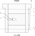
- FIG. 1 is a cross-sectional view of a cylinder liner.
- the cylinder may have a structure in which a cast iron cylinder liner is cast in an aluminum alloy block, a cast iron monoblock structure, or a structure in which a cast iron dry liner or a cast iron wet liner is inserted. Although it is fine, the following description will be made in the form of using a cylinder liner.
- the cylinder liner 10 is typically a cylinder liner made of cast iron, but may be made of an aluminum alloy or a copper alloy, and its material is not particularly limited.
- the cylinder liner 10 is installed in a cylinder block of an internal combustion engine, and a piston slides inside it in the vertical direction (cylinder liner axial direction) shown in FIG.
- the combustion chamber side is "upper” in the drawing
- the crank chamber side is “lower” in the drawing.
- a dashed-dotted line 1 shown in FIG. 1 indicates the top dead center of the oil ring
- a dashed-dotted line 2 indicates the bottom dead center of the oil ring.
- the inner peripheral surface of the cylinder liner 10 of FIG. 1 has grooving, and the grooving includes honing grooves and concave grooves having a greater width and depth than the honing grooves.
- the honed groove may be a groove honed by a known method, and the number of times of honing and the shape, type, grain size, etc. of the grindstone used in honing are not particularly limited.
- a crosshatch may be formed on the inner peripheral surface of the cylinder liner by honing. When the crosshatch is formed, the angle (acute angle) is preferably 2° or more, may be 5° or more, or may be 10° or more. Also, it is usually 60° or less, may be 45° or less, may be 30° or less, or may be 15° or less.
- the concave grooves which have a larger groove width and groove depth than the honed grooves, are grooves formed by a method different from honing, such as grinding, plastic working, etching, laser processing, etc., of the cylinder liner surface. It can be formed by processing, or the like. In this embodiment, by forming grooves that can serve as oil pockets, the contact area during sliding with the piston and piston rings can be reduced, and the shear resistance of the oil can be reduced.
- the size of the concave groove is not particularly limited as long as the groove width and groove depth are larger than those of the honed groove. 50 ⁇ m or more is more preferable, 70 ⁇ m or more is still more preferable, and 100 ⁇ m or more is particularly preferable.
- the upper limit of the groove width is preferably 860 ⁇ m or less. , 800 ⁇ m or less, 500 ⁇ m or less, or 300 ⁇ m or less.
- the groove depth is usually 1.0 to 2.0 ⁇ m, may be 0.5 ⁇ m or more, may be 0.7 ⁇ m or more, may be 10.0 ⁇ m or less, and may be 9.0 ⁇ m or less. . In one example, the groove width is about 200 ⁇ m and the depth is about 1.0 ⁇ m.
- the groove widths of the honed grooves and the concave grooves can be measured, for example, by a contact-type roughness meter (SURFCORDER SE600 manufactured by Kosaka Laboratory Ltd.) at a magnification of 5000 times in the radial direction and 100 times in the axial direction. Measurement points are 3 points in the axial direction and 4 points in the circumferential direction at 90° intervals from each measurement point in the axial direction, for a total of 12 points. Let the value be the groove width. The measurement magnification may be appropriately changed according to the minimum value of the groove width to be measured.
- the measurement is performed at a magnification of 5000 times in the radial direction and 500 times in the axial direction. good too.
- a non-contact laser measuring device (for example, VK-X1000 manufactured by Keyence Corporation) may be used as a measuring device for the groove width.
- Region 3 has the grooves described above. This will be described with reference to FIG.
- FIG. 2 is an enlarged schematic view of the broken line area 4 in the central area 3 of FIG.
- the dashed line area 4 has honed grooves indicated by thin lines in the figure and recessed grooves indicated by thick lines in the figure.
- the honed groove and the recessed groove extend in the circumferential direction of the cylinder and have an inclination angle with respect to the direction perpendicular to the axial direction of the cylinder.
- the inclination angle of the honed groove is not particularly limited.
- the inclination angle of the groove is not particularly limited, but may be 2° or more, 5° or more, or 10° or more. Also, it is usually 60° or less, may be 45° or less, may be 30° or less, or may be 15° or less.
- the concave grooves are preferable because the grooves cross each other in the sliding region of the oil ring when the crank angle is 50° or more and 140° or less, so that the sliding environment becomes more uniform.
- the length 41 of 4 mm can be selected so that there are four or more concave grooves in the axial direction of the cylinder.
- the length 41 has five concave grooves.
- grooves are formed in the central region in the axial direction of the cylinder so that a length of 4 mm can be selected so that the grooves exist at four or more locations.
- the number of grooves existing in the length 41 of 4 mm is not particularly limited as long as it is 4 or more, and the length 41 of 4 mm may be selected so that there are 5 or more grooves.
- a configuration in which there are six or more concave grooves is also acceptable.
- the upper limit of the concave grooves present in a length of 4 mm is preferably 60 or less, and may be 40 or less, or even 20 or less. good.
- the concave groove is detected as being depressed toward the outer peripheral side. existence can be grasped.
- the selected length of 4 mm further satisfies at least one of the following parameters (i) to (vi).
- the mean depth W of the waviness motif of the enveloping waviness curve is 0.28 ⁇ m or more;
- (ii) (average depth W of undulation motif of enveloping undulation curve) x (average length AW of undulation motif) is 80 ⁇ m2 or more and 300 ⁇ m2 or less,
- (iii) (the level difference Rke of the core portion of the envelope waviness curve)/(the level difference Rk of the core portion of the roughness curve) is 0.6 or less;
- (iv) (average depth Rvke of protruding valleys of envelope waviness curve)/(average depth Rvk of protruding valleys of roughness curve) is 0.9 or less;
- the average depth W of (i) is preferable because the oil retention can be improved.
- the average depth W is preferably 0.4 or more, and although the upper limit is not particularly limited, it is usually 1.0 or less. Satisfying the value of W ⁇ AW in (ii) is preferable because a further friction reduction effect can be obtained.
- the value of W ⁇ AW is preferably 90 or more and preferably 270 or less. Satisfying the value of Rke/Rk in (iii) is preferable because a further friction reduction effect can be obtained.
- the value of Rke/Rk is preferably 0.5 or less, and although the lower limit is not particularly limited, it is usually 0.1 or more.
- Rvke/Rvk in (iv) Satisfying the value of Rvke/Rvk in (iv) is preferable because the shear resistance of the oil can be reduced.
- the value of Rvke/Rvk is preferably 0.7 or less, and although the lower limit is not particularly limited, it is usually 0.05 or more.
- the value of (Rpke+Rke+Rvke)/(Rpk+Rk+Rvk) in (v) is preferably 0.75 or less, and although the lower limit is not particularly limited, it is usually 0.1 or more.
- Rvke/W is preferably 0.75 or less, and although the lower limit is not particularly limited, it is usually 0.1 or more.
- Motif parameters including Rke, Rvke, Rpke, W, and AW are measured according to ISO 12085, and the average of values measured at four locations in the cylinder circumferential direction is adopted.
- the evaluation length defined by ISO is 3.2 mm, and the measurement may be made at an arbitrary 3.2 mm of the 4 mm to be measured.
- Measurement conditions for roughness parameters including Rk, Rvk, and Rpk are performed according to ISO4287, and the average of values measured at four locations in the cylinder circumferential direction is adopted.
- the evaluation length specified by ISO is 4.0 mm.
- the inner peripheral surface of the cylinder liner according to the present embodiment is not particularly limited as long as the honed grooves and the concave grooves are present in the central region 3 while satisfying specific requirements.
- the entire inner peripheral surface may be honed, or may have a coating treatment such as thermal spray coating.
- the inner peripheral surface of the cylinder is a sliding region of the oil ring when the crank angle including the top dead center is 0° or more and less than 50° (hereinafter also referred to as a top dead center region. Reference numeral 5 in FIG. 1). region.), a configuration in which the grooves are present at four or more locations in the axial direction of the cylinder and the length of 4 mm cannot be selected is preferable from the viewpoint of not significantly deteriorating oil consumption performance and friction characteristics, and the grooves are present. It is more preferable to be in a form that does not In addition, the sliding region of the oil ring when the crank angle including the bottom dead center exceeds 140° and is 180° or less (hereinafter also referred to as the bottom dead center region. In FIG.
- the region 6 it is the region 6.
- the length of 4 mm in which the grooves are present at four or more locations in the axial direction of the cylinder cannot be selected. Further, when a groove exists in the bottom dead center region, the groove prevents the generation of hydraulic pressure, which may deteriorate the friction characteristics.
- a length of 4 mm is selected so that four or more grooves are present in the oil ring sliding region when the crank angle is 80° to 110°. It is preferable from the viewpoint of obtaining a further friction reduction effect.
- the sliding area of the oil ring on the inner peripheral surface of the cylinder differs depending on the design of the engine. /4 position, and the concave groove exists in all or part of this range.
- the total length of the cylinder liner is about 194 mm, and the range of about 39 mm to 146 mm from the upper end of the cylinder liner corresponds to the sliding area of the oil ring.
- means for forming honing grooves and recessed grooves may be appropriately applied so as to satisfy the above requirements. Note that even if the cylinder block does not have a cylinder liner, the inner peripheral surface of the cylinder block can be machined in the same manner as the inner peripheral surface of the cylinder liner.
- the bore diameter of the cylinder is not particularly limited, and the concave groove shape can be applied to cylinders with various bore diameters. Further, it is preferably ⁇ 250 mm or less, more preferably ⁇ 200 mm or less.
- a cast iron material was used to prepare a cylinder liner with an inner diameter (bore diameter) of ⁇ 83 mm and a wall thickness of 1.5 mm.
- the inner peripheral surface of this cylinder liner was honed (cross hatch: acute angle of 20°) so that Rvk was 0.17 to 2.50 ⁇ m (Examples 1 to 4), 0.88 to 1.22 ⁇ m (Examples 5 to 7). ), 0.50 to 0.75 ⁇ m (Examples 8 to 9), 0.41 to 0.86 ⁇ m (Examples 10 to 13), 0.38 to 0.46 ⁇ m (Examples 14 to 16), Finished to
- Examples 1 to 16 Next, assuming that the position of the top dead center of the oil ring of the piston with the piston ring attached to the cylinder liner is 0° crank angle and the position of the bottom dead center of the oil ring is 180° crank angle, the crank angle on the inner peripheral surface of the cylinder liner is calculated. With respect to the sliding region with an angle of 80° or more and 110° or less, Examples 1, 5 to 7, and 14 to 16 are honed to a small roughness, and Examples 2 to 4 are honed to a large roughness. Nos. 8 to 13 were honed so as to have a normal roughness, and then formed concave grooves having a greater width and depth than the honed grooves.
- Examples 5 to 13 the depth of the grooves was appropriately changed, and in Examples 1 to 4 and 14 to 16, the depth of the grooves was made uniform.
- the grooves were formed at an inclination angle of 2.5° on average with respect to the direction perpendicular to the axial direction of the cylinder liner. Further, by the above processing, it is possible to select a length of 4 mm in which four or more concave grooves are present in the cylinder axial direction in the crank angle range of 80° or more and 110° or less of the cylinder liners according to Examples 1 to 16. did it.
- Comparative Examples 1 to 6 The inner peripheral surface of the cylinder liner was processed so as to have the roughness shown in Table 2 by honing the surface. Further, in Comparative Example 6, grooves having a groove width and a groove depth larger than those of the honed grooves were formed. In addition, it was not possible to select a length of 4 mm in which four or more concave grooves were present in the cylinder axial direction in any region of the surface of the cylinder liners according to Comparative Examples 1 to 6.
- a contact roughness meter (SURFCORDER SE600 manufactured by Kosaka Laboratory Co., Ltd.) It was measured at a magnification of 5000 times and 100 times in the axial direction. Measurement points are 3 points in the axial direction and 4 points in the circumferential direction at 90° intervals from each measurement point in the axial direction, for a total of 12 points. The value was taken as the groove width.
- Comparative Examples 1 to 5 which do not have a concave groove, the groove width of the honed groove was measured at a magnification of 5000 times in the radial direction and 500 times in the axial direction. Tables 1 and 2 show the results.
- the friction test and oil consumption test were performed on the cylinder liners according to Examples 1 to 16 and Comparative Examples 1 to 6 obtained above.
- ⁇ Friction test> The friction test was carried out using a single-cylinder floating liner tester (a tester that captures changes in friction between pistons and piston rings during one cycle), and was performed as an open-air motoring evaluation.
- a crank-type single-cylinder motoring tester 20 (floating liner system) with a bore diameter of 83 mm and a stroke of 86 mm was used.
- FIG. 3 shows a schematic cross-sectional view of a crank-type single-cylinder motoring tester used in the friction test.
- the cylinder liner 21 has a structure in which its movement in the radial direction is restricted by the stopper 23 and it can move only in the axial direction.
- a sensor 24 attached to the cylinder liner 21 detects the axial sliding friction force acting on the cylinder liner 21 .
- the friction mean effective pressure (FMEP) obtained by dividing the friction torque per cycle of this sliding friction force by the displacement was evaluated.
- the test conditions were a cooling water temperature of 80° C., an engine oil temperature of 80° C., an engine oil of 10W-30 (viscosity classification: SAE J300), and an evaluation rotation speed of 600 rpm to 2000 rpm.
- FMEP was classified according to the following criteria according to the relative value when the value of Comparative Example 3 (BM) was taken as 100%, and A and B were defined as acceptable levels. Tables 1 and 2 show the results. ⁇ 80% or less: A ⁇ More than 80% and 90% or less: B ⁇ More than 90% and 100% or less: C ⁇ More than 100%: D
Landscapes
- Engineering & Computer Science (AREA)
- General Engineering & Computer Science (AREA)
- Chemical & Material Sciences (AREA)
- Combustion & Propulsion (AREA)
- Mechanical Engineering (AREA)
- Pistons, Piston Rings, And Cylinders (AREA)
- Cylinder Crankcases Of Internal Combustion Engines (AREA)
Abstract
Description
一方で、シリンダの内周面に耐摩耗性に優れる溶射やめっき等のコーティングが施されたものや、アルミ合金の直摺動とするものも存在する。 Cylinders of internal combustion engines are mainly made of cast iron for their inner peripheral surfaces. For example, a structure in which a cast iron cylinder liner is cast in an aluminum alloy block, a cast iron monoblock structure, a structure in which a cast iron dry liner or a cast iron wet liner is inserted.
On the other hand, there are cylinders in which the inner peripheral surface of the cylinder is coated with thermal spraying, plating, or the like, which has excellent wear resistance, and cylinders in which an aluminum alloy is directly slidable.
特許文献2にはホーニング加工されたシリンダライナの内周表面において、軸方向にうねりを有することで、ピストンとシリンダライナ間の潤滑状態が良好に維持されることが開示されている。
また特許文献3には、シリンダライナのピストンリング摺動面に、該ピストンリングの摺動方向に沿って波状の凹凸面で形成され、第1ピストンリングの摺動行程の中央部近傍においてウェーブを最も深く形成することで、シリンダライナの潤滑性能を改善させることが開示されている。
更に特許文献4には、シリンダ内壁面のうち行程中央部領域に凹部が形成され、行程中央部領域の面積のうち全凹部の面積の合計を1~80%とし、行程中央部領域以外の領域には凹部が形成されていない内壁面とすることで、ピストンリングとシリンダ内壁面との往復動摩擦を低減させることが開示されている。 For example, in
Further, in
Furthermore, in
また、上記特許文献2のように、シリンダの内周表面に単にうねりが存在し、軸方向にうねりピッチが10~20mmであり、うねり深さが1~5μmでは、ピストンリングの挙動に影響を及ぼす可能があり、摩擦低減の効果が十分に得られず、改善の余地があった。
また、上記特許文献3のように、シリンダライナの内面のウェーブ深さが0.005~0.1mmでは、オイル消費性能と摩擦特性が悪化する虞があった。
更に、上記特許文献4のように、複数個形成された凹部の面の最大高さRyが0.1μm以上30μm以下では、摩擦低減の効果が十分に得られず、改善の余地があった。
本発明では、既に提案されたものとは異なる方法で、より高い摩擦低減効果を得ることができるシリンダを提供することを課題とする。 The
In addition, as in
In addition, as in
Furthermore, as in
SUMMARY OF THE INVENTION An object of the present invention is to provide a cylinder capable of obtaining a higher friction reduction effect by a method different from those already proposed.
前記溝加工は、ホーニング加工溝、及び該ホーニング加工溝よりも溝幅及び溝深さが大きい凹溝を含み、
前記ホーニング加工溝及び前記凹溝はシリンダ周方向に延在し、且つシリンダ軸方向と垂直な方向に対して傾斜角を有し、
前記シリンダ内周面は、クランク角が50°以上140°以下である時のオイルリングの摺動領域において、シリンダ軸方向に、前記凹溝が4カ所以上存在する4mmの長さを選択し得る、シリンダである。 The present invention provides a cylinder having grooves on the inner peripheral surface of the cylinder,
The grooving includes a honed groove and a concave groove having a greater groove width and groove depth than the honed groove,
The honed groove and the recessed groove extend in the cylinder circumferential direction and have an inclination angle with respect to a direction perpendicular to the cylinder axial direction,
The inner peripheral surface of the cylinder can be selected to have a length of 4 mm in which the concave grooves are present at four or more locations in the sliding region of the oil ring when the crank angle is 50° or more and 140° or less. , is the cylinder.
また、前記凹溝は、溝幅が30μm以上であることが好ましい。 It is preferable that the honed groove and the recessed groove have a portion where the recessed grooves cross each other in the sliding region of the oil ring when the crank angle is 50° or more and 140° or less.
Further, it is preferable that the concave groove has a groove width of 30 μm or more.
(i)包絡うねり曲線のうねりモチーフの平均深さWが0.28μm以上である、
(ii)(包絡うねり曲線のうねりモチーフの平均深さW)×(うねりモチーフの平均長さAW)が80μm2以上300μm2以下である、
(iii)(包絡うねり曲線のコア部のレベル差Rke)/(粗さ曲線のコア部のレベル差Rk)が0.6以下である、
(iv)(包絡うねり曲線の突出谷部の平均深さRvke)/(粗さ曲線の突出谷部の平均深さRvk)が0.9以下である、
(v)(包絡うねり曲線の、突出山部の平均高さRpke+コア部のレベル差Rke+突出谷部の平均深さRvke)/(粗さ曲線の、突出山部の平均高さRpk+コア部のレベル差Rk+突出谷部の平均深さRvk)が0.9以下である、
(vi)(包絡うねり曲線の突出谷部の平均深さRvke)/(包絡うねり曲線のうねりモチーフの平均深さW)が1.0以下である。 Further, it is preferable that at least one of the following parameters (i) to (vi) is satisfied in the selected length of 4 mm.
(i) the mean depth W of the waviness motif of the enveloping waviness curve is 0.28 μm or more;
(ii) (average depth W of undulation motif of enveloping undulation curve) x (average length AW of undulation motif) is 80 µm2 or more and 300 µm2 or less,
(iii) (the level difference Rke of the core portion of the envelope waviness curve)/(the level difference Rk of the core portion of the roughness curve) is 0.6 or less;
(iv) (average depth Rvke of protruding valleys of envelope waviness curve)/(average depth Rvk of protruding valleys of roughness curve) is 0.9 or less;
(v) (Envelope waviness curve average height Rpke of protruding peak + level difference Rke of core + average depth Rvke of protruding valley) / (Roughness curve average height Rpk of protruding peak + core) Level difference Rk + average depth of protruding valley Rvk) is 0.9 or less,
(vi) (Average depth Rvke of protruding troughs of enveloping waviness curve)/(Average depth W of waviness motifs of enveloping waviness curve) is 1.0 or less.
シリンダライナ10は、典型的には鋳鉄製のシリンダライナであるが、アルミニウム合金や銅合金により形成されてもよく、その材質は特段限定されない。 FIG. 1 is a cross-sectional view of a cylinder liner. The cylinder may have a structure in which a cast iron cylinder liner is cast in an aluminum alloy block, a cast iron monoblock structure, or a structure in which a cast iron dry liner or a cast iron wet liner is inserted. Although it is fine, the following description will be made in the form of using a cylinder liner.
The
図1に記載の一点鎖線1はオイルリングの上死点を、一点鎖線2はオイルリングの下死点を示す。 The
A dashed-dotted
ホーニング加工溝は、既知の方法によりホーニングされた加工溝であってよく、ホーニング加工の回数や、ホーニング加工で用いる砥石の形状、種類、粒度等は特に限定されない。また、ホーニング加工によりシリンダライナの内周面にクロスハッチが形成されてもよい。クロスハッチを形成する場合、その角度(鋭角)は2°以上が好ましく、5°以上であってよく、10°以上であってよい。また通常60°以下であり、45°以下であってよく、30°以下であってよく、15°以下であってよい。 The inner peripheral surface of the
The honed groove may be a groove honed by a known method, and the number of times of honing and the shape, type, grain size, etc. of the grindstone used in honing are not particularly limited. Further, a crosshatch may be formed on the inner peripheral surface of the cylinder liner by honing. When the crosshatch is formed, the angle (acute angle) is preferably 2° or more, may be 5° or more, or may be 10° or more. Also, it is usually 60° or less, may be 45° or less, may be 30° or less, or may be 15° or less.
凹溝は、ホーニング加工溝よりも溝幅及び溝深さが大きい限り、特にその大きさは限定されないが、オイルのせん断抵抗低減効果を得る観点から、溝幅の下限は、30μm以上が好ましく、50μm以上がより好ましく、70μm以上が更に好ましく、100μm以上が特に好ましい。一方、凹溝の溝幅が広すぎると、ピストンリングの面圧が上昇するため、ピストンリングが摩耗しやすく、また凹溝の製造も困難となるため、溝幅の上限は、860μm以下が好ましく、800μm以下であってよく、500μm以下であってよく、300μm以下であってよい。溝深さは通常1.0~2.0μmであり、0.5μm以上であってよく、0.7μm以上であってよく、10.0μm以下であってよく、9.0μm以下であってよい。一例では溝幅が200μm程度であり、深さが1.0μm程度である。
ホーニング加工溝及び凹溝の溝幅は、例えば、接触式粗さ計(株式会社小坂研究所製 SURFCORDER SE600)にて、径方向5000倍、軸方向100倍の倍率で測定することができる。測定箇所は、軸方向に3カ所、軸方向の各測定箇所から周方向に90°間隔で4カ所ずつ、計12カ所を測定し、各プロファイル曲線における軸方向の最大開口部の長さの平均値を溝幅とする。なお、測定倍率は、測定対象の溝幅の最小値に応じて適宜変化させてもよく、例えば、ホーニング加工溝を測定する場合は、径方向5000倍、軸方向500倍の倍率で測定してもよい。
また、溝幅の測定機器としては非接触式レーザ測定器(例えばキーエンス社製 VK―X1000)を用いてもよい。 The concave grooves, which have a larger groove width and groove depth than the honed grooves, are grooves formed by a method different from honing, such as grinding, plastic working, etching, laser processing, etc., of the cylinder liner surface. It can be formed by processing, or the like. In this embodiment, by forming grooves that can serve as oil pockets, the contact area during sliding with the piston and piston rings can be reduced, and the shear resistance of the oil can be reduced.
The size of the concave groove is not particularly limited as long as the groove width and groove depth are larger than those of the honed groove. 50 μm or more is more preferable, 70 μm or more is still more preferable, and 100 μm or more is particularly preferable. On the other hand, if the groove width of the groove is too wide, the surface pressure of the piston ring will increase, and the piston ring will be easily worn, and the manufacturing of the groove will be difficult. Therefore, the upper limit of the groove width is preferably 860 μm or less. , 800 μm or less, 500 μm or less, or 300 μm or less. The groove depth is usually 1.0 to 2.0 μm, may be 0.5 μm or more, may be 0.7 μm or more, may be 10.0 μm or less, and may be 9.0 μm or less. . In one example, the groove width is about 200 μm and the depth is about 1.0 μm.
The groove widths of the honed grooves and the concave grooves can be measured, for example, by a contact-type roughness meter (SURFCORDER SE600 manufactured by Kosaka Laboratory Ltd.) at a magnification of 5000 times in the radial direction and 100 times in the axial direction. Measurement points are 3 points in the axial direction and 4 points in the circumferential direction at 90° intervals from each measurement point in the axial direction, for a total of 12 points. Let the value be the groove width. The measurement magnification may be appropriately changed according to the minimum value of the groove width to be measured. For example, when measuring a honed groove, the measurement is performed at a magnification of 5000 times in the radial direction and 500 times in the axial direction. good too.
A non-contact laser measuring device (for example, VK-X1000 manufactured by Keyence Corporation) may be used as a measuring device for the groove width.
破線領域4は、図中細線で表されるホーニング加工溝と、図中太線で表される凹溝を有する。ホーニング加工溝及び凹溝は、シリンダの周方向に延在しており、且つシリンダ軸方向と垂直な方向に対して傾斜角を有する。ホーニング加工溝の傾斜角の角度は特に限定されない。
一方で、凹溝の傾斜角も特に限定されないが、2°以上であってよく、5°以上であってよく、10°以上であってよい。また通常60°以下であり、45°以下であってよく、30°以下であってよく、15°以下であってよい。なお、凹溝は、上記クランク角が50°以上140°以下である時のオイルリングの摺動領域において、凹溝同士がクロスすることで、摺動環境がより均一となるため好ましい。 FIG. 2 is an enlarged schematic view of the
The dashed
On the other hand, the inclination angle of the groove is not particularly limited, but may be 2° or more, 5° or more, or 10° or more. Also, it is usually 60° or less, may be 45° or less, may be 30° or less, or may be 15° or less. The concave grooves are preferable because the grooves cross each other in the sliding region of the oil ring when the crank angle is 50° or more and 140° or less, so that the sliding environment becomes more uniform.
4mmの長さ41に存在する凹溝の数は、4カ所以上であれば特に限定されず、凹溝が5カ所以上存在するように4mmの長さ41を選択することができる形態でもよく、凹溝が6カ所以上存在する形態でもよい。一方で凹溝が多すぎるとオイル消費性能が悪化する場合があることから、長さ4mmに存在する凹溝の上限は60カ所以下であることが好ましく、40カ所以下でもよく、20カ所以下でもよい。 In this embodiment, the
The number of grooves existing in the
(i)包絡うねり曲線のうねりモチーフの平均深さWが0.28μm以上である、
(ii)(包絡うねり曲線のうねりモチーフの平均深さW)×(うねりモチーフの平均長さAW)が80μm2以上300μm2以下である、
(iii)(包絡うねり曲線のコア部のレベル差Rke)/(粗さ曲線のコア部のレベル差Rk)が0.6以下である、
(iv)(包絡うねり曲線の突出谷部の平均深さRvke)/(粗さ曲線の突出谷部の平均深さRvk)が0.9以下である、
(v)(包絡うねり曲線の、突出山部の平均高さRpke+コア部のレベル差Rke+突出谷部の平均深さRvke)/(粗さ曲線の、突出山部の平均高さRpk+コア部のレベル差Rk+突出谷部の平均深さRvk)が0.9以下である、
(vi)(包絡うねり曲線の突出谷部の平均深さRvke)/(包絡うねり曲線のうねりモチーフの平均深さW)が1.0以下である。 It is preferable that the selected length of 4 mm further satisfies at least one of the following parameters (i) to (vi).
(i) the mean depth W of the waviness motif of the enveloping waviness curve is 0.28 μm or more;
(ii) (average depth W of undulation motif of enveloping undulation curve) x (average length AW of undulation motif) is 80 µm2 or more and 300 µm2 or less,
(iii) (the level difference Rke of the core portion of the envelope waviness curve)/(the level difference Rk of the core portion of the roughness curve) is 0.6 or less;
(iv) (average depth Rvke of protruding valleys of envelope waviness curve)/(average depth Rvk of protruding valleys of roughness curve) is 0.9 or less;
(v) (Envelope waviness curve average height Rpke of protruding peak + level difference Rke of core + average depth Rvke of protruding valley) / (Roughness curve average height Rpk of protruding peak + core) Level difference Rk + average depth of protruding valley Rvk) is 0.9 or less,
(vi) (Average depth Rvke of protruding troughs of enveloping waviness curve)/(Average depth W of waviness motifs of enveloping waviness curve) is 1.0 or less.
(ii)のW×AWの値を充足することで、更なる摩擦低減効果を得ることができるため好ましい。W×AWの値は90以上であることが好ましく、270以下であることが好ましい。
(iii)のRke/Rkの値を充足することで、更なる摩擦低減効果を得ることができるため好ましい。Rke/Rkの値は0.5以下であることが好ましく、下限は特に限定されないが、通常0.1以上である。
(iv)のRvke/Rvkの値を充足することで、オイルのせん断抵抗を低減することができるため好ましい。Rvke/Rvkの値は0.7以下であることが好ましく、下限は特に限定されないが、通常0.05以上である。
(v)の(Rpke+Rke+Rvke)/(Rpk+Rk+Rvk)の値を充足することで、シリンダ表面の凹溝の形状が好適なものとなり、好ましい。(Rpke+Rke+Rvke)/(Rpk+Rk+Rvk)の値は0.75以下であることが好ましく、下限は特に限定されないが、通常0.1以上である。
(vi)のRvke/Wの値を充足する、すなわち従来のホーニング加工を施したシリンダ内周面よりもWに対してRvkeの値を小さくすることで、摩擦低減効果を得ることができるため好ましい。Rvke/Wは0.75以下であることが好ましく、下限は特に限定されないが、通常0.1以上である。 Satisfying the average depth W of (i) is preferable because the oil retention can be improved. The average depth W is preferably 0.4 or more, and although the upper limit is not particularly limited, it is usually 1.0 or less.
Satisfying the value of W×AW in (ii) is preferable because a further friction reduction effect can be obtained. The value of W×AW is preferably 90 or more and preferably 270 or less.
Satisfying the value of Rke/Rk in (iii) is preferable because a further friction reduction effect can be obtained. The value of Rke/Rk is preferably 0.5 or less, and although the lower limit is not particularly limited, it is usually 0.1 or more.
Satisfying the value of Rvke/Rvk in (iv) is preferable because the shear resistance of the oil can be reduced. The value of Rvke/Rvk is preferably 0.7 or less, and although the lower limit is not particularly limited, it is usually 0.05 or more.
By satisfying the value of (Rpke+Rke+Rvke)/(Rpk+Rk+Rvk) in (v), the shape of the concave groove on the cylinder surface becomes suitable, which is preferable. The value of (Rpke+Rke+Rvke)/(Rpk+Rk+Rvk) is preferably 0.75 or less, and although the lower limit is not particularly limited, it is usually 0.1 or more.
Satisfying the value of Rvke/W in (vi), that is, by making the value of Rvke smaller with respect to W than the inner peripheral surface of the cylinder subjected to conventional honing processing, it is preferable because a friction reduction effect can be obtained. . Rvke/W is preferably 0.75 or less, and although the lower limit is not particularly limited, it is usually 0.1 or more.
Rk、Rvk、Rpkを含む粗さパラメータの測定条件は、ISO4287に準じて行われ、シリンダ周方向4カ所で計測した値の平均を採用する。なお、ISOに規定される評価長さは4.0mmである。 Motif parameters including Rke, Rvke, Rpke, W, and AW are measured according to ISO 12085, and the average of values measured at four locations in the cylinder circumferential direction is adopted. Note that the evaluation length defined by ISO is 3.2 mm, and the measurement may be made at an arbitrary 3.2 mm of the 4 mm to be measured.
Measurement conditions for roughness parameters including Rk, Rvk, and Rpk are performed according to ISO4287, and the average of values measured at four locations in the cylinder circumferential direction is adopted. Note that the evaluation length specified by ISO is 4.0 mm.
加えて、下死点を含むクランク角が140°を超え180°以下である時のオイルリングの摺動領域(以下、下死点領域とも称する。図1においては符号6の領域である。)において、シリンダ軸方向に、前記凹溝が4カ所以上存在する4mmの長さを選択できない形態が好ましい。また、下死点領域に凹溝が存在する場合、凹溝が油圧の発生を妨げることから、摩擦特性が悪化する場合があるため、凹溝が存在しない形態であることがより好ましい。
なお、中央領域3のうち、特にクランク角が80°~110°である時のオイルリングの摺動領域において、シリンダ軸方向に、前記凹溝が4カ所以上存在する4mmの長さを選択し得ることが、更なる摩擦低減効果を得る観点から好ましい。 Among them, the inner peripheral surface of the cylinder is a sliding region of the oil ring when the crank angle including the top dead center is 0° or more and less than 50° (hereinafter also referred to as a top dead center region.
In addition, the sliding region of the oil ring when the crank angle including the bottom dead center exceeds 140° and is 180° or less (hereinafter also referred to as the bottom dead center region. In FIG. 1, it is the region 6.) In the above, it is preferable that the length of 4 mm in which the grooves are present at four or more locations in the axial direction of the cylinder cannot be selected. Further, when a groove exists in the bottom dead center region, the groove prevents the generation of hydraulic pressure, which may deteriorate the friction characteristics.
In the
なお、シリンダライナを配置しないシリンダブロックであっても、シリンダライナの内周面と同様に、シリンダブロックの内周面を加工することができる。 In forming the inner peripheral surface of the cylinder of this embodiment, means for forming honing grooves and recessed grooves may be appropriately applied so as to satisfy the above requirements.
Note that even if the cylinder block does not have a cylinder liner, the inner peripheral surface of the cylinder block can be machined in the same manner as the inner peripheral surface of the cylinder liner.
次に、シリンダライナにピストンリングを装着したピストンの、オイルリングの上死点の位置をクランク角0°、オイルリングの下死点の位置をクランク角180°として、シリンダライナ内周面におけるクランク角80°以上110°以下の摺動領域に対し、実施例1、5~7、14~16は粗さを小さくホーニング加工し、実施例2~4は粗さを大きくホーニング加工し、実施例8~13は通常の粗さとなるようホーニング加工を施し、その後、ホーニング加工溝よりも溝幅及び溝深さが大きい凹溝を形成した。なお、実施例5~13は、凹溝の深さを適宜変更し、また、実施例1~4、14~16は、凹溝の深さを均一とした。
なお、凹溝の形成は、シリンダライナ軸方向と垂直な方向に対し、平均2.5°の傾斜角を有していた。また、上記加工により、実施例1~16に係るシリンダライナのクランク角80°以上110°以下の領域において、シリンダ軸方向に、凹溝が4カ所以上存在する4mmの長さを選択することができた。一方で、実施例1~16に係るシリンダライナのクランク角0°以上50°未満の領域、及び140°を超え180°以下の領域において、シリンダ軸方向に、凹溝が4カ所以上存在する4mmの長さを選択することができなかった。 (Examples 1 to 16)
Next, assuming that the position of the top dead center of the oil ring of the piston with the piston ring attached to the cylinder liner is 0° crank angle and the position of the bottom dead center of the oil ring is 180° crank angle, the crank angle on the inner peripheral surface of the cylinder liner is calculated. With respect to the sliding region with an angle of 80° or more and 110° or less, Examples 1, 5 to 7, and 14 to 16 are honed to a small roughness, and Examples 2 to 4 are honed to a large roughness. Nos. 8 to 13 were honed so as to have a normal roughness, and then formed concave grooves having a greater width and depth than the honed grooves. In Examples 5 to 13, the depth of the grooves was appropriately changed, and in Examples 1 to 4 and 14 to 16, the depth of the grooves was made uniform.
The grooves were formed at an inclination angle of 2.5° on average with respect to the direction perpendicular to the axial direction of the cylinder liner. Further, by the above processing, it is possible to select a length of 4 mm in which four or more concave grooves are present in the cylinder axial direction in the crank angle range of 80° or more and 110° or less of the cylinder liners according to Examples 1 to 16. did it. On the other hand, in the crank angle range of 0° or more and less than 50° and in the crank angle range of more than 140° and 180° or less in the cylinder liners according to Examples 1 to 16, there are four or more recessed grooves of 4 mm in the cylinder axial direction. length could not be selected.
表面にホーニング加工を施すことで、表2の粗さとなるように、シリンダライナの内周表面を加工した。更に、比較例6はホーニング加工溝よりも溝幅及び溝深さが大きい凹溝を形成した。なお、比較例1~6に係るシリンダライナの表面のいずれの領域においても、シリンダ軸方向に、凹溝が4カ所以上存在する4mmの長さを選択することができなかった。 (Comparative Examples 1 to 6)
The inner peripheral surface of the cylinder liner was processed so as to have the roughness shown in Table 2 by honing the surface. Further, in Comparative Example 6, grooves having a groove width and a groove depth larger than those of the honed grooves were formed. In addition, it was not possible to select a length of 4 mm in which four or more concave grooves were present in the cylinder axial direction in any region of the surface of the cylinder liners according to Comparative Examples 1 to 6.
<フリクション試験>
フリクション試験は単気筒浮動ライナ試験機(1サイクル中のピストン、ピストンリングのフリクション変化をとらえる試験機)にて大気開放モータリング評価にて実施した。フリクション試験においては、ボア径φ83mmでストローク86mmのクランク式単気筒モータリング試験機20(浮動ライナ方式)を使用した。図3に、フリクション試験に用いたクランク式単気筒モータリング試験機の断面模式図を示す。シリンダライナ21はストッパ23により径方向の挙動が制限され、軸方向のみ可動できる構造である。シリンダライナ21に取り付けられたセンサ24によりシリンダライナ21に作用する軸方向の摺動摩擦力を検出する。この摺動摩擦力の1サイクル当たりの摩擦トルクを排気量で除した摩擦平均有効圧力(FMEP:Friction Mean Effective Pressure)により評価した。
試験条件は冷却水温が80℃、エンジンオイルの温度が80℃とし、エンジンオイルが10W-30(粘度分類:SAE J300)を用い、評価回転数は600rpmから2000rpmの間を測定した。
FMEPは、比較例3(BM)の値を100%とした場合の相対値によって、以下の基準に従い分類し、A、Bを合格水準とした。結果を表1、表2に示す。
・80%以下 :A
・80%超90%以下 :B
・90%超100%以下:C
・100%超 :D The following friction test and oil consumption test were performed on the cylinder liners according to Examples 1 to 16 and Comparative Examples 1 to 6 obtained above.
<Friction test>
The friction test was carried out using a single-cylinder floating liner tester (a tester that captures changes in friction between pistons and piston rings during one cycle), and was performed as an open-air motoring evaluation. In the friction test, a crank-type single-cylinder motoring tester 20 (floating liner system) with a bore diameter of 83 mm and a stroke of 86 mm was used. FIG. 3 shows a schematic cross-sectional view of a crank-type single-cylinder motoring tester used in the friction test. The
The test conditions were a cooling water temperature of 80° C., an engine oil temperature of 80° C., an engine oil of 10W-30 (viscosity classification: SAE J300), and an evaluation rotation speed of 600 rpm to 2000 rpm.
FMEP was classified according to the following criteria according to the relative value when the value of Comparative Example 3 (BM) was taken as 100%, and A and B were defined as acceptable levels. Tables 1 and 2 show the results.
・80% or less: A
・ More than 80% and 90% or less: B
・ More than 90% and 100% or less: C
・More than 100%: D
オイル消費実機テストは、8Lグラスのディーゼルエンジンを使用した。運転時はオイルを新油にし、2000rpm×Full Loadで所定の時間運転させ、抜き取り法で運転前後のオイルの重量差を比較した。
オイル消費は、比較例3(BM)の値を100%とした場合の相対値によって、以下の基準に従い分類し、α、βを合格水準とした。結果を表1、表2に示す。
・100%超110%以下:α
・110%超130%以下:β
・130%以上 :γ
これらの結果より、当該領域に適切に凹溝を形成することで、オイル消費性能を著しく悪化させることなく、摩擦を低減させることができた。 <Oil consumption actual machine test>
An 8L glass diesel engine was used for the oil consumption test. During operation, new oil was used, and operation was performed at 2000 rpm×full load for a predetermined time, and the difference in oil weight before and after operation was compared by a sampling method.
The oil consumption was classified according to the following criteria according to the relative value when the value of Comparative Example 3 (BM) was taken as 100%, and α and β were considered acceptable levels. Tables 1 and 2 show the results.
・ More than 100% and 110% or less: α
・ More than 110% and 130% or less: β
・130% or more: γ
From these results, by appropriately forming the concave grooves in the relevant region, it was possible to reduce the friction without significantly deteriorating the oil consumption performance.


1 オイルリングの上死点
2 オイルリングの下死点
3 中央領域
4 破線領域
41 長さ
5 上死点領域
6 下死点領域
20 クランク式単気筒モータリング試験機
21 シリンダライナ
23 ストッパ
24 センサ 10
Claims (10)
- シリンダ内周面に溝加工を有するシリンダであって、
前記溝加工は、ホーニング加工溝と、該ホーニング加工溝よりも溝幅及び溝深さが大きい凹溝と、を含み、
前記ホーニング加工溝及び前記凹溝はシリンダ周方向に延在し、且つシリンダ軸方向と垂直な方向に対して傾斜角を有し、
前記シリンダ内周面は、クランク角が50°以上140°以下である時のオイルリングの摺動領域において、シリンダ軸方向に、前記凹溝が4カ所以上存在する4mmの長さを選択し得る、シリンダ。 A cylinder having grooves on the inner peripheral surface of the cylinder,
The grooving includes a honed groove and a concave groove having a greater groove width and groove depth than the honed groove,
The honed groove and the recessed groove extend in the cylinder circumferential direction and have an inclination angle with respect to a direction perpendicular to the cylinder axial direction,
The inner peripheral surface of the cylinder can be selected to have a length of 4 mm in which the concave grooves are present at four or more locations in the sliding region of the oil ring when the crank angle is 50° or more and 140° or less. ,Cylinder. - 前記凹溝は、上記クランク角が50°以上140°以下である時のオイルリングの摺動領域において、凹溝同士がクロスする箇所を有する、請求項1に記載のシリンダ。 2. The cylinder according to claim 1, wherein said grooves have crossing points in a sliding region of said oil ring when said crank angle is 50[deg.] or more and 140[deg.] or less.
- 前記凹溝の溝幅が30μm以上である、請求項1又は2に記載のシリンダ。 3. The cylinder according to claim 1, wherein the concave groove has a groove width of 30 [mu]m or more.
- 前記選択された4mmの長さにおいて、包絡うねり曲線のうねりモチーフの平均深さWが0.28μm以上である、請求項1~3のいずれか1項に記載のシリンダ。 A cylinder according to any one of claims 1 to 3, wherein the average depth W of the undulation motif of the enveloping undulation curve is 0.28 µm or more at the selected length of 4 mm.
- 前記選択された4mmの長さにおいて、(包絡うねり曲線のうねりモチーフの平均深さW)×(うねりモチーフの平均長さAW)が80μm2以上300μm2以下である、請求項1~4のいずれか1項に記載のシリンダ。 Any of claims 1 to 4, wherein (average depth W of waviness motif of enveloping waviness curve) x (average length AW of waviness motif) is 80 µm2 or more and 300 µm2 or less in the selected length of 4 mm. or the cylinder according to item 1.
- 前記選択された4mmの長さにおいて、(包絡うねり曲線のコア部のレベル差Rke)/(粗さ曲線のコア部のレベル差Rk)が0.6以下である、請求項1~5のいずれか1項に記載のシリンダ。 6. Any one of claims 1 to 5, wherein (level difference Rke of core portion of envelope waviness curve)/(level difference Rk of core portion of roughness curve) is 0.6 or less in the selected length of 4 mm. or the cylinder according to item 1.
- 前記選択された4mmの長さにおいて、(包絡うねり曲線の突出谷部の平均深さRvke)/(粗さ曲線の突出谷部の平均深さRvk)が0.9以下である、請求項1~6のいずれか1項に記載のシリンダ。 2. In the selected length of 4 mm, (average depth Rvke of protruding troughs of envelope waviness curve)/(average depth Rvk of protruding troughs of roughness curve) is 0.9 or less. 7. A cylinder according to any one of 1 to 6.
- 前記選択された4mmの長さにおいて、(包絡うねり曲線の、突出山部の平均高さRpke+コア部のレベル差Rke+突出谷部の平均深さRvke)/(粗さ曲線の、突出山部の平均高さRpk+コア部のレベル差Rk+突出谷部の平均深さRvk)が0.9以下である、請求項1~7のいずれか1項に記載のシリンダ。 In the selected length of 4 mm, (average height Rpke of the protruding peaks of the envelope waviness curve + level difference Rke of the core portion + average depth Rvke of the protruding valleys) / (the average depth of the protruding peaks Rvke of the roughness curve) The cylinder according to any one of claims 1 to 7, wherein (average height Rpk + level difference Rk of core portion + average depth Rvk of protruded valley portion) is 0.9 or less.
- 前記選択された4mmの長さにおいて、(包絡うねり曲線の突出谷部の平均深さRvke)/(包絡うねり曲線のうねりモチーフの平均深さW)が1.0以下である、請求項1~8のいずれか1項に記載のシリンダ。 Claims 1 to 3, wherein (average depth Rvke of protruding troughs of enveloping waviness curve)/(average depth W of waviness motif of enveloping waviness curve) is 1.0 or less in the selected length of 4 mm. 9. A cylinder according to any one of 8.
- 前記シリンダ内周面は、上死点を含むクランク角が0°以上50°未満である時のオイルリングの摺動領域において、シリンダ軸方向に、前記凹溝が4カ所以上存在する4mmの長さを選択できない、請求項1~9のいずれか1項に記載のシリンダ。 The inner peripheral surface of the cylinder has a length of 4 mm in which the grooves are present at four or more locations in the sliding region of the oil ring when the crank angle including the top dead center is 0° or more and less than 50°. A cylinder according to any one of the preceding claims, wherein the thickness is not selectable.
Priority Applications (3)
| Application Number | Priority Date | Filing Date | Title |
|---|---|---|---|
| KR1020247011377A KR20240055074A (en) | 2021-10-19 | 2022-04-25 | cylinder |
| EP22883146.7A EP4421357A1 (en) | 2021-10-19 | 2022-04-25 | Cylinder |
| JP2023554240A JPWO2023067833A1 (en) | 2021-10-19 | 2022-04-25 |
Applications Claiming Priority (2)
| Application Number | Priority Date | Filing Date | Title |
|---|---|---|---|
| JP2021170926 | 2021-10-19 | ||
| JP2021-170926 | 2021-10-19 |
Publications (1)
| Publication Number | Publication Date |
|---|---|
| WO2023067833A1 true WO2023067833A1 (en) | 2023-04-27 |
Family
ID=82177558
Family Applications (1)
| Application Number | Title | Priority Date | Filing Date |
|---|---|---|---|
| PCT/JP2022/018684 WO2023067833A1 (en) | 2021-10-19 | 2022-04-25 | Cylinder |
Country Status (5)
| Country | Link |
|---|---|
| EP (1) | EP4421357A1 (en) |
| JP (2) | JPWO2023067833A1 (en) |
| KR (1) | KR20240055074A (en) |
| CN (2) | CN217682005U (en) |
| WO (1) | WO2023067833A1 (en) |
Citations (5)
| Publication number | Priority date | Publication date | Assignee | Title |
|---|---|---|---|---|
| JPS5643441U (en) * | 1979-09-11 | 1981-04-20 | ||
| JPS601504A (en) | 1983-06-20 | 1985-01-07 | Mitsutoyo Mfg Co Ltd | Device for measuring amount of undulation of tape in width direction |
| JPH04106560U (en) | 1991-02-28 | 1992-09-14 | 帝国ピストンリング株式会社 | cylinder liner |
| JP5513945B2 (en) | 2009-03-31 | 2014-06-04 | 日本ピストンリング株式会社 | Cylinder |
| JP2019078267A (en) | 2017-10-25 | 2019-05-23 | 日本ピストンリング株式会社 | Cylinder for internal combustion engine and manufacturing method |
Family Cites Families (2)
| Publication number | Priority date | Publication date | Assignee | Title |
|---|---|---|---|---|
| JPH04106560A (en) | 1990-08-27 | 1992-04-08 | Ricoh Co Ltd | Aberration correcting device for transfer sheet |
| DE4345042C1 (en) | 1993-12-31 | 1995-05-04 | Hebel Ag | Apparatus for removing the upper waste layer produced during the cutting of plastic aerated-concrete blocks or the like |
-
2022
- 2022-04-25 JP JP2023554240A patent/JPWO2023067833A1/ja active Pending
- 2022-04-25 EP EP22883146.7A patent/EP4421357A1/en active Pending
- 2022-04-25 KR KR1020247011377A patent/KR20240055074A/en unknown
- 2022-04-25 WO PCT/JP2022/018684 patent/WO2023067833A1/en active Application Filing
- 2022-04-29 CN CN202221033865.4U patent/CN217682005U/en active Active
- 2022-04-29 CN CN202210475924.1A patent/CN114704406A/en active Pending
- 2022-08-16 JP JP2022129585A patent/JP7369253B2/en active Active
Patent Citations (5)
| Publication number | Priority date | Publication date | Assignee | Title |
|---|---|---|---|---|
| JPS5643441U (en) * | 1979-09-11 | 1981-04-20 | ||
| JPS601504A (en) | 1983-06-20 | 1985-01-07 | Mitsutoyo Mfg Co Ltd | Device for measuring amount of undulation of tape in width direction |
| JPH04106560U (en) | 1991-02-28 | 1992-09-14 | 帝国ピストンリング株式会社 | cylinder liner |
| JP5513945B2 (en) | 2009-03-31 | 2014-06-04 | 日本ピストンリング株式会社 | Cylinder |
| JP2019078267A (en) | 2017-10-25 | 2019-05-23 | 日本ピストンリング株式会社 | Cylinder for internal combustion engine and manufacturing method |
Also Published As
| Publication number | Publication date |
|---|---|
| KR20240055074A (en) | 2024-04-26 |
| CN114704406A (en) | 2022-07-05 |
| JP7369253B2 (en) | 2023-10-25 |
| JP2023061357A (en) | 2023-05-01 |
| CN217682005U (en) | 2022-10-28 |
| JPWO2023067833A1 (en) | 2023-04-27 |
| EP4421357A1 (en) | 2024-08-28 |
Similar Documents
| Publication | Publication Date | Title |
|---|---|---|
| US10294885B2 (en) | Cylinder liner for an internal combustion engine | |
| JP7297917B2 (en) | cylinder liner and cylinder bore | |
| GB2431976A (en) | I.c. engine cylinder bore wall with pockets for retaining lubricant | |
| JP5386213B2 (en) | Combination of cylinder and piston | |
| JP7264822B2 (en) | Cylinder bore surface structure of opposed piston engine | |
| WO2023067833A1 (en) | Cylinder | |
| JP7329690B2 (en) | cylinder liner and cylinder bore | |
| WO2021066067A1 (en) | Sliding structure for internal combustion engine | |
| US20190085787A1 (en) | Cylinder sleeve for internal combustion engines | |
| JP6894879B2 (en) | Internal combustion engine cylinder and manufacturing method | |
| US4829955A (en) | Piston cylinder kit for internal combustion engines | |
| JP7045383B2 (en) | piston ring | |
| JP2008231972A (en) | Piston of engine | |
| JP6914291B2 (en) | Internal combustion engine cylinder | |
| Mihalcea et al. | Structured surfaces used for improving tribological behaviour for the piston–ring cylinder–liner friction couples in internal combustion engines | |
| JP2022155552A (en) | Slide structure for internal combustion engine | |
| JPS6045745B2 (en) | Cylinder | |
| KR20130070399A (en) | Cylinder device having optimized micro texturing structure and surface roughness |
Legal Events
| Date | Code | Title | Description |
|---|---|---|---|
| 121 | Ep: the epo has been informed by wipo that ep was designated in this application |
Ref document number: 22883146 Country of ref document: EP Kind code of ref document: A1 |
|
| WWE | Wipo information: entry into national phase |
Ref document number: 2023554240 Country of ref document: JP |
|
| ENP | Entry into the national phase |
Ref document number: 20247011377 Country of ref document: KR Kind code of ref document: A |
|
| WWE | Wipo information: entry into national phase |
Ref document number: 202447037755 Country of ref document: IN |
|
| WWE | Wipo information: entry into national phase |
Ref document number: 2022883146 Country of ref document: EP |
|
| NENP | Non-entry into the national phase |
Ref country code: DE |
|
| ENP | Entry into the national phase |
Ref document number: 2022883146 Country of ref document: EP Effective date: 20240521 |