WO2023063183A1 - 切削インサート、切削工具及び切削加工物の製造方法 - Google Patents
切削インサート、切削工具及び切削加工物の製造方法 Download PDFInfo
- Publication number
- WO2023063183A1 WO2023063183A1 PCT/JP2022/037249 JP2022037249W WO2023063183A1 WO 2023063183 A1 WO2023063183 A1 WO 2023063183A1 JP 2022037249 W JP2022037249 W JP 2022037249W WO 2023063183 A1 WO2023063183 A1 WO 2023063183A1
- Authority
- WO
- WIPO (PCT)
- Prior art keywords
- corner
- region
- cutting
- land
- insert
- Prior art date
- Legal status (The legal status is an assumption and is not a legal conclusion. Google has not performed a legal analysis and makes no representation as to the accuracy of the status listed.)
- Ceased
Links
Images




Classifications
-
- B—PERFORMING OPERATIONS; TRANSPORTING
- B23—MACHINE TOOLS; METAL-WORKING NOT OTHERWISE PROVIDED FOR
- B23C—MILLING
- B23C5/00—Milling-cutters
- B23C5/02—Milling-cutters characterised by the shape of the cutter
- B23C5/10—Shank-type cutters, i.e. with an integral shaft
-
- B—PERFORMING OPERATIONS; TRANSPORTING
- B23—MACHINE TOOLS; METAL-WORKING NOT OTHERWISE PROVIDED FOR
- B23C—MILLING
- B23C5/00—Milling-cutters
- B23C5/16—Milling-cutters characterised by physical features other than shape
- B23C5/20—Milling-cutters characterised by physical features other than shape with removable cutter bits or teeth or cutting inserts
Definitions
- the present disclosure generally relates to cutting inserts, cutting tools, and methods of manufacturing cut workpieces used for cutting work materials. Specifically, it relates to a cutting tool used for milling.
- Patent Document 3 As a cutting insert used when cutting a work material such as metal, for example, JP 2007-125669 (Patent Document 1), JP 2008-511464 (Patent Document 2) and JP 2017-056552 BACKGROUND ART A cutting insert described in JP-A-2003-200010 (Patent Document 3) is known.
- the cutting inserts described in Patent Documents 1-3 each have an upper surface, a lower surface, side surfaces and an upper cutting edge. When the cutting insert is attached to the holder, part of the side surface of the cutting insert contacts the holder.
- a non-limiting one-sided cutting insert of the present disclosure includes a polygonal upper surface, a lower surface opposite said upper surface, a side surface positioned between said upper surface and said lower surface, and a surface positioned at the intersection of said upper surface and said side surface. and an upper cutting edge.
- the top surface includes a first corner, a second corner, an end connected to the first corner and the second corner, and an end connected to the second corner from the end connected to the first corner.
- the side surface has a first side surface connected to the first side.
- the first side has a convex shape that protrudes outward when viewed from the top, and has a top portion that is farthest from the second side.
- the first land surface has a first area whose width decreases with increasing distance from the first corner, and a first area located closer to the second corner than the first area and having a width increasing with distance from the first corner. and a second region in which is widened. A boundary between the first region and the second region is located closer to the second corner than to the top.
- FIG. 1 is a perspective view of a non-limiting one-sided cutting insert of the present disclosure
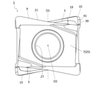
- FIG. 2 is a top view of the cutting insert shown in FIG. 1 as seen from above
- FIG. 3 is the same top view as the cutting insert shown in FIG. 2
- FIG. 2 is a bottom view of the cutting insert shown in FIG. 1 as seen from below
- FIG. It is the side view which looked at the cutting insert shown in FIG. 2 from A1 direction.
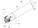
- 1 is a perspective view of a non-limiting one-sided cutting tool of the present disclosure
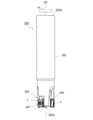
- FIG. FIG. 9 is a side view of the cutting tool shown in FIG.
- FIG. 1 is a schematic diagram illustrating a step in the non-limiting method of manufacturing a one-sided machined workpiece of the present disclosure
- FIG. 1 is a schematic diagram illustrating a step in the non-limiting method of manufacturing a one-sided machined workpiece of the present disclosure
- FIG. 1 is a schematic diagram illustrating a step in the non-limiting method of manufacturing a one-sided machined workpiece of the present disclosure
- FIG. 1 is a schematic diagram illustrating a step in the non-limiting method of manufacturing a one-sided machined workpiece of the present disclosure
- insert 1 a non-limiting one-sided cutting insert 1 (hereinafter sometimes referred to as "insert 1") of the present disclosure will be described in detail with reference to the drawings.
- insert 1 may comprise any components not shown in the referenced figures.
- the dimensions of the members in each drawing do not faithfully represent the actual dimensions of the constituent members, the dimensional ratios of the respective members, and the like.
- the insert 1 may have an upper surface 3, a lower surface 5, side surfaces 7 and an upper cutting edge 9, as in one non-limiting example shown in FIGS.
- the upper surface 3 and the lower surface 5 are expressions for convenience and do not indicate upward and downward directions.
- top surface 3 need not face upwards when insert 1 is used.
- the upper surface 3 may be polygonal.
- the lower surface 5 may also be located opposite the upper surface 3 .
- the lower surface 5, like the upper surface 3, may be polygonal.
- the insert 1 may have a polygonal plate shape.
- the top surface 3 may be rectangular.
- the polygonal shape does not have to be strictly a polygonal shape.
- the sides of the upper surface 3 may not be strictly straight lines, and may be curved when the upper surface 3 is viewed from the front (top view).
- the corners of the upper surface 3 located between the sides adjacent to each other may not be exact corners. In other words, the corners on the upper surface 3 may not be exact corners.
- the corner may have a convex curved shape when viewed from above, or may have a shape combining a straight line and a curved line. These points are the same for the lower surface 5 as well.
- An imaginary straight line passing through the center of the upper surface 3 and the center of the lower surface 5 may be the central axis O1 of the insert 1.
- the diagonal corners of the top surface 3 may be connected by straight lines, and the intersection of these straight lines may be the center of the top surface 3 .
- the starting point of the diagonal line may be the intersection of the extension lines of the sides forming the polygonal shape.
- the center of the upper surface 3 may be the position of the center of gravity of the upper surface 3 when viewed from above.
- the center of the bottom surface 5 may be defined similarly to the center of the top surface 3 .
- the upper surface 3 may be rotationally symmetrical at 180° around the central axis O1 when viewed from above. Further, the lower surface 5 may be rotationally symmetrical about the central axis O1 by 180° when the lower surface 5 is viewed from the front (bottom view).
- the lower surface 5 may have a planar area 11 centrally located on the lower surface 5, as in a non-limiting example shown in FIG.
- Planar area 11 can function as a seating surface. That is, when the upper cutting edge 9 is used to manufacture a machined workpiece, the planar region 11 can abut (contact) the holder when the insert 1 is attached to the holder.
- the planar area 11 may be a flat surface area. Flat does not have to be flat in the strictest sense.
- the planar region 11 may be substantially flat, or may be slightly curved or have slight irregularities that are not noticeable when the insert 1 is viewed as a whole. For example, the planar region 11 may have slight unevenness of about several tens of ⁇ m.
- the flat area 11 may be positioned so as to include the central axis O1. Moreover, the planar region 11 may be orthogonal to the central axis O1. Orthogonality is not limited to strict orthogonality, and may mean that a range of about 90° ⁇ 5° is allowed.
- the insert 1 is not limited to a specific size.
- the maximum width when the upper surface 3 is viewed from above may be set to approximately 4 to 25 mm.
- the height from the upper surface 3 to the lower surface 5 may be set to about 5 to 20 mm.
- the height from the upper surface 3 to the lower surface 5 may mean the maximum value of the distance between the upper surface 3 and the lower surface 5 in the direction parallel to the central axis O1.
- the height from the upper surface 3 to the lower surface 5 may be rephrased as the width of the side surface 7 in the direction along the central axis O1.
- the side surface 7 may be located between the upper surface 3 and the lower surface 5. Sides 7 may be connected to upper surface 3 and lower surface 5, as in one non-limiting example shown in FIGS.
- the upper cutting edge 9 may be located at the intersection of the upper surface 3 and the side surface 7.
- the upper cutting edge 9 can be used for cutting a work material when using the insert 1 to manufacture a machined product.
- the intersection of the upper surface 3 and the side surface 7 on which the upper cutting edge 9 is located is macroscopically linear, but microscopically may have a slight width.
- the intersection of the top surface 3 and the side surfaces 7 may be honed, and the top surface 3 and the side surfaces 7 may be connected by a convex curved surface.
- the upper cutting edge 9 is microscopically shown as a convex curve instead of a point in the cross section intersecting the upper surface 3 and the side surface 7 .
- the durability of the upper cutting edge 9 is high.
- the upper cutting edge 9 may be positioned over the entire intersection, or may be positioned only at a part of the intersection.
- the upper cutting edge 9 may have a linear shape or a curved shape when the side surface 7 is viewed from the front (side view). Further, the upper cutting edge 9 may have a shape that combines a straight line and a curved line when viewed from the side.
- one of the top surface 3 and the side surface 7 may have a rake area, and the other of the top surface 3 and the side surface 7 may have a flank area. good.
- the top surface 3 may have a rake area and the side surface 7 may have a flank area.
- the insert 1 may have a lower cutting edge 13.
- the bottom cutting edge 13 may be located at the intersection of the bottom surface 5 and the side surface 7 .
- the lower cutting edge 13 can be used to cut a workpiece when the insert 1 is used to manufacture a machined product.
- the lower cutting edge 13 may be positioned over the entire intersection, or may be positioned only at a portion of the intersection.
- the lower cutting edge 13 may have a linear shape or a curved shape when viewed from the side. Further, the lower cutting edge 13 may have a shape that combines a straight line and a curved line when viewed from the side.
- the insert 1 when the insert 1 has the upper cutting edge 9 and the lower cutting edge 13, the insert 1 can be double-sided.
- the plurality of corners on the upper surface 3 may include a first corner 15 and a second corner 17.
- the plurality of sides on the upper surface 3 may include the first side 19 and the second side 21 . That is, the top surface 3 may have a first corner 15 , a second corner 17 , a first side 19 and a second side 21 .
- the first side 19 is connected to the first corner 15 and the second corner 17, and from the end 19a connected to the first corner 15 to the second corner 17, as a non-limiting example shown in FIG. You may incline so that the lower surface 5 may be approached as it goes to the edge part 19b which was cut. Also, the second side 21 may be located on the opposite side of the first side 19 . The second side 21 may be located on the opposite side of the first side 19 with respect to the central axis O1.
- the first side 19 and the second side 21 may have the same length or may have different lengths. As a non-limiting example shown in FIG. 1, the first side 19 and the second side 21 may be the same length as each other. The first side 19 and the second side 21 may each be one of the longer sides of the rectangular upper surface 3 .
- the side surface 7 may have the first side surface 23 .
- the first side 23 may be connected to the first side 19 .
- the side surface 7 may further have a second side surface 25 in addition to the first side surface 23 .
- the second side 25 may be connected to the second side 21 .
- the insert 1 may have through-holes 27 that open at the first side surface 23 and the second side surface 25 .
- the through-holes 27 can be used, for example, to insert screws when fixing the insert 1 to the holder.
- a clamp member may be used instead of the screw.
- the first side 23 and the second side 25 may have flattened areas in their respective central portions. Through holes 27 may be located in these flat areas.
- the through hole 27 may be opened at the center of the first side surface 23 and the center of the second side surface 25 .
- the center of the first side 23 and the center of the second side 25 may be defined similarly to the center of the top surface 3 .
- An imaginary straight line passing through the center of the first side surface 23 and the center of the second side surface 25 may be the central axis O2 of the through hole 27 .
- the central axis O2 of the through hole 27 may be orthogonal to the central axis O1 of the insert 1.
- the through-hole 27 is not limited to the configuration in which it opens at the first side surface 23 and the second side surface 25 .
- the through-holes 27 may open, for example, at the upper surface 3 and the lower surface 5 .
- the upper surface 3 may have a land surface.
- a land surface may refer to a narrow band-like surface area located along a side of the top surface 3 .
- a land surface may be used to increase the durability of the upper cutting edge 9 .
- the land surface In the cross-section of the top surface 3 orthogonal to the sides, the land surface is the area represented by the straight line adjacent to the sides. If the upper cutting edge 9 is indicated by a dot in the cross section intersecting the upper surface 3 and the side surface 7 , the land surface is a straight area extending from the upper cutting edge 9 indicated by the dot toward the center of the upper surface 3 .
- the land surface is a linear area extending from the upper cutting edge 9 shown by this convex curve toward the center of the upper surface 3. be.
- the boundary between the land face and the rake face region is macroscopically shown as a bent portion. That is, in the cross section that intersects the upper surface 3 and the side surface 7, the inner end of the linear region corresponding to the land surface is the inner end of the land surface.
- the upper surface 3 may have a first land surface 29 as in a non-limiting example shown in FIG.
- the first land surface 29 may be positioned along the first side 19 . 2 and 3, the first side 19 has a convex shape protruding outward when viewed from the top, and has a vertex farthest from the second side 21. 31.
- the width W1 of the first land surface 29 positioned along the first side 19 may not be constant.
- the first land surface 29 may have a first region 33 and a second region 35 .
- the width W11 of the first land surface 29 in the first region 33 may become narrower as the distance from the first corner 15 increases.
- the second region 35 may be located closer to the second corner 17 than the first region 33, and the width W12 of the first land surface 29 in the second region 35 increases as the distance from the first corner 15 increases. You can become
- the width of the first land surface 29 is narrow. Therefore, the portion of the upper cutting edge 9 along the boundary 37 is relatively sharp and can function as a so-called wiper edge.
- a boundary 37 between the first region 33 and the second region 35 may be located closer to the second corner 17 than the apex 31 . In other words, the interval L11 between the second corner 17 and the boundary 37 may be smaller than the interval L12 between the second corner 17 and the top portion 31 .
- the cutting load tends to concentrate on the apex 31 of the first side 19 .
- the width W1 of the first land surface 29 is the smallest, so the durability tends to be the lowest.
- the boundary 37 is located closer to the second corner 17 than the top 31, the position of the top 31 where the cutting load tends to concentrate and the position of the boundary 37 where the durability tends to be the lowest can be shifted. It is easy to avoid an excessive decrease in sexuality.
- the boundary 37 is located closer to the second corner 17 than the top portion 31, even in high-cutting machining in which the first side 19 is used as a cutting edge to near the second corner 17 rather than the top portion 31, the machined surface is improved. Easy to improve surface accuracy. Therefore, according to the insert 1, it has durability and the surface accuracy of the machined surface is high.
- first side 19 may have a convex curved shape when viewed from above.
- second side 21 may have a convex curved shape when viewed from above.
- the top portion 31 may be a portion located on the outermost side of the first side 19 when viewed from above.
- the top portion 31 may be located in the center of the first side 19 .
- the second side 21 is located on the opposite side of the first side 19 with respect to the central axis O1, and when viewed from the top, the upper surface 3 is located on the central axis O1. is 180° rotationally symmetrical about .
- the top portion 31 can be positioned on an imaginary straight line passing through the center of the first side surface 23 and the center of the second side surface 25 . That is, the top portion 31 can be positioned on the central axis O2 of the through hole 27 when viewed from above.
- the first side 19 has a convex curved shape in a top view means that the first side 19 is not strictly linear.
- the fact that the plurality of corners on the upper surface 3 has a convex curved shape means that the plurality of corners including the first corner 15 and the second corner 17 are not corners in the strict sense. . Therefore, when the first side 19 and the plurality of corners have a convex curved shape, the radius of curvature of the first side 19 is several tens of times or more the radius of curvature of the plurality of corners. is required that the upper surface 3 is generally polygonal. This is the same for the second side 21 as well.
- the width W11 of the first land surface 29 in the first region 33 and the width W12 of the first land surface 29 in the second region 35 are the dimensions in the direction orthogonal to the first side 19.
- the configuration in which the width W11 becomes narrower as it moves away from the first corner 15 may mean that the width W11 does not become wider as it moves away from the first corner 15 . Therefore, the width W11 may be partially constant.
- the first region 33 may include a region with a constant width W11. These points may be similarly defined for the width W12.
- the configuration in which the width W12 widens with distance from the first corner 15 may mean that the width W12 does not narrow with distance from the first corner 15 .
- the second region 35 may include a region with a constant width W12.
- the second region 35 may be connected to the first region 33 at the end 35a on the side of the first corner 15, as in a non-limiting example shown in FIG.
- the first land surface 29 continues from the first area 33 to the second area 35 . That is, the first land surface 29 also exists at the boundary 37 between the first area 33 and the second area 35 . Therefore, the boundary 37 is less likely to become a sharp edge and less likely to be lost.
- the second region 35 may have an end portion 35 b on the second corner 17 side away from the second corner 17 .
- the upper cutting edge 9 does not have to be positioned between the end portion 35b and the second corner 17 .
- the first region 33 may be connected to the first corner 15 at the end 33 a on the first corner 15 side.
- the second corner 17 may be located closer to the boundary 37 than the first corner 15.
- the spacing L11 between the second corner 17 and the boundary 37 may be less than the spacing L2 between the first corner 15 and the boundary 37, as in one non-limiting example shown in FIG.
- the apex 31 may be located closer to the boundary 37 than the second corner 17.
- the distance L3 between the top portion 31 and the boundary 37 may be smaller than the distance L11 between the second corner 17 and the boundary 37 .
- the interval L3 is larger than the interval L11, the range of cutting heights in which the top portion 31 contacts the work material but the boundary 37 does not contact the work material is widened.
- the interval L3 is smaller than the interval L11, the range of cutting heights in which the top portion 31 contacts the work material and the boundary 37 contacts the work material widens. In other words, the range of cutting depths in which the portion of the upper cutting edge 9 along the boundary 37 can function as a wiper edge is widened.
- the maximum value of the width W11 of the first land surface 29 in the first region 33 may be the same as or different from the maximum value of the width W12 of the first land surface 29 in the second region 35 .
- the maximum value of the width W11 is the same as the maximum value of the width W12, variations in wear of the rake face are easily suppressed. Therefore, it is easy to suppress variations in chip disposal performance and reduction in the strength of the upper cutting edge 9 .
- the fact that the maximum value of the width W11 is the same as the maximum value of the width W12 does not mean that the two values are strictly the same. For example, there may be a difference of about 10% between the two values.
- the first region 33 may have the maximum value of the width W11 of the first land surface 29 in the first region 33 at the end 33a on the side of the first corner 15 .
- the second region 35 may have the maximum value of the width W12 of the first land surface 29 in the second region 35 at the end 35b on the side of the second corner 17 .
- the top surface 3 may further have a third side 39 and a second land surface 41, as in a non-limiting example shown in FIG.
- the third side 39 may be connected to the first corner 15 on the side opposite the first side 19 .
- the second land surface 41 may be positioned along the third side 39 .
- the maximum value of the width W2 of the second land surface 41 may be the same as or different from the maximum value of the width W1 of the first land surface 29.
- the maximum width W2 may be greater than the maximum width W1, as in one non-limiting example shown in FIG.
- the durability of the third side 39 can be easily increased in, for example, plunge machining in which the third side 39 is used as a cutting edge.
- the width W2 of the second land surface 41 may be constant or may vary.
- the degree of freedom in cutting is likely to be increased.
- stable chipping resistance can be ensured even in machining such as thrust machining in which cross-cutting changes.
- the width W1 of the first land surface 29 and the width W2 of the second land surface 41 are not limited to specific sizes.
- the maximum value of the width W1 of the first land surface 29 may be set to approximately 0.05 to 0.35 mm.
- the maximum value of the width W2 of the second land surface 41 may be set to approximately 0.1 to 0.4 mm.
- the second land surface 41 may have the maximum value of the width W2 of the second land surface 41 at the end far from the first corner 15. good.
- the third side 39 may be shorter than the first side 19 and the second side 21 as in the non-limiting example shown in FIG.
- the third side 39 may be one of the short sides of the rectangular top surface 3 .
- Examples of materials for the insert 1 include cemented carbide and cermet.
- Cemented carbide compositions may include, for example, WC-Co, WC-TiC-Co and WC-TiC-TaC-Co.
- WC, TiC and TaC may be hard particles and Co may be the binder phase.
- the cermet may be a sintered composite material in which a metal is combined with a ceramic component.
- An example of a cermet may be a titanium compound based on titanium carbide (TiC) or titanium nitride (TiN).
- TiC titanium carbide
- TiN titanium nitride
- the material of the insert 1 is not limited to the above composition.
- the surface of the insert 1 may be coated with a coating using chemical vapor deposition (CVD) or physical vapor deposition (PVD) methods.
- the composition of the coating may include, for example, titanium carbide (TiC), titanium nitride (TiN), titanium carbonitride ( TiCN ), and alumina ( Al2O3 ).
- FIG. 8 a non-limiting cutting tool 101 of the present disclosure will be described with reference to FIGS. 8 to 10.
- FIG. Note that, as in a non-limiting example shown in FIG. 8 and the like, the rotation axis O3 of the cutting tool 101 may be indicated by a two-dot chain line, and the rotation direction of the rotation axis O3 may be indicated by an arrow Y1.
- the cutting tool 101 may have a holder 103 and an insert 1, as a non-limiting example shown in FIGS. 8-10.
- the insert 1 has durability and the surface accuracy of the machined surface is high, so excellent cutting performance can be exhibited.
- the cutting tool 101 is rotatable around the rotation axis O3. Moreover, the cutting tool 101 may be used for milling.
- the holder 103 may have a cylindrical shape extending from the first end 103a to the second end 103b along the rotation axis O3.
- the cylindrical shape may be a substantially cylindrical shape, and does not have to be a cylindrical shape in a strict sense.
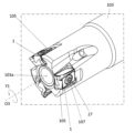
- the holder 103 may have a pocket 105 located on the side of the first end 103a.
- An insert 1 can be attached to the pocket 105 .
- the pocket 105 may be open on the outer peripheral surface of the holder 103 and the end surface on the side of the first end 103a.
- the insert 1 may be positioned within the pocket 105.
- the number of pockets 105 may be one or more. If the holder 103 has multiple pockets 105 , the cutting tool 101 may have multiple inserts 1 , and one insert 1 may be located in each pocket 105 .
- these pockets 105 may be positioned at equal intervals around the rotation axis O3, or may be positioned at unequal intervals.
- the insert 1 may be mounted in the pocket 105 so that at least part of the cutting edge protrudes from the holder 103.
- the insert 1 may be mounted in the holder 103 such that the upper cutting edge 9 protrudes from the holder 103 toward the workpiece.
- the lower surface 5 and side surfaces 7 may abut against the holder 103 .
- the insert 1 is attached to the holder 103 so that the first corner 15 is closer to the first end 103 a than the second corner 17 and the first side 19 is closer to the outer periphery than the second side 21 .
- the boundary 37 may be located closer to the second end 103b than the top portion 31 is.
- the insert 1 may be attached to the pocket 105 by a screw 107. That is, by inserting a screw 107 into the through-hole 27 of the insert 1, inserting the tip of the screw 107 into a screw hole formed in the pocket 105, and fixing the screw 107 to the screw hole, the insert 1 is attached to the holder 103. may be attached to the
- Examples of materials for the holder 103 include steel and cast iron. When the material of the holder 103 is steel, the toughness of the holder 103 is high.
- the cutting workpiece 201 may be produced by cutting a workpiece 203 .
- the method for manufacturing the cut workpiece 201 may include the following steps. i.e. (1) rotating the cutting tool 101 represented by the above non-limiting embodiment; (2) contacting the rotating cutting tool 101 with the work material 203; (3) separating the cutting tool 101 from the work material 203; may be provided.
- the cutting tool 101 may be relatively brought closer to the work material 203 while rotating in the Y1 direction around the rotation axis O3.
- the upper cutting edge 9 of the cutting tool 101 may be brought into contact with the work material 203 to cut the work material 203 .
- the cutting tool 101 may be kept relatively away from the work material 203 .
- the work material 203 is fixed and the cutting tool 101 is moved in each process, but it is of course not limited to such a form.
- step (1) the work material 203 may be brought closer to the cutting tool 101 .
- step (3) the work material 203 may be kept away from the cutting tool 101 .
- the process of keeping the cutting tool 101 rotated and bringing the upper cutting edge 9 of the insert 1 into contact with different portions of the work piece 203 may be repeated.
- Examples of materials for the work material 203 include carbon steel, alloy steel, stainless steel, cast iron, and non-ferrous metals.
Landscapes
- Engineering & Computer Science (AREA)
- Mechanical Engineering (AREA)
- Milling Processes (AREA)
- Cutting Tools, Boring Holders, And Turrets (AREA)
Priority Applications (1)
| Application Number | Priority Date | Filing Date | Title |
|---|---|---|---|
| JP2023554437A JP7763261B2 (ja) | 2021-10-11 | 2022-10-05 | 切削インサート、切削工具及び切削加工物の製造方法 |
Applications Claiming Priority (2)
| Application Number | Priority Date | Filing Date | Title |
|---|---|---|---|
| JP2021-166569 | 2021-10-11 | ||
| JP2021166569 | 2021-10-11 |
Publications (1)
| Publication Number | Publication Date |
|---|---|
| WO2023063183A1 true WO2023063183A1 (ja) | 2023-04-20 |
Family
ID=85988615
Family Applications (1)
| Application Number | Title | Priority Date | Filing Date |
|---|---|---|---|
| PCT/JP2022/037249 Ceased WO2023063183A1 (ja) | 2021-10-11 | 2022-10-05 | 切削インサート、切削工具及び切削加工物の製造方法 |
Country Status (2)
| Country | Link |
|---|---|
| JP (1) | JP7763261B2 (https=) |
| WO (1) | WO2023063183A1 (https=) |
Cited By (1)
| Publication number | Priority date | Publication date | Assignee | Title |
|---|---|---|---|---|
| WO2025216120A1 (ja) * | 2024-04-08 | 2025-10-16 | 京セラ株式会社 | 切削インサート、切削工具及び切削加工物の製造方法 |
Citations (6)
| Publication number | Priority date | Publication date | Assignee | Title |
|---|---|---|---|---|
| JP2007144625A (ja) * | 2004-04-06 | 2007-06-14 | Mitsubishi Materials Corp | 切削インサートおよびインサート着脱式転削工具 |
| JP2012161907A (ja) * | 2011-01-18 | 2012-08-30 | Mitsubishi Materials Corp | 切削インサートおよび刃先交換式切削工具 |
| JP2013535351A (ja) * | 2010-08-13 | 2013-09-12 | インガーソル カッティング ツール カンパニー | コーナ側面に凹状の逃げくぼみが形成された切削インサート |
| JP2014000666A (ja) * | 2012-06-14 | 2014-01-09 | Korloy Inc | 両面型切削インサート |
| JP2014111309A (ja) * | 2007-11-28 | 2014-06-19 | Iscar Ltd | 接線方向切削インサート |
| JP2015100901A (ja) * | 2013-11-27 | 2015-06-04 | 京セラ株式会社 | 切削インサート、切削工具および被削加工物の製造方法 |
Family Cites Families (2)
| Publication number | Priority date | Publication date | Assignee | Title |
|---|---|---|---|---|
| CN107297531B (zh) * | 2011-10-31 | 2019-11-22 | 京瓷株式会社 | 切削镶刀 |
| JP6701784B2 (ja) * | 2016-02-17 | 2020-05-27 | 株式会社リコー | 液体吐出ヘッド、液体吐出ユニット及び液体を吐出する装置 |
-
2022
- 2022-10-05 JP JP2023554437A patent/JP7763261B2/ja active Active
- 2022-10-05 WO PCT/JP2022/037249 patent/WO2023063183A1/ja not_active Ceased
Patent Citations (6)
| Publication number | Priority date | Publication date | Assignee | Title |
|---|---|---|---|---|
| JP2007144625A (ja) * | 2004-04-06 | 2007-06-14 | Mitsubishi Materials Corp | 切削インサートおよびインサート着脱式転削工具 |
| JP2014111309A (ja) * | 2007-11-28 | 2014-06-19 | Iscar Ltd | 接線方向切削インサート |
| JP2013535351A (ja) * | 2010-08-13 | 2013-09-12 | インガーソル カッティング ツール カンパニー | コーナ側面に凹状の逃げくぼみが形成された切削インサート |
| JP2012161907A (ja) * | 2011-01-18 | 2012-08-30 | Mitsubishi Materials Corp | 切削インサートおよび刃先交換式切削工具 |
| JP2014000666A (ja) * | 2012-06-14 | 2014-01-09 | Korloy Inc | 両面型切削インサート |
| JP2015100901A (ja) * | 2013-11-27 | 2015-06-04 | 京セラ株式会社 | 切削インサート、切削工具および被削加工物の製造方法 |
Cited By (1)
| Publication number | Priority date | Publication date | Assignee | Title |
|---|---|---|---|---|
| WO2025216120A1 (ja) * | 2024-04-08 | 2025-10-16 | 京セラ株式会社 | 切削インサート、切削工具及び切削加工物の製造方法 |
Also Published As
| Publication number | Publication date |
|---|---|
| JP7763261B2 (ja) | 2025-10-31 |
| JPWO2023063183A1 (https=) | 2023-04-20 |
Similar Documents
| Publication | Publication Date | Title |
|---|---|---|
| JP7480291B2 (ja) | 切削インサート、切削工具及び切削加工物の製造方法 | |
| JPWO2016017470A1 (ja) | 切削インサート、切削工具及び切削加工物の製造方法 | |
| WO2021193709A1 (ja) | 切削インサート、切削工具及び切削加工物の製造方法 | |
| WO2019065525A1 (ja) | 切削インサート、切削工具及び切削加工物の製造方法 | |
| WO2016190351A1 (ja) | 切削インサート、切削工具及びこれを用いた切削加工物の製造方法 | |
| WO2021193705A1 (ja) | 回転工具及び切削加工物の製造方法 | |
| JPWO2017090770A1 (ja) | 切削インサート、切削工具及び切削加工物の製造方法 | |
| CN109562460B (zh) | 切削刀片、切削工具以及切削加工物的制造方法 | |
| JP6542975B2 (ja) | インサート、切削工具及び切削加工物の製造方法 | |
| CN110944777B (zh) | 切削刀片、切削工具以及切削加工物的制造方法 | |
| WO2023063183A1 (ja) | 切削インサート、切削工具及び切削加工物の製造方法 | |
| JP7114733B2 (ja) | 切削インサート、切削工具及び切削加工物の製造方法 | |
| JP7573759B2 (ja) | 切削インサート、切削工具及び切削加工物の製造方法 | |
| JP7733214B2 (ja) | 切削インサート、切削工具、及び切削加工物の製造方法 | |
| WO2021005951A1 (ja) | 切削インサート、切削工具及び切削加工物の製造方法 | |
| JP2020069598A (ja) | 切削インサート、切削工具、及び切削加工物の製造方法 | |
| KR102540681B1 (ko) | 절삭 인서트, 절삭 공구 및 절삭 가공물의 제조 방법 | |
| CN110997204A (zh) | 切削刀片、切削工具以及切削加工物的制造方法 | |
| JP7257230B2 (ja) | 切削インサート、切削工具、及び切削加工物の製造方法 | |
| JP7344385B2 (ja) | 切削インサート、切削工具及び切削加工物の製造方法 | |
| JP7445758B2 (ja) | 切削インサート、切削工具及び切削加工物の製造方法 | |
| JP7706641B2 (ja) | 切削インサート、切削工具、及び切削加工物の製造方法 | |
| JP7117389B2 (ja) | 切削インサート、切削工具及び切削加工物の製造方法 | |
| JP7344168B2 (ja) | 切削インサート、切削工具及び切削加工物の製造方法 |
Legal Events
| Date | Code | Title | Description |
|---|---|---|---|
| 121 | Ep: the epo has been informed by wipo that ep was designated in this application |
Ref document number: 22880879 Country of ref document: EP Kind code of ref document: A1 |
|
| WWE | Wipo information: entry into national phase |
Ref document number: 2023554437 Country of ref document: JP |
|
| NENP | Non-entry into the national phase |
Ref country code: DE |
|
| 122 | Ep: pct application non-entry in european phase |
Ref document number: 22880879 Country of ref document: EP Kind code of ref document: A1 |