WO2023063153A1 - クラッチ装置および自動二輪車 - Google Patents
クラッチ装置および自動二輪車 Download PDFInfo
- Publication number
- WO2023063153A1 WO2023063153A1 PCT/JP2022/037003 JP2022037003W WO2023063153A1 WO 2023063153 A1 WO2023063153 A1 WO 2023063153A1 JP 2022037003 W JP2022037003 W JP 2022037003W WO 2023063153 A1 WO2023063153 A1 WO 2023063153A1
- Authority
- WO
- WIPO (PCT)
- Prior art keywords
- pressure
- center
- clutch
- plate
- rotating plate
- Prior art date
- Legal status (The legal status is an assumption and is not a legal conclusion. Google has not performed a legal analysis and makes no representation as to the accuracy of the status listed.)
- Ceased
Links
Images




Classifications
-
- F—MECHANICAL ENGINEERING; LIGHTING; HEATING; WEAPONS; BLASTING
- F16—ENGINEERING ELEMENTS AND UNITS; GENERAL MEASURES FOR PRODUCING AND MAINTAINING EFFECTIVE FUNCTIONING OF MACHINES OR INSTALLATIONS; THERMAL INSULATION IN GENERAL
- F16D—COUPLINGS FOR TRANSMITTING ROTATION; CLUTCHES; BRAKES
- F16D13/00—Friction clutches
- F16D13/58—Details
- F16D13/74—Features relating to lubrication
-
- F—MECHANICAL ENGINEERING; LIGHTING; HEATING; WEAPONS; BLASTING
- F16—ENGINEERING ELEMENTS AND UNITS; GENERAL MEASURES FOR PRODUCING AND MAINTAINING EFFECTIVE FUNCTIONING OF MACHINES OR INSTALLATIONS; THERMAL INSULATION IN GENERAL
- F16D—COUPLINGS FOR TRANSMITTING ROTATION; CLUTCHES; BRAKES
- F16D13/00—Friction clutches
- F16D13/22—Friction clutches with axially-movable clutching members
- F16D13/38—Friction clutches with axially-movable clutching members with flat clutching surfaces, e.g. discs
- F16D13/52—Clutches with multiple lamellae ; Clutches in which three or more axially moveable members are fixed alternately to the shafts to be coupled and are pressed from one side towards an axially-located member
-
- F—MECHANICAL ENGINEERING; LIGHTING; HEATING; WEAPONS; BLASTING
- F16—ENGINEERING ELEMENTS AND UNITS; GENERAL MEASURES FOR PRODUCING AND MAINTAINING EFFECTIVE FUNCTIONING OF MACHINES OR INSTALLATIONS; THERMAL INSULATION IN GENERAL
- F16D—COUPLINGS FOR TRANSMITTING ROTATION; CLUTCHES; BRAKES
- F16D23/00—Details of mechanically-actuated clutches not specific for one distinct type
- F16D23/12—Mechanical clutch-actuating mechanisms arranged outside the clutch as such
-
- F—MECHANICAL ENGINEERING; LIGHTING; HEATING; WEAPONS; BLASTING
- F16—ENGINEERING ELEMENTS AND UNITS; GENERAL MEASURES FOR PRODUCING AND MAINTAINING EFFECTIVE FUNCTIONING OF MACHINES OR INSTALLATIONS; THERMAL INSULATION IN GENERAL
- F16D—COUPLINGS FOR TRANSMITTING ROTATION; CLUTCHES; BRAKES
- F16D23/00—Details of mechanically-actuated clutches not specific for one distinct type
- F16D23/12—Mechanical clutch-actuating mechanisms arranged outside the clutch as such
- F16D2023/123—Clutch actuation by cams, ramps or ball-screw mechanisms
Definitions
- the present invention relates to a clutch device that transmits and interrupts the rotational driving force of a drive shaft that is rotationally driven by a prime mover to a driven shaft that drives a driven body, and a motorcycle equipped with the same.
- a motor is placed between a prime mover such as an engine and a driven body such as a wheel to transmit or block the rotational driving force of the prime mover to the driven body.
- a clutch device is used in In general, a clutch device has a plurality of input-side rotating plates that are rotated by the rotational driving force of a prime mover and a plurality of output-side rotating plates that are connected to a driven body. It is possible to arbitrarily transmit or block the rotational driving force by bringing the rotary plate into close contact with or away from it.
- Patent Document 1 describes a center clutch that is connected to a driven body via a shaft and holds the output-side rotating plate, and a pressure clutch that presses the output-side rotating plate held by the center clutch.
- a clutch device is disclosed which is axially slidably fitted to the inner peripheral portion of the center side fitting portion of the.
- the center-side fitting portion is located between the output-side rotating plate and the input-side rotating plate, which are radially outer positions in the clutch device, in consideration of the diffusibility in the clutch device of the clutch oil flowing out from the tip of the shaft. It is formed near the inner periphery.
- the present invention has been made to address the above problem, and its object is to provide a clutch device that can be downsized in device configuration and a motorcycle equipped with the same.
- the present invention is characterized in that, in a clutch device for transmitting or interrupting the rotational driving force of a driving shaft to a driven shaft, an output is disposed facing an input-side rotating plate that is rotationally driven by the rotational driving of the driving shaft.
- a clutch center that has a plate holding portion that holds a side rotating plate and is rotationally driven together with a driven shaft, and an input side rotating plate or an output side that are disposed facing each other in a state that can be approached or separated from the clutch center and relatively rotatable.
- the driven shaft has an outflow portion at the tip for the clutch oil that has flowed in the shaft to flow out; and the clutch center is a driven shaft connection to which the tip of the driven shaft is connected.
- the plate pressure has a center fitting portion slidably fitted on the driven shaft connecting portion, and a cylindrical portion adjacent to the center fitting portion for receiving the clutch oil flowing out from the outflow portion of the driven shaft. It is to have a center tubular portion in which the oil receiving portion is formed respectively.
- the center fitting portion of the center tubular portion of the plate pressure is slidably externally fitted to the driven shaft connecting portion of the clutch center, and the center tubular portion receives the clutch oil flowing out from the outflow part of the driven shaft.
- the clutch oil flowing out from the driven shaft is effectively guided to the sliding portion between the clutch center and the plate pressure, and flowed outside the sliding portion (outside the center tubular portion) to lubricate the inside of the clutch device. can do. That is, the clutch device according to the present invention can be made small by providing the sliding portion between the clutch center and the plate pressure at the driven shaft connecting portion near the center of the clutch center, and the device configuration can be made compact. .
- the oil receiving portion has an inclined portion extending radially outward toward the center fitting portion on at least a part of the inner peripheral surface.
- the sliding portion between the clutch center and the plate pressure can be more effectively operated. and flows out to the outside of the sliding portion (the outside of the center tubular portion) to lubricate the inside of the clutch device.
- the center cylindrical portion spreads radially outward in a part of the circumference where the center fitting portion is formed so as to be in contact with the outer peripheral portion of the driven shaft connecting portion. It is to have an oil passage expansion part forming a gap therebetween.
- the clutch device spreads radially outward in a portion of the circumferential direction where the center fitting portion of the center cylindrical portion is formed, and is connected to the outer peripheral portion of the driven shaft connecting portion. Since there is an oil passage expansion portion forming a gap therebetween, the clutch oil in the center tubular portion can be effectively led out of the center tubular portion via the oil passage expansion portion. It is a matter of course that the gap formed between the oil passage expansion portion and the driven shaft connecting portion is larger than the gap formed between the driven shaft connecting portion and the center fitting portion.
- Another feature of the present invention is that, in the clutch device, the oil passage expansion portion is formed to extend from the center fitting portion to the oil receiving portion.
- the clutch device is formed such that the oil passage expansion portion extends from the center fitting portion to the extent that it reaches the oil receiving portion or enters the oil receiving portion. Therefore, the clutch oil in the center tubular portion can be effectively led out of the center tubular portion through the oil passage expansion portion.
- the center cylindrical portion has an opening partly cut away in a part of the circumferential direction where the center fitting portion is formed.
- the clutch device has an opening formed by notching a portion of the center cylindrical portion in the circumferential direction where the center fitting portion is formed. Therefore, the clutch oil in the center tubular portion can be effectively led out of the center tubular portion through the opening.
- Another feature of the present invention is that, in the clutch device, the opening is formed at a position facing the central portion of the plate holding portion in the axial direction.
- the opening of the clutch device is formed at a position facing the central portion of the plate holding portion in the axial direction. Through the opening, it can be effectively guided to the axially central portion of the plate holding portion outside the center cylindrical portion. That is, the clutch device supplies the clutch oil in the center tubular portion to the central portion where the input side rotating plate and the output side rotating plate are arranged side by side, and the entirety of these input side rotating plate and the output side rotating plate is efficiently supplied. clutch oil can be supplied.
- the central portion in the axial direction of the plate holding portion where the opening is formed includes not the central portion in the strict sense but the vicinity of the central portion in the strict sense.
- Another feature of the present invention is that, in the clutch device, the opening is formed extending from the center fitting portion to the oil receiving portion.
- the clutch device is formed so that the opening extends from the center fitting portion to the extent that it reaches the oil receiving portion or enters the oil receiving portion. , the clutch oil in the center tubular portion can be effectively led out of the center tubular portion through the opening.
- the present invention has been made to address the above problem, and its object is to provide a clutch device capable of supplying more clutch oil to the input-side rotating plate and the output-side rotating plate.
- the present invention is characterized in that, in a clutch device for transmitting or interrupting the rotational driving force of a driving shaft to a driven shaft, an output side rotating plate arranged opposite to an input side rotating plate rotationally driven by the rotational driving of the driving shaft is provided.
- a clutch center having a plate holding portion for holding and rotationally driven together with the driven shaft; a plate pressure for pressing the rotating plate; the driven shaft has an outflow portion at a tip portion through which clutch oil that has flowed in the shaft flows out; and the clutch center is connected to the tip portion of the driven shaft.
- the plate pressure has a center fitting portion that is slidably fitted onto the driven shaft coupling portion, and a part of the circumference in which the center fitting portion is formed.
- the clutch oil flowing out from the outflow portion of the driven shaft flows through the recess.
- the recess forms a gap with the outer peripheral portion of the driven shaft connecting portion, the clutch oil flowing through the recess more effectively flows out of the center cylindrical portion, More clutch oil can be supplied to the rotating plate.
- the clutch center is located radially outside of the driven shaft connecting portion, and when the clutch center rotates relative to the plate pressure, the input-side rotating plate and the output-side rotating plate rotate.
- a center-side assist cam surface that generates a force in a direction to bring the plate pressure closer to the clutch center in order to increase the pressing force with the side rotating plate;
- a plurality of center-side cam portions having center-side slipper cam surfaces that separate the plate pressure from the clutch center to reduce pressure, the plate pressure being positioned radially outward of the center tubular portion;
- the plate pressure is configured to be capable of coming into contact with the center-side assist cam surface when rotated relative to the clutch center, and increases the pressing force between the input-side rotating plate and the output-side rotating plate.
- a plurality of pressure-side cam portions having pressure-side slipper cam surfaces for separating the plate pressure from the clutch center, and the recesses are positioned between the pressure-side cam portions adjacent in the circumferential direction.
- the recess is positioned between the pressure-side cam portions that are adjacent in the circumferential direction.
- the clutch oil that has flowed through the concave portion and flowed out of the center tubular portion is made easier to flow through the input-side rotating plate and the output-side rotating plate.
- Another feature of the present invention is that, in the pressure-side cam portions that are adjacent in the circumferential direction, the pressure-side assist cam surface of one of the pressure-side cam portions and the pressure-side slipper cam surface of the other pressure-side cam portion are provided. are arranged facing each other in the circumferential direction, the recess is located on the pressure-side assist cam surface side.
- the recess is positioned on the pressure-side assist cam surface side.
- the clutch oil that has flowed out of the center cylindrical portion is effectively supplied to the pressure-side assist cam surface as well, so that wear on the pressure-side assist cam surface and the center-side assist cam surface can be reduced.
- Another feature of the present invention is that, in the pressure-side cam portions that are adjacent in the circumferential direction, the pressure-side assist cam surface of one of the pressure-side cam portions and the pressure-side slipper cam surface of the other pressure-side cam portion are provided. are arranged facing each other in the circumferential direction, the recess is located on the side of the pressure-side slipper cam surface.
- the recess is located on the pressure side slipper cam surface side. Since the stress applied to the pressure-side slipper cam surface is smaller than the stress applied to the pressure-assist cam surface, by providing a concave portion on the pressure-side slipper cam surface side, the strength of the center tubular portion can be maintained while maintaining the strength of the center tubular portion. Clutch oil can flow outside.
- the recess is formed from at least the central portion in the axial direction of the center tubular portion to the entire end portion on the clutch center side.
- the clutch oil that has flowed out of the outflow portion of the driven shaft can be more reliably flowed out of the center cylindrical portion, and more clutches can be produced by the input-side rotating plate and the output-side rotating plate.
- Can supply oil
- Another feature of the present invention is a clutch device for transmitting or interrupting the rotational driving force of a driving shaft to a driven shaft, in which an output-side rotating plate is arranged opposite to an input-side rotating plate that is rotationally driven by the rotational driving of the driving shaft.
- a clutch center having a plate holding portion for holding a plate and rotationally driven together with the driven shaft; a plate pressure that presses the output-side rotating plate; the driven shaft has an outflow portion at a tip portion through which clutch oil that has flowed in the shaft flows out; and the clutch center has the tip portion of the driven shaft a driven shaft connecting portion to be connected;
- the center-side assist cam surface In order to increase the pressure, the center-side assist cam surface generates a force in the direction to bring the plate pressure closer to the clutch center, and to reduce the pressing force between the input-side rotating plate and the output-side rotating plate.
- the plate pressure includes a center cylindrical portion that accommodates the tip portion of the driven shaft;
- the input-side rotating plate and the output-side rotating plate are positioned radially outwardly of the center tubular portion, and are configured to be able to contact with the center-side assist cam surface when rotated relative to the clutch center.
- a pressure-side assist cam surface that generates a force in a direction to bring the plate pressure closer to the clutch center in order to increase the pressing force of the input-side rotating plate, and the input-side rotating plate configured to be in contact with the center-side slipper cam surface.
- a plurality of pressure-side cam portions having pressure-side slipper cam surfaces separating the plate pressure from the clutch center in order to reduce the pressing force between the plate pressure and the output-side rotating plate; and the pressure-side cam portions adjacent in the circumferential direction. and a concave portion provided in the center tubular portion so as to spread between and radially outward, and through which the clutch oil flowing out from the outflow portion flows.
- the concave portion of the plate pressure is provided in the center cylindrical portion so as to be positioned between the pressure-side cam portions adjacent in the circumferential direction and at a position facing the driven shaft.
- Another feature of the present invention is that, in the pressure-side cam portions that are adjacent in the circumferential direction, the pressure-side assist cam surface of one of the pressure-side cam portions and the pressure-side slipper cam surface of the other pressure-side cam portion are provided. are arranged facing each other in the circumferential direction, the recess is located on the pressure-side assist cam surface side.
- the recess is positioned on the pressure-side assist cam surface side.
- the clutch oil that has flowed out of the center cylindrical portion is effectively supplied to the pressure-side assist cam surface as well, so that wear on the pressure-side assist cam surface and the center-side assist cam surface can be reduced.
- Another feature of the present invention is that, in the pressure-side cam portions that are adjacent in the circumferential direction, the pressure-side assist cam surface of one of the pressure-side cam portions and the pressure-side slipper cam surface of the other pressure-side cam portion are provided. are arranged facing each other in the circumferential direction, the recess is located on the side of the pressure-side slipper cam surface.
- the recess is located on the pressure side slipper cam surface side. Since the stress applied to the pressure-side slipper cam surface is smaller than the stress applied to the pressure-assist cam surface, by providing a concave portion on the pressure-side slipper cam surface side, the strength of the center tubular portion can be maintained while maintaining the strength of the center tubular portion. Clutch oil can flow outside.
- the recess is formed from at least the central portion in the axial direction of the center tubular portion to the entire end portion on the clutch center side.
- the clutch oil that has flowed out of the outflow portion of the driven shaft can be more reliably flowed out of the center cylindrical portion, and more clutches can be produced by the input-side rotating plate and the output-side rotating plate.
- Can supply oil
- Another feature of the present invention is a clutch device for transmitting or interrupting the rotational driving force of a driving shaft to a driven shaft, in which an output-side rotating plate is arranged opposite to an input-side rotating plate that is rotationally driven by the rotational driving of the driving shaft.
- a clutch center having a plate holding portion for holding a plate and rotationally driven together with the driven shaft; a plate pressure that presses the output-side rotating plate; the driven shaft has an outflow portion at a tip portion through which clutch oil that has flowed in the shaft flows out; and the clutch center has the tip portion of the driven shaft
- the plate pressure has a driven shaft connecting portion to be connected, and the plate pressure has a center cylindrical portion that accommodates the tip end portion of the driven shaft and has an opening that is cut at least partially in the circumferential direction.
- the central cylindrical portion of the plate pressure accommodates the tip portion of the driven shaft and has an opening partially notched in the circumferential direction.
- the oil flowing out of the outflow portion of the driven shaft flows out of the center cylindrical portion through the opening, so that more clutch oil can be supplied to the input-side rotating plate and the output-side rotating plate.
- the clutch center is located radially outside of the driven shaft connecting portion, and when the clutch center rotates relative to the plate pressure, the input-side rotating plate and the output-side rotating plate rotate.
- a center-side assist cam surface that generates a force in a direction to bring the plate pressure closer to the clutch center in order to increase the pressing force with the side rotating plate;
- a plurality of center-side cam portions having center-side slipper cam surfaces that separate the plate pressure from the clutch center to reduce pressure, the plate pressure being positioned radially outward of the center tubular portion;
- the plate pressure is configured to be capable of coming into contact with the center-side assist cam surface when rotated relative to the clutch center, and increases the pressing force between the input-side rotating plate and the output-side rotating plate.
- a plurality of pressure-side cam portions having a pressure-side slipper cam surface that separates the plate pressure from the clutch center, and the opening is located between the pressure-side cam portions that are adjacent in the circumferential direction. It is in.
- the opening is positioned between the pressure-side cam portions adjacent in the circumferential direction.
- the clutch oil that has flowed out of the center cylindrical portion through the opening can flow more easily through the input-side rotating plate and the output-side rotating plate.
- Another feature of the present invention is that, in the pressure-side cam portions that are adjacent in the circumferential direction, the pressure-side assist cam surface of one of the pressure-side cam portions and the pressure-side slipper cam surface of the other pressure-side cam portion are provided. are arranged facing each other in the circumferential direction, the opening is located on the side of the pressure-side assist cam surface.
- the opening is positioned on the pressure-side assist cam surface side.
- the clutch oil that has flowed out of the center cylindrical portion is effectively supplied to the pressure-side assist cam surface as well, so that wear on the pressure-side assist cam surface and the center-side assist cam surface can be reduced.
- Another feature of the present invention is that, in the pressure-side cam portions that are adjacent in the circumferential direction, the pressure-side assist cam surface of one of the pressure-side cam portions and the pressure-side slipper cam surface of the other pressure-side cam portion are provided. are arranged facing each other in the circumferential direction, the opening is located on the side of the pressure-side slipper cam surface.
- the opening is positioned on the pressure side slipper cam surface side. Since the stress applied to the pressure-side slipper cam surface is smaller than the stress applied to the pressure-assist cam surface, by providing a concave portion on the pressure-side slipper cam surface side, the strength of the center tubular portion can be maintained while maintaining the strength of the center tubular portion. Clutch oil can flow outside.
- Another feature of the present invention is that, in the pressure-side cam portions that are adjacent in the circumferential direction, the pressure-side assist cam surface of one of the pressure-side cam portions and the pressure-side slipper cam surface of the other pressure-side cam portion are provided. are arranged facing each other in the circumferential direction, the direction from one of the pressure-side cam portions to the other pressure-side cam portion in the circumferential direction is the first circumferential direction, and the direction from the other pressure-side cam portion is the first circumferential direction.
- the opening extends from the end of the pressure-side assist cam surface on the first circumferential direction side to the pressure-side slipper cam surface. It is formed up to the end on the second circumferential direction side.
- Another feature of the present invention is that when the direction in which the plate pressure approaches the clutch center is defined as a first direction and the direction in which the plate pressure moves away from the clutch center is defined as a second direction, the opening is is located on the first direction side relative to the second direction end of the pressure-side slipper cam surface.
- the end of the opening in the second direction is located on the first direction side relative to the end of the pressure-side slipper cam surface on the second direction side. be.
- Another feature of the present invention is that when the direction in which the plate pressure approaches the clutch center is defined as a first direction and the direction in which the plate pressure moves away from the clutch center is defined as a second direction, the opening is is located on the second direction side relative to the second direction end of the pressure-side slipper cam surface.
- the second direction end of the opening is located on the second direction side relative to the second direction side end of the pressure-side slipper cam surface.
- more clutch oil can be led from the opening to the outside of the center tubular portion.
- a large amount of clutch oil can be supplied to the input-side rotating plate and the output-side rotating plate located on the plate pressure side.
- the opening is comprises a first portion having a first length in the circumferential direction, and a second portion located on the second direction side of the first portion and having a shorter length in the circumferential direction than the first length. a second portion that is two in length.
- the opening includes a first portion having a first length in the circumferential direction and a second portion having a second length. As a result, more clutch oil can be led from the opening to the outside of the center tubular portion.
- Another feature of the present invention is that when the direction in which the plate pressure approaches the clutch center is defined as a first direction and the direction in which the plate pressure moves away from the clutch center is defined as a second direction, the opening is is formed in a U shape.
- the end of the opening in the second direction is formed in a U shape.
- concentration of stress on the opening can be suppressed, and sufficient strength of the central cylindrical portion can be ensured.
- FIG. 1 is a cross-sectional view showing an outline of the overall configuration of a clutch device according to one embodiment of the present invention with the clutch ON.
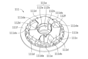
- 2 is a perspective view showing the configuration of the center fitting portion side of the plate pressure shown in FIG. 1.
- FIG. 3 is a perspective view showing the configuration of the center fitting portion side of the plate pressure according to the modification of the present invention.
- FIG. 4 is a perspective view showing the configuration of the center fitting portion side of a plate pressure according to another modification of the present invention.
- FIG. 5 is a perspective view showing the configuration of the center fitting portion side of a plate pressure according to another modification of the present invention.
- FIG. 6 is a perspective view showing the configuration of the center fitting portion side of a plate pressure according to another modification of the present invention.
- FIG. 7 is a perspective view showing the configuration of the clutch center shown in FIG. 1.
- FIG. 8 is a plan view showing the configuration of the center fitting portion side of the plate pressure shown in FIG. 1.
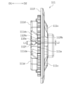
- FIG. 9 is a side view showing the configuration of the plate pressure shown in FIG. 1.
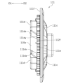
- FIG. 10 is a side view showing the configuration of a plate pressure according to another modification of the invention.
- FIG. 11 is a side view showing the configuration of a plate pressure according to another modification of the invention.
- FIG. 12 is a side view showing the configuration of a plate pressure according to another modification of the invention.
- FIG. 13 is a side view showing the configuration of a plate pressure according to another modification of the invention.
- FIG. 14 is a plan view showing the configuration of a plate pressure according to another modification of the invention.
- FIG. 1 is a cross-sectional view showing the outline of the overall configuration of a clutch device 100 according to the present invention.
- the clutch device 100 is a mechanical device for transmitting and interrupting the driving force of an engine (not shown), which is the prime mover of a two-wheeled vehicle (motorcycle), to wheels (not shown), which are driven bodies. It is arranged between a transmission (not shown).
- the clutch device 100 has a clutch outer 101 .
- the clutch outer 101 is a component for holding the input-side rotating plate 105 and for transmitting the driving force from the engine to the input-side rotating plate 105, and is formed by molding an aluminum alloy material into a bottomed cylindrical shape.
- a rotating plate holding portion 101a made of an internal gear-shaped spline is formed in the cylindrically formed portion of the clutch outer 101, and a plurality of (this In the embodiment, five input side rotating plates 105 are spline-fitted and held so as to be displaceable along the axial direction of the clutch outer 101 and integrally rotatable with the clutch outer 101 .
- a connecting hole 101b is formed in the central portion of the left side surface of the clutch outer 101, and a boss portion 103a of an input rotor 103, which will be described later, is slidably fitted into the connecting hole 101b. It is In this case, the input rotor 103 is attached to the clutch outer 101 via a rivet 102a, a side plate 102b, a torque damper 102c, and a separation spring 102d.
- the rivets 102a are a plurality of pin-like parts for regulating the displacement of the input rotor 103 in the axial direction and for arranging the side plate 102b on the plate surface of the input rotor 103.
- the side plate 102 b is a flat annular component for arranging the torque damper 102 c on the plate surface of the input rotor 103 .
- the torque damper 102c is a plurality of coil springs that elastically press the clutch outer 101 against the input rotor 103 in the circumferential direction.
- the separation spring 102d is a flat annular spring that presses the input rotor 103 axially away from the clutch outer 101 .
- the input rotor 103 is a metal gear part that rotates by meshing with a drive gear connected to a drive shaft (not shown) such as a crankshaft that is driven to rotate by a prime mover such as an engine.
- a boss portion 103a is rotatably supported by a shaft 120 via a needle bearing 104.
- the clutch outer 101 rotates integrally with the input rotor 103 independently of the shaft 120 at a position concentric with the shaft 120 .
- Shaft 120 is an example of a driven shaft.
- the input-side rotating plate 105 is a flat plate annular component that is pressed against the output-side rotating plate 106, and is formed by forming a thin plate material made of aluminum into an annular shape.
- the outer peripheral portion of each input-side rotary plate 105 is formed with external teeth that mesh with the internal-toothed splines of the clutch outer 101 .
- Friction materials composed of a plurality of pieces of paper are attached to both side surfaces (front and back surfaces) of the input side rotating plate 105, and oil grooves (not shown) are formed between the friction materials.
- the output-side rotating plate 106 is a flat annular component that is pressed against the input-side rotating plate 105, and is formed by punching a thin plate material made of SPCC (cold-rolled steel plate) into an annular shape.
- the output-side rotating plates 106 are alternately arranged with respect to the plurality of input-side rotating plates 105 inside the clutch outer 101 (five in this embodiment), and are applied to the clutch center 110 and the plate pressure 111 . retained respectively.
- Oil grooves (not shown) having a depth of several micrometers to several tens of micrometers for holding clutch oil are formed on both side surfaces (front and back surfaces) of each of these output-side rotating plates 106, and wear resistance is ensured. Surface hardening treatment is applied for the purpose of improvement.
- each output-side rotary plate 106 an internal gear-shaped plate is spline-fitted to a plate holding portion 110e formed on the clutch center 110 and a plate sub-holding portion 111e formed on the plate pressure 111, respectively.
- a spline is formed respectively.
- the friction material provided on each of the input side rotating plates 105 may of course be provided on each of the output side rotating plates 106 instead of the input side rotating plate 105 .
- Clutch center 110 is a part for accommodating output side rotating plate 106 together with input side rotating plate 105 and transmitting the driving force of the engine to the transmission side, and is formed by forming an aluminum alloy material into a substantially cylindrical shape. It is More specifically, clutch center 110 is mainly configured by integrally forming driven shaft connecting portion 110a, ring-shaped intermediate portion 110b, and plate holding portion 110e.
- the driven shaft connecting portion 110a is a portion to which the plate pressure 111 is fitted and connected to the shaft 120, and extends axially toward the center of the clutch center 110.
- the driven shaft connecting portion 110a is formed in a cylindrical shape.
- the outer peripheral surface of the driven shaft connecting portion 110a is formed into a smooth cylindrical surface on which the center fitting portion 112a of the plate pressure 111 can slide freely in the axial and circumferential directions of the clutch center 110.
- An internal gear-shaped spline is formed along the axial direction on the inner peripheral surface of the driven shaft connecting portion 110a, and the shaft 120 is spline-fitted to this spline. That is, clutch center 110 rotates integrally with shaft 120 at a position concentric with clutch outer 101 and shaft 120 .
- the ring-shaped intermediate portion 110b is a flange-shaped portion formed between the driven shaft connecting portion 110a and the plate holding portion 110e.
- Three cylindrical struts 110c are formed along the circumferential direction of the ring-shaped intermediate portion 110b.
- the three cylindrical struts 110c are cylindrical portions extending in the axial direction of the clutch center 110 in order to support the plate pressure 111, and female threads are formed on the inner periphery thereof. These three cylindrical struts 110 c are evenly formed along the circumferential direction of the clutch center 110 .
- an assist torque which is a force for increasing the pressure contact force between the input-side rotating plate 105 and the output-side rotating plate 106, or a force for separating the input-side rotating plate 105 and the output-side rotating plate 106 early.
- a plurality of pedestal-shaped center-side cam portions 110d having a cam surface formed of an inclined surface constituting an A&S (registered trademark) mechanism that generates a slipper torque that is a force for shifting to a half-clutch state are formed.
- the clutch center 110 has three center-side cam portions 110d, but the number of center-side cam portions 110d is not limited to three. Note that the ring-shaped intermediate portion 110b can be configured without the Assist & Slipper (registered trademark) mechanism.
- the center-side cam portion 110d is located radially outside the driven shaft connecting portion 110a.
- the center-side cam portions 110d are arranged at equal intervals in the circumferential direction of the clutch center 110.
- the center-side cam portion 110d has a center-side assist cam surface 110da and a center-side slipper cam surface 110ds.
- the center-side assist cam surface 110da moves the plate pressure 111 toward the clutch center in order to increase the pressing force (pressure contact force) between the input-side rotating plate 105 and the output-side rotating plate 106 when rotating relative to the plate pressure 111. It is configured to generate a force in the direction of approaching 110 .
- the position of the plate pressure 111 with respect to the clutch center 110 does not change when the force is generated, and the plate pressure 111 does not have to physically approach the clutch center 110 .
- the plate pressure plate 111 may be physically displaced with respect to the clutch center 110 .
- the direction in which the plate pressure 111 approaches the clutch center 110 is defined as a first direction D1 (see FIG. 9).
- the center-side slipper cam surface 110ds is designed to reduce the pressing force (pressure contact force) between the input-side rotary plate 105 and the output-side rotary plate 106 when the plate pressure 111 rotates relative to the plate pressure 111. configured to be separated from
- the direction in which the plate pressure 111 separates from the clutch center 110 is defined as a second direction D2 (see FIG. 9).
- center-side assist cam surface 110da of one center-side cam portion 110d and the center-side slipper cam surface 110ds of the other center-side cam portion 110d are arranged to face each other in the circumferential direction. ing.
- the plate holding portion 110e is a portion that holds a portion of the plurality of output side rotating plates 106 together with the input side rotating plate 105, and extends axially along the outer edge portion of the clutch center 110. As shown in FIG.
- the plate holding portion 110e is formed in a cylindrical shape.
- the plate holding portion 110e has an outer peripheral portion formed of an external gear-shaped spline. It is held so as to be displaceable and integrally rotatable with the clutch center 110 .
- a plate receiving portion 110f is formed at the tip portion on the left side of the drawing of the plate holding portion 110e.
- the plate receiving portion 110f is a portion that receives the output-side rotating plate 106 and the input-side rotating plate 105 pressed by the plate pressure 111 and sandwiches them with the plate pressure 111.
- the distal end portion is formed to protrude radially outward in a flange shape.
- the plate pressure 111 is a component for pressing the input-side rotating plate 105 and bringing the input-side rotating plate 105 and the output-side rotating plate 106 into close contact with each other. It is formed into a substantially disc shape with an outer diameter substantially the same size as the . More specifically, as shown in FIG. 2, the plate pressure 111 mainly includes a center tubular portion 111a, a ring-shaped intermediate portion 111b, and a plate sub-holding portion 111e integrally formed.
- the center tubular portion 111a is a portion that is slidably fitted onto the driven shaft connecting portion 110a and receives a pressing force from the push rod 124 of the shaft 120, and is formed in a cylindrical shape.
- the center tubular portion 111 a accommodates the tip portion 121 of the shaft 120 .
- a center fitting portion 112a and an oil receiving portion 112b are formed in the center cylindrical portion 111a.
- the center fitting portion 112a is fitted onto the driven shaft connecting portion 110a of the clutch center 110 so as to be slidable in the axial direction and the circumferential direction, and is formed in a cylindrical shape with a constant inner diameter.
- the inner diameter of the center fitting portion 112a is formed with a fitting tolerance that allows the flow of clutch oil flowing out from the tip portion of the shaft 120 with respect to the driven shaft connecting portion 110a.
- the center fitting portion 112a has an inner diameter that is 0.1 mm larger than the outer diameter of the driven shaft connecting portion 110a.
- the dimensional tolerance between the inner diameter of the center fitting portion 112a and the outer diameter of the driven shaft connecting portion 110a is appropriately set according to the amount of clutch oil to be circulated, but is preferably 0.1 mm or more and 0.5 mm or less. be.
- the oil receiving portion 112b is a portion that receives the pressing force from the push rod 124 provided on the shaft 120 and receives the clutch oil that flows out from the tip portion of the shaft 120, and is formed in a cylindrical shape with a diameter smaller than that of the center fitting portion 112a. ing.
- a release bearing 112c is fitted to the right end of the oil receiving portion 112b, and an inclined portion 112d is formed between the portion where the release bearing 112c is fitted and the center fitting portion 112a. formed.
- the inclined portion 112d is a portion for guiding the clutch oil flowing out from the tip portion 121 of the shaft 120 to the center fitting portion 112a side, and extends from the side where the release bearing 112c is fitted toward the center fitting portion 112a side. It is formed so as to extend radially outward so as to form a descending slope.
- the inclined portion 112d is appropriately set in accordance with the amount of clutch oil led to the center fitting portion 112a side, and is preferably 1° or more and 5° or less.
- the inclined portion 112d is formed on the entire surface of the portion between the portion where the release bearing 112c is fitted and the center fitting portion 112a.
- An oil passage expansion portion 112e is formed in the center fitting portion 112a and the oil receiving portion 112b.
- the oil passage expansion portion 112e is provided in the center tubular portion 111a so as to expand radially outward.
- the oil passage expansion portion 112e extends radially outward in a portion of the circumferential direction where the center fitting portion 112a is formed.
- the oil passage expansion portion 112e is an example of a recess.
- the oil passage expansion portion 112e is a portion for actively causing the clutch oil present in the oil receiving portion 112b to flow out of the oil receiving portion 112b. It is formed in a groove shape projecting radially outward from the inner peripheral surface. In this case, three oil passage expansion portions 112e are formed at equal intervals along the circumferential direction of the oil receiving portion 112b. As shown in FIG. 8, the oil passage expansion portion 112e is located between the pressure side cam portions 111d, 111d adjacent to each other in the circumferential direction. As shown in FIG.
- the oil passage expansion portion 112e is positioned on the pressure side slipper cam surface 111ds side.
- the clutch oil that has flowed out of the center tubular portion 111a through the oil passage expansion portion 112e is effectively supplied to the pressure side slipper cam surface 111ds as well.
- Each of the three oil passage expansion portions 112e is formed from at least the central portion in the axial direction of the center cylindrical portion 111a to the entire end portion on the clutch center 110 side.
- the oil passage expansion portion 112e is formed so as to extend from the inclined portion 112d side end portion of the portion where the release bearing 112c is fitted to the tip portion (the left end in the drawing) of the center fitting portion 112a. That is, the oil passage expansion portion 112e is formed in a groove shape continuously extending to the inclined portion 112d and the center fitting portion 112a.
- each oil passage expansion portion 112e is formed so as to extend radially outward so as to form a downward slope toward the center fitting portion 112a from the portion where the release bearing 112c is fitted.
- each oil passage expansion portion 112e forms a gap with the outer peripheral portion of the driven shaft connecting portion 110a.
- the gap is appropriately set according to the amount of clutch oil to be circulated, and is preferably 10 times or more, more preferably 100 times or more, the dimensional tolerance between the inner diameter of the center fitting portion 112a and the outer diameter of the driven shaft connecting portion 110a. more preferred.
- An opening 112f is formed in each of these oil passage extensions 112e.
- the circumferential length (groove width) of the center tubular portion 111a in the oil passage expansion portion 112e is the sum of the groove widths of the three oil passage expansion portions 112e. Half or less is preferable.
- the opening 112f is a portion for positively flowing out the clutch oil present in the oil receiving portion 112b to the outside of the oil receiving portion 112b.
- the opening 112f is formed by cutting out a portion of the center cylindrical portion 111a in the circumferential direction.
- the opening 112f is formed by cutting out a portion of the oil passage expansion portion 112e.
- the opening 112f is positioned between the pressure-side cam portions 111d, 111d adjacent in the circumferential direction.
- the opening 112f is located on the side of the pressure-side slipper cam surface 111ds.
- the opening 112f extends from the tip of the center fitting portion 112a (the left end in FIG. 1) to a position overlapping the oil receiving portion 112b in the circumferential direction.
- the end 112x of the opening 112f in the second direction D2 is positioned closer to the first direction D1 than the end 111x of the pressure-side slipper cam surface 111ds in the second direction D2.
- the opening 112f is formed with an opening width equal to or less than half the groove width of the oil passage expanding portion 112e.
- An end 112x of the opening 112f in the second direction D2 is formed in a U shape.
- the ring-shaped intermediate portion 111b is a flange-shaped portion formed between the center tubular portion 111a and the plate sub-holding portion 111e.
- the ring-shaped intermediate portion 111b is formed with three cylindrical housing portions 111c along the circumferential direction.
- the cylindrical accommodating portion 111c is formed in the pressure-side cam portion 111d that constitutes the A&S (registered trademark) mechanism.
- the three cylindrical accommodation portions 111c are portions for accommodating clutch springs 114, which will be described later, and are formed in a circular shape. More specifically, the three cylindrical accommodating portions 111c are formed in concave shapes at equal intervals along the circumferential direction of the plate pressure 111, and the clutch springs 114 are respectively accommodated in the interiors of the concave shapes. ing. In this case, the three cylindrical struts 110c are arranged so as to penetrate between the three cylindrical accommodating portions 111c in the circumferential direction.
- the pressure-side cam portion 111d is formed in a trapezoidal shape having a cam surface made up of an inclined surface that constitutes an A&S (registered trademark) mechanism that slides on the center-side cam portion 110d to generate assist torque or slipper torque. It is In this embodiment, the plate pressure 111 has three pressure-side cam portions 111d, but the number of pressure-side cam portions 111d is not limited to three.
- the pressure-side cam portion 111d is positioned radially outward of the center cylindrical portion 111a.
- the pressure-side cam portions 111 d are arranged at equal intervals in the circumferential direction of the plate pressure 111 .
- the pressure-side cam portion 111d has a pressure-side assist cam surface 111da and a pressure-side slipper cam surface 111ds.
- the pressure-side assist cam surface 111da is configured to be able to contact with the center-side assist cam surface 110da.
- the pressure-side assist cam surface 111da moves the plate pressure 111 toward the clutch center 110 in order to increase the pressing force (pressure contact force) between the input-side rotating plate 105 and the output-side rotating plate 106 when rotating relative to the clutch center 110.
- the pressure-side slipper cam surface 111ds is configured to be able to contact with the center-side slipper cam surface 110ds.
- the pressure-side slipper cam surface 111ds moves the plate pressure 111 toward the clutch center 110 in order to reduce the pressing force (pressure contact force) between the input-side rotating plate 105 and the output-side rotating plate 106 when rotating relative to the clutch center 110.
- the pressure-side assist cam surface 111da of one pressure-side cam portion 111d and the pressure-side slipper cam surface 111ds of the other pressure-side cam portion 111d face each other in the circumferential direction. are placed.
- the plate sub-holding portion 111e is a portion that holds other portions of the plurality of output side rotating plates 106 together with the input side rotating plate 105, and is formed in a cylindrical shape extending in the axial direction of the outer edge portion of the plate pressure 111. ing.
- the plate sub-holding portion 111e has an outer peripheral portion formed of an external gear-shaped spline. It is held in such a state that it can be displaced by the plate pressure and can rotate integrally with the plate pressure 111 .
- a plate pressing portion 111f is formed at the tip of the plate sub-holding portion 111e.
- the plate pressing portion 111f presses the output side rotating plate 106 and the input side rotating plate 105 held by the plate sub-holding portion 111e toward the plate receiving portion 110f to raise the output side rotating plate 106 and the input side rotating plate 105.
- the base portion of the cylindrical plate sub-holding portion 111e is formed so as to protrude radially outward in a flange shape.
- the plate pressure 111 is attached to the clutch center 110 with three mounting bolts 113. More specifically, the plate pressure 111 includes three cylindrical housing portions 111c in which clutch springs 114 are arranged, respectively, and cylindrical struts 110c are respectively disposed between the three cylindrical housing portions 111c in the circumferential direction. A mounting bolt 113 is tightened and fixed to the cylindrical support 110c through a stopper member 115 in a penetrating state.
- the clutch spring 114 is an elastic body arranged in the cylindrical housing portion 111c and exerting an elastic force to press the plate pressure 111 toward the clutch center 110.
- the clutch spring 114 is a coil spring made of spirally wound spring steel. It is composed by Stopper member 115 is a metal member for restricting the amount of displacement of plate pressure 111 in the direction in which plate pressure 111 is separated from clutch center 110, and is formed in a substantially triangular shape in plan view. As a result, the plate pressure 111 is attached to the clutch center 110 so as to be displaceable toward and away from the clutch center 110 .
- the shaft 120 is a component for transmitting the rotational driving force of the clutch center 110 to a driven body (not shown) such as a wheel, and is constructed by forming a steel material into a hollow cylindrical shape.
- the shaft 120 rotatably supports the input rotor 103 via a needle bearing 104 at its one (right side in the drawing) end 121 side, and is spline-fitted with the clutch center 110 .
- a nut 122 is screw-fitted to the tip of the shaft 120 on the right side in the drawing, thereby preventing the clutch center 110 from coming off the shaft 120 .
- the clutch center 110 rotates integrally with the shaft 120.
- the other end (not shown) of shaft 120 is connected to a transmission (not shown) of a two-wheeled vehicle. That is, this shaft 120 corresponds to the driven shaft according to the present invention.
- a hollow portion 123 configured by a through hole extending in the axial direction is formed inside the shaft 120.
- the hollow portion 123 functions as a flow passage for clutch oil to be supplied into the clutch device 100 and includes a push rod 124 .
- Clutch oil flows inside shaft 120 , that is, inside hollow portion 123 .
- the push rod 124 has one end (left side in the drawing) of the shaft 120 connected to a clutch release mechanism (not shown) and pushes a push member 125 at the other end (right side in the drawing).
- the push rod 124 is formed to be narrower than the inner diameter of the hollow portion 123 so that the flowability of the clutch oil is ensured within the hollow portion 123 .
- the clutch release mechanism is a mechanical device that presses the push rod 124 toward the release bearing 112c by operating a clutch operation lever (not shown) by the driver of the self-propelled vehicle on which the clutch device 100 is mounted.
- the push member 125 is a component for pressing the plate pressure 111 via the release bearing 112c, and is configured by forming a metal material into a bar shape.
- the push member 125 has one (right side in the drawing) end connected to a release bearing 112c provided in the plate pressure 111 and the other (left side in the drawing) end of the hollow portion 123 of the shaft 120. 121 is slidably fitted.
- the outer diameter of the portion where the push member 125 is fitted into the hollow portion 123 is formed to be smaller than the inner diameter of the hollow portion 123, so that the flowability of the clutch oil within the hollow portion 123 is ensured.
- the clutch oil flows out into the center tubular portion 111 a of the plate pressure 111 from the outflow portion 121 a of the tip portion 121 of the shaft 120 .
- a predetermined amount of clutch oil (not shown) is filled in the clutch device 100 .
- Clutch oil is mainly supplied to the inside of the clutch device 100 including between the input-side rotating plate 105 and the output-side rotating plate 106 to absorb heat and prevent abrasion of the friction material. That is, this clutch device 100 is a so-called wet multi-plate friction clutch device.
- the clutch release mechanism (not shown) does not press the push member 125 when the driver (not shown) of the vehicle does not operate the clutch operating lever (not shown). Therefore, the plate pressure 111 presses the input side rotating plate 105 by the elastic force of the clutch spring 114 . As a result, the clutch center 110 is rotationally driven in a clutch-on state in which the input-side rotating plate 105 and the output-side rotating plate 106 are pressed against each other and frictionally connected. That is, the rotational driving force of the prime mover is transmitted to clutch center 110 to rotate shaft 120 .
- the clutch oil flowing inside shaft 120 and flowing out from outflow portion 121a of tip end portion 121 of shaft 120 drops or jumps onto oil receiving portion 112b in center cylindrical portion 111a. It adheres (see dashed arrow in FIG. 1).
- the oil receiving portion 112b is formed with an inclined portion 112d that is inclined so that the inner diameter widens toward the center fitting portion 112a. lead.
- the clutch oil flows out of the center tubular portion 111a through the gap between the driven shaft connecting portion 110a and the center fitting portion 112a, and flows to various places inside the clutch device 100.
- the center tubular portion 111a is also formed with an oil passage expansion portion 112e and an opening portion 112f, the clutch oil adhering to the inclined portion 112d more actively flows out of the center tubular portion 111a. and flows to various places inside the clutch device 100 .
- the clutch release mechanism presses the push member 125, so that the plate pressure 111 releases the clutch spring 114. is displaced in the direction away from the clutch center 110 against the elastic force of .
- the clutch center 110 is brought into a clutch-off state in which the frictional connection between the input-side rotating plate 105 and the output-side rotating plate 106 is released, so that the rotational drive is attenuated or stopped. That is, the rotational driving force of the prime mover is cut off from the clutch center 110 .
- the clutch device 100 has the center fitting portion 112a of the plate pressure 111 slidably externally fitted to the driven shaft connecting portion 110a of the clutch center 110.
- An inclined portion 112d extending radially outward toward the center fitting portion 112a is provided on the entire circumference of the inner peripheral surface of the oil receiving portion 112b of the plate pressure 111.
- the clutch device 100 effectively guides the clutch oil flowing out from the shaft 120 as the driven shaft to the sliding portion between the clutch center 110 and the plate pressure 111, thereby causing the clutch oil to flow to the outside of the sliding portion (center cylindrical portion 111a). outside) to lubricate the inside of the clutch device 100 . That is, the clutch device 100 according to the present invention can be made small by providing the sliding portion between the clutch center 110 and the plate pressure 111 at the driven shaft connecting portion 110a near the center of the clutch center 110, thereby reducing the device configuration. can be
- the inclined portion 112d is formed along the entire circumference of the portion between the center fitting portion 112a and the portion of the oil receiving portion 112b where the release bearing 112c is fitted.
- the inclined portion 112d may be formed on at least a portion of the inner peripheral surface of the oil receiving portion 112b so that the inner diameter widens toward the center fitting portion 112a.
- one inclined portion 112d can be formed in the circumferential direction of the oil receiving portion 112b, and one inclined portion 112d can be formed in the axial direction.
- the inclined portion 112d can be intermittently formed in the circumferential direction or the axial direction of the oil receiving portion 112b.
- the center tubular portion 111a is configured by providing the oil passage expansion portion 112e in part of the center fitting portion 112a and the oil receiving portion 112b.
- the center tubular portion 111a can efficiently guide the clutch oil in the center tubular portion 111a to the outside of the center tubular portion 111a.
- the center tubular portion 111a can also be configured without the oil passage expansion portion 112e.
- FIG. 4 shows the plate pressure 111 configured by omitting the oil passage expansion portion 112e and the opening 112f from the center fitting portion 112a.
- FIG. 4 shows the plate pressure 111 configured by omitting the oil passage expansion portion 112e and the opening 112f from the center fitting portion 112a.
- the plate pressure 111 configured by omitting only the oil passage expansion portion 112e from the center fitting portion 112a.
- the center tubular portion 111a may be configured by forming an oil passage expansion portion 112e in one of the center fitting portion 112a and the oil receiving portion 112b.
- the oil passage expanding portion 112e may be connected to the center cylindrical portion 111a of the oil receiving portion 112b. It can be formed in all or part of the direction. Further, when the oil passage expansion portion 112e is formed in the center fitting portion 112a, it is not necessary to be formed so as to be connected to the oil receiving portion 112b. can improve the discharge performance of the clutch oil.
- the center tubular portion 111a is configured by providing the opening portion 112f in a part of the center fitting portion 112a and the oil receiving portion 112b.
- the center tubular portion 111a can efficiently guide the clutch oil in the center tubular portion 111a to the outside of the center tubular portion 111a.
- the center tubular portion 111a can also be configured without the opening 112f, as shown in FIGS. 4 and 6, respectively.
- FIG. 6 shows the plate pressure 111 configured by omitting only the opening 112f from the center fitting portion 112a.
- the center tubular portion 111a can also be configured by forming an opening 112f in one of the center fitting portion 112a and the oil receiving portion 112b. Further, when the opening 112f is formed in the center fitting portion 112a or the oil receiving portion 112b, it can be formed in all or part of the center cylindrical portion 111a in the axial direction. Further, when the opening 112f is formed in the center fitting portion 112a, the opening 112f does not necessarily have to be formed so as to be connected to the oil receiving portion 112b. It is possible to improve oil dischargeability.
- the opening 112f is formed at a position facing the central portion of the plate holding portion 110e in the axial direction.
- the clutch oil in the center tubular portion 111a is supplied to the central portion outside the center tubular portion 111a where the input side rotary plate 105 and the output side rotary plate 106 are arranged side by side via the opening 112f.
- the entire input-side rotating plate 105 and output-side rotating plate 106 can be efficiently lubricated.
- the opening 112f may be formed at a position other than the central portion in the axial direction of the plate holding portion 110e (a position offset from the central portion).
- the center fitting portion 112a is formed in a cylindrical shape after increasing the diameter stepwise with respect to the boundary portion with the oil receiving portion 112b (see dashed circle D in FIG. 1).
- the center cylindrical portion 111a forms an oil reservoir for clutch oil in the stepped portion at the boundary between the center fitting portion 112a and the oil receiving portion 112b, thereby preventing the gap between the driven shaft connecting portion 110a and the center fitting portion 112a. It is possible to make it easier to guide the clutch oil between them.
- the center fitting portion 112a may be formed in a cylindrical shape directly at the boundary portion with the oil receiving portion 112b.
- the oil passage expansion portion 112e is positioned on the pressure side slipper cam surface 111ds side, but the present invention is not limited to this.
- the oil passage expansion portion 112e may be located on the side of the pressure-side assist cam surface 111da.
- the oil passage expansion portion 112e may be provided in the center between the pressure-side slipper cam surface 111ds and the pressure-side assist cam surface 111da in the circumferential direction.
- the opening 112f is located on the pressure side slipper cam surface 111ds side, but it is not limited to this.
- the opening 112f may be located on the side of the pressure-side assist cam surface 111da.
- the opening 112f may be provided in the center between the pressure-side slipper cam surface 111ds and the pressure-side assist cam surface 111da in the circumferential direction.
- the end 112x of the opening 112f in the second direction D2 is positioned closer to the first direction D1 than the end 111x of the pressure-side slipper cam surface 111ds in the second direction D2. , but not limited to.
- the end 112x of the opening 112f in the second direction D2 is located on the second direction D2 side of the end 111x of the pressure-side slipper cam surface 111ds in the second direction D2. You may have
- the opening width of the opening 112f in the circumferential direction is constant in the above embodiment, it is not limited to this.
- the opening 112f includes a first portion 112fa having a first length L1 in the circumferential direction, and a first portion 112fa located on the second direction D2 side of the first portion 112fa. and a second portion 112fb whose directional length is a second length L2 that is less than the first length L1.
- the opening 112f is formed by cutting out a portion of the center tubular portion 111a between the pressure side cam portions 111d, 111d adjacent in the circumferential direction, but the present invention is not limited to this.
- the opening 112f may be formed by cutting out the entire pressure-side cam portions 111d, 111d adjacent in the circumferential direction of the center tubular portion 111a. That is, as shown in FIG. 14, the direction from one pressure side cam portion 111d to the other pressure side cam portion 111d in the circumferential direction is the first circumferential direction S1, and from the other pressure side cam portion 111d to the one pressure side.
- the opening portion 112f extends from the end portion 111dx of the pressure-side assist cam surface 111da on the first circumferential direction S1 side to the second circumferential direction S1 of the pressure-side slipper cam surface 111ds. It may be formed up to the end portion 111dy on the side of the circumferential direction S2.
- the center fitting portion 112a is directly slidably fitted onto the driven shaft connecting portion 110a, but the center fitting portion 112a is indirectly driven by another member such as a sleeve. It may be fitted onto the shaft connecting portion 110a.
- Plate pressure 111a Center tubular portion 111b... Ring-shaped intermediate portion 111c... Cylindrical accommodating portion 111d... Pressure-side cam portion 111da... Pressure-side assist cam surface 111ds... Pressure-side slipper cam surface 111e... plate sub-holding portion, 111f... plate pushing portion, 112a...Center fitting portion, 112b...Oil receiving portion, 112c...Release bearing, 112d...Inclined portion, 112e... Oil passage expansion portion (recessed portion), 112f...Opening portion, 113... Mounting bolt, 114... Clutch spring, 115... Stopper member, DESCRIPTION OF SYMBOLS 120... Shaft (driven shaft), 121... Tip part, 121a... Outflow part, 122... Nut, 123... Hollow part, 124... Push rod, 125... Push member.
Landscapes
- Engineering & Computer Science (AREA)
- General Engineering & Computer Science (AREA)
- Mechanical Engineering (AREA)
- Mechanical Operated Clutches (AREA)
- One-Way And Automatic Clutches, And Combinations Of Different Clutches (AREA)
Priority Applications (4)
| Application Number | Priority Date | Filing Date | Title |
|---|---|---|---|
| EP25166745.7A EP4553331A3 (en) | 2021-10-14 | 2022-10-03 | Clutch device and motorcycle |
| CN202280068518.1A CN118103612A (zh) | 2021-10-14 | 2022-10-03 | 离合器装置和机动二轮车 |
| US18/700,071 US12473951B2 (en) | 2021-10-14 | 2022-10-03 | Clutch device and motorcycle |
| EP22880849.9A EP4417830B1 (en) | 2021-10-14 | 2022-10-03 | Clutch device and motorcycle |
Applications Claiming Priority (4)
| Application Number | Priority Date | Filing Date | Title |
|---|---|---|---|
| JP2021-168978 | 2021-10-14 | ||
| JP2021168978 | 2021-10-14 | ||
| JP2022-108653 | 2022-07-05 | ||
| JP2022108653 | 2022-07-05 |
Publications (1)
| Publication Number | Publication Date |
|---|---|
| WO2023063153A1 true WO2023063153A1 (ja) | 2023-04-20 |
Family
ID=85988589
Family Applications (1)
| Application Number | Title | Priority Date | Filing Date |
|---|---|---|---|
| PCT/JP2022/037003 Ceased WO2023063153A1 (ja) | 2021-10-14 | 2022-10-03 | クラッチ装置および自動二輪車 |
Country Status (4)
| Country | Link |
|---|---|
| US (1) | US12473951B2 (https=) |
| EP (2) | EP4417830B1 (https=) |
| JP (2) | JP7707137B2 (https=) |
| WO (1) | WO2023063153A1 (https=) |
Families Citing this family (1)
| Publication number | Priority date | Publication date | Assignee | Title |
|---|---|---|---|---|
| JP7842319B1 (ja) * | 2024-12-27 | 2026-04-07 | 株式会社エフ・シー・シー | クラッチ装置 |
Citations (5)
| Publication number | Priority date | Publication date | Assignee | Title |
|---|---|---|---|---|
| JP2010151232A (ja) | 2008-12-25 | 2010-07-08 | Honda Motor Co Ltd | 多板式クラッチ装置 |
| JP2013104544A (ja) * | 2011-11-17 | 2013-05-30 | F C C:Kk | クラッチ装置 |
| JP2018105480A (ja) * | 2016-12-28 | 2018-07-05 | 本田技研工業株式会社 | クラッチ装置の給油構造 |
| JP2018141480A (ja) * | 2017-02-27 | 2018-09-13 | ヤマハ発動機株式会社 | モータサイクル |
| JP2019078373A (ja) * | 2017-10-26 | 2019-05-23 | 株式会社エフ・シー・シー | クラッチ装置 |
Family Cites Families (10)
| Publication number | Priority date | Publication date | Assignee | Title |
|---|---|---|---|---|
| JPS4331768Y1 (https=) | 1964-12-21 | 1968-12-24 | ||
| JPS5628321A (en) * | 1979-08-13 | 1981-03-19 | Yamaha Motor Co Ltd | Wet type multiple disc clutch |
| JP4452301B2 (ja) | 2007-09-12 | 2010-04-21 | 株式会社エフ・シー・シー | 動力伝達装置 |
| JP4939585B2 (ja) * | 2009-09-30 | 2012-05-30 | 本田技研工業株式会社 | 多板クラッチ装置 |
| JP6104959B2 (ja) * | 2015-02-09 | 2017-03-29 | 本田技研工業株式会社 | クラッチ装置 |
| JP6800105B2 (ja) * | 2017-07-21 | 2020-12-16 | 信越化学工業株式会社 | 有機膜形成用組成物、パターン形成方法、及び有機膜形成用樹脂 |
| JP6956025B2 (ja) * | 2018-02-19 | 2021-10-27 | 本田技研工業株式会社 | プレッシャプレートおよびクラッチ装置 |
| JP6725569B2 (ja) * | 2018-03-14 | 2020-07-22 | 株式会社エクセディ | クラッチ装置 |
| JP6691563B2 (ja) * | 2018-03-14 | 2020-04-28 | 株式会社エクセディ | クラッチ装置 |
| CN111255815A (zh) | 2020-01-17 | 2020-06-09 | 重庆隆鑫机车有限公司 | 强化离合器及发动机 |
-
2022
- 2022-10-03 WO PCT/JP2022/037003 patent/WO2023063153A1/ja not_active Ceased
- 2022-10-03 EP EP22880849.9A patent/EP4417830B1/en active Active
- 2022-10-03 US US18/700,071 patent/US12473951B2/en active Active
- 2022-10-03 EP EP25166745.7A patent/EP4553331A3/en active Pending
- 2022-10-07 JP JP2022162731A patent/JP7707137B2/ja active Active
-
2025
- 2025-03-24 JP JP2025048878A patent/JP2025085834A/ja active Pending
Patent Citations (5)
| Publication number | Priority date | Publication date | Assignee | Title |
|---|---|---|---|---|
| JP2010151232A (ja) | 2008-12-25 | 2010-07-08 | Honda Motor Co Ltd | 多板式クラッチ装置 |
| JP2013104544A (ja) * | 2011-11-17 | 2013-05-30 | F C C:Kk | クラッチ装置 |
| JP2018105480A (ja) * | 2016-12-28 | 2018-07-05 | 本田技研工業株式会社 | クラッチ装置の給油構造 |
| JP2018141480A (ja) * | 2017-02-27 | 2018-09-13 | ヤマハ発動機株式会社 | モータサイクル |
| JP2019078373A (ja) * | 2017-10-26 | 2019-05-23 | 株式会社エフ・シー・シー | クラッチ装置 |
Non-Patent Citations (1)
| Title |
|---|
| See also references of EP4417830A4 |
Also Published As
| Publication number | Publication date |
|---|---|
| JP2023059248A (ja) | 2023-04-26 |
| EP4553331A3 (en) | 2025-06-11 |
| EP4553331A2 (en) | 2025-05-14 |
| US12473951B2 (en) | 2025-11-18 |
| JP7707137B2 (ja) | 2025-07-14 |
| EP4417830A4 (en) | 2024-10-30 |
| JP2025085834A (ja) | 2025-06-05 |
| US20250237274A1 (en) | 2025-07-24 |
| EP4417830A1 (en) | 2024-08-21 |
| EP4417830B1 (en) | 2026-01-21 |
Similar Documents
| Publication | Publication Date | Title |
|---|---|---|
| CN117703951B (zh) | 离合器装置及机动二轮车 | |
| JP7196356B1 (ja) | クラッチ装置および自動二輪車 | |
| US20250327496A1 (en) | Clutch device | |
| JP7252405B1 (ja) | クラッチ装置および自動二輪車 | |
| JP7481420B2 (ja) | クラッチ装置 | |
| JP2025085834A (ja) | クラッチ装置および自動二輪車 | |
| US11879504B1 (en) | Clutch device and motorcycle | |
| JP7626323B2 (ja) | クラッチ装置および自動二輪車 | |
| JP7581288B2 (ja) | クラッチ装置 | |
| US11940013B1 (en) | Clutch device and motorcycle | |
| JP7291309B1 (ja) | クラッチ装置および自動二輪車 | |
| CN118103612A (zh) | 离合器装置和机动二轮车 | |
| WO2024070742A1 (ja) | クラッチ装置および自動二輪車 | |
| JP2026051818A (ja) | クラッチ装置 |
Legal Events
| Date | Code | Title | Description |
|---|---|---|---|
| 121 | Ep: the epo has been informed by wipo that ep was designated in this application |
Ref document number: 22880849 Country of ref document: EP Kind code of ref document: A1 |
|
| WWE | Wipo information: entry into national phase |
Ref document number: 18700071 Country of ref document: US Ref document number: 202280068518.1 Country of ref document: CN |
|
| WWE | Wipo information: entry into national phase |
Ref document number: 2401002384 Country of ref document: TH |
|
| WWE | Wipo information: entry into national phase |
Ref document number: 202437030550 Country of ref document: IN |
|
| WWE | Wipo information: entry into national phase |
Ref document number: 2022880849 Country of ref document: EP |
|
| NENP | Non-entry into the national phase |
Ref country code: DE |
|
| ENP | Entry into the national phase |
Ref document number: 2022880849 Country of ref document: EP Effective date: 20240514 |
|
| WWP | Wipo information: published in national office |
Ref document number: 18700071 Country of ref document: US |
|
| WWG | Wipo information: grant in national office |
Ref document number: 18700071 Country of ref document: US |
|
| WWG | Wipo information: grant in national office |
Ref document number: 2022880849 Country of ref document: EP |