WO2023063153A1 - Clutch device and motorcycle - Google Patents
Clutch device and motorcycle Download PDFInfo
- Publication number
- WO2023063153A1 WO2023063153A1 PCT/JP2022/037003 JP2022037003W WO2023063153A1 WO 2023063153 A1 WO2023063153 A1 WO 2023063153A1 JP 2022037003 W JP2022037003 W JP 2022037003W WO 2023063153 A1 WO2023063153 A1 WO 2023063153A1
- Authority
- WO
- WIPO (PCT)
- Prior art keywords
- pressure
- center
- clutch
- plate
- rotating plate
- Prior art date
Links
- 230000008878 coupling Effects 0.000 claims abstract description 5
- 238000010168 coupling process Methods 0.000 claims abstract description 5
- 238000005859 coupling reaction Methods 0.000 claims abstract description 5
- 230000002093 peripheral effect Effects 0.000 claims description 17
- 238000013459 approach Methods 0.000 claims description 10
- 230000004048 modification Effects 0.000 description 10
- 238000012986 modification Methods 0.000 description 10
- 230000007246 mechanism Effects 0.000 description 9
- 230000005540 biological transmission Effects 0.000 description 5
- 239000002783 friction material Substances 0.000 description 4
- 239000000463 material Substances 0.000 description 3
- 229910000838 Al alloy Inorganic materials 0.000 description 2
- 239000000956 alloy Substances 0.000 description 2
- 238000006073 displacement reaction Methods 0.000 description 2
- 229910052751 metal Inorganic materials 0.000 description 2
- 239000002184 metal Substances 0.000 description 2
- 238000000926 separation method Methods 0.000 description 2
- 229910000639 Spring steel Inorganic materials 0.000 description 1
- 229910000831 Steel Inorganic materials 0.000 description 1
- 238000005299 abrasion Methods 0.000 description 1
- 230000004308 accommodation Effects 0.000 description 1
- 229910052782 aluminium Inorganic materials 0.000 description 1
- XAGFODPZIPBFFR-UHFFFAOYSA-N aluminium Chemical compound [Al] XAGFODPZIPBFFR-UHFFFAOYSA-N 0.000 description 1
- 230000002238 attenuated effect Effects 0.000 description 1
- 230000008859 change Effects 0.000 description 1
- 239000010960 cold rolled steel Substances 0.000 description 1
- 230000006872 improvement Effects 0.000 description 1
- 239000007769 metal material Substances 0.000 description 1
- 238000000465 moulding Methods 0.000 description 1
- 230000000149 penetrating effect Effects 0.000 description 1
- 238000004080 punching Methods 0.000 description 1
- 230000001105 regulatory effect Effects 0.000 description 1
- 230000000717 retained effect Effects 0.000 description 1
- 239000010959 steel Substances 0.000 description 1
Images


Classifications
-
- F—MECHANICAL ENGINEERING; LIGHTING; HEATING; WEAPONS; BLASTING
- F16—ENGINEERING ELEMENTS AND UNITS; GENERAL MEASURES FOR PRODUCING AND MAINTAINING EFFECTIVE FUNCTIONING OF MACHINES OR INSTALLATIONS; THERMAL INSULATION IN GENERAL
- F16D—COUPLINGS FOR TRANSMITTING ROTATION; CLUTCHES; BRAKES
- F16D13/00—Friction clutches
- F16D13/22—Friction clutches with axially-movable clutching members
- F16D13/38—Friction clutches with axially-movable clutching members with flat clutching surfaces, e.g. discs
- F16D13/52—Clutches with multiple lamellae ; Clutches in which three or more axially moveable members are fixed alternately to the shafts to be coupled and are pressed from one side towards an axially-located member
-
- F—MECHANICAL ENGINEERING; LIGHTING; HEATING; WEAPONS; BLASTING
- F16—ENGINEERING ELEMENTS AND UNITS; GENERAL MEASURES FOR PRODUCING AND MAINTAINING EFFECTIVE FUNCTIONING OF MACHINES OR INSTALLATIONS; THERMAL INSULATION IN GENERAL
- F16D—COUPLINGS FOR TRANSMITTING ROTATION; CLUTCHES; BRAKES
- F16D13/00—Friction clutches
- F16D13/58—Details
- F16D13/74—Features relating to lubrication
-
- F—MECHANICAL ENGINEERING; LIGHTING; HEATING; WEAPONS; BLASTING
- F16—ENGINEERING ELEMENTS AND UNITS; GENERAL MEASURES FOR PRODUCING AND MAINTAINING EFFECTIVE FUNCTIONING OF MACHINES OR INSTALLATIONS; THERMAL INSULATION IN GENERAL
- F16D—COUPLINGS FOR TRANSMITTING ROTATION; CLUTCHES; BRAKES
- F16D13/00—Friction clutches
- F16D13/58—Details
- F16D13/75—Features relating to adjustment, e.g. slack adjusters
-
- F—MECHANICAL ENGINEERING; LIGHTING; HEATING; WEAPONS; BLASTING
- F16—ENGINEERING ELEMENTS AND UNITS; GENERAL MEASURES FOR PRODUCING AND MAINTAINING EFFECTIVE FUNCTIONING OF MACHINES OR INSTALLATIONS; THERMAL INSULATION IN GENERAL
- F16D—COUPLINGS FOR TRANSMITTING ROTATION; CLUTCHES; BRAKES
- F16D43/00—Automatic clutches
- F16D43/02—Automatic clutches actuated entirely mechanically
- F16D43/20—Automatic clutches actuated entirely mechanically controlled by torque, e.g. overload-release clutches, slip-clutches with means by which torque varies the clutching pressure
- F16D43/21—Automatic clutches actuated entirely mechanically controlled by torque, e.g. overload-release clutches, slip-clutches with means by which torque varies the clutching pressure with friction members
Definitions
- the present invention relates to a clutch device that transmits and interrupts the rotational driving force of a drive shaft that is rotationally driven by a prime mover to a driven shaft that drives a driven body, and a motorcycle equipped with the same.
- a motor is placed between a prime mover such as an engine and a driven body such as a wheel to transmit or block the rotational driving force of the prime mover to the driven body.
- a clutch device is used in In general, a clutch device has a plurality of input-side rotating plates that are rotated by the rotational driving force of a prime mover and a plurality of output-side rotating plates that are connected to a driven body. It is possible to arbitrarily transmit or block the rotational driving force by bringing the rotary plate into close contact with or away from it.
- Patent Document 1 describes a center clutch that is connected to a driven body via a shaft and holds the output-side rotating plate, and a pressure clutch that presses the output-side rotating plate held by the center clutch.
- a clutch device is disclosed which is axially slidably fitted to the inner peripheral portion of the center side fitting portion of the.
- the center-side fitting portion is located between the output-side rotating plate and the input-side rotating plate, which are radially outer positions in the clutch device, in consideration of the diffusibility in the clutch device of the clutch oil flowing out from the tip of the shaft. It is formed near the inner periphery.
- the present invention has been made to address the above problem, and its object is to provide a clutch device that can be downsized in device configuration and a motorcycle equipped with the same.
- the present invention is characterized in that, in a clutch device for transmitting or interrupting the rotational driving force of a driving shaft to a driven shaft, an output is disposed facing an input-side rotating plate that is rotationally driven by the rotational driving of the driving shaft.
- a clutch center that has a plate holding portion that holds a side rotating plate and is rotationally driven together with a driven shaft, and an input side rotating plate or an output side that are disposed facing each other in a state that can be approached or separated from the clutch center and relatively rotatable.
- the driven shaft has an outflow portion at the tip for the clutch oil that has flowed in the shaft to flow out; and the clutch center is a driven shaft connection to which the tip of the driven shaft is connected.
- the plate pressure has a center fitting portion slidably fitted on the driven shaft connecting portion, and a cylindrical portion adjacent to the center fitting portion for receiving the clutch oil flowing out from the outflow portion of the driven shaft. It is to have a center tubular portion in which the oil receiving portion is formed respectively.
- the center fitting portion of the center tubular portion of the plate pressure is slidably externally fitted to the driven shaft connecting portion of the clutch center, and the center tubular portion receives the clutch oil flowing out from the outflow part of the driven shaft.
- the clutch oil flowing out from the driven shaft is effectively guided to the sliding portion between the clutch center and the plate pressure, and flowed outside the sliding portion (outside the center tubular portion) to lubricate the inside of the clutch device. can do. That is, the clutch device according to the present invention can be made small by providing the sliding portion between the clutch center and the plate pressure at the driven shaft connecting portion near the center of the clutch center, and the device configuration can be made compact. .
- the oil receiving portion has an inclined portion extending radially outward toward the center fitting portion on at least a part of the inner peripheral surface.
- the sliding portion between the clutch center and the plate pressure can be more effectively operated. and flows out to the outside of the sliding portion (the outside of the center tubular portion) to lubricate the inside of the clutch device.
- the center cylindrical portion spreads radially outward in a part of the circumference where the center fitting portion is formed so as to be in contact with the outer peripheral portion of the driven shaft connecting portion. It is to have an oil passage expansion part forming a gap therebetween.
- the clutch device spreads radially outward in a portion of the circumferential direction where the center fitting portion of the center cylindrical portion is formed, and is connected to the outer peripheral portion of the driven shaft connecting portion. Since there is an oil passage expansion portion forming a gap therebetween, the clutch oil in the center tubular portion can be effectively led out of the center tubular portion via the oil passage expansion portion. It is a matter of course that the gap formed between the oil passage expansion portion and the driven shaft connecting portion is larger than the gap formed between the driven shaft connecting portion and the center fitting portion.
- Another feature of the present invention is that, in the clutch device, the oil passage expansion portion is formed to extend from the center fitting portion to the oil receiving portion.
- the clutch device is formed such that the oil passage expansion portion extends from the center fitting portion to the extent that it reaches the oil receiving portion or enters the oil receiving portion. Therefore, the clutch oil in the center tubular portion can be effectively led out of the center tubular portion through the oil passage expansion portion.
- the center cylindrical portion has an opening partly cut away in a part of the circumferential direction where the center fitting portion is formed.
- the clutch device has an opening formed by notching a portion of the center cylindrical portion in the circumferential direction where the center fitting portion is formed. Therefore, the clutch oil in the center tubular portion can be effectively led out of the center tubular portion through the opening.
- Another feature of the present invention is that, in the clutch device, the opening is formed at a position facing the central portion of the plate holding portion in the axial direction.
- the opening of the clutch device is formed at a position facing the central portion of the plate holding portion in the axial direction. Through the opening, it can be effectively guided to the axially central portion of the plate holding portion outside the center cylindrical portion. That is, the clutch device supplies the clutch oil in the center tubular portion to the central portion where the input side rotating plate and the output side rotating plate are arranged side by side, and the entirety of these input side rotating plate and the output side rotating plate is efficiently supplied. clutch oil can be supplied.
- the central portion in the axial direction of the plate holding portion where the opening is formed includes not the central portion in the strict sense but the vicinity of the central portion in the strict sense.
- Another feature of the present invention is that, in the clutch device, the opening is formed extending from the center fitting portion to the oil receiving portion.
- the clutch device is formed so that the opening extends from the center fitting portion to the extent that it reaches the oil receiving portion or enters the oil receiving portion. , the clutch oil in the center tubular portion can be effectively led out of the center tubular portion through the opening.
- the present invention has been made to address the above problem, and its object is to provide a clutch device capable of supplying more clutch oil to the input-side rotating plate and the output-side rotating plate.
- the present invention is characterized in that, in a clutch device for transmitting or interrupting the rotational driving force of a driving shaft to a driven shaft, an output side rotating plate arranged opposite to an input side rotating plate rotationally driven by the rotational driving of the driving shaft is provided.
- a clutch center having a plate holding portion for holding and rotationally driven together with the driven shaft; a plate pressure for pressing the rotating plate; the driven shaft has an outflow portion at a tip portion through which clutch oil that has flowed in the shaft flows out; and the clutch center is connected to the tip portion of the driven shaft.
- the plate pressure has a center fitting portion that is slidably fitted onto the driven shaft coupling portion, and a part of the circumference in which the center fitting portion is formed.
- the clutch oil flowing out from the outflow portion of the driven shaft flows through the recess.
- the recess forms a gap with the outer peripheral portion of the driven shaft connecting portion, the clutch oil flowing through the recess more effectively flows out of the center cylindrical portion, More clutch oil can be supplied to the rotating plate.
- the clutch center is located radially outside of the driven shaft connecting portion, and when the clutch center rotates relative to the plate pressure, the input-side rotating plate and the output-side rotating plate rotate.
- a center-side assist cam surface that generates a force in a direction to bring the plate pressure closer to the clutch center in order to increase the pressing force with the side rotating plate;
- a plurality of center-side cam portions having center-side slipper cam surfaces that separate the plate pressure from the clutch center to reduce pressure, the plate pressure being positioned radially outward of the center tubular portion;
- the plate pressure is configured to be capable of coming into contact with the center-side assist cam surface when rotated relative to the clutch center, and increases the pressing force between the input-side rotating plate and the output-side rotating plate.
- a plurality of pressure-side cam portions having pressure-side slipper cam surfaces for separating the plate pressure from the clutch center, and the recesses are positioned between the pressure-side cam portions adjacent in the circumferential direction.
- the recess is positioned between the pressure-side cam portions that are adjacent in the circumferential direction.
- the clutch oil that has flowed through the concave portion and flowed out of the center tubular portion is made easier to flow through the input-side rotating plate and the output-side rotating plate.
- Another feature of the present invention is that, in the pressure-side cam portions that are adjacent in the circumferential direction, the pressure-side assist cam surface of one of the pressure-side cam portions and the pressure-side slipper cam surface of the other pressure-side cam portion are provided. are arranged facing each other in the circumferential direction, the recess is located on the pressure-side assist cam surface side.
- the recess is positioned on the pressure-side assist cam surface side.
- the clutch oil that has flowed out of the center cylindrical portion is effectively supplied to the pressure-side assist cam surface as well, so that wear on the pressure-side assist cam surface and the center-side assist cam surface can be reduced.
- Another feature of the present invention is that, in the pressure-side cam portions that are adjacent in the circumferential direction, the pressure-side assist cam surface of one of the pressure-side cam portions and the pressure-side slipper cam surface of the other pressure-side cam portion are provided. are arranged facing each other in the circumferential direction, the recess is located on the side of the pressure-side slipper cam surface.
- the recess is located on the pressure side slipper cam surface side. Since the stress applied to the pressure-side slipper cam surface is smaller than the stress applied to the pressure-assist cam surface, by providing a concave portion on the pressure-side slipper cam surface side, the strength of the center tubular portion can be maintained while maintaining the strength of the center tubular portion. Clutch oil can flow outside.
- the recess is formed from at least the central portion in the axial direction of the center tubular portion to the entire end portion on the clutch center side.
- the clutch oil that has flowed out of the outflow portion of the driven shaft can be more reliably flowed out of the center cylindrical portion, and more clutches can be produced by the input-side rotating plate and the output-side rotating plate.
- Can supply oil
- Another feature of the present invention is a clutch device for transmitting or interrupting the rotational driving force of a driving shaft to a driven shaft, in which an output-side rotating plate is arranged opposite to an input-side rotating plate that is rotationally driven by the rotational driving of the driving shaft.
- a clutch center having a plate holding portion for holding a plate and rotationally driven together with the driven shaft; a plate pressure that presses the output-side rotating plate; the driven shaft has an outflow portion at a tip portion through which clutch oil that has flowed in the shaft flows out; and the clutch center has the tip portion of the driven shaft a driven shaft connecting portion to be connected;
- the center-side assist cam surface In order to increase the pressure, the center-side assist cam surface generates a force in the direction to bring the plate pressure closer to the clutch center, and to reduce the pressing force between the input-side rotating plate and the output-side rotating plate.
- the plate pressure includes a center cylindrical portion that accommodates the tip portion of the driven shaft;
- the input-side rotating plate and the output-side rotating plate are positioned radially outwardly of the center tubular portion, and are configured to be able to contact with the center-side assist cam surface when rotated relative to the clutch center.
- a pressure-side assist cam surface that generates a force in a direction to bring the plate pressure closer to the clutch center in order to increase the pressing force of the input-side rotating plate, and the input-side rotating plate configured to be in contact with the center-side slipper cam surface.
- a plurality of pressure-side cam portions having pressure-side slipper cam surfaces separating the plate pressure from the clutch center in order to reduce the pressing force between the plate pressure and the output-side rotating plate; and the pressure-side cam portions adjacent in the circumferential direction. and a concave portion provided in the center tubular portion so as to spread between and radially outward, and through which the clutch oil flowing out from the outflow portion flows.
- the concave portion of the plate pressure is provided in the center cylindrical portion so as to be positioned between the pressure-side cam portions adjacent in the circumferential direction and at a position facing the driven shaft.
- Another feature of the present invention is that, in the pressure-side cam portions that are adjacent in the circumferential direction, the pressure-side assist cam surface of one of the pressure-side cam portions and the pressure-side slipper cam surface of the other pressure-side cam portion are provided. are arranged facing each other in the circumferential direction, the recess is located on the pressure-side assist cam surface side.
- the recess is positioned on the pressure-side assist cam surface side.
- the clutch oil that has flowed out of the center cylindrical portion is effectively supplied to the pressure-side assist cam surface as well, so that wear on the pressure-side assist cam surface and the center-side assist cam surface can be reduced.
- Another feature of the present invention is that, in the pressure-side cam portions that are adjacent in the circumferential direction, the pressure-side assist cam surface of one of the pressure-side cam portions and the pressure-side slipper cam surface of the other pressure-side cam portion are provided. are arranged facing each other in the circumferential direction, the recess is located on the side of the pressure-side slipper cam surface.
- the recess is located on the pressure side slipper cam surface side. Since the stress applied to the pressure-side slipper cam surface is smaller than the stress applied to the pressure-assist cam surface, by providing a concave portion on the pressure-side slipper cam surface side, the strength of the center tubular portion can be maintained while maintaining the strength of the center tubular portion. Clutch oil can flow outside.
- the recess is formed from at least the central portion in the axial direction of the center tubular portion to the entire end portion on the clutch center side.
- the clutch oil that has flowed out of the outflow portion of the driven shaft can be more reliably flowed out of the center cylindrical portion, and more clutches can be produced by the input-side rotating plate and the output-side rotating plate.
- Can supply oil
- Another feature of the present invention is a clutch device for transmitting or interrupting the rotational driving force of a driving shaft to a driven shaft, in which an output-side rotating plate is arranged opposite to an input-side rotating plate that is rotationally driven by the rotational driving of the driving shaft.
- a clutch center having a plate holding portion for holding a plate and rotationally driven together with the driven shaft; a plate pressure that presses the output-side rotating plate; the driven shaft has an outflow portion at a tip portion through which clutch oil that has flowed in the shaft flows out; and the clutch center has the tip portion of the driven shaft
- the plate pressure has a driven shaft connecting portion to be connected, and the plate pressure has a center cylindrical portion that accommodates the tip end portion of the driven shaft and has an opening that is cut at least partially in the circumferential direction.
- the central cylindrical portion of the plate pressure accommodates the tip portion of the driven shaft and has an opening partially notched in the circumferential direction.
- the oil flowing out of the outflow portion of the driven shaft flows out of the center cylindrical portion through the opening, so that more clutch oil can be supplied to the input-side rotating plate and the output-side rotating plate.
- the clutch center is located radially outside of the driven shaft connecting portion, and when the clutch center rotates relative to the plate pressure, the input-side rotating plate and the output-side rotating plate rotate.
- a center-side assist cam surface that generates a force in a direction to bring the plate pressure closer to the clutch center in order to increase the pressing force with the side rotating plate;
- a plurality of center-side cam portions having center-side slipper cam surfaces that separate the plate pressure from the clutch center to reduce pressure, the plate pressure being positioned radially outward of the center tubular portion;
- the plate pressure is configured to be capable of coming into contact with the center-side assist cam surface when rotated relative to the clutch center, and increases the pressing force between the input-side rotating plate and the output-side rotating plate.
- a plurality of pressure-side cam portions having a pressure-side slipper cam surface that separates the plate pressure from the clutch center, and the opening is located between the pressure-side cam portions that are adjacent in the circumferential direction. It is in.
- the opening is positioned between the pressure-side cam portions adjacent in the circumferential direction.
- the clutch oil that has flowed out of the center cylindrical portion through the opening can flow more easily through the input-side rotating plate and the output-side rotating plate.
- Another feature of the present invention is that, in the pressure-side cam portions that are adjacent in the circumferential direction, the pressure-side assist cam surface of one of the pressure-side cam portions and the pressure-side slipper cam surface of the other pressure-side cam portion are provided. are arranged facing each other in the circumferential direction, the opening is located on the side of the pressure-side assist cam surface.
- the opening is positioned on the pressure-side assist cam surface side.
- the clutch oil that has flowed out of the center cylindrical portion is effectively supplied to the pressure-side assist cam surface as well, so that wear on the pressure-side assist cam surface and the center-side assist cam surface can be reduced.
- Another feature of the present invention is that, in the pressure-side cam portions that are adjacent in the circumferential direction, the pressure-side assist cam surface of one of the pressure-side cam portions and the pressure-side slipper cam surface of the other pressure-side cam portion are provided. are arranged facing each other in the circumferential direction, the opening is located on the side of the pressure-side slipper cam surface.
- the opening is positioned on the pressure side slipper cam surface side. Since the stress applied to the pressure-side slipper cam surface is smaller than the stress applied to the pressure-assist cam surface, by providing a concave portion on the pressure-side slipper cam surface side, the strength of the center tubular portion can be maintained while maintaining the strength of the center tubular portion. Clutch oil can flow outside.
- Another feature of the present invention is that, in the pressure-side cam portions that are adjacent in the circumferential direction, the pressure-side assist cam surface of one of the pressure-side cam portions and the pressure-side slipper cam surface of the other pressure-side cam portion are provided. are arranged facing each other in the circumferential direction, the direction from one of the pressure-side cam portions to the other pressure-side cam portion in the circumferential direction is the first circumferential direction, and the direction from the other pressure-side cam portion is the first circumferential direction.
- the opening extends from the end of the pressure-side assist cam surface on the first circumferential direction side to the pressure-side slipper cam surface. It is formed up to the end on the second circumferential direction side.
- Another feature of the present invention is that when the direction in which the plate pressure approaches the clutch center is defined as a first direction and the direction in which the plate pressure moves away from the clutch center is defined as a second direction, the opening is is located on the first direction side relative to the second direction end of the pressure-side slipper cam surface.
- the end of the opening in the second direction is located on the first direction side relative to the end of the pressure-side slipper cam surface on the second direction side. be.
- Another feature of the present invention is that when the direction in which the plate pressure approaches the clutch center is defined as a first direction and the direction in which the plate pressure moves away from the clutch center is defined as a second direction, the opening is is located on the second direction side relative to the second direction end of the pressure-side slipper cam surface.
- the second direction end of the opening is located on the second direction side relative to the second direction side end of the pressure-side slipper cam surface.
- more clutch oil can be led from the opening to the outside of the center tubular portion.
- a large amount of clutch oil can be supplied to the input-side rotating plate and the output-side rotating plate located on the plate pressure side.
- the opening is comprises a first portion having a first length in the circumferential direction, and a second portion located on the second direction side of the first portion and having a shorter length in the circumferential direction than the first length. a second portion that is two in length.
- the opening includes a first portion having a first length in the circumferential direction and a second portion having a second length. As a result, more clutch oil can be led from the opening to the outside of the center tubular portion.
- Another feature of the present invention is that when the direction in which the plate pressure approaches the clutch center is defined as a first direction and the direction in which the plate pressure moves away from the clutch center is defined as a second direction, the opening is is formed in a U shape.
- the end of the opening in the second direction is formed in a U shape.
- concentration of stress on the opening can be suppressed, and sufficient strength of the central cylindrical portion can be ensured.
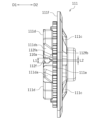
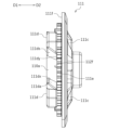
- FIG. 1 is a cross-sectional view showing an outline of the overall configuration of a clutch device according to one embodiment of the present invention with the clutch ON.
- 2 is a perspective view showing the configuration of the center fitting portion side of the plate pressure shown in FIG. 1.
- FIG. 3 is a perspective view showing the configuration of the center fitting portion side of the plate pressure according to the modification of the present invention.
- FIG. 4 is a perspective view showing the configuration of the center fitting portion side of a plate pressure according to another modification of the present invention.
- FIG. 5 is a perspective view showing the configuration of the center fitting portion side of a plate pressure according to another modification of the present invention.
- FIG. 6 is a perspective view showing the configuration of the center fitting portion side of a plate pressure according to another modification of the present invention.
- FIG. 7 is a perspective view showing the configuration of the clutch center shown in FIG. 1.
- FIG. 8 is a plan view showing the configuration of the center fitting portion side of the plate pressure shown in FIG. 1.
- FIG. 9 is a side view showing the configuration of the plate pressure shown in FIG. 1.
- FIG. 10 is a side view showing the configuration of a plate pressure according to another modification of the invention.
- FIG. 11 is a side view showing the configuration of a plate pressure according to another modification of the invention.
- FIG. 12 is a side view showing the configuration of a plate pressure according to another modification of the invention.
- FIG. 13 is a side view showing the configuration of a plate pressure according to another modification of the invention.
- FIG. 14 is a plan view showing the configuration of a plate pressure according to another modification of the invention.
- FIG. 1 is a cross-sectional view showing the outline of the overall configuration of a clutch device 100 according to the present invention.
- the clutch device 100 is a mechanical device for transmitting and interrupting the driving force of an engine (not shown), which is the prime mover of a two-wheeled vehicle (motorcycle), to wheels (not shown), which are driven bodies. It is arranged between a transmission (not shown).
- the clutch device 100 has a clutch outer 101 .
- the clutch outer 101 is a component for holding the input-side rotating plate 105 and for transmitting the driving force from the engine to the input-side rotating plate 105, and is formed by molding an aluminum alloy material into a bottomed cylindrical shape.
- a rotating plate holding portion 101a made of an internal gear-shaped spline is formed in the cylindrically formed portion of the clutch outer 101, and a plurality of (this In the embodiment, five input side rotating plates 105 are spline-fitted and held so as to be displaceable along the axial direction of the clutch outer 101 and integrally rotatable with the clutch outer 101 .
- a connecting hole 101b is formed in the central portion of the left side surface of the clutch outer 101, and a boss portion 103a of an input rotor 103, which will be described later, is slidably fitted into the connecting hole 101b. It is In this case, the input rotor 103 is attached to the clutch outer 101 via a rivet 102a, a side plate 102b, a torque damper 102c, and a separation spring 102d.
- the rivets 102a are a plurality of pin-like parts for regulating the displacement of the input rotor 103 in the axial direction and for arranging the side plate 102b on the plate surface of the input rotor 103.
- the side plate 102 b is a flat annular component for arranging the torque damper 102 c on the plate surface of the input rotor 103 .
- the torque damper 102c is a plurality of coil springs that elastically press the clutch outer 101 against the input rotor 103 in the circumferential direction.
- the separation spring 102d is a flat annular spring that presses the input rotor 103 axially away from the clutch outer 101 .
- the input rotor 103 is a metal gear part that rotates by meshing with a drive gear connected to a drive shaft (not shown) such as a crankshaft that is driven to rotate by a prime mover such as an engine.
- a boss portion 103a is rotatably supported by a shaft 120 via a needle bearing 104.
- the clutch outer 101 rotates integrally with the input rotor 103 independently of the shaft 120 at a position concentric with the shaft 120 .
- Shaft 120 is an example of a driven shaft.
- the input-side rotating plate 105 is a flat plate annular component that is pressed against the output-side rotating plate 106, and is formed by forming a thin plate material made of aluminum into an annular shape.
- the outer peripheral portion of each input-side rotary plate 105 is formed with external teeth that mesh with the internal-toothed splines of the clutch outer 101 .
- Friction materials composed of a plurality of pieces of paper are attached to both side surfaces (front and back surfaces) of the input side rotating plate 105, and oil grooves (not shown) are formed between the friction materials.
- the output-side rotating plate 106 is a flat annular component that is pressed against the input-side rotating plate 105, and is formed by punching a thin plate material made of SPCC (cold-rolled steel plate) into an annular shape.
- the output-side rotating plates 106 are alternately arranged with respect to the plurality of input-side rotating plates 105 inside the clutch outer 101 (five in this embodiment), and are applied to the clutch center 110 and the plate pressure 111 . retained respectively.
- Oil grooves (not shown) having a depth of several micrometers to several tens of micrometers for holding clutch oil are formed on both side surfaces (front and back surfaces) of each of these output-side rotating plates 106, and wear resistance is ensured. Surface hardening treatment is applied for the purpose of improvement.
- each output-side rotary plate 106 an internal gear-shaped plate is spline-fitted to a plate holding portion 110e formed on the clutch center 110 and a plate sub-holding portion 111e formed on the plate pressure 111, respectively.
- a spline is formed respectively.
- the friction material provided on each of the input side rotating plates 105 may of course be provided on each of the output side rotating plates 106 instead of the input side rotating plate 105 .
- Clutch center 110 is a part for accommodating output side rotating plate 106 together with input side rotating plate 105 and transmitting the driving force of the engine to the transmission side, and is formed by forming an aluminum alloy material into a substantially cylindrical shape. It is More specifically, clutch center 110 is mainly configured by integrally forming driven shaft connecting portion 110a, ring-shaped intermediate portion 110b, and plate holding portion 110e.
- the driven shaft connecting portion 110a is a portion to which the plate pressure 111 is fitted and connected to the shaft 120, and extends axially toward the center of the clutch center 110.
- the driven shaft connecting portion 110a is formed in a cylindrical shape.
- the outer peripheral surface of the driven shaft connecting portion 110a is formed into a smooth cylindrical surface on which the center fitting portion 112a of the plate pressure 111 can slide freely in the axial and circumferential directions of the clutch center 110.
- An internal gear-shaped spline is formed along the axial direction on the inner peripheral surface of the driven shaft connecting portion 110a, and the shaft 120 is spline-fitted to this spline. That is, clutch center 110 rotates integrally with shaft 120 at a position concentric with clutch outer 101 and shaft 120 .
- the ring-shaped intermediate portion 110b is a flange-shaped portion formed between the driven shaft connecting portion 110a and the plate holding portion 110e.
- Three cylindrical struts 110c are formed along the circumferential direction of the ring-shaped intermediate portion 110b.
- the three cylindrical struts 110c are cylindrical portions extending in the axial direction of the clutch center 110 in order to support the plate pressure 111, and female threads are formed on the inner periphery thereof. These three cylindrical struts 110 c are evenly formed along the circumferential direction of the clutch center 110 .
- an assist torque which is a force for increasing the pressure contact force between the input-side rotating plate 105 and the output-side rotating plate 106, or a force for separating the input-side rotating plate 105 and the output-side rotating plate 106 early.
- a plurality of pedestal-shaped center-side cam portions 110d having a cam surface formed of an inclined surface constituting an A&S (registered trademark) mechanism that generates a slipper torque that is a force for shifting to a half-clutch state are formed.
- the clutch center 110 has three center-side cam portions 110d, but the number of center-side cam portions 110d is not limited to three. Note that the ring-shaped intermediate portion 110b can be configured without the Assist & Slipper (registered trademark) mechanism.
- the center-side cam portion 110d is located radially outside the driven shaft connecting portion 110a.
- the center-side cam portions 110d are arranged at equal intervals in the circumferential direction of the clutch center 110.
- the center-side cam portion 110d has a center-side assist cam surface 110da and a center-side slipper cam surface 110ds.
- the center-side assist cam surface 110da moves the plate pressure 111 toward the clutch center in order to increase the pressing force (pressure contact force) between the input-side rotating plate 105 and the output-side rotating plate 106 when rotating relative to the plate pressure 111. It is configured to generate a force in the direction of approaching 110 .
- the position of the plate pressure 111 with respect to the clutch center 110 does not change when the force is generated, and the plate pressure 111 does not have to physically approach the clutch center 110 .
- the plate pressure plate 111 may be physically displaced with respect to the clutch center 110 .
- the direction in which the plate pressure 111 approaches the clutch center 110 is defined as a first direction D1 (see FIG. 9).
- the center-side slipper cam surface 110ds is designed to reduce the pressing force (pressure contact force) between the input-side rotary plate 105 and the output-side rotary plate 106 when the plate pressure 111 rotates relative to the plate pressure 111. configured to be separated from
- the direction in which the plate pressure 111 separates from the clutch center 110 is defined as a second direction D2 (see FIG. 9).
- center-side assist cam surface 110da of one center-side cam portion 110d and the center-side slipper cam surface 110ds of the other center-side cam portion 110d are arranged to face each other in the circumferential direction. ing.
- the plate holding portion 110e is a portion that holds a portion of the plurality of output side rotating plates 106 together with the input side rotating plate 105, and extends axially along the outer edge portion of the clutch center 110. As shown in FIG.
- the plate holding portion 110e is formed in a cylindrical shape.
- the plate holding portion 110e has an outer peripheral portion formed of an external gear-shaped spline. It is held so as to be displaceable and integrally rotatable with the clutch center 110 .
- a plate receiving portion 110f is formed at the tip portion on the left side of the drawing of the plate holding portion 110e.
- the plate receiving portion 110f is a portion that receives the output-side rotating plate 106 and the input-side rotating plate 105 pressed by the plate pressure 111 and sandwiches them with the plate pressure 111.
- the distal end portion is formed to protrude radially outward in a flange shape.
- the plate pressure 111 is a component for pressing the input-side rotating plate 105 and bringing the input-side rotating plate 105 and the output-side rotating plate 106 into close contact with each other. It is formed into a substantially disc shape with an outer diameter substantially the same size as the . More specifically, as shown in FIG. 2, the plate pressure 111 mainly includes a center tubular portion 111a, a ring-shaped intermediate portion 111b, and a plate sub-holding portion 111e integrally formed.
- the center tubular portion 111a is a portion that is slidably fitted onto the driven shaft connecting portion 110a and receives a pressing force from the push rod 124 of the shaft 120, and is formed in a cylindrical shape.
- the center tubular portion 111 a accommodates the tip portion 121 of the shaft 120 .
- a center fitting portion 112a and an oil receiving portion 112b are formed in the center cylindrical portion 111a.
- the center fitting portion 112a is fitted onto the driven shaft connecting portion 110a of the clutch center 110 so as to be slidable in the axial direction and the circumferential direction, and is formed in a cylindrical shape with a constant inner diameter.
- the inner diameter of the center fitting portion 112a is formed with a fitting tolerance that allows the flow of clutch oil flowing out from the tip portion of the shaft 120 with respect to the driven shaft connecting portion 110a.
- the center fitting portion 112a has an inner diameter that is 0.1 mm larger than the outer diameter of the driven shaft connecting portion 110a.
- the dimensional tolerance between the inner diameter of the center fitting portion 112a and the outer diameter of the driven shaft connecting portion 110a is appropriately set according to the amount of clutch oil to be circulated, but is preferably 0.1 mm or more and 0.5 mm or less. be.
- the oil receiving portion 112b is a portion that receives the pressing force from the push rod 124 provided on the shaft 120 and receives the clutch oil that flows out from the tip portion of the shaft 120, and is formed in a cylindrical shape with a diameter smaller than that of the center fitting portion 112a. ing.
- a release bearing 112c is fitted to the right end of the oil receiving portion 112b, and an inclined portion 112d is formed between the portion where the release bearing 112c is fitted and the center fitting portion 112a. formed.
- the inclined portion 112d is a portion for guiding the clutch oil flowing out from the tip portion 121 of the shaft 120 to the center fitting portion 112a side, and extends from the side where the release bearing 112c is fitted toward the center fitting portion 112a side. It is formed so as to extend radially outward so as to form a descending slope.
- the inclined portion 112d is appropriately set in accordance with the amount of clutch oil led to the center fitting portion 112a side, and is preferably 1° or more and 5° or less.
- the inclined portion 112d is formed on the entire surface of the portion between the portion where the release bearing 112c is fitted and the center fitting portion 112a.
- An oil passage expansion portion 112e is formed in the center fitting portion 112a and the oil receiving portion 112b.
- the oil passage expansion portion 112e is provided in the center tubular portion 111a so as to expand radially outward.
- the oil passage expansion portion 112e extends radially outward in a portion of the circumferential direction where the center fitting portion 112a is formed.
- the oil passage expansion portion 112e is an example of a recess.
- the oil passage expansion portion 112e is a portion for actively causing the clutch oil present in the oil receiving portion 112b to flow out of the oil receiving portion 112b. It is formed in a groove shape projecting radially outward from the inner peripheral surface. In this case, three oil passage expansion portions 112e are formed at equal intervals along the circumferential direction of the oil receiving portion 112b. As shown in FIG. 8, the oil passage expansion portion 112e is located between the pressure side cam portions 111d, 111d adjacent to each other in the circumferential direction. As shown in FIG.
- the oil passage expansion portion 112e is positioned on the pressure side slipper cam surface 111ds side.
- the clutch oil that has flowed out of the center tubular portion 111a through the oil passage expansion portion 112e is effectively supplied to the pressure side slipper cam surface 111ds as well.
- Each of the three oil passage expansion portions 112e is formed from at least the central portion in the axial direction of the center cylindrical portion 111a to the entire end portion on the clutch center 110 side.
- the oil passage expansion portion 112e is formed so as to extend from the inclined portion 112d side end portion of the portion where the release bearing 112c is fitted to the tip portion (the left end in the drawing) of the center fitting portion 112a. That is, the oil passage expansion portion 112e is formed in a groove shape continuously extending to the inclined portion 112d and the center fitting portion 112a.
- each oil passage expansion portion 112e is formed so as to extend radially outward so as to form a downward slope toward the center fitting portion 112a from the portion where the release bearing 112c is fitted.
- each oil passage expansion portion 112e forms a gap with the outer peripheral portion of the driven shaft connecting portion 110a.
- the gap is appropriately set according to the amount of clutch oil to be circulated, and is preferably 10 times or more, more preferably 100 times or more, the dimensional tolerance between the inner diameter of the center fitting portion 112a and the outer diameter of the driven shaft connecting portion 110a. more preferred.
- An opening 112f is formed in each of these oil passage extensions 112e.
- the circumferential length (groove width) of the center tubular portion 111a in the oil passage expansion portion 112e is the sum of the groove widths of the three oil passage expansion portions 112e. Half or less is preferable.
- the opening 112f is a portion for positively flowing out the clutch oil present in the oil receiving portion 112b to the outside of the oil receiving portion 112b.
- the opening 112f is formed by cutting out a portion of the center cylindrical portion 111a in the circumferential direction.
- the opening 112f is formed by cutting out a portion of the oil passage expansion portion 112e.
- the opening 112f is positioned between the pressure-side cam portions 111d, 111d adjacent in the circumferential direction.
- the opening 112f is located on the side of the pressure-side slipper cam surface 111ds.
- the opening 112f extends from the tip of the center fitting portion 112a (the left end in FIG. 1) to a position overlapping the oil receiving portion 112b in the circumferential direction.
- the end 112x of the opening 112f in the second direction D2 is positioned closer to the first direction D1 than the end 111x of the pressure-side slipper cam surface 111ds in the second direction D2.
- the opening 112f is formed with an opening width equal to or less than half the groove width of the oil passage expanding portion 112e.
- An end 112x of the opening 112f in the second direction D2 is formed in a U shape.
- the ring-shaped intermediate portion 111b is a flange-shaped portion formed between the center tubular portion 111a and the plate sub-holding portion 111e.
- the ring-shaped intermediate portion 111b is formed with three cylindrical housing portions 111c along the circumferential direction.
- the cylindrical accommodating portion 111c is formed in the pressure-side cam portion 111d that constitutes the A&S (registered trademark) mechanism.
- the three cylindrical accommodation portions 111c are portions for accommodating clutch springs 114, which will be described later, and are formed in a circular shape. More specifically, the three cylindrical accommodating portions 111c are formed in concave shapes at equal intervals along the circumferential direction of the plate pressure 111, and the clutch springs 114 are respectively accommodated in the interiors of the concave shapes. ing. In this case, the three cylindrical struts 110c are arranged so as to penetrate between the three cylindrical accommodating portions 111c in the circumferential direction.
- the pressure-side cam portion 111d is formed in a trapezoidal shape having a cam surface made up of an inclined surface that constitutes an A&S (registered trademark) mechanism that slides on the center-side cam portion 110d to generate assist torque or slipper torque. It is In this embodiment, the plate pressure 111 has three pressure-side cam portions 111d, but the number of pressure-side cam portions 111d is not limited to three.
- the pressure-side cam portion 111d is positioned radially outward of the center cylindrical portion 111a.
- the pressure-side cam portions 111 d are arranged at equal intervals in the circumferential direction of the plate pressure 111 .
- the pressure-side cam portion 111d has a pressure-side assist cam surface 111da and a pressure-side slipper cam surface 111ds.
- the pressure-side assist cam surface 111da is configured to be able to contact with the center-side assist cam surface 110da.
- the pressure-side assist cam surface 111da moves the plate pressure 111 toward the clutch center 110 in order to increase the pressing force (pressure contact force) between the input-side rotating plate 105 and the output-side rotating plate 106 when rotating relative to the clutch center 110.
- the pressure-side slipper cam surface 111ds is configured to be able to contact with the center-side slipper cam surface 110ds.
- the pressure-side slipper cam surface 111ds moves the plate pressure 111 toward the clutch center 110 in order to reduce the pressing force (pressure contact force) between the input-side rotating plate 105 and the output-side rotating plate 106 when rotating relative to the clutch center 110.
- the pressure-side assist cam surface 111da of one pressure-side cam portion 111d and the pressure-side slipper cam surface 111ds of the other pressure-side cam portion 111d face each other in the circumferential direction. are placed.
- the plate sub-holding portion 111e is a portion that holds other portions of the plurality of output side rotating plates 106 together with the input side rotating plate 105, and is formed in a cylindrical shape extending in the axial direction of the outer edge portion of the plate pressure 111. ing.
- the plate sub-holding portion 111e has an outer peripheral portion formed of an external gear-shaped spline. It is held in such a state that it can be displaced by the plate pressure and can rotate integrally with the plate pressure 111 .
- a plate pressing portion 111f is formed at the tip of the plate sub-holding portion 111e.
- the plate pressing portion 111f presses the output side rotating plate 106 and the input side rotating plate 105 held by the plate sub-holding portion 111e toward the plate receiving portion 110f to raise the output side rotating plate 106 and the input side rotating plate 105.
- the base portion of the cylindrical plate sub-holding portion 111e is formed so as to protrude radially outward in a flange shape.
- the plate pressure 111 is attached to the clutch center 110 with three mounting bolts 113. More specifically, the plate pressure 111 includes three cylindrical housing portions 111c in which clutch springs 114 are arranged, respectively, and cylindrical struts 110c are respectively disposed between the three cylindrical housing portions 111c in the circumferential direction. A mounting bolt 113 is tightened and fixed to the cylindrical support 110c through a stopper member 115 in a penetrating state.
- the clutch spring 114 is an elastic body arranged in the cylindrical housing portion 111c and exerting an elastic force to press the plate pressure 111 toward the clutch center 110.
- the clutch spring 114 is a coil spring made of spirally wound spring steel. It is composed by Stopper member 115 is a metal member for restricting the amount of displacement of plate pressure 111 in the direction in which plate pressure 111 is separated from clutch center 110, and is formed in a substantially triangular shape in plan view. As a result, the plate pressure 111 is attached to the clutch center 110 so as to be displaceable toward and away from the clutch center 110 .
- the shaft 120 is a component for transmitting the rotational driving force of the clutch center 110 to a driven body (not shown) such as a wheel, and is constructed by forming a steel material into a hollow cylindrical shape.
- the shaft 120 rotatably supports the input rotor 103 via a needle bearing 104 at its one (right side in the drawing) end 121 side, and is spline-fitted with the clutch center 110 .
- a nut 122 is screw-fitted to the tip of the shaft 120 on the right side in the drawing, thereby preventing the clutch center 110 from coming off the shaft 120 .
- the clutch center 110 rotates integrally with the shaft 120.
- the other end (not shown) of shaft 120 is connected to a transmission (not shown) of a two-wheeled vehicle. That is, this shaft 120 corresponds to the driven shaft according to the present invention.
- a hollow portion 123 configured by a through hole extending in the axial direction is formed inside the shaft 120.
- the hollow portion 123 functions as a flow passage for clutch oil to be supplied into the clutch device 100 and includes a push rod 124 .
- Clutch oil flows inside shaft 120 , that is, inside hollow portion 123 .
- the push rod 124 has one end (left side in the drawing) of the shaft 120 connected to a clutch release mechanism (not shown) and pushes a push member 125 at the other end (right side in the drawing).
- the push rod 124 is formed to be narrower than the inner diameter of the hollow portion 123 so that the flowability of the clutch oil is ensured within the hollow portion 123 .
- the clutch release mechanism is a mechanical device that presses the push rod 124 toward the release bearing 112c by operating a clutch operation lever (not shown) by the driver of the self-propelled vehicle on which the clutch device 100 is mounted.
- the push member 125 is a component for pressing the plate pressure 111 via the release bearing 112c, and is configured by forming a metal material into a bar shape.
- the push member 125 has one (right side in the drawing) end connected to a release bearing 112c provided in the plate pressure 111 and the other (left side in the drawing) end of the hollow portion 123 of the shaft 120. 121 is slidably fitted.
- the outer diameter of the portion where the push member 125 is fitted into the hollow portion 123 is formed to be smaller than the inner diameter of the hollow portion 123, so that the flowability of the clutch oil within the hollow portion 123 is ensured.
- the clutch oil flows out into the center tubular portion 111 a of the plate pressure 111 from the outflow portion 121 a of the tip portion 121 of the shaft 120 .
- a predetermined amount of clutch oil (not shown) is filled in the clutch device 100 .
- Clutch oil is mainly supplied to the inside of the clutch device 100 including between the input-side rotating plate 105 and the output-side rotating plate 106 to absorb heat and prevent abrasion of the friction material. That is, this clutch device 100 is a so-called wet multi-plate friction clutch device.
- the clutch release mechanism (not shown) does not press the push member 125 when the driver (not shown) of the vehicle does not operate the clutch operating lever (not shown). Therefore, the plate pressure 111 presses the input side rotating plate 105 by the elastic force of the clutch spring 114 . As a result, the clutch center 110 is rotationally driven in a clutch-on state in which the input-side rotating plate 105 and the output-side rotating plate 106 are pressed against each other and frictionally connected. That is, the rotational driving force of the prime mover is transmitted to clutch center 110 to rotate shaft 120 .
- the clutch oil flowing inside shaft 120 and flowing out from outflow portion 121a of tip end portion 121 of shaft 120 drops or jumps onto oil receiving portion 112b in center cylindrical portion 111a. It adheres (see dashed arrow in FIG. 1).
- the oil receiving portion 112b is formed with an inclined portion 112d that is inclined so that the inner diameter widens toward the center fitting portion 112a. lead.
- the clutch oil flows out of the center tubular portion 111a through the gap between the driven shaft connecting portion 110a and the center fitting portion 112a, and flows to various places inside the clutch device 100.
- the center tubular portion 111a is also formed with an oil passage expansion portion 112e and an opening portion 112f, the clutch oil adhering to the inclined portion 112d more actively flows out of the center tubular portion 111a. and flows to various places inside the clutch device 100 .
- the clutch release mechanism presses the push member 125, so that the plate pressure 111 releases the clutch spring 114. is displaced in the direction away from the clutch center 110 against the elastic force of .
- the clutch center 110 is brought into a clutch-off state in which the frictional connection between the input-side rotating plate 105 and the output-side rotating plate 106 is released, so that the rotational drive is attenuated or stopped. That is, the rotational driving force of the prime mover is cut off from the clutch center 110 .
- the clutch device 100 has the center fitting portion 112a of the plate pressure 111 slidably externally fitted to the driven shaft connecting portion 110a of the clutch center 110.
- An inclined portion 112d extending radially outward toward the center fitting portion 112a is provided on the entire circumference of the inner peripheral surface of the oil receiving portion 112b of the plate pressure 111.
- the clutch device 100 effectively guides the clutch oil flowing out from the shaft 120 as the driven shaft to the sliding portion between the clutch center 110 and the plate pressure 111, thereby causing the clutch oil to flow to the outside of the sliding portion (center cylindrical portion 111a). outside) to lubricate the inside of the clutch device 100 . That is, the clutch device 100 according to the present invention can be made small by providing the sliding portion between the clutch center 110 and the plate pressure 111 at the driven shaft connecting portion 110a near the center of the clutch center 110, thereby reducing the device configuration. can be
- the inclined portion 112d is formed along the entire circumference of the portion between the center fitting portion 112a and the portion of the oil receiving portion 112b where the release bearing 112c is fitted.
- the inclined portion 112d may be formed on at least a portion of the inner peripheral surface of the oil receiving portion 112b so that the inner diameter widens toward the center fitting portion 112a.
- one inclined portion 112d can be formed in the circumferential direction of the oil receiving portion 112b, and one inclined portion 112d can be formed in the axial direction.
- the inclined portion 112d can be intermittently formed in the circumferential direction or the axial direction of the oil receiving portion 112b.
- the center tubular portion 111a is configured by providing the oil passage expansion portion 112e in part of the center fitting portion 112a and the oil receiving portion 112b.
- the center tubular portion 111a can efficiently guide the clutch oil in the center tubular portion 111a to the outside of the center tubular portion 111a.
- the center tubular portion 111a can also be configured without the oil passage expansion portion 112e.
- FIG. 4 shows the plate pressure 111 configured by omitting the oil passage expansion portion 112e and the opening 112f from the center fitting portion 112a.
- FIG. 4 shows the plate pressure 111 configured by omitting the oil passage expansion portion 112e and the opening 112f from the center fitting portion 112a.
- the plate pressure 111 configured by omitting only the oil passage expansion portion 112e from the center fitting portion 112a.
- the center tubular portion 111a may be configured by forming an oil passage expansion portion 112e in one of the center fitting portion 112a and the oil receiving portion 112b.
- the oil passage expanding portion 112e may be connected to the center cylindrical portion 111a of the oil receiving portion 112b. It can be formed in all or part of the direction. Further, when the oil passage expansion portion 112e is formed in the center fitting portion 112a, it is not necessary to be formed so as to be connected to the oil receiving portion 112b. can improve the discharge performance of the clutch oil.
- the center tubular portion 111a is configured by providing the opening portion 112f in a part of the center fitting portion 112a and the oil receiving portion 112b.
- the center tubular portion 111a can efficiently guide the clutch oil in the center tubular portion 111a to the outside of the center tubular portion 111a.
- the center tubular portion 111a can also be configured without the opening 112f, as shown in FIGS. 4 and 6, respectively.
- FIG. 6 shows the plate pressure 111 configured by omitting only the opening 112f from the center fitting portion 112a.
- the center tubular portion 111a can also be configured by forming an opening 112f in one of the center fitting portion 112a and the oil receiving portion 112b. Further, when the opening 112f is formed in the center fitting portion 112a or the oil receiving portion 112b, it can be formed in all or part of the center cylindrical portion 111a in the axial direction. Further, when the opening 112f is formed in the center fitting portion 112a, the opening 112f does not necessarily have to be formed so as to be connected to the oil receiving portion 112b. It is possible to improve oil dischargeability.
- the opening 112f is formed at a position facing the central portion of the plate holding portion 110e in the axial direction.
- the clutch oil in the center tubular portion 111a is supplied to the central portion outside the center tubular portion 111a where the input side rotary plate 105 and the output side rotary plate 106 are arranged side by side via the opening 112f.
- the entire input-side rotating plate 105 and output-side rotating plate 106 can be efficiently lubricated.
- the opening 112f may be formed at a position other than the central portion in the axial direction of the plate holding portion 110e (a position offset from the central portion).
- the center fitting portion 112a is formed in a cylindrical shape after increasing the diameter stepwise with respect to the boundary portion with the oil receiving portion 112b (see dashed circle D in FIG. 1).
- the center cylindrical portion 111a forms an oil reservoir for clutch oil in the stepped portion at the boundary between the center fitting portion 112a and the oil receiving portion 112b, thereby preventing the gap between the driven shaft connecting portion 110a and the center fitting portion 112a. It is possible to make it easier to guide the clutch oil between them.
- the center fitting portion 112a may be formed in a cylindrical shape directly at the boundary portion with the oil receiving portion 112b.
- the oil passage expansion portion 112e is positioned on the pressure side slipper cam surface 111ds side, but the present invention is not limited to this.
- the oil passage expansion portion 112e may be located on the side of the pressure-side assist cam surface 111da.
- the oil passage expansion portion 112e may be provided in the center between the pressure-side slipper cam surface 111ds and the pressure-side assist cam surface 111da in the circumferential direction.
- the opening 112f is located on the pressure side slipper cam surface 111ds side, but it is not limited to this.
- the opening 112f may be located on the side of the pressure-side assist cam surface 111da.
- the opening 112f may be provided in the center between the pressure-side slipper cam surface 111ds and the pressure-side assist cam surface 111da in the circumferential direction.
- the end 112x of the opening 112f in the second direction D2 is positioned closer to the first direction D1 than the end 111x of the pressure-side slipper cam surface 111ds in the second direction D2. , but not limited to.
- the end 112x of the opening 112f in the second direction D2 is located on the second direction D2 side of the end 111x of the pressure-side slipper cam surface 111ds in the second direction D2. You may have
- the opening width of the opening 112f in the circumferential direction is constant in the above embodiment, it is not limited to this.
- the opening 112f includes a first portion 112fa having a first length L1 in the circumferential direction, and a first portion 112fa located on the second direction D2 side of the first portion 112fa. and a second portion 112fb whose directional length is a second length L2 that is less than the first length L1.
- the opening 112f is formed by cutting out a portion of the center tubular portion 111a between the pressure side cam portions 111d, 111d adjacent in the circumferential direction, but the present invention is not limited to this.
- the opening 112f may be formed by cutting out the entire pressure-side cam portions 111d, 111d adjacent in the circumferential direction of the center tubular portion 111a. That is, as shown in FIG. 14, the direction from one pressure side cam portion 111d to the other pressure side cam portion 111d in the circumferential direction is the first circumferential direction S1, and from the other pressure side cam portion 111d to the one pressure side.
- the opening portion 112f extends from the end portion 111dx of the pressure-side assist cam surface 111da on the first circumferential direction S1 side to the second circumferential direction S1 of the pressure-side slipper cam surface 111ds. It may be formed up to the end portion 111dy on the side of the circumferential direction S2.
- the center fitting portion 112a is directly slidably fitted onto the driven shaft connecting portion 110a, but the center fitting portion 112a is indirectly driven by another member such as a sleeve. It may be fitted onto the shaft connecting portion 110a.
- Plate pressure 111a Center tubular portion 111b... Ring-shaped intermediate portion 111c... Cylindrical accommodating portion 111d... Pressure-side cam portion 111da... Pressure-side assist cam surface 111ds... Pressure-side slipper cam surface 111e... plate sub-holding portion, 111f... plate pushing portion, 112a...Center fitting portion, 112b...Oil receiving portion, 112c...Release bearing, 112d...Inclined portion, 112e... Oil passage expansion portion (recessed portion), 112f...Opening portion, 113... Mounting bolt, 114... Clutch spring, 115... Stopper member, DESCRIPTION OF SYMBOLS 120... Shaft (driven shaft), 121... Tip part, 121a... Outflow part, 122... Nut, 123... Hollow part, 124... Push rod, 125... Push member.
Abstract
This clutch device 100 comprises a clutch center 110 holding an output-side rotating plate 106 disposed facing an input-side rotating plate 105, and a plate presser 111 that presses the input-side rotating plate 105 or the output-side rotating plate 106. The clutch center 110 has a driven shaft coupling part 110a to which a tip 121 of a shaft 120 is coupled. The plate presser 111 has a center cylindrical part 111a in which are formed a center fitting portion 112a externally fitting to the driven shaft coupling part 110a so as to be freely slidable, and an oil receiving portion 112b that is adjacent to the center fitting portion 112a and receives clutch oil flowing out from the tip 121 of the shaft 120.
Description
本発明は、原動機によって回転駆動する原動軸の回転駆動力を被動体を駆動させる従動軸に伝達および遮断するクラッチ装置およびそれを備えた自動二輪車に関する。
The present invention relates to a clutch device that transmits and interrupts the rotational driving force of a drive shaft that is rotationally driven by a prime mover to a driven shaft that drives a driven body, and a motorcycle equipped with the same.
従来から、二輪自動車(自動二輪車)や四輪自動車などの車両においては、エンジンなどの原動機と車輪などの被動体との間に配置されて原動機の回転駆動力を被動体に伝達または遮断するためにクラッチ装置が用いられている。一般に、クラッチ装置は、原動機の回転駆動力によって回転する複数の入力側回転板と被動体に連結された複数の出力側回転板とを互いに対向配置するとともに、これらの入力側回転板と出力側回転板とを密着および離隔させることにより回転駆動力の伝達または遮断を任意に行なうことができる。
Conventionally, in vehicles such as two-wheeled vehicles (motorcycles) and four-wheeled vehicles, a motor is placed between a prime mover such as an engine and a driven body such as a wheel to transmit or block the rotational driving force of the prime mover to the driven body. A clutch device is used in In general, a clutch device has a plurality of input-side rotating plates that are rotated by the rotational driving force of a prime mover and a plurality of output-side rotating plates that are connected to a driven body. It is possible to arbitrarily transmit or block the rotational driving force by bringing the rotary plate into close contact with or away from it.
例えば、下記特許文献1には、被動体にシャフトを介して連結されて前記出力側回転板を保持するセンタークラッチと、このセンタークラッチが保持する出力側回転板を押圧するプレッシャークラッチとがセンタークラッチにおけるセンター側嵌合部の内周部に軸方向に摺動自在に嵌合するクラッチ装置が開示されている。この場合、センター側嵌合部は、シャフトの先端部から流出するクラッチオイルのクラッチ装置内での拡散性を考慮してクラッチ装置における径方向外側位置となる出力側回転板および入力側回転板の内周部近傍に形成されている。
For example, Patent Document 1 below describes a center clutch that is connected to a driven body via a shaft and holds the output-side rotating plate, and a pressure clutch that presses the output-side rotating plate held by the center clutch. A clutch device is disclosed which is axially slidably fitted to the inner peripheral portion of the center side fitting portion of the. In this case, the center-side fitting portion is located between the output-side rotating plate and the input-side rotating plate, which are radially outer positions in the clutch device, in consideration of the diffusibility in the clutch device of the clutch oil flowing out from the tip of the shaft. It is formed near the inner periphery.
しかしながら、上記特許文献1に記載したクラッチ装置においては、センター側嵌合部がクラッチ装置における径方向外側位置に形成されているため、摺動部分が大径化して摺動抵抗が大きくクラッチ装置の小型化が困難であるという問題がある。
However, in the clutch device described in Patent Document 1, since the center-side fitting portion is formed at a radially outer position in the clutch device, the sliding portion has a large diameter and a large sliding resistance, resulting in a large sliding resistance of the clutch device. There is a problem that miniaturization is difficult.
本発明は上記問題に対処するためなされたもので、その目的は、装置構成を小型化することができるクラッチ装置およびそれを備えた自動二輪車を提供することにある。
The present invention has been made to address the above problem, and its object is to provide a clutch device that can be downsized in device configuration and a motorcycle equipped with the same.
上記目的を達成するため、本発明の特徴は、原動軸の回転駆動力を従動軸に伝達または遮断するクラッチ装置において、原動軸の回転駆動によって回転駆動する入力側回転板に対向配置される出力側回転板を保持するプレート保持部を有して従動軸とともに回転駆動するクラッチセンタと、クラッチセンタに対して接近または離隔可能かつ相対回転可能な状態で対向配置されて入力側回転板または出力側回転板を押圧するプレートプレッシャとを備え、従動軸は、先端部に軸内を流動したクラッチオイルが流出する流出部を有し、クラッチセンタは、従動軸における先端部が連結される従動軸連結部を有し、プレートプレッシャは、従動軸連結部に摺動自在に外嵌するセンター嵌合部およびこのセンター嵌合部に隣接して従動軸における流出部から流出したクラッチオイルを受ける筒状のオイル受け部がそれぞれ形成されたセンター筒状部を有することにある。
In order to achieve the above object, the present invention is characterized in that, in a clutch device for transmitting or interrupting the rotational driving force of a driving shaft to a driven shaft, an output is disposed facing an input-side rotating plate that is rotationally driven by the rotational driving of the driving shaft. A clutch center that has a plate holding portion that holds a side rotating plate and is rotationally driven together with a driven shaft, and an input side rotating plate or an output side that are disposed facing each other in a state that can be approached or separated from the clutch center and relatively rotatable. a plate pressure for pressing the rotating plate; the driven shaft has an outflow portion at the tip for the clutch oil that has flowed in the shaft to flow out; and the clutch center is a driven shaft connection to which the tip of the driven shaft is connected. The plate pressure has a center fitting portion slidably fitted on the driven shaft connecting portion, and a cylindrical portion adjacent to the center fitting portion for receiving the clutch oil flowing out from the outflow portion of the driven shaft. It is to have a center tubular portion in which the oil receiving portion is formed respectively.
このように構成した本発明の特徴によれば、クラッチ装置は、プレートプレッシャのセンター筒状部のセンター嵌合部がクラッチセンタの従動軸連結部に摺動自在に外嵌し、センター筒状部のオイル受け部が従動軸の流出部から流出したクラッチオイルを受ける。これにより、従動軸から流出するクラッチオイルをクラッチセンタとプレートプレッシャとの摺動部に効果的に導いて同摺動部の外側(センター筒状部の外部)に流出させてクラッチ装置内を潤滑することができる。すなわち、本発明に係るクラッチ装置は、クラッチセンタとプレートプレッシャとの摺動部分をクラッチセンタにおける中心部に近い従動軸連結部に設けて小さく構成することができ装置構成を小型化することができる。
According to the characteristic of the present invention configured as described above, in the clutch device, the center fitting portion of the center tubular portion of the plate pressure is slidably externally fitted to the driven shaft connecting portion of the clutch center, and the center tubular portion receives the clutch oil flowing out from the outflow part of the driven shaft. As a result, the clutch oil flowing out from the driven shaft is effectively guided to the sliding portion between the clutch center and the plate pressure, and flowed outside the sliding portion (outside the center tubular portion) to lubricate the inside of the clutch device. can do. That is, the clutch device according to the present invention can be made small by providing the sliding portion between the clutch center and the plate pressure at the driven shaft connecting portion near the center of the clutch center, and the device configuration can be made compact. .
また、本発明の他の特徴は、前記オイル受け部は、内周面の少なくとも一部に前記センター嵌合部に向かって径方向外側に広がる傾斜部を備えることにある。
Another feature of the present invention is that the oil receiving portion has an inclined portion extending radially outward toward the center fitting portion on at least a part of the inner peripheral surface.
このように構成した本発明の特徴によれば、従動軸から流出するクラッチオイルを効果的にセンター嵌合部に向けて導くことができるため、クラッチセンタとプレートプレッシャとの摺動部により効果的に導いて同摺動部の外側(センター筒状部の外部)に流出させてクラッチ装置内を潤滑することができる。
According to the features of the present invention configured as described above, since the clutch oil flowing out from the driven shaft can be effectively guided toward the center fitting portion, the sliding portion between the clutch center and the plate pressure can be more effectively operated. and flows out to the outside of the sliding portion (the outside of the center tubular portion) to lubricate the inside of the clutch device.
また、本発明の他の特徴は、前記クラッチ装置において、センター筒状部は、センター嵌合部が形成された周方向の一部に径方向外側に広がって従動軸連結部の外周部との間に隙間を形成する油路拡張部を有することにある。
Another feature of the present invention is that in the clutch device, the center cylindrical portion spreads radially outward in a part of the circumference where the center fitting portion is formed so as to be in contact with the outer peripheral portion of the driven shaft connecting portion. It is to have an oil passage expansion part forming a gap therebetween.
このように構成した本発明の特徴によれば、クラッチ装置は、センター筒状部におけるセンター嵌合部が形成された周方向の一部に径方向外側に広がって従動軸連結部の外周部との間に隙間を形成する油路拡張部を有しているため、センター筒状部内のクラッチオイルを油路拡張部を介して効果的にセンター筒状部外に導くことができる。なお、油路拡張部によって従動軸連結部との間に形成される隙間は、従動軸連結部とセンター嵌合部との間に形成される隙間より大きな隙間であることは当然である。
According to the characteristic of the present invention configured as described above, the clutch device spreads radially outward in a portion of the circumferential direction where the center fitting portion of the center cylindrical portion is formed, and is connected to the outer peripheral portion of the driven shaft connecting portion. Since there is an oil passage expansion portion forming a gap therebetween, the clutch oil in the center tubular portion can be effectively led out of the center tubular portion via the oil passage expansion portion. It is a matter of course that the gap formed between the oil passage expansion portion and the driven shaft connecting portion is larger than the gap formed between the driven shaft connecting portion and the center fitting portion.
また、本発明の他の特徴は、前記クラッチ装置において、油路拡張部は、センター嵌合部からオイル受け部まで延びて形成されていることにある。
Another feature of the present invention is that, in the clutch device, the oil passage expansion portion is formed to extend from the center fitting portion to the oil receiving portion.
このように構成した本発明の他の特徴によれば、クラッチ装置は、油路拡張部がセンター嵌合部からオイル受け部に達してまたはオイル受け部にまで入り込む程度に延びて形成されているため、センター筒状部内のクラッチオイルを油路拡張部を介して効果的にセンター筒状部外に導くことができる。
According to another feature of the present invention configured as described above, the clutch device is formed such that the oil passage expansion portion extends from the center fitting portion to the extent that it reaches the oil receiving portion or enters the oil receiving portion. Therefore, the clutch oil in the center tubular portion can be effectively led out of the center tubular portion through the oil passage expansion portion.
また、本発明の他の特徴は、前記クラッチ装置において、センター筒状部は、センター嵌合部が形成された周方向の一部にこの一部が切り欠かれた開口部を有することにある。
Another feature of the present invention is that, in the clutch device, the center cylindrical portion has an opening partly cut away in a part of the circumferential direction where the center fitting portion is formed. .
このように構成した本発明の他の特徴によれば、クラッチ装置は、センター筒状部におけるセンター嵌合部が形成された周方向の一部にこの一部が切り欠かれた開口部を有しているため、センター筒状部内のクラッチオイルを開口部を介して効果的にセンター筒状部外に導くことができる。
According to another feature of the present invention configured as described above, the clutch device has an opening formed by notching a portion of the center cylindrical portion in the circumferential direction where the center fitting portion is formed. Therefore, the clutch oil in the center tubular portion can be effectively led out of the center tubular portion through the opening.
また、本発明の他の特徴は、前記クラッチ装置において、開口部は、プレート保持部の軸方向の中央部に対向する位置に形成されていることにある。
Another feature of the present invention is that, in the clutch device, the opening is formed at a position facing the central portion of the plate holding portion in the axial direction.
このように構成した本発明の他の特徴によれば、クラッチ装置は、開口部がプレート保持部の軸方向の中央部に対向する位置に形成されているため、センター筒状部内のクラッチオイルを開口部を介して効果的にセンター筒状部外におけるプレート保持部の軸方向の中央部に導くことができる。すなわち、クラッチ装置は、センター筒状部内のクラッチオイルを入力側回転板および出力側回転板が並んで配置された中央部に供給してこれらの入力側回転板および出力側回転板の全体に効率的にクラッチオイルを供給することができる。なお、開口部の形成位置となるプレート保持部の軸方向の中央部とは、厳密な意味での中央部ではなく厳密な意味での中央部の付近を含むものである。
According to another feature of the present invention configured as described above, the opening of the clutch device is formed at a position facing the central portion of the plate holding portion in the axial direction. Through the opening, it can be effectively guided to the axially central portion of the plate holding portion outside the center cylindrical portion. That is, the clutch device supplies the clutch oil in the center tubular portion to the central portion where the input side rotating plate and the output side rotating plate are arranged side by side, and the entirety of these input side rotating plate and the output side rotating plate is efficiently supplied. clutch oil can be supplied. Note that the central portion in the axial direction of the plate holding portion where the opening is formed includes not the central portion in the strict sense but the vicinity of the central portion in the strict sense.
また、本発明の他の特徴は、前記クラッチ装置において、開口部は、センター嵌合部からオイル受け部まで延びて形成されていることにある。
Another feature of the present invention is that, in the clutch device, the opening is formed extending from the center fitting portion to the oil receiving portion.
このように構成した本発明の他の特徴によれば、クラッチ装置は、開口部がセンター嵌合部からオイル受け部に達してまたはオイル受け部にまで入り込む程度にまで延びて形成されているため、センター筒状部内のクラッチオイルを開口部を介して効果的にセンター筒状部外に導くことができる。
According to another feature of the present invention constructed as described above, the clutch device is formed so that the opening extends from the center fitting portion to the extent that it reaches the oil receiving portion or enters the oil receiving portion. , the clutch oil in the center tubular portion can be effectively led out of the center tubular portion through the opening.
ここで、入力側回転板および出力側回転板が圧接する際には両回転板にクラッチオイルが十分に供給されていると、両回転板の摩耗を低減させることができる。このため、上記特許文献1のクラッチ装置のように、シャフトの先端部からクラッチオイルが流出する構造では、クラッチオイルを入力側回転板および出力側回転板により効果的に導くことが望まれている。
Here, when the input-side rotating plate and the output-side rotating plate are in pressure contact with each other, if sufficient clutch oil is supplied to both rotating plates, wear of both rotating plates can be reduced. For this reason, in a structure in which the clutch oil flows out from the tip of the shaft as in the clutch device of Patent Document 1, it is desired that the clutch oil is effectively guided by the input-side rotating plate and the output-side rotating plate. .
本発明は上記問題に対処するためなされたもので、その目的は、入力側回転板および出力側回転板により多くのクラッチオイルを供給することができるクラッチ装置を提供することにある。
The present invention has been made to address the above problem, and its object is to provide a clutch device capable of supplying more clutch oil to the input-side rotating plate and the output-side rotating plate.
また、本発明の特徴は、原動軸の回転駆動力を従動軸に伝達または遮断するクラッチ装置において、前記原動軸の回転駆動によって回転駆動する入力側回転板に対向配置される出力側回転板を保持するプレート保持部を有して前記従動軸とともに回転駆動するクラッチセンタと、前記クラッチセンタに対して接近または離隔可能かつ相対回転可能な状態で対向配置されて前記入力側回転板または前記出力側回転板を押圧するプレートプレッシャとを備え、前記従動軸は、先端部に軸内を流動したクラッチオイルが流出する流出部を有し、前記クラッチセンタは、前記従動軸における前記先端部が連結される従動軸連結部を有し、前記プレートプレッシャは、前記従動軸連結部に摺動自在に外嵌するセンター嵌合部、および、前記センター嵌合部が形成された周方向の一部に径方向外側に広がって前記従動軸連結部の外周部との間に隙間を形成しかつ前記流出部から流出した前記クラッチオイルが流れる凹部、を有するセンター筒状部を備えていることにある。
Further, the present invention is characterized in that, in a clutch device for transmitting or interrupting the rotational driving force of a driving shaft to a driven shaft, an output side rotating plate arranged opposite to an input side rotating plate rotationally driven by the rotational driving of the driving shaft is provided. A clutch center having a plate holding portion for holding and rotationally driven together with the driven shaft; a plate pressure for pressing the rotating plate; the driven shaft has an outflow portion at a tip portion through which clutch oil that has flowed in the shaft flows out; and the clutch center is connected to the tip portion of the driven shaft. The plate pressure has a center fitting portion that is slidably fitted onto the driven shaft coupling portion, and a part of the circumference in which the center fitting portion is formed. There is provided a center cylindrical portion having a concave portion that spreads outward in the direction to form a gap with the outer peripheral portion of the driven shaft connecting portion and through which the clutch oil that has flowed out from the outflow portion flows.
このように構成した本発明の特徴によれば、従動軸の流出部から流出したクラッチオイルは凹部を流れる。ここで、凹部は、従動軸連結部の外周部との間に隙間を形成するため、凹部を流れるクラッチオイルはより効果的にセンター筒状部の外部に流出し、入力側回転板および出力側回転板により多くのクラッチオイルを供給することができる。
According to the features of the present invention configured in this manner, the clutch oil flowing out from the outflow portion of the driven shaft flows through the recess. Here, since the recess forms a gap with the outer peripheral portion of the driven shaft connecting portion, the clutch oil flowing through the recess more effectively flows out of the center cylindrical portion, More clutch oil can be supplied to the rotating plate.
また、本発明の他の特徴は、前記クラッチセンタは、前記従動軸連結部の径方向外側に位置し、かつ、前記プレートプレッシャに対して相対回転した際に、前記入力側回転板と前記出力側回転板との押圧力を増加させるために前記プレートプレッシャを前記クラッチセンタに接近させる方向の力を発生させるセンタ側アシストカム面、および、前記入力側回転板と前記出力側回転板との押圧力を減少させるために前記プレートプレッシャを前記クラッチセンタから離隔させるセンタ側スリッパーカム面を有する複数のセンタ側カム部を有し、前記プレートプレッシャは、前記センター筒状部の径方向外側に位置し、かつ、前記クラッチセンタに対して相対回転した際に、前記センタ側アシストカム面と接触可能に構成されかつ前記入力側回転板と前記出力側回転板との押圧力を増加させるために前記プレートプレッシャを前記クラッチセンタに接近させる方向の力を発生させるプレッシャ側アシストカム面、および、前記センタ側スリッパーカム面と接触可能に構成されかつ前記入力側回転板と前記出力側回転板との押圧力を減少させるために前記プレートプレッシャを前記クラッチセンタから離隔させるプレッシャ側スリッパーカム面を有する複数のプレッシャ側カム部を有し、前記凹部は、周方向に関して隣り合う前記プレッシャ側カム部の間に位置することにある。
Another feature of the present invention is that the clutch center is located radially outside of the driven shaft connecting portion, and when the clutch center rotates relative to the plate pressure, the input-side rotating plate and the output-side rotating plate rotate. a center-side assist cam surface that generates a force in a direction to bring the plate pressure closer to the clutch center in order to increase the pressing force with the side rotating plate; a plurality of center-side cam portions having center-side slipper cam surfaces that separate the plate pressure from the clutch center to reduce pressure, the plate pressure being positioned radially outward of the center tubular portion; In addition, the plate pressure is configured to be capable of coming into contact with the center-side assist cam surface when rotated relative to the clutch center, and increases the pressing force between the input-side rotating plate and the output-side rotating plate. to the clutch center, and the center-side slipper cam surface to reduce the pressing force between the input-side rotating plate and the output-side rotating plate. a plurality of pressure-side cam portions having pressure-side slipper cam surfaces for separating the plate pressure from the clutch center, and the recesses are positioned between the pressure-side cam portions adjacent in the circumferential direction. be.
このように構成した本発明の特徴によれば、凹部は、周方向に関して隣り合うプレッシャ側カム部の間に位置する。これにより、凹部を流れてセンター筒状部の外部に流出したクラッチオイルは入力側回転板および出力側回転板により流れやすくなる。
According to the feature of the present invention configured in this manner, the recess is positioned between the pressure-side cam portions that are adjacent in the circumferential direction. As a result, the clutch oil that has flowed through the concave portion and flowed out of the center tubular portion is made easier to flow through the input-side rotating plate and the output-side rotating plate.
また、本発明の他の特徴は、周方向に関して隣り合う前記プレッシャ側カム部において、一方の前記プレッシャ側カム部の前記プレッシャ側アシストカム面と他方の前記プレッシャ側カム部の前記プレッシャ側スリッパーカム面とが周方向に対向して配置されているとき、前記凹部は、前記プレッシャ側アシストカム面側に位置することにある。
Another feature of the present invention is that, in the pressure-side cam portions that are adjacent in the circumferential direction, the pressure-side assist cam surface of one of the pressure-side cam portions and the pressure-side slipper cam surface of the other pressure-side cam portion are provided. are arranged facing each other in the circumferential direction, the recess is located on the pressure-side assist cam surface side.
このように構成した本発明の特徴によれば、凹部は、プレッシャ側アシストカム面側に位置する。これにより、センター筒状部の外部に流出したクラッチオイルは、プレッシャ側アシストカム面にも効果的に供給されるため、プレッシャ側アシストカム面およびセンタ側アシストカム面の摩耗を低減することができる。
According to the feature of the present invention configured in this manner, the recess is positioned on the pressure-side assist cam surface side. As a result, the clutch oil that has flowed out of the center cylindrical portion is effectively supplied to the pressure-side assist cam surface as well, so that wear on the pressure-side assist cam surface and the center-side assist cam surface can be reduced. .
また、本発明の他の特徴は、周方向に関して隣り合う前記プレッシャ側カム部において、一方の前記プレッシャ側カム部の前記プレッシャ側アシストカム面と他方の前記プレッシャ側カム部の前記プレッシャ側スリッパーカム面とが周方向に対向して配置されているとき、前記凹部は、前記プレッシャ側スリッパーカム面側に位置することにある。
Another feature of the present invention is that, in the pressure-side cam portions that are adjacent in the circumferential direction, the pressure-side assist cam surface of one of the pressure-side cam portions and the pressure-side slipper cam surface of the other pressure-side cam portion are provided. are arranged facing each other in the circumferential direction, the recess is located on the side of the pressure-side slipper cam surface.
このように構成した本発明の特徴によれば、凹部は、プレッシャ側スリッパーカム面側に位置する。プレッシャ側スリッパーカム面側に加わる応力は、プレッシャアシストカム面に加わる応力より小さいため、プレッシャ側スリッパーカム面側に凹部を設けることにより、センター筒状部の強度を十分に保持しつつセンター筒状部の外部にクラッチオイルを流すことができる。
According to the feature of the present invention configured in this manner, the recess is located on the pressure side slipper cam surface side. Since the stress applied to the pressure-side slipper cam surface is smaller than the stress applied to the pressure-assist cam surface, by providing a concave portion on the pressure-side slipper cam surface side, the strength of the center tubular portion can be maintained while maintaining the strength of the center tubular portion. Clutch oil can flow outside.
また、本発明の他の特徴は、前記凹部は、前記センター筒状部の軸方向の少なくとも中央部から前記クラッチセンタ側の端部の全体に亘って形成されていることにある。
Another feature of the present invention is that the recess is formed from at least the central portion in the axial direction of the center tubular portion to the entire end portion on the clutch center side.
このように構成した本発明の特徴によれば、従動軸の流出部から流出したクラッチオイルをより確実にセンター筒状部の外部に流出させ、入力側回転板および出力側回転板により多くのクラッチオイルを供給することができる。
According to the features of the present invention configured in this way, the clutch oil that has flowed out of the outflow portion of the driven shaft can be more reliably flowed out of the center cylindrical portion, and more clutches can be produced by the input-side rotating plate and the output-side rotating plate. Can supply oil.
また、本発明の他の特徴は、原動軸の回転駆動力を従動軸に伝達または遮断するクラッチ装置において、前記原動軸の回転駆動によって回転駆動する入力側回転板に対向配置される出力側回転板を保持するプレート保持部を有して前記従動軸とともに回転駆動するクラッチセンタと、前記クラッチセンタに対して接近または離隔可能かつ相対回転可能な状態で対向配置されて前記入力側回転板または前記出力側回転板を押圧するプレートプレッシャとを備え、前記従動軸は、先端部に軸内を流動したクラッチオイルが流出する流出部を有し、前記クラッチセンタは、前記従動軸における前記先端部が連結される従動軸連結部と、前記従動軸連結部の径方向外側に位置し、かつ、前記プレートプレッシャに対して相対回転した際に、前記入力側回転板と前記出力側回転板との押圧力を増加させるために前記プレートプレッシャを前記クラッチセンタに接近させる方向の力を発生させるセンタ側アシストカム面、および、前記入力側回転板と前記出力側回転板との押圧力を減少させるために前記プレートプレッシャを前記クラッチセンタから離隔させるセンタ側スリッパーカム面を有する複数のセンタ側カム部と、を有し、前記プレートプレッシャは、前記従動軸の前記先端部を収容するセンター筒状部と、前記センター筒状部の径方向外側に位置し、かつ、前記クラッチセンタに対して相対回転した際に、前記センタ側アシストカム面と接触可能に構成されかつ前記入力側回転板と前記出力側回転板との押圧力を増加させるために前記プレートプレッシャを前記クラッチセンタに接近させる方向の力を発生させるプレッシャ側アシストカム面、および、前記センタ側スリッパーカム面と接触可能に構成されかつ前記入力側回転板と前記出力側回転板との押圧力を減少させるために前記プレートプレッシャを前記クラッチセンタから離隔させるプレッシャ側スリッパーカム面を有する複数のプレッシャ側カム部と、周方向に関して隣り合う前記プレッシャ側カム部の間かつ前記径方向外側に広がるように前記センター筒状部に設けられ、前記流出部から流出した前記クラッチオイルが流れる凹部と、を有することにある。
Another feature of the present invention is a clutch device for transmitting or interrupting the rotational driving force of a driving shaft to a driven shaft, in which an output-side rotating plate is arranged opposite to an input-side rotating plate that is rotationally driven by the rotational driving of the driving shaft. A clutch center having a plate holding portion for holding a plate and rotationally driven together with the driven shaft; a plate pressure that presses the output-side rotating plate; the driven shaft has an outflow portion at a tip portion through which clutch oil that has flowed in the shaft flows out; and the clutch center has the tip portion of the driven shaft a driven shaft connecting portion to be connected; In order to increase the pressure, the center-side assist cam surface generates a force in the direction to bring the plate pressure closer to the clutch center, and to reduce the pressing force between the input-side rotating plate and the output-side rotating plate. a plurality of center-side cam portions having a center-side slipper cam surface that separates the plate pressure from the clutch center; the plate pressure includes a center cylindrical portion that accommodates the tip portion of the driven shaft; The input-side rotating plate and the output-side rotating plate are positioned radially outwardly of the center tubular portion, and are configured to be able to contact with the center-side assist cam surface when rotated relative to the clutch center. a pressure-side assist cam surface that generates a force in a direction to bring the plate pressure closer to the clutch center in order to increase the pressing force of the input-side rotating plate, and the input-side rotating plate configured to be in contact with the center-side slipper cam surface. a plurality of pressure-side cam portions having pressure-side slipper cam surfaces separating the plate pressure from the clutch center in order to reduce the pressing force between the plate pressure and the output-side rotating plate; and the pressure-side cam portions adjacent in the circumferential direction. and a concave portion provided in the center tubular portion so as to spread between and radially outward, and through which the clutch oil flowing out from the outflow portion flows.
このように構成した本発明の特徴によれば、プレートプレッシャの凹部は、周方向に関して隣り合うプレッシャ側カム部の間かつ従動軸と対向する位置に位置するようにセンター筒状部に設けられている。これにより、凹部を流れるクラッチオイルはより効果的にセンター筒状部の外部に流出し、入力側回転板および出力側回転板により多くのクラッチオイルを供給することができる。
According to the feature of the present invention configured as described above, the concave portion of the plate pressure is provided in the center cylindrical portion so as to be positioned between the pressure-side cam portions adjacent in the circumferential direction and at a position facing the driven shaft. there is As a result, the clutch oil flowing through the recess can more effectively flow out of the center tubular portion, and more clutch oil can be supplied to the input-side rotating plate and the output-side rotating plate.
また、本発明の他の特徴は、周方向に関して隣り合う前記プレッシャ側カム部において、一方の前記プレッシャ側カム部の前記プレッシャ側アシストカム面と他方の前記プレッシャ側カム部の前記プレッシャ側スリッパーカム面とが周方向に対向して配置されているとき、前記凹部は、前記プレッシャ側アシストカム面側に位置することにある。
Another feature of the present invention is that, in the pressure-side cam portions that are adjacent in the circumferential direction, the pressure-side assist cam surface of one of the pressure-side cam portions and the pressure-side slipper cam surface of the other pressure-side cam portion are provided. are arranged facing each other in the circumferential direction, the recess is located on the pressure-side assist cam surface side.
このように構成した本発明の特徴によれば、凹部は、プレッシャ側アシストカム面側に位置する。これにより、センター筒状部の外部に流出したクラッチオイルは、プレッシャ側アシストカム面にも効果的に供給されるため、プレッシャ側アシストカム面およびセンタ側アシストカム面の摩耗を低減することができる。
According to the feature of the present invention configured in this manner, the recess is positioned on the pressure-side assist cam surface side. As a result, the clutch oil that has flowed out of the center cylindrical portion is effectively supplied to the pressure-side assist cam surface as well, so that wear on the pressure-side assist cam surface and the center-side assist cam surface can be reduced. .
また、本発明の他の特徴は、周方向に関して隣り合う前記プレッシャ側カム部において、一方の前記プレッシャ側カム部の前記プレッシャ側アシストカム面と他方の前記プレッシャ側カム部の前記プレッシャ側スリッパーカム面とが周方向に対向して配置されているとき、前記凹部は、前記プレッシャ側スリッパーカム面側に位置することにある。
Another feature of the present invention is that, in the pressure-side cam portions that are adjacent in the circumferential direction, the pressure-side assist cam surface of one of the pressure-side cam portions and the pressure-side slipper cam surface of the other pressure-side cam portion are provided. are arranged facing each other in the circumferential direction, the recess is located on the side of the pressure-side slipper cam surface.
このように構成した本発明の特徴によれば、凹部は、プレッシャ側スリッパーカム面側に位置する。プレッシャ側スリッパーカム面側に加わる応力は、プレッシャアシストカム面に加わる応力より小さいため、プレッシャ側スリッパーカム面側に凹部を設けることにより、センター筒状部の強度を十分に保持しつつセンター筒状部の外部にクラッチオイルを流すことができる。
According to the feature of the present invention configured in this manner, the recess is located on the pressure side slipper cam surface side. Since the stress applied to the pressure-side slipper cam surface is smaller than the stress applied to the pressure-assist cam surface, by providing a concave portion on the pressure-side slipper cam surface side, the strength of the center tubular portion can be maintained while maintaining the strength of the center tubular portion. Clutch oil can flow outside.
また、本発明の他の特徴は、前記凹部は、前記センター筒状部の軸方向の少なくとも中央部から前記クラッチセンタ側の端部の全体に亘って形成されていることにある。
Another feature of the present invention is that the recess is formed from at least the central portion in the axial direction of the center tubular portion to the entire end portion on the clutch center side.
このように構成した本発明の特徴によれば、従動軸の流出部から流出したクラッチオイルをより確実にセンター筒状部の外部に流出させ、入力側回転板および出力側回転板により多くのクラッチオイルを供給することができる。
According to the features of the present invention configured in this way, the clutch oil that has flowed out of the outflow portion of the driven shaft can be more reliably flowed out of the center cylindrical portion, and more clutches can be produced by the input-side rotating plate and the output-side rotating plate. Can supply oil.
また、本発明の他の特徴は、原動軸の回転駆動力を従動軸に伝達または遮断するクラッチ装置において、前記原動軸の回転駆動によって回転駆動する入力側回転板に対向配置される出力側回転板を保持するプレート保持部を有して前記従動軸とともに回転駆動するクラッチセンタと、前記クラッチセンタに対して接近または離隔可能かつ相対回転可能な状態で対向配置されて前記入力側回転板または前記出力側回転板を押圧するプレートプレッシャとを備え、前記従動軸は、先端部に軸内を流動したクラッチオイルが流出する流出部を有し、前記クラッチセンタは、前記従動軸における前記先端部が連結される従動軸連結部を有し、前記プレートプレッシャは、前記従動軸の前記先端部を収容し、かつ、周方向の少なくとも一部が切り欠かれた開口部を有するセンター筒状部を備えていることにある。
Another feature of the present invention is a clutch device for transmitting or interrupting the rotational driving force of a driving shaft to a driven shaft, in which an output-side rotating plate is arranged opposite to an input-side rotating plate that is rotationally driven by the rotational driving of the driving shaft. A clutch center having a plate holding portion for holding a plate and rotationally driven together with the driven shaft; a plate pressure that presses the output-side rotating plate; the driven shaft has an outflow portion at a tip portion through which clutch oil that has flowed in the shaft flows out; and the clutch center has the tip portion of the driven shaft The plate pressure has a driven shaft connecting portion to be connected, and the plate pressure has a center cylindrical portion that accommodates the tip end portion of the driven shaft and has an opening that is cut at least partially in the circumferential direction. There is
このように構成した本発明の特徴によれば、プレートプレッシャのセンター筒状部は、従動軸の先端部を収容し、かつ、周方向の一部が切り欠かれた開口部を有する。これにより、従動軸の流出部から流出するオイルは、開口部を介してセンター筒状部の外部に流出するため、入力側回転板および出力側回転板により多くのクラッチオイルを供給することができる。
According to the features of the present invention configured in this manner, the central cylindrical portion of the plate pressure accommodates the tip portion of the driven shaft and has an opening partially notched in the circumferential direction. As a result, the oil flowing out of the outflow portion of the driven shaft flows out of the center cylindrical portion through the opening, so that more clutch oil can be supplied to the input-side rotating plate and the output-side rotating plate. .
また、本発明の他の特徴は、前記クラッチセンタは、前記従動軸連結部の径方向外側に位置し、かつ、前記プレートプレッシャに対して相対回転した際に、前記入力側回転板と前記出力側回転板との押圧力を増加させるために前記プレートプレッシャを前記クラッチセンタに接近させる方向の力を発生させるセンタ側アシストカム面、および、前記入力側回転板と前記出力側回転板との押圧力を減少させるために前記プレートプレッシャを前記クラッチセンタから離隔させるセンタ側スリッパーカム面を有する複数のセンタ側カム部を有し、前記プレートプレッシャは、前記センター筒状部の径方向外側に位置し、かつ、前記クラッチセンタに対して相対回転した際に、前記センタ側アシストカム面と接触可能に構成されかつ前記入力側回転板と前記出力側回転板との押圧力を増加させるために前記プレートプレッシャを前記クラッチセンタに接近させる方向の力を発生させるプレッシャ側アシストカム面、および、前記センタ側スリッパーカム面と接触可能に構成されかつ前記入力側回転板と前記出力側回転板との押圧力を減少させるために前記プレートプレッシャを前記クラッチセンタから離隔させるプレッシャ側スリッパーカム面を有する複数のプレッシャ側カム部を有し、前記開口部は、周方向に関して隣り合う前記プレッシャ側カム部の間に位置することにある。
Another feature of the present invention is that the clutch center is located radially outside of the driven shaft connecting portion, and when the clutch center rotates relative to the plate pressure, the input-side rotating plate and the output-side rotating plate rotate. a center-side assist cam surface that generates a force in a direction to bring the plate pressure closer to the clutch center in order to increase the pressing force with the side rotating plate; a plurality of center-side cam portions having center-side slipper cam surfaces that separate the plate pressure from the clutch center to reduce pressure, the plate pressure being positioned radially outward of the center tubular portion; In addition, the plate pressure is configured to be capable of coming into contact with the center-side assist cam surface when rotated relative to the clutch center, and increases the pressing force between the input-side rotating plate and the output-side rotating plate. to the clutch center, and the center-side slipper cam surface to reduce the pressing force between the input-side rotating plate and the output-side rotating plate. a plurality of pressure-side cam portions having a pressure-side slipper cam surface that separates the plate pressure from the clutch center, and the opening is located between the pressure-side cam portions that are adjacent in the circumferential direction. It is in.
このように構成した本発明の特徴によれば、開口部は、周方向に関して隣り合うプレッシャ側カム部の間に位置する。これにより、開口部を介してセンター筒状部の外部に流出したクラッチオイルは入力側回転板および出力側回転板により流れやすくなる。
According to the features of the present invention configured in this manner, the opening is positioned between the pressure-side cam portions adjacent in the circumferential direction. As a result, the clutch oil that has flowed out of the center cylindrical portion through the opening can flow more easily through the input-side rotating plate and the output-side rotating plate.
また、本発明の他の特徴は、周方向に関して隣り合う前記プレッシャ側カム部において、一方の前記プレッシャ側カム部の前記プレッシャ側アシストカム面と他方の前記プレッシャ側カム部の前記プレッシャ側スリッパーカム面とが周方向に対向して配置されているとき、前記開口部は、前記プレッシャ側アシストカム面側に位置することにある。
Another feature of the present invention is that, in the pressure-side cam portions that are adjacent in the circumferential direction, the pressure-side assist cam surface of one of the pressure-side cam portions and the pressure-side slipper cam surface of the other pressure-side cam portion are provided. are arranged facing each other in the circumferential direction, the opening is located on the side of the pressure-side assist cam surface.
このように構成した本発明の特徴によれば、開口部は、プレッシャ側アシストカム面側に位置する。これにより、センター筒状部の外部に流出したクラッチオイルは、プレッシャ側アシストカム面にも効果的に供給されるため、プレッシャ側アシストカム面およびセンタ側アシストカム面の摩耗を低減することができる。
According to the feature of the present invention configured in this manner, the opening is positioned on the pressure-side assist cam surface side. As a result, the clutch oil that has flowed out of the center cylindrical portion is effectively supplied to the pressure-side assist cam surface as well, so that wear on the pressure-side assist cam surface and the center-side assist cam surface can be reduced. .
また、本発明の他の特徴は、周方向に関して隣り合う前記プレッシャ側カム部において、一方の前記プレッシャ側カム部の前記プレッシャ側アシストカム面と他方の前記プレッシャ側カム部の前記プレッシャ側スリッパーカム面とが周方向に対向して配置されているとき、前記開口部は、前記プレッシャ側スリッパーカム面側に位置することにある。
Another feature of the present invention is that, in the pressure-side cam portions that are adjacent in the circumferential direction, the pressure-side assist cam surface of one of the pressure-side cam portions and the pressure-side slipper cam surface of the other pressure-side cam portion are provided. are arranged facing each other in the circumferential direction, the opening is located on the side of the pressure-side slipper cam surface.
このように構成した本発明の特徴によれば、開口部は、プレッシャ側スリッパーカム面側に位置する。プレッシャ側スリッパーカム面側に加わる応力は、プレッシャアシストカム面に加わる応力より小さいため、プレッシャ側スリッパーカム面側に凹部を設けることにより、センター筒状部の強度を十分に保持しつつセンター筒状部の外部にクラッチオイルを流すことができる。
According to the features of the present invention configured in this manner, the opening is positioned on the pressure side slipper cam surface side. Since the stress applied to the pressure-side slipper cam surface is smaller than the stress applied to the pressure-assist cam surface, by providing a concave portion on the pressure-side slipper cam surface side, the strength of the center tubular portion can be maintained while maintaining the strength of the center tubular portion. Clutch oil can flow outside.
また、本発明の他の特徴は、周方向に関して隣り合う前記プレッシャ側カム部において、一方の前記プレッシャ側カム部の前記プレッシャ側アシストカム面と他方の前記プレッシャ側カム部の前記プレッシャ側スリッパーカム面とが周方向に対向して配置されているとき、周方向に関して一方の前記プレッシャ側カム部から他方の前記プレッシャ側カム部に向かう方向を第1の周方向、他方の前記プレッシャ側カム部から一方の前記プレッシャ側カム部に向かう方向を第2の周方向としたとき、前記開口部は、前記プレッシャ側アシストカム面の前記第1の周方向側の端部から前記プレッシャ側スリッパーカム面の前記第2の周方向側の端部まで形成されていることにある。
Another feature of the present invention is that, in the pressure-side cam portions that are adjacent in the circumferential direction, the pressure-side assist cam surface of one of the pressure-side cam portions and the pressure-side slipper cam surface of the other pressure-side cam portion are provided. are arranged facing each other in the circumferential direction, the direction from one of the pressure-side cam portions to the other pressure-side cam portion in the circumferential direction is the first circumferential direction, and the direction from the other pressure-side cam portion is the first circumferential direction. When the direction toward one of the pressure-side cam portions is defined as a second circumferential direction, the opening extends from the end of the pressure-side assist cam surface on the first circumferential direction side to the pressure-side slipper cam surface. It is formed up to the end on the second circumferential direction side.
このように構成した本発明の特徴によれば、開口部を介してより多くのクラッチオイルが外部に流出するため、入力側回転板および出力側回転板により多くのクラッチオイルを供給することができる。
According to the feature of the present invention configured in this way, more clutch oil flows out through the opening, so more clutch oil can be supplied to the input-side rotating plate and the output-side rotating plate. .
また、本発明の他の特徴は、前記プレートプレッシャが前記クラッチセンタに接近する方向を第1の方向、前記プレートプレッシャが前記クラッチセンタから離隔する方向を第2の方向としたとき、前記開口部の前記第2の方向の端部は、前記プレッシャ側スリッパーカム面の前記第2の方向側の端部よりも前記第1の方向側に位置することにある。
Another feature of the present invention is that when the direction in which the plate pressure approaches the clutch center is defined as a first direction and the direction in which the plate pressure moves away from the clutch center is defined as a second direction, the opening is is located on the first direction side relative to the second direction end of the pressure-side slipper cam surface.
このように構成した本発明の特徴によれば、開口部の第2の方向の端部は、プレッシャ側スリッパーカム面の第2の方向側の端部よりも第1の方向側に位置することにある。これにより、開口部からセンター筒状部の外部にクラッチオイルを導きつつ、センター筒状部の強度を十分に確保することができる。
According to the feature of the present invention configured as described above, the end of the opening in the second direction is located on the first direction side relative to the end of the pressure-side slipper cam surface on the second direction side. be. As a result, the strength of the center tubular portion can be sufficiently ensured while guiding the clutch oil to the outside of the center tubular portion through the opening.
また、本発明の他の特徴は、前記プレートプレッシャが前記クラッチセンタに接近する方向を第1の方向、前記プレートプレッシャが前記クラッチセンタから離隔する方向を第2の方向としたとき、前記開口部の前記第2の方向の端部は、前記プレッシャ側スリッパーカム面の前記第2の方向側の端部よりも前記第2の方向側に位置することにある。
Another feature of the present invention is that when the direction in which the plate pressure approaches the clutch center is defined as a first direction and the direction in which the plate pressure moves away from the clutch center is defined as a second direction, the opening is is located on the second direction side relative to the second direction end of the pressure-side slipper cam surface.
このように構成した本発明の特徴によれば、開口部の第2の方向の端部は、プレッシャ側スリッパーカム面の第2の方向側の端部よりも第2の方向側に位置する。これにより、開口部からセンター筒状部の外部により多くのクラッチオイルを導くことができる。特にプレートプレッシャ側に位置する入力側回転板および出力側回転板に多くのクラッチオイルを供給することができる。
According to the feature of the present invention configured in this way, the second direction end of the opening is located on the second direction side relative to the second direction side end of the pressure-side slipper cam surface. As a result, more clutch oil can be led from the opening to the outside of the center tubular portion. In particular, a large amount of clutch oil can be supplied to the input-side rotating plate and the output-side rotating plate located on the plate pressure side.
また、本発明の他の特徴は、前記プレートプレッシャが前記クラッチセンタに接近する方向を第1の方向、前記プレートプレッシャが前記クラッチセンタから離隔する方向を第2の方向としたとき、前記開口部は、周方向の長さが第1の長さである第1部分と、前記第1部分より前記第2の方向側に位置しかつ周方向の長さが前記第1の長さよりも短い第2の長さである第2部分と、を含むことにある。
Another feature of the present invention is that when the direction in which the plate pressure approaches the clutch center is defined as a first direction and the direction in which the plate pressure moves away from the clutch center is defined as a second direction, the opening is comprises a first portion having a first length in the circumferential direction, and a second portion located on the second direction side of the first portion and having a shorter length in the circumferential direction than the first length. a second portion that is two in length.
このように構成した本発明の特徴によれば、開口部は、周方向の長さが第1の長さである第1部分と、第2の長さである第2部分と、を含む。これにより、開口部からセンター筒状部の外部により多くのクラッチオイルを導くことができる。
According to the feature of the present invention configured in this manner, the opening includes a first portion having a first length in the circumferential direction and a second portion having a second length. As a result, more clutch oil can be led from the opening to the outside of the center tubular portion.
また、本発明の他の特徴は、前記プレートプレッシャが前記クラッチセンタに接近する方向を第1の方向、前記プレートプレッシャが前記クラッチセンタから離隔する方向を第2の方向としたとき、前記開口部の前記第2の方向の端部は、U字形状に形成されていることにある。
Another feature of the present invention is that when the direction in which the plate pressure approaches the clutch center is defined as a first direction and the direction in which the plate pressure moves away from the clutch center is defined as a second direction, the opening is is formed in a U shape.
このように構成した本発明の特徴によれば、開口部の第2の方向の端部は、U字形状に形成されている。これにより、開口部に応力が集中することが抑制され、センター筒状部の強度を十分に確保することができる。
According to the feature of the present invention configured in this way, the end of the opening in the second direction is formed in a U shape. As a result, concentration of stress on the opening can be suppressed, and sufficient strength of the central cylindrical portion can be ensured.
以下、本発明に係るクラッチ装置の一実施形態について図面を参照しながら説明する。図1は、本発明に係るクラッチ装置100の全体構成の概略を示す断面図である。このクラッチ装置100は、二輪自動車(オートバイ)における原動機であるエンジン(図示せず)の駆動力を被動体である車輪(図示せず)に伝達および遮断するための機械装置であり、同エンジンと変速機(トランスミッション)(図示せず)との間に配置されるものである。
An embodiment of a clutch device according to the present invention will be described below with reference to the drawings. FIG. 1 is a cross-sectional view showing the outline of the overall configuration of a clutch device 100 according to the present invention. The clutch device 100 is a mechanical device for transmitting and interrupting the driving force of an engine (not shown), which is the prime mover of a two-wheeled vehicle (motorcycle), to wheels (not shown), which are driven bodies. It is arranged between a transmission (not shown).
(クラッチ装置100の構成)
クラッチ装置100は、クラッチアウタ101を備えている。クラッチアウタ101は、入力側回転板105を保持するとともにこの入力側回転板105にエンジンからの駆動力を伝達するための部品であり、アルミニウム合金材を有底円筒状に成形して構成されている。より具体的には、クラッチアウタ101における筒状に形成された部分には、内歯歯車状のスプラインからなる回転板保持部101aが形成されており、この回転板保持部101aに複数枚(本実施形態においては5枚)の入力側回転板105がクラッチアウタ101の軸線方向に沿って変位可能、かつ同クラッチアウタ101と一体回転可能な状態でスプライン嵌合して保持されている。 (Configuration of Clutch Device 100)
Theclutch device 100 has a clutch outer 101 . The clutch outer 101 is a component for holding the input-side rotating plate 105 and for transmitting the driving force from the engine to the input-side rotating plate 105, and is formed by molding an aluminum alloy material into a bottomed cylindrical shape. there is More specifically, a rotating plate holding portion 101a made of an internal gear-shaped spline is formed in the cylindrically formed portion of the clutch outer 101, and a plurality of (this In the embodiment, five input side rotating plates 105 are spline-fitted and held so as to be displaceable along the axial direction of the clutch outer 101 and integrally rotatable with the clutch outer 101 .
クラッチ装置100は、クラッチアウタ101を備えている。クラッチアウタ101は、入力側回転板105を保持するとともにこの入力側回転板105にエンジンからの駆動力を伝達するための部品であり、アルミニウム合金材を有底円筒状に成形して構成されている。より具体的には、クラッチアウタ101における筒状に形成された部分には、内歯歯車状のスプラインからなる回転板保持部101aが形成されており、この回転板保持部101aに複数枚(本実施形態においては5枚)の入力側回転板105がクラッチアウタ101の軸線方向に沿って変位可能、かつ同クラッチアウタ101と一体回転可能な状態でスプライン嵌合して保持されている。 (Configuration of Clutch Device 100)
The
このクラッチアウタ101における図示左側の側面には、中心部に連結孔101bが形成されており、この連結孔101bに後述する入力回転体103のボス部103aが摺動自在に嵌合した状態で取り付けられている。この場合、入力回転体103は、リベット102a、サイドプレート102b、トルクダンパ102c、離隔スプリング102dをそれぞれ介してクラッチアウタ101に取り付けられている。
A connecting hole 101b is formed in the central portion of the left side surface of the clutch outer 101, and a boss portion 103a of an input rotor 103, which will be described later, is slidably fitted into the connecting hole 101b. It is In this case, the input rotor 103 is attached to the clutch outer 101 via a rivet 102a, a side plate 102b, a torque damper 102c, and a separation spring 102d.
リベット102aは、入力回転体103の軸方向の変位を規制すとともにサイドプレート102bを入力回転体103の板面に配置するための複数のピン状の部品である。サイドプレート102bは、トルクダンパ102cを入力回転体103の板面に配置するための平板環状の部品である。トルクダンパ102cは、入力回転体103に対してクラッチアウタ101を周方向に弾性的に押圧する複数のコイルスプリングである。離隔スプリング102dは、クラッチアウタ101に対して入力回転体103を軸方向に離隔する方向に押圧する平板環状のスプリングである。これらの各部品によって、入力回転体103は、クラッチアウタ101に対して周方向に揺動可能に取り付けられている。
The rivets 102a are a plurality of pin-like parts for regulating the displacement of the input rotor 103 in the axial direction and for arranging the side plate 102b on the plate surface of the input rotor 103. The side plate 102 b is a flat annular component for arranging the torque damper 102 c on the plate surface of the input rotor 103 . The torque damper 102c is a plurality of coil springs that elastically press the clutch outer 101 against the input rotor 103 in the circumferential direction. The separation spring 102d is a flat annular spring that presses the input rotor 103 axially away from the clutch outer 101 . These parts attach the input rotor 103 to the clutch outer 101 so as to be able to swing in the circumferential direction.
入力回転体103は、エンジンなどの原動機の駆動により回転駆動するクランク軸などの原動軸(図示せず)に連結された駆動ギアと噛合って回転駆動する金属製の歯車部品であり、中心部に形成されたボス部103aがニードルベアリング104を介してシャフト120に回転自在に支持されている。すなわち、クラッチアウタ101は、シャフト120と同心位置でシャフト120と独立して入力回転体103と一体的に回転駆動する。シャフト120は、従動軸の一例である。
The input rotor 103 is a metal gear part that rotates by meshing with a drive gear connected to a drive shaft (not shown) such as a crankshaft that is driven to rotate by a prime mover such as an engine. A boss portion 103a is rotatably supported by a shaft 120 via a needle bearing 104. As shown in FIG. That is, the clutch outer 101 rotates integrally with the input rotor 103 independently of the shaft 120 at a position concentric with the shaft 120 . Shaft 120 is an example of a driven shaft.
入力側回転板105は、出力側回転板106に押し当てられる平板環状の部品であり、アルミニウム材からなる薄板材を環状に成形して構成されている。この場合、各入力側回転板105の外周部には、クラッチアウタ101の前記内歯状のスプラインに噛み合う外歯が形成されている。これらの入力側回転板105における各両側面(表裏面)には、図示しない複数の紙片からなる摩擦材が貼り付けられているとともに各摩擦材間に図示しない油溝が形成されて構成されている。
The input-side rotating plate 105 is a flat plate annular component that is pressed against the output-side rotating plate 106, and is formed by forming a thin plate material made of aluminum into an annular shape. In this case, the outer peripheral portion of each input-side rotary plate 105 is formed with external teeth that mesh with the internal-toothed splines of the clutch outer 101 . Friction materials composed of a plurality of pieces of paper (not shown) are attached to both side surfaces (front and back surfaces) of the input side rotating plate 105, and oil grooves (not shown) are formed between the friction materials. there is
出力側回転板106は、前記した入力側回転板105に押し当てられる平板環状の部品であり、SPCC(冷間圧延鋼板)材からなる薄板材を環状に打ち抜いて成形されている。この出力側回転板106は、クラッチアウタ101の内側において前記した複数の入力側回転板105に対して交互に配置された状態(本実施形態においては5枚)でクラッチセンタ110およびプレートプレッシャ111にそれぞれ保持されている。これらの各出力側回転板106における各両側面(表裏面)には、クラッチオイルを保持するための深さ数μm~数十μmの図示しない油溝が形成されているとともに、耐摩耗性を向上させる目的で表面硬化処理がそれぞれ施されている。
The output-side rotating plate 106 is a flat annular component that is pressed against the input-side rotating plate 105, and is formed by punching a thin plate material made of SPCC (cold-rolled steel plate) into an annular shape. The output-side rotating plates 106 are alternately arranged with respect to the plurality of input-side rotating plates 105 inside the clutch outer 101 (five in this embodiment), and are applied to the clutch center 110 and the plate pressure 111 . retained respectively. Oil grooves (not shown) having a depth of several micrometers to several tens of micrometers for holding clutch oil are formed on both side surfaces (front and back surfaces) of each of these output-side rotating plates 106, and wear resistance is ensured. Surface hardening treatment is applied for the purpose of improvement.
また、各出力側回転板106の内周部には、クラッチセンタ110に形成されたプレート保持部110eおよびプレートプレッシャ111に形成されたプレートサブ保持部111eにそれぞれスプライン嵌合する内歯歯車状のスプラインがそれぞれ形成されている。なお、入力側回転板105にそれぞれ設けられた摩擦材は、入力側回転板105に代えてこの出力側回転板106にそれぞれ設けられていてもよいことは当然である。
Further, on the inner periphery of each output-side rotary plate 106, an internal gear-shaped plate is spline-fitted to a plate holding portion 110e formed on the clutch center 110 and a plate sub-holding portion 111e formed on the plate pressure 111, respectively. A spline is formed respectively. It should be noted that the friction material provided on each of the input side rotating plates 105 may of course be provided on each of the output side rotating plates 106 instead of the input side rotating plate 105 .
クラッチセンタ110は、出力側回転板106を入力側回転板105とともにそれぞれ収容してエンジンの駆動力を変速機側に伝達するための部品であり、アルミニウム合金材を略円筒状に成形して構成されている。より具体的には、クラッチセンタ110は、主として、従動軸連結部110a、リング状中間部110bおよびプレート保持部110eを一体的に形成して構成されている。
Clutch center 110 is a part for accommodating output side rotating plate 106 together with input side rotating plate 105 and transmitting the driving force of the engine to the transmission side, and is formed by forming an aluminum alloy material into a substantially cylindrical shape. It is More specifically, clutch center 110 is mainly configured by integrally forming driven shaft connecting portion 110a, ring-shaped intermediate portion 110b, and plate holding portion 110e.
従動軸連結部110aは、プレートプレッシャ111が外嵌しつつシャフト120に連結される部分であり、クラッチセンタ110の中心部に軸方向に延びる。従動軸連結部110aは、円筒状に形成されている。この従動軸連結部110aの外周面は、プレートプレッシャ111のセンター嵌合部112aがクラッチセンタ110の軸方向および周方向に摺動自在な円滑な円筒面に形成されている。また、従動軸連結部110aの内周面には、軸線方向に沿って内歯歯車状のスプラインが形成されており、このスプラインにシャフト120がスプライン嵌合している。すなわち、クラッチセンタ110は、クラッチアウタ101およびシャフト120と同心位置でシャフト120とともに一体的に回転する。
The driven shaft connecting portion 110a is a portion to which the plate pressure 111 is fitted and connected to the shaft 120, and extends axially toward the center of the clutch center 110. As shown in FIG. The driven shaft connecting portion 110a is formed in a cylindrical shape. The outer peripheral surface of the driven shaft connecting portion 110a is formed into a smooth cylindrical surface on which the center fitting portion 112a of the plate pressure 111 can slide freely in the axial and circumferential directions of the clutch center 110. As shown in FIG. An internal gear-shaped spline is formed along the axial direction on the inner peripheral surface of the driven shaft connecting portion 110a, and the shaft 120 is spline-fitted to this spline. That is, clutch center 110 rotates integrally with shaft 120 at a position concentric with clutch outer 101 and shaft 120 .
リング状中間部110bは、従動軸連結部110aとプレート保持部110eとの間に形成されたフランジ状の部分である。このリング状中間部110bには、周方向に沿って3つの筒状支柱110cがそれぞれ形成されている。3つの筒状支柱110cは、プレートプレッシャ111を支持するためにクラッチセンタ110の軸方向に柱状に延びた円筒状の部分であり、その内周部に雌ネジが形成されている。これら3つの筒状支柱110cは、クラッチセンタ110の周方向に沿って均等に形成されている。
The ring-shaped intermediate portion 110b is a flange-shaped portion formed between the driven shaft connecting portion 110a and the plate holding portion 110e. Three cylindrical struts 110c are formed along the circumferential direction of the ring-shaped intermediate portion 110b. The three cylindrical struts 110c are cylindrical portions extending in the axial direction of the clutch center 110 in order to support the plate pressure 111, and female threads are formed on the inner periphery thereof. These three cylindrical struts 110 c are evenly formed along the circumferential direction of the clutch center 110 .
また、リング状中間部110bには、入力側回転板105と出力側回転板106との圧接力を増強する力であるアシストトルクまたは入力側回転板105と出力側回転板106とを早期に離隔させて半クラッチ状態に移行させる力であるスリッパートルクを生じさせるA&S(登録商標)機構を構成する傾斜面からなるカム面を有した台状のセンタ側カム部110dが複数形成されている。本実施形態では、クラッチセンタ110は、3つのセンタ側カム部110dを有しているが、センタ側カム部110dの数は3に限定されない。なお、リング状中間部110bは、このアシスト&スリッパー(登録商標)機構を省略して構成することができる。
Further, in the ring-shaped intermediate portion 110b, an assist torque, which is a force for increasing the pressure contact force between the input-side rotating plate 105 and the output-side rotating plate 106, or a force for separating the input-side rotating plate 105 and the output-side rotating plate 106 early. A plurality of pedestal-shaped center-side cam portions 110d having a cam surface formed of an inclined surface constituting an A&S (registered trademark) mechanism that generates a slipper torque that is a force for shifting to a half-clutch state are formed. In this embodiment, the clutch center 110 has three center-side cam portions 110d, but the number of center-side cam portions 110d is not limited to three. Note that the ring-shaped intermediate portion 110b can be configured without the Assist & Slipper (registered trademark) mechanism.
図7に示すように、センタ側カム部110dは、従動軸連結部110aの径方向外側に位置する。センタ側カム部110dは、クラッチセンタ110の周方向に等間隔に配置されている。センタ側カム部110dは、センタ側アシストカム面110daと、センタ側スリッパーカム面110dsとを有する。センタ側アシストカム面110daは、プレートプレッシャ111に対して相対回転した際に、入力側回転板105と出力側回転板106との押圧力(圧接力)を増加させるためにプレートプレッシャ111をクラッチセンタ110に接近させる方向の力を発生させるように構成されている。本実施形態では、上記力が発生するときにはクラッチセンタ110に対するプレートプレッシャ111の位置は変化せず、プレートプレッシャ111がクラッチセンタ110に対して物理的に接近する必要はない。なお、プレートプレッシャプレート111がクラッチセンタ110に対して物理的に変位してもよい。プレートプレッシャ111がクラッチセンタ110に接近する方向を第1の方向D1(図9参照)とする。センタ側スリッパーカム面110dsは、プレートプレッシャ111に対して相対回転した際に、入力側回転板105と出力側回転板106との押圧力(圧接力)を減少させるためにプレートプレッシャ111をクラッチセンタ110から離隔させるように構成されている。プレートプレッシャ111がクラッチセンタ110か離隔する方向を第2の方向D2(図9参照)とする。周方向に関して隣り合うセンタ側カム部110dにおいて、一方のセンタ側カム部110dのセンタ側アシストカム面110daと他方のセンタ側カム部110dのセンタ側スリッパーカム面110dsとは周方向に対向して配置されている。
As shown in FIG. 7, the center-side cam portion 110d is located radially outside the driven shaft connecting portion 110a. The center-side cam portions 110d are arranged at equal intervals in the circumferential direction of the clutch center 110. As shown in FIG. The center-side cam portion 110d has a center-side assist cam surface 110da and a center-side slipper cam surface 110ds. The center-side assist cam surface 110da moves the plate pressure 111 toward the clutch center in order to increase the pressing force (pressure contact force) between the input-side rotating plate 105 and the output-side rotating plate 106 when rotating relative to the plate pressure 111. It is configured to generate a force in the direction of approaching 110 . In this embodiment, the position of the plate pressure 111 with respect to the clutch center 110 does not change when the force is generated, and the plate pressure 111 does not have to physically approach the clutch center 110 . Note that the plate pressure plate 111 may be physically displaced with respect to the clutch center 110 . The direction in which the plate pressure 111 approaches the clutch center 110 is defined as a first direction D1 (see FIG. 9). The center-side slipper cam surface 110ds is designed to reduce the pressing force (pressure contact force) between the input-side rotary plate 105 and the output-side rotary plate 106 when the plate pressure 111 rotates relative to the plate pressure 111. configured to be separated from The direction in which the plate pressure 111 separates from the clutch center 110 is defined as a second direction D2 (see FIG. 9). In the center-side cam portions 110d adjacent in the circumferential direction, the center-side assist cam surface 110da of one center-side cam portion 110d and the center-side slipper cam surface 110ds of the other center-side cam portion 110d are arranged to face each other in the circumferential direction. ing.
プレート保持部110eは、前記複数枚の出力側回転板106の一部を入力側回転板105とともに保持する部分であり、クラッチセンタ110の外縁部に軸方向に延びる。プレート保持部110eは、円筒状に形成されている。このプレート保持部110eは、外周部が外歯歯車状のスプラインで構成されており、出力側回転板106と入力側回転板105とを交互に配置した状態でクラッチセンタ110の軸線方向に沿って変位可能かつ同クラッチセンタ110と一体回転可能な状態で保持している。
The plate holding portion 110e is a portion that holds a portion of the plurality of output side rotating plates 106 together with the input side rotating plate 105, and extends axially along the outer edge portion of the clutch center 110. As shown in FIG. The plate holding portion 110e is formed in a cylindrical shape. The plate holding portion 110e has an outer peripheral portion formed of an external gear-shaped spline. It is held so as to be displaceable and integrally rotatable with the clutch center 110 .
このプレート保持部110eには、図示左側の先端部にプレート受け部110fが形成されている。プレート受け部110fは、プレートプレッシャ111に押圧された出力側回転板106および入力側回転板105を受け止めてこれらをプレートプレッシャ111とで挟む部分であり、円筒状に形成されたプレート保持部110eの先端部が径方向外側にフランジ状に張り出して形成されている。
A plate receiving portion 110f is formed at the tip portion on the left side of the drawing of the plate holding portion 110e. The plate receiving portion 110f is a portion that receives the output-side rotating plate 106 and the input-side rotating plate 105 pressed by the plate pressure 111 and sandwiches them with the plate pressure 111. The distal end portion is formed to protrude radially outward in a flange shape.
プレートプレッシャ111は、入力側回転板105を押圧することによってこの入力側回転板105と出力側回転板106とを互いに密着させるための部品であり、アルミニウム合金材を出力側回転板106の外径と略同じ大きさの外径の略円盤状に成形して構成されている。より具体的には、プレートプレッシャ111は、図2に示すように、主として、センター筒状部111a、リング状中間部111bおよびプレートサブ保持部111eを一体的に形成して構成されている。
The plate pressure 111 is a component for pressing the input-side rotating plate 105 and bringing the input-side rotating plate 105 and the output-side rotating plate 106 into close contact with each other. It is formed into a substantially disc shape with an outer diameter substantially the same size as the . More specifically, as shown in FIG. 2, the plate pressure 111 mainly includes a center tubular portion 111a, a ring-shaped intermediate portion 111b, and a plate sub-holding portion 111e integrally formed.
センター筒状部111aは、従動軸連結部110aに摺動自在に外嵌するとともにシャフト120が備えるプッシュロッド124からの押圧力を受ける部分であり、円筒状に形成されている。センター筒状部111aは、シャフト120の先端部121を収容する。このセンター筒状部111aには、センター嵌合部112aおよびオイル受け部112bがそれぞれ形成されている。
The center tubular portion 111a is a portion that is slidably fitted onto the driven shaft connecting portion 110a and receives a pressing force from the push rod 124 of the shaft 120, and is formed in a cylindrical shape. The center tubular portion 111 a accommodates the tip portion 121 of the shaft 120 . A center fitting portion 112a and an oil receiving portion 112b are formed in the center cylindrical portion 111a.
センター嵌合部112aは、クラッチセンタ110の従動軸連結部110aに軸方向および周方向にそれぞれ摺動自在に外嵌する部分であり、内径が一定の円筒状に形成されている。この場合、センター嵌合部112aの内径は、従動軸連結部110aに対してシャフト120の先端部から流出するクラッチオイルの流通を許容する嵌め合い公差を有して形成されている。本実施形態においては、センター嵌合部112aは、従動軸連結部110aの外径に対して0.1mmだけ大きな内径に形成されている。このセンター嵌合部112aの内径と従動軸連結部110aの外径との寸法公差は、流通させたいクラッチオイル量に応じて適宜設定されるが、0.1mm以上かつ0.5mm以下が好適である。
The center fitting portion 112a is fitted onto the driven shaft connecting portion 110a of the clutch center 110 so as to be slidable in the axial direction and the circumferential direction, and is formed in a cylindrical shape with a constant inner diameter. In this case, the inner diameter of the center fitting portion 112a is formed with a fitting tolerance that allows the flow of clutch oil flowing out from the tip portion of the shaft 120 with respect to the driven shaft connecting portion 110a. In this embodiment, the center fitting portion 112a has an inner diameter that is 0.1 mm larger than the outer diameter of the driven shaft connecting portion 110a. The dimensional tolerance between the inner diameter of the center fitting portion 112a and the outer diameter of the driven shaft connecting portion 110a is appropriately set according to the amount of clutch oil to be circulated, but is preferably 0.1 mm or more and 0.5 mm or less. be.
オイル受け部112bは、シャフト120が備えるプッシュロッド124からの押圧力を受けるとともにシャフト120の先端部から流出するクラッチオイルを受ける部分であり、センター嵌合部112aよりも小径の円筒状に形成されている。このオイル受け部112bには、図示右側の端部にレリーズベアリング112cが嵌め込まれているとともに、このレリーズベアリング112cが嵌め込まれた部分と前記センター嵌合部112aとの間の部分に傾斜部112dが形成されている。
The oil receiving portion 112b is a portion that receives the pressing force from the push rod 124 provided on the shaft 120 and receives the clutch oil that flows out from the tip portion of the shaft 120, and is formed in a cylindrical shape with a diameter smaller than that of the center fitting portion 112a. ing. A release bearing 112c is fitted to the right end of the oil receiving portion 112b, and an inclined portion 112d is formed between the portion where the release bearing 112c is fitted and the center fitting portion 112a. formed.
傾斜部112dは、シャフト120の先端部121から流出するクラッチオイルをセンター嵌合部112a側に導くための部分であり、レリーズベアリング112cが嵌め込まれている部分側からセンター嵌合部112a側に向かって下り斜面となるように径方向外側に広がって形成されている。この場合、傾斜部112dは、センター嵌合部112a側に導くクラッチオイル量に応じて適宜設定されるが、1°以上かつ5°以下が好適である。また、傾斜部112dは、レリーズベアリング112cが嵌め込まれている部分とセンター嵌合部112aとの間の部分における全面に形成されている。これらのセンター嵌合部112aおよびオイル受け部112bには、油路拡張部112eが形成されている。油路拡張部112eは、径方向外側に広がるようにセンター筒状部111aに設けられている。油路拡張部112eは、センター嵌合部112aが形成された周方向の一部に径方向外側に広がっている。油路拡張部112eは、凹部の一例である。
The inclined portion 112d is a portion for guiding the clutch oil flowing out from the tip portion 121 of the shaft 120 to the center fitting portion 112a side, and extends from the side where the release bearing 112c is fitted toward the center fitting portion 112a side. It is formed so as to extend radially outward so as to form a descending slope. In this case, the inclined portion 112d is appropriately set in accordance with the amount of clutch oil led to the center fitting portion 112a side, and is preferably 1° or more and 5° or less. In addition, the inclined portion 112d is formed on the entire surface of the portion between the portion where the release bearing 112c is fitted and the center fitting portion 112a. An oil passage expansion portion 112e is formed in the center fitting portion 112a and the oil receiving portion 112b. The oil passage expansion portion 112e is provided in the center tubular portion 111a so as to expand radially outward. The oil passage expansion portion 112e extends radially outward in a portion of the circumferential direction where the center fitting portion 112a is formed. The oil passage expansion portion 112e is an example of a recess.
油路拡張部112eには、シャフト120の流出部121aから流出したクラッチオイルが流れる。油路拡張部112eは、オイル受け部112b内に存在しているクラッチオイルをオイル受け部112bの外部に積極的に流出させるための部分であり、センター嵌合部112aおよびオイル受け部112bの各内周面よりも径方向外側に張り出した溝状に形成されている。この場合、油路拡張部112eは、オイル受け部112bの周方向に沿って均等な間隔を介して3つ形成されている。図8に示すように、油路拡張部112eは、周方向に関して隣り合うプレッシャ側カム部111d、111dの間に位置する。図9に示すように、油路拡張部112eは、プレッシャ側スリッパーカム面111ds側に位置する。これにより、油路拡張部112eを介してセンター筒状部111aの外部に流出したクラッチオイルは、プレッシャ側スリッパーカム面111dsにも効果的に供給される。
The clutch oil flowing out from the outflow portion 121a of the shaft 120 flows into the oil passage expansion portion 112e. The oil passage expansion portion 112e is a portion for actively causing the clutch oil present in the oil receiving portion 112b to flow out of the oil receiving portion 112b. It is formed in a groove shape projecting radially outward from the inner peripheral surface. In this case, three oil passage expansion portions 112e are formed at equal intervals along the circumferential direction of the oil receiving portion 112b. As shown in FIG. 8, the oil passage expansion portion 112e is located between the pressure side cam portions 111d, 111d adjacent to each other in the circumferential direction. As shown in FIG. 9, the oil passage expansion portion 112e is positioned on the pressure side slipper cam surface 111ds side. As a result, the clutch oil that has flowed out of the center tubular portion 111a through the oil passage expansion portion 112e is effectively supplied to the pressure side slipper cam surface 111ds as well.
3つの各油路拡張部112eは、センター筒状部111aの軸方向の少なくとも中央部からクラッチセンタ110側の端部の全体に亘って形成されている。ここでは、油路拡張部112eは、レリーズベアリング112cが嵌め込まれている部分における傾斜部112d側の端部からセンター嵌合部112aの先端部(図示左端)まで延びて形成されている。すなわち、油路拡張部112eは、傾斜部112dおよびセンター嵌合部112aに連続的に延びる溝状に形成されている。また、各油路拡張部112eは、レリーズベアリング112cが嵌め込まれている部分側からセンター嵌合部112a側に向かって下り斜面となるように径方向外側に広がって形成されている。
Each of the three oil passage expansion portions 112e is formed from at least the central portion in the axial direction of the center cylindrical portion 111a to the entire end portion on the clutch center 110 side. Here, the oil passage expansion portion 112e is formed so as to extend from the inclined portion 112d side end portion of the portion where the release bearing 112c is fitted to the tip portion (the left end in the drawing) of the center fitting portion 112a. That is, the oil passage expansion portion 112e is formed in a groove shape continuously extending to the inclined portion 112d and the center fitting portion 112a. Further, each oil passage expansion portion 112e is formed so as to extend radially outward so as to form a downward slope toward the center fitting portion 112a from the portion where the release bearing 112c is fitted.
また、各油路拡張部112eは、従動軸連結部110aの外周部との間に隙間を形成する。該隙間は、流通させたいクラッチオイル量に応じて適宜設定されるが、センター嵌合部112aの内径と従動軸連結部110aの外径との寸法公差の10倍以上が好ましく、100倍以上がより好ましい。これらの各油路拡張部112eには、開口部112fがそれぞれ形成されている。また、油路拡張部112eにおけるセンター筒状部111aの周方向の長さ(溝幅)は、3つの油路拡張部112eの溝幅の合計がセンター筒状部111aの周方向の長さの半分以下が好ましい。
Further, each oil passage expansion portion 112e forms a gap with the outer peripheral portion of the driven shaft connecting portion 110a. The gap is appropriately set according to the amount of clutch oil to be circulated, and is preferably 10 times or more, more preferably 100 times or more, the dimensional tolerance between the inner diameter of the center fitting portion 112a and the outer diameter of the driven shaft connecting portion 110a. more preferred. An opening 112f is formed in each of these oil passage extensions 112e. The circumferential length (groove width) of the center tubular portion 111a in the oil passage expansion portion 112e is the sum of the groove widths of the three oil passage expansion portions 112e. Half or less is preferable.
開口部112fは、オイル受け部112b内に存在しているクラッチオイルをオイル受け部112bの外部に積極的に流出させるための部分である。開口部112fは、センター筒状部111aの周方向の一部が切り欠かれて形成されている。ここでは、開口部112fは、油路拡張部112eの一部を切り欠いて形成されている。図9に示すように、開口部112fは、周方向に関して隣り合うプレッシャ側カム部111d、111dの間に位置する。開口部112fは、プレッシャ側スリッパーカム面111ds側に位置する。これにより、開口部112fを介してセンター筒状部111aの外部に流出したクラッチオイルは、プレッシャ側スリッパーカム面111dsにも効果的に供給される。この場合、開口部112fは、センター嵌合部112aの先端部(図1の図示左端)からオイル受け部112bに周方向において重なる位置まで延びて形成されている。開口部112fの第2の方向D2の端部112xは、プレッシャ側スリッパーカム面111dsの第2の方向D2側の端部111xよりも第1の方向D1側に位置する。また、開口部112fは、油路拡張部112eの溝幅の半分以下の開口幅で形成されている。開口部112fの第2の方向D2の端部112xは、U字形状に形成されている。
The opening 112f is a portion for positively flowing out the clutch oil present in the oil receiving portion 112b to the outside of the oil receiving portion 112b. The opening 112f is formed by cutting out a portion of the center cylindrical portion 111a in the circumferential direction. Here, the opening 112f is formed by cutting out a portion of the oil passage expansion portion 112e. As shown in FIG. 9, the opening 112f is positioned between the pressure- side cam portions 111d, 111d adjacent in the circumferential direction. The opening 112f is located on the side of the pressure-side slipper cam surface 111ds. As a result, the clutch oil that has flowed out of the center cylindrical portion 111a through the opening 112f is effectively supplied to the pressure-side slipper cam surface 111ds as well. In this case, the opening 112f extends from the tip of the center fitting portion 112a (the left end in FIG. 1) to a position overlapping the oil receiving portion 112b in the circumferential direction. The end 112x of the opening 112f in the second direction D2 is positioned closer to the first direction D1 than the end 111x of the pressure-side slipper cam surface 111ds in the second direction D2. Further, the opening 112f is formed with an opening width equal to or less than half the groove width of the oil passage expanding portion 112e. An end 112x of the opening 112f in the second direction D2 is formed in a U shape.
リング状中間部111bは、センター筒状部111aとプレートサブ保持部111eとの間に形成されたフランジ状の部分である。このリング状中間部111bには、周方向に沿って3つの筒状収容部111cが形成されている。筒状収容部111cは、前記A&S(登録商標)機構を構成するプレッシャ側カム部111dに形成されている。
The ring-shaped intermediate portion 111b is a flange-shaped portion formed between the center tubular portion 111a and the plate sub-holding portion 111e. The ring-shaped intermediate portion 111b is formed with three cylindrical housing portions 111c along the circumferential direction. The cylindrical accommodating portion 111c is formed in the pressure-side cam portion 111d that constitutes the A&S (registered trademark) mechanism.
3つの筒状収容部111cは、後述するクラッチスプリング114をそれぞれ収容する部分であり円形状に形成されている。より具体的には、3つの筒状収容部111cは、プレートプレッシャ111の周方向に沿って均等な間隔で凹状で形成されており、各凹状に形成された内部にクラッチスプリング114がそれぞれ収容されている。この場合、3つの筒状収容部111cにおける周方向の各間には、前記3つの筒状支柱110cがそれぞれ貫通した状態で配置されている。なお、プレッシャ側カム部111dは、センタ側カム部110dに摺動してアシストトルクまたはスリッパートルクを発生させるA&S(登録商標)機構を構成する傾斜面からなるカム面を有した台状に形成されている。本実施形態では、プレートプレッシャ111は、3つのプレッシャ側カム部111dを有しているが、プレッシャ側カム部111dの数は3に限定されない。
The three cylindrical accommodation portions 111c are portions for accommodating clutch springs 114, which will be described later, and are formed in a circular shape. More specifically, the three cylindrical accommodating portions 111c are formed in concave shapes at equal intervals along the circumferential direction of the plate pressure 111, and the clutch springs 114 are respectively accommodated in the interiors of the concave shapes. ing. In this case, the three cylindrical struts 110c are arranged so as to penetrate between the three cylindrical accommodating portions 111c in the circumferential direction. The pressure-side cam portion 111d is formed in a trapezoidal shape having a cam surface made up of an inclined surface that constitutes an A&S (registered trademark) mechanism that slides on the center-side cam portion 110d to generate assist torque or slipper torque. It is In this embodiment, the plate pressure 111 has three pressure-side cam portions 111d, but the number of pressure-side cam portions 111d is not limited to three.
図8に示すように、プレッシャ側カム部111dは、センター筒状部111aの径方向外側に位置する。プレッシャ側カム部111dは、プレートプレッシャ111の周方向に等間隔に配置されている。プレッシャ側カム部111dは、プレッシャ側アシストカム面111daと、プレッシャ側スリッパーカム面111dsとを有する。プレッシャ側アシストカム面111daは、センタ側アシストカム面110daと接触可能に構成されている。プレッシャ側アシストカム面111daは、クラッチセンタ110に対して相対回転した際に、入力側回転板105と出力側回転板106との押圧力(圧接力)を増加させるためにプレートプレッシャ111をクラッチセンタ110に接近させる方向の力を発生ささせるように構成されている。プレッシャ側スリッパーカム面111dsは、センタ側スリッパーカム面110dsと接触可能に構成されている。プレッシャ側スリッパーカム面111dsは、クラッチセンタ110に対して相対回転した際に、入力側回転板105と出力側回転板106との押圧力(圧接力)を減少させるためにプレートプレッシャ111をクラッチセンタ110から離隔させるように構成されている。周方向に関して隣り合うプレッシャ側カム部111d、111dにおいて、一方のプレッシャ側カム部111dのプレッシャ側アシストカム面111daと他方のプレッシャ側カム部111dのプレッシャ側スリッパーカム面111dsとは周方向に対向して配置されている。
As shown in FIG. 8, the pressure-side cam portion 111d is positioned radially outward of the center cylindrical portion 111a. The pressure-side cam portions 111 d are arranged at equal intervals in the circumferential direction of the plate pressure 111 . The pressure-side cam portion 111d has a pressure-side assist cam surface 111da and a pressure-side slipper cam surface 111ds. The pressure-side assist cam surface 111da is configured to be able to contact with the center-side assist cam surface 110da. The pressure-side assist cam surface 111da moves the plate pressure 111 toward the clutch center 110 in order to increase the pressing force (pressure contact force) between the input-side rotating plate 105 and the output-side rotating plate 106 when rotating relative to the clutch center 110. It is configured to generate a force in the direction of approaching 110 . The pressure-side slipper cam surface 111ds is configured to be able to contact with the center-side slipper cam surface 110ds. The pressure-side slipper cam surface 111ds moves the plate pressure 111 toward the clutch center 110 in order to reduce the pressing force (pressure contact force) between the input-side rotating plate 105 and the output-side rotating plate 106 when rotating relative to the clutch center 110. configured to be separated from In the pressure- side cam portions 111d, 111d adjacent to each other in the circumferential direction, the pressure-side assist cam surface 111da of one pressure-side cam portion 111d and the pressure-side slipper cam surface 111ds of the other pressure-side cam portion 111d face each other in the circumferential direction. are placed.
プレートサブ保持部111eは、前記複数枚の出力側回転板106の他の一部を入力側回転板105とともに保持する部分であり、プレートプレッシャ111の外縁部の軸方向に延びる円筒状に形成されている。このプレートサブ保持部111eは、外周部が外歯歯車状のスプラインで構成されており、出力側回転板106と入力側回転板105とを交互に配置した状態でプレートプレッシャ111の軸線方向に沿って変位可能かつ同プレートプレッシャ111と一体回転可能な状態で保持している。このプレートサブ保持部111eには、先端部にプレート押し部111fが形成されている。
The plate sub-holding portion 111e is a portion that holds other portions of the plurality of output side rotating plates 106 together with the input side rotating plate 105, and is formed in a cylindrical shape extending in the axial direction of the outer edge portion of the plate pressure 111. ing. The plate sub-holding portion 111e has an outer peripheral portion formed of an external gear-shaped spline. It is held in such a state that it can be displaced by the plate pressure and can rotate integrally with the plate pressure 111 . A plate pressing portion 111f is formed at the tip of the plate sub-holding portion 111e.
プレート押し部111fは、プレートサブ保持部111eに保持された出力側回転板106および入力側回転板105をプレート受け部110f側に押圧して出力側回転板106と入力側回転板105とを高い圧力で互いに密着させるための部分であり、円筒状に形成されたプレートサブ保持部111eの根元部分が径方向外側にフランジ状に張り出して形成されている。
The plate pressing portion 111f presses the output side rotating plate 106 and the input side rotating plate 105 held by the plate sub-holding portion 111e toward the plate receiving portion 110f to raise the output side rotating plate 106 and the input side rotating plate 105. The base portion of the cylindrical plate sub-holding portion 111e is formed so as to protrude radially outward in a flange shape.
このプレートプレッシャ111は、クラッチセンタ110に3つの取付ボルト113によって取り付けられている。具体的には、プレートプレッシャ111は、3つの筒状収容部111c内にそれぞれクラッチスプリング114が配置されるとともに、これら3つの筒状収容部111cにおける周方向の各間にそれぞれ筒状支柱110cが貫通した状態で取付ボルト113が筒状支柱110cにストッパ部材115を介して締め付けられて固定されている。
The plate pressure 111 is attached to the clutch center 110 with three mounting bolts 113. More specifically, the plate pressure 111 includes three cylindrical housing portions 111c in which clutch springs 114 are arranged, respectively, and cylindrical struts 110c are respectively disposed between the three cylindrical housing portions 111c in the circumferential direction. A mounting bolt 113 is tightened and fixed to the cylindrical support 110c through a stopper member 115 in a penetrating state.
この場合、クラッチスプリング114は、筒状収容部111c内に配置されてプレートプレッシャ111をクラッチセンタ110に向けて押圧する弾性力を発揮する弾性体であり、ばね鋼を螺旋状に巻いたコイルスプリングによって構成されている。また、ストッパ部材115は、プレートプレッシャ111がクラッチセンタ110に対して離隔する方向に変位する量を規制するための金属製の部材であり、平面視で略三角形状に形成されている。これにより、プレートプレッシャ111は、クラッチセンタ110に対して近接および離隔する方向に変位可能な状態で取り付けられる。
In this case, the clutch spring 114 is an elastic body arranged in the cylindrical housing portion 111c and exerting an elastic force to press the plate pressure 111 toward the clutch center 110. The clutch spring 114 is a coil spring made of spirally wound spring steel. It is composed by Stopper member 115 is a metal member for restricting the amount of displacement of plate pressure 111 in the direction in which plate pressure 111 is separated from clutch center 110, and is formed in a substantially triangular shape in plan view. As a result, the plate pressure 111 is attached to the clutch center 110 so as to be displaceable toward and away from the clutch center 110 .
シャフト120は、クラッチセンタ110の回転駆動力を車輪などの被動体(図示せず)に伝達するための部品であり、鋼材を中空の円筒状に形成して構成されている。このシャフト120は、一方(図示右側)の端部である先端部121側がニードルベアリング104を介して入力回転体103を回転自在に支持しているとともにクラッチセンタ110がスプライン嵌合している。この場合、シャフト120における図示右側の先端部には、ナット122がネジ嵌合しておりクラッチセンタ110のシャフト120からの抜け落ちが防止されている。
The shaft 120 is a component for transmitting the rotational driving force of the clutch center 110 to a driven body (not shown) such as a wheel, and is constructed by forming a steel material into a hollow cylindrical shape. The shaft 120 rotatably supports the input rotor 103 via a needle bearing 104 at its one (right side in the drawing) end 121 side, and is spline-fitted with the clutch center 110 . In this case, a nut 122 is screw-fitted to the tip of the shaft 120 on the right side in the drawing, thereby preventing the clutch center 110 from coming off the shaft 120 .
すなわち、クラッチセンタ110は、シャフト120とともに一体的に回転する。一方、シャフト120における他方(図示せず)の端部側は、二輪自動車における変速機(図示せず)に連結されている。すなわち、このシャフト120は、本発明に係る従動軸に相当する。また、このシャフト120の内部は、軸方向に延びる貫通孔で構成された中空部123が形成されている。
That is, the clutch center 110 rotates integrally with the shaft 120. On the other hand, the other end (not shown) of shaft 120 is connected to a transmission (not shown) of a two-wheeled vehicle. That is, this shaft 120 corresponds to the driven shaft according to the present invention. Further, inside the shaft 120, a hollow portion 123 configured by a through hole extending in the axial direction is formed.
中空部123は、クラッチ装置100内に供給するクラッチオイルの流通路として機能しつつプッシュロッド124を備えている。クラッチオイルは、シャフト120内、即ち中空部123内を流動する。プッシュロッド124は、シャフト120における一方(図示左側)の端部側がクラッチレリーズ機構(図示せず)に連結されているとともに、他方(図示右側)の端部にプッシュ部材125を押圧する。このプッシュロッド124は、中空部123の内径よりも細く形成されており、中空部123内においてクラッチオイルの流通性が確保されている。
The hollow portion 123 functions as a flow passage for clutch oil to be supplied into the clutch device 100 and includes a push rod 124 . Clutch oil flows inside shaft 120 , that is, inside hollow portion 123 . The push rod 124 has one end (left side in the drawing) of the shaft 120 connected to a clutch release mechanism (not shown) and pushes a push member 125 at the other end (right side in the drawing). The push rod 124 is formed to be narrower than the inner diameter of the hollow portion 123 so that the flowability of the clutch oil is ensured within the hollow portion 123 .
なお、クラッチレリーズ機構とは、クラッチ装置100が搭載される自走式車両の運転者のクラッチ操作レバー(図示しない)の操作によってプッシュロッド124をレリーズベアリング112c側に押圧する機械装置である。
The clutch release mechanism is a mechanical device that presses the push rod 124 toward the release bearing 112c by operating a clutch operation lever (not shown) by the driver of the self-propelled vehicle on which the clutch device 100 is mounted.
また、プッシュ部材125は、レリーズベアリング112cを介してプレートプレッシャ111を押圧するための部品であり、金属材料を棒状に形成して構成されている。このプッシュ部材125は、一方(図示右側)の端部がプレートプレッシャ111に設けられたレリーズベアリング112cに連結しているとともに、他方(図示左側)の端部がシャフト120の中空部123の先端部121に摺動自在に嵌合している。この場合、プッシュ部材125が中空部123に嵌合する部分の外径は、中空部123の内径よりも細く形成されており、中空部123内においてクラッチオイルの流通性が確保されている。これにより、シャフト120の先端部121の流出部121aからはクラッチオイルがプレートプレッシャ111におけるセンター筒状部111a内に流出する。
Also, the push member 125 is a component for pressing the plate pressure 111 via the release bearing 112c, and is configured by forming a metal material into a bar shape. The push member 125 has one (right side in the drawing) end connected to a release bearing 112c provided in the plate pressure 111 and the other (left side in the drawing) end of the hollow portion 123 of the shaft 120. 121 is slidably fitted. In this case, the outer diameter of the portion where the push member 125 is fitted into the hollow portion 123 is formed to be smaller than the inner diameter of the hollow portion 123, so that the flowability of the clutch oil within the hollow portion 123 is ensured. As a result, the clutch oil flows out into the center tubular portion 111 a of the plate pressure 111 from the outflow portion 121 a of the tip portion 121 of the shaft 120 .
そして、このクラッチ装置100内には、所定量のクラッチオイル(図示しない)が充填されている。クラッチオイルは、主として、入力側回転板105と出力側回転板106との間を含むクラッチ装置100内部に供給されて熱の吸収や摩擦材の摩耗を防止する。すなわち、このクラッチ装置100は、所謂湿式多板摩擦クラッチ装置である。
A predetermined amount of clutch oil (not shown) is filled in the clutch device 100 . Clutch oil is mainly supplied to the inside of the clutch device 100 including between the input-side rotating plate 105 and the output-side rotating plate 106 to absorb heat and prevent abrasion of the friction material. That is, this clutch device 100 is a so-called wet multi-plate friction clutch device.
(クラッチ装置100の作動)
次に、上記のように構成したクラッチ装置100の作動について説明する。このクラッチ装置100は、前記したように、車両におけるエンジンと変速機との間に配置されるものであり、車両の運転者によるクラッチ操作レバーの操作によってエンジンの駆動力の変速機への伝達および遮断を行なう。 (Operation of clutch device 100)
Next, the operation of theclutch device 100 configured as described above will be described. As described above, the clutch device 100 is arranged between the engine and the transmission of the vehicle, and the driver of the vehicle operates the clutch operation lever to transmit the driving force of the engine to the transmission. perform a shutdown.
次に、上記のように構成したクラッチ装置100の作動について説明する。このクラッチ装置100は、前記したように、車両におけるエンジンと変速機との間に配置されるものであり、車両の運転者によるクラッチ操作レバーの操作によってエンジンの駆動力の変速機への伝達および遮断を行なう。 (Operation of clutch device 100)
Next, the operation of the
具体的には、クラッチ装置100は、車両の運転者(図示せず)がクラッチ操作レバー(図示せず)を操作しない場合においては、クラッチレリーズ機構(図示せず)がプッシュ部材125を押圧しないため、プレートプレッシャ111がクラッチスプリング114の弾性力によって入力側回転板105を押圧する。これにより、クラッチセンタ110は、入力側回転板105と出力側回転板106とが互いに押し当てられて摩擦連結されたクラッチONの状態となって回転駆動する。すなわち、原動機の回転駆動力がクラッチセンタ110に伝達されてシャフト120が回転駆動する。
Specifically, in the clutch device 100, the clutch release mechanism (not shown) does not press the push member 125 when the driver (not shown) of the vehicle does not operate the clutch operating lever (not shown). Therefore, the plate pressure 111 presses the input side rotating plate 105 by the elastic force of the clutch spring 114 . As a result, the clutch center 110 is rotationally driven in a clutch-on state in which the input-side rotating plate 105 and the output-side rotating plate 106 are pressed against each other and frictionally connected. That is, the rotational driving force of the prime mover is transmitted to clutch center 110 to rotate shaft 120 .
このようなクラッチON状態において、シャフト120内を流動しかつシャフト120の先端部121の流出部121aから流出したクラッチオイルは、センター筒状部111a内におけるオイル受け部112b上に落下または飛翔して付着する(図1において破線矢印参照)。この場合、オイル受け部112bは、センター嵌合部112a側に向かって内径が広がるように傾斜する傾斜部112dが形成されているため、付着したクラッチオイルをセンター嵌合部112a側に積極的に導く。
In such a clutch-on state, the clutch oil flowing inside shaft 120 and flowing out from outflow portion 121a of tip end portion 121 of shaft 120 drops or jumps onto oil receiving portion 112b in center cylindrical portion 111a. It adheres (see dashed arrow in FIG. 1). In this case, the oil receiving portion 112b is formed with an inclined portion 112d that is inclined so that the inner diameter widens toward the center fitting portion 112a. lead.
これにより、クラッチオイルは、従動軸連結部110aとセンター嵌合部112aとの間を介してセンター筒状部111aの外に流出してクラッチ装置100の内部の各所に流動する。この場合、センター筒状部111aには、油路拡張部112eおよび開口部112fも形成されているため、傾斜部112dに付着したクラッチオイルはより積極的にセンター筒状部111aの外に流出してクラッチ装置100の内部の各所に流動する。
As a result, the clutch oil flows out of the center tubular portion 111a through the gap between the driven shaft connecting portion 110a and the center fitting portion 112a, and flows to various places inside the clutch device 100. In this case, since the center tubular portion 111a is also formed with an oil passage expansion portion 112e and an opening portion 112f, the clutch oil adhering to the inclined portion 112d more actively flows out of the center tubular portion 111a. and flows to various places inside the clutch device 100 .
一方、クラッチ装置100は、クラッチON状態において車両の運転者がクラッチ操作レバーを操作した場合には、クラッチレリーズ機構(図示せず)がプッシュ部材125を押圧するため、プレートプレッシャ111がクラッチスプリング114の弾性力に抗してクラッチセンタ110から離隔する方向に変位する。これにより、クラッチセンタ110は、入力側回転板105と出力側回転板106との摩擦連結が解消されたクラッチOFFの状態となるため、回転駆動が減衰または回転駆動が停止する状態となる。すなわち、原動機の回転駆動力がクラッチセンタ110に対して遮断される。
On the other hand, in the clutch device 100, when the driver of the vehicle operates the clutch operation lever in the clutch ON state, the clutch release mechanism (not shown) presses the push member 125, so that the plate pressure 111 releases the clutch spring 114. is displaced in the direction away from the clutch center 110 against the elastic force of . As a result, the clutch center 110 is brought into a clutch-off state in which the frictional connection between the input-side rotating plate 105 and the output-side rotating plate 106 is released, so that the rotational drive is attenuated or stopped. That is, the rotational driving force of the prime mover is cut off from the clutch center 110 .
このようなクラッチOFF状態において、シャフト120の先端部121から流出したクラッチオイルは、前記クラッチON状態と同様に、傾斜部112dによってセンター嵌合部112a側に積極的に導かれる。この場合、プレートプレッシャ111は、クラッチセンタ110に対して離隔するため、センター嵌合部112aにおける従動軸連結部110aとの嵌合量が少なくなり、センター筒状部111a内における油路拡張部112eおよび開口部112fの露出量が大きくなる。これにより、オイル受け部112b内のクラッチオイルは、より積極的にセンター筒状部111aの外に流出してクラッチ装置100の内部の各所に流動する。特に、互いに離隔する入力側回転板105と出力側回転板106との間にクラッチオイルを積極的に導くことができる。
In such a clutch OFF state, the clutch oil flowing out from the tip portion 121 of the shaft 120 is positively led to the center fitting portion 112a side by the inclined portion 112d as in the clutch ON state. In this case, since the plate pressure 111 is separated from the clutch center 110, the fitting amount of the center fitting portion 112a with the driven shaft connecting portion 110a is reduced, and the oil passage expanding portion 112e in the center cylindrical portion 111a is reduced. and the exposure amount of the opening 112f is increased. As a result, the clutch oil in the oil receiving portion 112b more actively flows out of the center tubular portion 111a and flows to various locations inside the clutch device 100. As shown in FIG. In particular, it is possible to positively guide the clutch oil between the input-side rotating plate 105 and the output-side rotating plate 106 which are separated from each other.
そして、このクラッチOFF状態において運転者クラッチ操作レバーを解除した場合には、クラッチレリーズ機構(図示せず)によるプッシュ部材125を介したプレートプレッシャ111の押圧が解除されるため、プレートプレッシャ111がクラッチスプリング114の弾性力によってクラッチセンタ110に接近する方向に変位する。
When the driver releases the clutch operation lever in this clutch OFF state, the pressing of the plate pressure 111 via the push member 125 by the clutch release mechanism (not shown) is released. The elastic force of the spring 114 displaces it in the direction approaching the clutch center 110 .
上記作動説明からも理解できるように、上記実施形態によれば、クラッチ装置100は、プレートプレッシャ111におけるセンター嵌合部112aがクラッチセンタ110の従動軸連結部110aに摺動自在に外嵌するとともに、プレートプレッシャ111におけるオイル受け部112bの内周面の全周にセンター嵌合部112aに向かって径方向外側に広がる傾斜部112dを備えている。これにより、クラッチ装置100は、従動軸としてのシャフト120から流出するクラッチオイルをクラッチセンタ110とプレートプレッシャ111との摺動部に効果的に導いて同摺動部の外側(センター筒状部111aの外部)に流出させてクラッチ装置100内を潤滑することができる。すなわち、本発明に係るクラッチ装置100は、クラッチセンタ110とプレートプレッシャ111との摺動部分をクラッチセンタ110における中心部に近い従動軸連結部110aに設けて小さく構成することができ装置構成を小型化することができる。
As can be understood from the above description of the operation, according to the above embodiment, the clutch device 100 has the center fitting portion 112a of the plate pressure 111 slidably externally fitted to the driven shaft connecting portion 110a of the clutch center 110. An inclined portion 112d extending radially outward toward the center fitting portion 112a is provided on the entire circumference of the inner peripheral surface of the oil receiving portion 112b of the plate pressure 111. As shown in FIG. As a result, the clutch device 100 effectively guides the clutch oil flowing out from the shaft 120 as the driven shaft to the sliding portion between the clutch center 110 and the plate pressure 111, thereby causing the clutch oil to flow to the outside of the sliding portion (center cylindrical portion 111a). outside) to lubricate the inside of the clutch device 100 . That is, the clutch device 100 according to the present invention can be made small by providing the sliding portion between the clutch center 110 and the plate pressure 111 at the driven shaft connecting portion 110a near the center of the clutch center 110, thereby reducing the device configuration. can be
さらに、本発明の実施にあたっては、上記実施形態に限定されるものではなく、本発明の目的を逸脱しない限りにおいて種々の変更が可能である。
Furthermore, the implementation of the present invention is not limited to the above embodiments, and various modifications are possible as long as they do not deviate from the purpose of the present invention.
例えば、上記実施形態においては、傾斜部112dは、オイル受け部112bにおけるレリーズベアリング112cが嵌め込まれた部分とセンター嵌合部112aとの間の部分の全周に形成されている。しかし、傾斜部112dは、オイル受け部112bの内周面にける少なくとも一部においてセンター嵌合部112aに向かって内径が広がる傾斜面に形成されていればよい。この場合、傾斜部112dは、図3に示すように、オイル受け部112bの周方向に1つ形成することができるとともに、軸方向に1つ形成することができる。また、傾斜部112dは、オイル受け部112bの周方向または軸方向に断続的に形成することもできる。
For example, in the above embodiment, the inclined portion 112d is formed along the entire circumference of the portion between the center fitting portion 112a and the portion of the oil receiving portion 112b where the release bearing 112c is fitted. However, the inclined portion 112d may be formed on at least a portion of the inner peripheral surface of the oil receiving portion 112b so that the inner diameter widens toward the center fitting portion 112a. In this case, as shown in FIG. 3, one inclined portion 112d can be formed in the circumferential direction of the oil receiving portion 112b, and one inclined portion 112d can be formed in the axial direction. Also, the inclined portion 112d can be intermittently formed in the circumferential direction or the axial direction of the oil receiving portion 112b.
また、上記実施形態においては、センター筒状部111aは、センター嵌合部112aおよびオイル受け部112bの一部に油路拡張部112eを設けて構成した。これにより、センター筒状部111aは、センター筒状部111a内のクラッチオイルを効率的にセンター筒状部111aの外に導くことができる。しかし、センター筒状部111aは、図4および図5にそれぞれ示すように、油路拡張部112eを省略して構成することもできる。この場合、図4は、センター嵌合部112aに対して油路拡張部112eおよび開口部112fをそれぞれ省略して構成したプレートプレッシャ111を示している。また、図5は、センター嵌合部112aに対して油路拡張部112eのみ省略して構成したプレートプレッシャ111を示している。また、センター筒状部111aは、センター嵌合部112aおよびオイル受け部112bのうちの一方に油路拡張部112eを形成して構成することもできる。
Further, in the above-described embodiment, the center tubular portion 111a is configured by providing the oil passage expansion portion 112e in part of the center fitting portion 112a and the oil receiving portion 112b. As a result, the center tubular portion 111a can efficiently guide the clutch oil in the center tubular portion 111a to the outside of the center tubular portion 111a. However, as shown in FIGS. 4 and 5, the center tubular portion 111a can also be configured without the oil passage expansion portion 112e. In this case, FIG. 4 shows the plate pressure 111 configured by omitting the oil passage expansion portion 112e and the opening 112f from the center fitting portion 112a. Further, FIG. 5 shows the plate pressure 111 configured by omitting only the oil passage expansion portion 112e from the center fitting portion 112a. Further, the center tubular portion 111a may be configured by forming an oil passage expansion portion 112e in one of the center fitting portion 112a and the oil receiving portion 112b.
また、油路拡張部112eは、オイル受け部112bに形成する場合にはおいては、センター嵌合部112aに繋がって状態で形成されていれば、オイル受け部112bにおけるセンター筒状部111aの軸方向の全部または一部に形成することができる。また、油路拡張部112eは、センター嵌合部112aに形成する場合にはおいては、オイル受け部112bに必ずしも繋がって形成される必要はないが、オイル受け部112bに繋がって形成されることでクラッチオイルの排出性を向上させることができる。
Further, when the oil passage expansion portion 112e is formed in the oil receiving portion 112b, if it is formed in a state of being connected to the center fitting portion 112a, the oil passage expanding portion 112e may be connected to the center cylindrical portion 111a of the oil receiving portion 112b. It can be formed in all or part of the direction. Further, when the oil passage expansion portion 112e is formed in the center fitting portion 112a, it is not necessary to be formed so as to be connected to the oil receiving portion 112b. can improve the discharge performance of the clutch oil.
また、上記実施形態においては、センター筒状部111aは、センター嵌合部112aおよびオイル受け部112bの一部に開口部112fを設けて構成した。これにより、センター筒状部111aは、センター筒状部111a内のクラッチオイルを効率的にセンター筒状部111aの外に導くことができる。しかし、センター筒状部111aは、図4および図6それぞれ示すように、開口部112fを省略して構成することもできる。この場合、図6は、センター嵌合部112aに対して開口部112fのみ省略して構成したプレートプレッシャ111を示している。
Further, in the above-described embodiment, the center tubular portion 111a is configured by providing the opening portion 112f in a part of the center fitting portion 112a and the oil receiving portion 112b. As a result, the center tubular portion 111a can efficiently guide the clutch oil in the center tubular portion 111a to the outside of the center tubular portion 111a. However, the center tubular portion 111a can also be configured without the opening 112f, as shown in FIGS. 4 and 6, respectively. In this case, FIG. 6 shows the plate pressure 111 configured by omitting only the opening 112f from the center fitting portion 112a.
また、センター筒状部111aは、センター嵌合部112aおよびオイル受け部112bのうちの一方に開口部112fを形成して構成することもできる。また、開口部112fは、センター嵌合部112aまたはオイル受け部112bに形成する場合には、センター筒状部111aの軸方向の全部または一部に形成することができる。また、開口部112fは、センター嵌合部112aに形成する場合にはおいては、オイル受け部112bに必ずしも繋がって形成される必要はないが、オイル受け部112bに繋がって形成されることでクラッチオイルの排出性を向上させることができる。
The center tubular portion 111a can also be configured by forming an opening 112f in one of the center fitting portion 112a and the oil receiving portion 112b. Further, when the opening 112f is formed in the center fitting portion 112a or the oil receiving portion 112b, it can be formed in all or part of the center cylindrical portion 111a in the axial direction. Further, when the opening 112f is formed in the center fitting portion 112a, the opening 112f does not necessarily have to be formed so as to be connected to the oil receiving portion 112b. It is possible to improve oil dischargeability.
また、上記実施形態においては、開口部112fは、プレート保持部110eの軸方向の中央部に対向する位置に形成されている。これにより、センター筒状部111a内のクラッチオイルは、開口部112fを介してセンター筒状部111a外における入力側回転板105および出力側回転板106が並んで配置された中央部に供給されてこれらの入力側回転板105および出力側回転板106の全体に効率的に潤滑することができる。しかし、開口部112fは、プレート保持部110eの軸方向の中央部以外の位置(中央部からずれた位置)に対向する位置に形成されていてもよいことは当然である。
In addition, in the above embodiment, the opening 112f is formed at a position facing the central portion of the plate holding portion 110e in the axial direction. As a result, the clutch oil in the center tubular portion 111a is supplied to the central portion outside the center tubular portion 111a where the input side rotary plate 105 and the output side rotary plate 106 are arranged side by side via the opening 112f. The entire input-side rotating plate 105 and output-side rotating plate 106 can be efficiently lubricated. However, it is a matter of course that the opening 112f may be formed at a position other than the central portion in the axial direction of the plate holding portion 110e (a position offset from the central portion).
また、上記実施形態においては、センター嵌合部112aは、オイル受け部112bとの境界部分に対して段状に拡径した後円筒状に形成されている(図1において破線円D参照)。これにより、センター筒状部111aは、センター嵌合部112aとオイル受け部112bとの境界の段状部分にクラッチオイルのオイル溜まりを形成して従動軸連結部110aとセンター嵌合部112aとの間にクラッチオイルを導き易くすることができる。しかし、センター嵌合部112aは、オイル受け部112bとの境界部分に対して直ちに円筒状に形成されていてもよい。
In addition, in the above embodiment, the center fitting portion 112a is formed in a cylindrical shape after increasing the diameter stepwise with respect to the boundary portion with the oil receiving portion 112b (see dashed circle D in FIG. 1). As a result, the center cylindrical portion 111a forms an oil reservoir for clutch oil in the stepped portion at the boundary between the center fitting portion 112a and the oil receiving portion 112b, thereby preventing the gap between the driven shaft connecting portion 110a and the center fitting portion 112a. It is possible to make it easier to guide the clutch oil between them. However, the center fitting portion 112a may be formed in a cylindrical shape directly at the boundary portion with the oil receiving portion 112b.
上記実施形態では、油路拡張部112eは、プレッシャ側スリッパーカム面111ds側に位置していたが、これに限定されない。例えば、図10に示すように、油路拡張部112eは、プレッシャ側アシストカム面111da側に位置していてもよい。これにより、油路拡張部112eを介してセンター筒状部111aの外部に流出したクラッチオイルは、プレッシャ側アシストカム面111daにも効果的に供給される。なお、油路拡張部112eは、周方向に関してプレッシャ側スリッパーカム面111dsとプレッシャ側アシストカム面111daとの中央に設けられていてもよい。
In the above embodiment, the oil passage expansion portion 112e is positioned on the pressure side slipper cam surface 111ds side, but the present invention is not limited to this. For example, as shown in FIG. 10, the oil passage expansion portion 112e may be located on the side of the pressure-side assist cam surface 111da. As a result, the clutch oil that has flowed out of the center cylindrical portion 111a through the oil passage expansion portion 112e is effectively supplied to the pressure-side assist cam surface 111da as well. The oil passage expansion portion 112e may be provided in the center between the pressure-side slipper cam surface 111ds and the pressure-side assist cam surface 111da in the circumferential direction.
上記実施形態では、開口部112fは、プレッシャ側スリッパーカム面111ds側に位置していたが、これに限定されない。例えば、図10に示すように、開口部112fは、プレッシャ側アシストカム面111da側に位置していてもよい。これにより、開口部112fを介してセンター筒状部111aの外部に流出したクラッチオイルは、プレッシャ側アシストカム面111daにも効果的に供給される。なお、開口部112fは、周方向に関してプレッシャ側スリッパーカム面111dsとプレッシャ側アシストカム面111daとの中央に設けられていてもよい。
In the above embodiment, the opening 112f is located on the pressure side slipper cam surface 111ds side, but it is not limited to this. For example, as shown in FIG. 10, the opening 112f may be located on the side of the pressure-side assist cam surface 111da. As a result, the clutch oil that has flowed out of the center cylindrical portion 111a through the opening 112f is effectively supplied to the pressure-side assist cam surface 111da as well. The opening 112f may be provided in the center between the pressure-side slipper cam surface 111ds and the pressure-side assist cam surface 111da in the circumferential direction.
上記実施形態では、開口部112fの第2の方向D2の端部112xは、プレッシャ側スリッパーカム面111dsの第2の方向D2側の端部111xよりも第1の方向D1側に位置していたが、これに限定されない。例えば、図11に示すように、開口部112fの第2の方向D2の端部112xは、プレッシャ側スリッパーカム面111dsの第2の方向D2側の端部111xよりも第2の方向D2側に位置していてもよい。
In the above-described embodiment, the end 112x of the opening 112f in the second direction D2 is positioned closer to the first direction D1 than the end 111x of the pressure-side slipper cam surface 111ds in the second direction D2. , but not limited to. For example, as shown in FIG. 11, the end 112x of the opening 112f in the second direction D2 is located on the second direction D2 side of the end 111x of the pressure-side slipper cam surface 111ds in the second direction D2. You may have
上記実施形態では、開口部112fの周方向の開口幅は一定であったが、これに限定されない。例えば、図12に示すように、開口部112fは、周方向の長さが第1の長さL1である第1部分112faと、第1部分112faより第2の方向D2側に位置しかつ周方向の長さが第1の長さL1よりも短い第2の長さL2である第2部分112fbと、を含んでいてもよい。
Although the opening width of the opening 112f in the circumferential direction is constant in the above embodiment, it is not limited to this. For example, as shown in FIG. 12, the opening 112f includes a first portion 112fa having a first length L1 in the circumferential direction, and a first portion 112fa located on the second direction D2 side of the first portion 112fa. and a second portion 112fb whose directional length is a second length L2 that is less than the first length L1.
上記実施形態では、開口部112fは、センター筒状部111aのうち周方向に関して隣り合うプレッシャ側カム部111d、111dの間の一部を切り欠いて形成されていたが、これに限定されない。例えば、図13および図14に示すように、開口部112fは、センター筒状部111aのうち周方向に関して隣り合うプレッシャ側カム部111d、111dの全体を切り欠いて形成されていてもよい。即ち、図14に示すように、周方向に関して一方のプレッシャ側カム部111dから他方のプレッシャ側カム部111dに向かう方向を第1の周方向S1、他方のプレッシャ側カム部111dから一方のプレッシャ側カム部111dに向かう方向を第2の周方向S2としたとき、開口部112fは、プレッシャ側アシストカム面111daの第1の周方向S1側の端部111dxからプレッシャ側スリッパーカム面111dsの第2の周方向S2側の端部111dyまで形成されていてもよい。
In the above embodiment, the opening 112f is formed by cutting out a portion of the center tubular portion 111a between the pressure side cam portions 111d, 111d adjacent in the circumferential direction, but the present invention is not limited to this. For example, as shown in FIGS. 13 and 14, the opening 112f may be formed by cutting out the entire pressure- side cam portions 111d, 111d adjacent in the circumferential direction of the center tubular portion 111a. That is, as shown in FIG. 14, the direction from one pressure side cam portion 111d to the other pressure side cam portion 111d in the circumferential direction is the first circumferential direction S1, and from the other pressure side cam portion 111d to the one pressure side. Assuming that the direction toward the cam portion 111d is the second circumferential direction S2, the opening portion 112f extends from the end portion 111dx of the pressure-side assist cam surface 111da on the first circumferential direction S1 side to the second circumferential direction S1 of the pressure-side slipper cam surface 111ds. It may be formed up to the end portion 111dy on the side of the circumferential direction S2.
上記実施形態では、センター嵌合部112aは、従動軸連結部110aに摺動自在に直接外嵌しているが、センター嵌合部112aは例えばスリーブ等の他の部材を介して間接的に従動軸連結部110aに外嵌していてもよい。
In the above embodiment, the center fitting portion 112a is directly slidably fitted onto the driven shaft connecting portion 110a, but the center fitting portion 112a is indirectly driven by another member such as a sleeve. It may be fitted onto the shaft connecting portion 110a.
100…クラッチ装置、101…クラッチアウタ、101a…回転板保持部、101b…連結孔、102a…リベット、102b…サイドプレート、102c…トルクダンパ、102d…離隔スプリング、103…入力回転体、103a…ボス部、104…ニードルベアリング、105…入力側回転板、106…出力側回転板、
110…クラッチセンタ、110a…従動軸連結部、110b…リング状中間部、110c…筒状支柱、110d…センタ側カム部、110da…センタ側アシストカム面、110ds…センタ側スリッパーカム面、110e…プレート保持部、110f…プレート受け部、
111…プレートプレッシャ、111a…センター筒状部、111b…リング状中間部、111c…筒状収容部、111d…プレッシャ側カム部、111da…プレッシャ側アシストカム面、111ds…プレッシャ側スリッパーカム面、111e…プレートサブ保持部、111f…プレート押し部、
112a…センター嵌合部、112b…オイル受け部、112c…レリーズベアリング、112d…傾斜部、112e…油路拡張部(凹部)、112f…開口部、
113…取付ボルト、114…クラッチスプリング、115…ストッパ部材、
120…シャフト(従動軸)、121…先端部、121a…流出部、122…ナット、123…中空部、124…プッシュロッド、125…プッシュ部材。 DESCRIPTION OFSYMBOLS 100... Clutch apparatus 101... Clutch outer 101a... Rotary plate holding part 101b... Connection hole 102a... Rivet 102b... Side plate 102c... Torque damper 102d... Spacing spring 103... Input rotor 103a... Boss part , 104... Needle bearing, 105... Input-side rotating plate, 106... Output-side rotating plate,
110...Clutch center 110a...Driven shaft connecting part 110b...Ring-shaped intermediate part 110c...Cylindrical post 110d...Center side cam part 110da...Center side assist cam surface 110ds...Center side slipper cam surface 110e...Plate holding portion, 110f... plate receiving portion,
111...Plate pressure 111a... Center tubular portion 111b... Ring-shaped intermediate portion 111c... Cylindrical accommodating portion 111d... Pressure-side cam portion 111da... Pressure-side assist cam surface 111ds... Pressure-side slipper cam surface 111e... plate sub-holding portion, 111f... plate pushing portion,
112a...Center fitting portion, 112b...Oil receiving portion, 112c...Release bearing, 112d...Inclined portion, 112e... Oil passage expansion portion (recessed portion), 112f...Opening portion,
113... Mounting bolt, 114... Clutch spring, 115... Stopper member,
DESCRIPTION OFSYMBOLS 120... Shaft (driven shaft), 121... Tip part, 121a... Outflow part, 122... Nut, 123... Hollow part, 124... Push rod, 125... Push member.
110…クラッチセンタ、110a…従動軸連結部、110b…リング状中間部、110c…筒状支柱、110d…センタ側カム部、110da…センタ側アシストカム面、110ds…センタ側スリッパーカム面、110e…プレート保持部、110f…プレート受け部、
111…プレートプレッシャ、111a…センター筒状部、111b…リング状中間部、111c…筒状収容部、111d…プレッシャ側カム部、111da…プレッシャ側アシストカム面、111ds…プレッシャ側スリッパーカム面、111e…プレートサブ保持部、111f…プレート押し部、
112a…センター嵌合部、112b…オイル受け部、112c…レリーズベアリング、112d…傾斜部、112e…油路拡張部(凹部)、112f…開口部、
113…取付ボルト、114…クラッチスプリング、115…ストッパ部材、
120…シャフト(従動軸)、121…先端部、121a…流出部、122…ナット、123…中空部、124…プッシュロッド、125…プッシュ部材。 DESCRIPTION OF
110...
111...
112a...Center fitting portion, 112b...Oil receiving portion, 112c...Release bearing, 112d...Inclined portion, 112e... Oil passage expansion portion (recessed portion), 112f...Opening portion,
113... Mounting bolt, 114... Clutch spring, 115... Stopper member,
DESCRIPTION OF
Claims (26)
- 原動軸の回転駆動力を従動軸に伝達または遮断するクラッチ装置において、
前記原動軸の回転駆動によって回転駆動する入力側回転板に対向配置される出力側回転板を保持するプレート保持部を有して前記従動軸とともに回転駆動するクラッチセンタと、
前記クラッチセンタに対して接近または離隔可能かつ相対回転可能な状態で対向配置されて前記入力側回転板または前記出力側回転板を押圧するプレートプレッシャとを備え、
前記従動軸は、
先端部に軸内を流動したクラッチオイルが流出する流出部を有し、
前記クラッチセンタは、
前記従動軸における前記先端部が連結される従動軸連結部を有し、
前記プレートプレッシャは、
前記従動軸連結部に摺動自在に外嵌するセンター嵌合部およびこのセンター嵌合部に隣接して前記従動軸における前記流出部から流出した前記クラッチオイルを受ける筒状のオイル受け部がそれぞれ形成されたセンター筒状部を有することを特徴とするクラッチ装置。 In a clutch device that transmits or interrupts the rotational driving force of a driving shaft to a driven shaft,
a clutch center that has a plate holding portion that holds an output-side rotating plate arranged opposite to an input-side rotating plate that is rotationally driven by the rotational driving of the driving shaft, and that is rotationally driven together with the driven shaft;
a plate pressure that presses the input-side rotating plate or the output-side rotating plate and is disposed facing the clutch center so as to be capable of approaching or separating from the clutch center and relatively rotatable;
The driven shaft is
The tip has an outflow part from which the clutch oil that has flowed in the shaft flows out,
The clutch center is
having a driven shaft connecting portion to which the tip portion of the driven shaft is connected,
The plate pressure is
A center fitting portion slidably externally fitted to the driven shaft coupling portion and a cylindrical oil receiving portion adjacent to the center fitting portion for receiving the clutch oil flowing out from the outflow portion of the driven shaft are respectively provided. A clutch device characterized by having a formed center tubular portion. - 請求項1に記載したクラッチ装置において、
前記オイル受け部は、内周面の少なくとも一部に前記センター嵌合部に向かって径方向外側に広がる傾斜部を備えることを特徴とするクラッチ装置。 In the clutch device according to claim 1,
A clutch device according to claim 1, wherein the oil receiving portion has an inclined portion extending radially outward toward the center fitting portion on at least a part of an inner peripheral surface thereof. - 請求項1または2に記載したクラッチ装置において、
前記センター筒状部は、
前記センター嵌合部が形成された周方向の一部に径方向外側に広がって前記従動軸連結部の外周部との間に隙間を形成する油路拡張部を有することを特徴とするクラッチ装置。 In the clutch device according to claim 1 or 2,
The center cylindrical portion is
A clutch device comprising: an oil passage expansion portion extending radially outward in a portion of the circumferential direction where the center fitting portion is formed to form a gap with the outer peripheral portion of the driven shaft connecting portion. . - 請求項3に記載したクラッチ装置において、
前記油路拡張部は、
前記センター嵌合部から前記オイル受け部まで延びて形成されていることを特徴とするクラッチ装置。 In the clutch device according to claim 3,
The oil passage expansion part is
A clutch device, wherein the clutch device is formed so as to extend from the center fitting portion to the oil receiving portion. - 請求項1または2に記載したクラッチ装置において、
前記センター筒状部は、
前記センター嵌合部が形成された周方向の一部にこの一部が切り欠かれた開口部を有することを特徴とするクラッチ装置。 In the clutch device according to claim 1 or 2,
The center cylindrical portion is
A clutch device characterized by having an opening formed by notching a portion of a circumferential portion in which the center fitting portion is formed. - 請求項5に記載したクラッチ装置において、
前記開口部は、
前記プレート保持部の軸方向の中央部に対向する位置に形成されていることを特徴とするクラッチ装置。 In the clutch device according to claim 5,
The opening is
A clutch device, wherein the clutch device is formed at a position facing the central portion in the axial direction of the plate holding portion. - 請求項5に記載したクラッチ装置において、
前記開口部は、
前記センター嵌合部から前記オイル受け部まで延びて形成されていることを特徴とするクラッチ装置。 In the clutch device according to claim 5,
The opening is
A clutch device, wherein the clutch device is formed so as to extend from the center fitting portion to the oil receiving portion. - 原動軸の回転駆動力を従動軸に伝達または遮断するクラッチ装置において、
前記原動軸の回転駆動によって回転駆動する入力側回転板に対向配置される出力側回転板を保持するプレート保持部を有して前記従動軸とともに回転駆動するクラッチセンタと、
前記クラッチセンタに対して接近または離隔可能かつ相対回転可能な状態で対向配置されて前記入力側回転板または前記出力側回転板を押圧するプレートプレッシャとを備え、
前記従動軸は、
先端部に軸内を流動したクラッチオイルが流出する流出部を有し、
前記クラッチセンタは、
前記従動軸における前記先端部が連結される従動軸連結部を有し、
前記プレートプレッシャは、
前記従動軸連結部に摺動自在に外嵌するセンター嵌合部、および、前記センター嵌合部が形成された周方向の一部に径方向外側に広がって前記従動軸連結部の外周部との間に隙間を形成しかつ前記流出部から流出した前記クラッチオイルが流れる凹部、を有するセンター筒状部を備えていることを特徴とするクラッチ装置。 In a clutch device that transmits or interrupts the rotational driving force of a driving shaft to a driven shaft,
a clutch center that has a plate holding portion that holds an output-side rotating plate arranged opposite to an input-side rotating plate that is rotationally driven by the rotational driving of the driving shaft, and that is rotationally driven together with the driven shaft;
a plate pressure that presses the input-side rotating plate or the output-side rotating plate and is disposed facing the clutch center so as to be capable of approaching or separating from the clutch center and relatively rotatable;
The driven shaft is
The tip has an outflow part from which the clutch oil that has flowed in the shaft flows out,
The clutch center is
having a driven shaft connecting portion to which the tip portion of the driven shaft is connected,
The plate pressure is
a center fitting portion slidably fitted to the driven shaft coupling portion; A clutch device, comprising: a center cylindrical portion having a recess forming a gap therebetween and through which the clutch oil flowing out from the outflow portion flows. - 前記クラッチセンタは、
前記従動軸連結部の径方向外側に位置し、かつ、前記プレートプレッシャに対して相対回転した際に、前記入力側回転板と前記出力側回転板との押圧力を増加させるために前記プレートプレッシャを前記クラッチセンタに接近させる方向の力を発生させるセンタ側アシストカム面、および、前記入力側回転板と前記出力側回転板との押圧力を減少させるために前記プレートプレッシャを前記クラッチセンタから離隔させるセンタ側スリッパーカム面を有する複数のセンタ側カム部を有し、
前記プレートプレッシャは、
前記センター筒状部の径方向外側に位置し、かつ、前記クラッチセンタに対して相対回転した際に、前記センタ側アシストカム面と接触可能に構成されかつ前記入力側回転板と前記出力側回転板との押圧力を増加させるために前記プレートプレッシャを前記クラッチセンタに接近させる方向の力を発生させるプレッシャ側アシストカム面、および、前記センタ側スリッパーカム面と接触可能に構成されかつ前記入力側回転板と前記出力側回転板との押圧力を減少させるために前記プレートプレッシャを前記クラッチセンタから離隔させるプレッシャ側スリッパーカム面を有する複数のプレッシャ側カム部を有し、
前記凹部は、周方向に関して隣り合う前記プレッシャ側カム部の間に位置することを特徴とする請求項8に記載のクラッチ装置。 The clutch center is
The plate pressure is located radially outside the driven shaft connecting portion and increases the pressing force between the input-side rotating plate and the output-side rotating plate when rotating relative to the plate pressure. toward the clutch center, and the plate pressure is separated from the clutch center to reduce the pressing force between the input-side rotating plate and the output-side rotating plate. having a plurality of center-side cam portions having center-side slipper cam surfaces that allow the
The plate pressure is
It is located radially outside of the center tubular portion, is configured to be able to contact with the center-side assist cam surface when rotated relative to the clutch center, and is configured to contact the input-side rotating plate and the output-side rotating plate. A pressure-side assist cam surface that generates a force in a direction to bring the plate pressure closer to the clutch center in order to increase the pressing force with the plate; a plurality of pressure-side cam portions having pressure-side slipper cam surfaces for separating the plate pressure from the clutch center in order to reduce the pressing force between the plate and the output-side rotating plate;
9. The clutch device according to claim 8, wherein the recess is positioned between the pressure-side cam portions that are adjacent in the circumferential direction. - 周方向に関して隣り合う前記プレッシャ側カム部において、一方の前記プレッシャ側カム部の前記プレッシャ側アシストカム面と他方の前記プレッシャ側カム部の前記プレッシャ側スリッパーカム面とが周方向に対向して配置されているとき、前記凹部は、前記プレッシャ側アシストカム面側に位置することを特徴とする請求項9に記載のクラッチ装置。 In the pressure-side cam portions that are adjacent in the circumferential direction, the pressure-side assist cam surface of one of the pressure-side cam portions and the pressure-side slipper cam surface of the other pressure-side cam portion are arranged to face each other in the circumferential direction. 10. The clutch device according to claim 9, wherein the concave portion is positioned on the side of the pressure-side assist cam surface when the clutch is closed.
- 周方向に関して隣り合う前記プレッシャ側カム部において、一方の前記プレッシャ側カム部の前記プレッシャ側アシストカム面と他方の前記プレッシャ側カム部の前記プレッシャ側スリッパーカム面とが周方向に対向して配置されているとき、前記凹部は、前記プレッシャ側スリッパーカム面側に位置することを特徴とする請求項9に記載のクラッチ装置。 In the pressure-side cam portions that are adjacent in the circumferential direction, the pressure-side assist cam surface of one of the pressure-side cam portions and the pressure-side slipper cam surface of the other pressure-side cam portion are arranged to face each other in the circumferential direction. 10. The clutch device according to claim 9, wherein the recess is located on the side of the pressure-side slipper cam surface when the clutch is closed.
- 前記凹部は、前記センター筒状部の軸方向の少なくとも中央部から前記クラッチセンタ側の端部の全体に亘って形成されていることを特徴とする請求項8から11のいずれか一項に記載のクラッチ装置。 12. The recess according to any one of claims 8 to 11, wherein the recess is formed over the entirety of at least a center portion in the axial direction of the center tubular portion and an end portion on the clutch center side. clutch device.
- 原動軸の回転駆動力を従動軸に伝達または遮断するクラッチ装置において、
前記原動軸の回転駆動によって回転駆動する入力側回転板に対向配置される出力側回転板を保持するプレート保持部を有して前記従動軸とともに回転駆動するクラッチセンタと、
前記クラッチセンタに対して接近または離隔可能かつ相対回転可能な状態で対向配置されて前記入力側回転板または前記出力側回転板を押圧するプレートプレッシャとを備え、
前記従動軸は、
先端部に軸内を流動したクラッチオイルが流出する流出部を有し、
前記クラッチセンタは、
前記従動軸における前記先端部が連結される従動軸連結部と、
前記従動軸連結部の径方向外側に位置し、かつ、前記プレートプレッシャに対して相対回転した際に、前記入力側回転板と前記出力側回転板との押圧力を増加させるために前記プレートプレッシャを前記クラッチセンタに接近させる方向の力を発生させるセンタ側アシストカム面、および、前記入力側回転板と前記出力側回転板との押圧力を減少させるために前記プレートプレッシャを前記クラッチセンタから離隔させるセンタ側スリッパーカム面を有する複数のセンタ側カム部と、を有し、
前記プレートプレッシャは、
前記従動軸の前記先端部を収容するセンター筒状部と、
前記センター筒状部の径方向外側に位置し、かつ、前記クラッチセンタに対して相対回転した際に、前記センタ側アシストカム面と接触可能に構成されかつ前記入力側回転板と前記出力側回転板との押圧力を増加させるために前記プレートプレッシャを前記クラッチセンタに接近させる方向の力を発生させるプレッシャ側アシストカム面、および、前記センタ側スリッパーカム面と接触可能に構成されかつ前記入力側回転板と前記出力側回転板との押圧力を減少させるために前記プレートプレッシャを前記クラッチセンタから離隔させるプレッシャ側スリッパーカム面を有する複数のプレッシャ側カム部と、
周方向に関して隣り合う前記プレッシャ側カム部の間かつ前記径方向外側に広がるように前記センター筒状部に設けられ、前記流出部から流出した前記クラッチオイルが流れる凹部と、を有することを特徴とするクラッチ装置。 In a clutch device that transmits or interrupts the rotational driving force of a driving shaft to a driven shaft,
a clutch center that has a plate holding portion that holds an output-side rotating plate arranged opposite to an input-side rotating plate that is rotationally driven by the rotational driving of the driving shaft, and that is rotationally driven together with the driven shaft;
a plate pressure that presses the input-side rotating plate or the output-side rotating plate and is disposed facing the clutch center so as to be capable of approaching or separating from the clutch center and relatively rotatable;
The driven shaft is
The tip has an outflow part from which the clutch oil that has flowed in the shaft flows out,
The clutch center is
a driven shaft connecting portion to which the tip portion of the driven shaft is connected;
The plate pressure is located radially outside the driven shaft connecting portion and increases the pressing force between the input-side rotating plate and the output-side rotating plate when rotating relative to the plate pressure. toward the clutch center, and the plate pressure is separated from the clutch center to reduce the pressing force between the input-side rotating plate and the output-side rotating plate. a plurality of center-side cam portions having center-side slipper cam surfaces that allow the
The plate pressure is
a center cylindrical portion that accommodates the tip portion of the driven shaft;
It is located radially outside of the center tubular portion, is configured to be able to contact with the center-side assist cam surface when rotated relative to the clutch center, and is configured to contact the input-side rotating plate and the output-side rotating plate. a pressure-side assist cam surface that generates a force in a direction to bring the plate pressure closer to the clutch center in order to increase the pressing force with the plate; a plurality of pressure-side cam portions having pressure-side slipper cam surfaces for separating the plate pressure from the clutch center in order to reduce the pressing force between the plate and the output-side rotary plate;
a concave portion provided in the center tubular portion so as to extend radially outward between the pressure-side cam portions adjacent in the circumferential direction, and through which the clutch oil flowing out from the outflow portion flows. clutch device. - 周方向に関して隣り合う前記プレッシャ側カム部において、一方の前記プレッシャ側カム部の前記プレッシャ側アシストカム面と他方の前記プレッシャ側カム部の前記プレッシャ側スリッパーカム面とが周方向に対向して配置されているとき、前記凹部は、前記プレッシャ側アシストカム面側に位置することを特徴とする請求項13に記載のクラッチ装置。 In the pressure-side cam portions that are adjacent in the circumferential direction, the pressure-side assist cam surface of one of the pressure-side cam portions and the pressure-side slipper cam surface of the other pressure-side cam portion are arranged to face each other in the circumferential direction. 14. The clutch device according to claim 13, wherein the concave portion is positioned on the side of the pressure-side assist cam surface when the clutch is in the closed state.
- 周方向に関して隣り合う前記プレッシャ側カム部において、一方の前記プレッシャ側カム部の前記プレッシャ側アシストカム面と他方の前記プレッシャ側カム部の前記プレッシャ側スリッパーカム面とが周方向に対向して配置されているとき、前記凹部は、前記プレッシャ側スリッパーカム面側に位置することを特徴とする請求項13に記載のクラッチ装置。 In the pressure-side cam portions that are adjacent in the circumferential direction, the pressure-side assist cam surface of one of the pressure-side cam portions and the pressure-side slipper cam surface of the other pressure-side cam portion are arranged to face each other in the circumferential direction. 14. The clutch device according to claim 13, wherein the recess is located on the side of the pressure-side slipper cam surface when the clutch is closed.
- 前記凹部は、前記センター筒状部の軸方向の少なくとも中央部から前記クラッチセンタ側の端部の全体に亘って形成されていることを特徴とする請求項13から15のいずれか一項に記載のクラッチ装置。 16. The recess as set forth in any one of claims 13 to 15, wherein the recess is formed over the entirety of at least a center portion in the axial direction of the center tubular portion and an end portion on the clutch center side. clutch device.
- 原動軸の回転駆動力を従動軸に伝達または遮断するクラッチ装置において、
前記原動軸の回転駆動によって回転駆動する入力側回転板に対向配置される出力側回転板を保持するプレート保持部を有して前記従動軸とともに回転駆動するクラッチセンタと、
前記クラッチセンタに対して接近または離隔可能かつ相対回転可能な状態で対向配置されて前記入力側回転板または前記出力側回転板を押圧するプレートプレッシャとを備え、
前記従動軸は、
先端部に軸内を流動したクラッチオイルが流出する流出部を有し、
前記クラッチセンタは、
前記従動軸における前記先端部が連結される従動軸連結部を有し、
前記プレートプレッシャは、
前記従動軸の前記先端部を収容し、かつ、周方向の少なくとも一部が切り欠かれた開口部を有するセンター筒状部を備えていることを特徴とするクラッチ装置。 In a clutch device that transmits or interrupts the rotational driving force of a driving shaft to a driven shaft,
a clutch center that has a plate holding portion that holds an output-side rotating plate arranged opposite to an input-side rotating plate that is rotationally driven by the rotational driving of the driving shaft, and that is rotationally driven together with the driven shaft;
a plate pressure that presses the input-side rotating plate or the output-side rotating plate and is disposed facing the clutch center so as to be capable of approaching or separating from the clutch center and relatively rotatable;
The driven shaft is
The tip has an outflow part from which the clutch oil that has flowed in the shaft flows out,
The clutch center is
having a driven shaft connecting portion to which the tip portion of the driven shaft is connected,
The plate pressure is
A clutch device, comprising: a center cylindrical portion that accommodates the tip portion of the driven shaft and has an opening that is at least partially cut out in a circumferential direction. - 前記クラッチセンタは、
前記従動軸連結部の径方向外側に位置し、かつ、前記プレートプレッシャに対して相対回転した際に、前記入力側回転板と前記出力側回転板との押圧力を増加させるために前記プレートプレッシャを前記クラッチセンタに接近させる方向の力を発生させるセンタ側アシストカム面、および、前記入力側回転板と前記出力側回転板との押圧力を減少させるために前記プレートプレッシャを前記クラッチセンタから離隔させるセンタ側スリッパーカム面を有する複数のセンタ側カム部を有し、
前記プレートプレッシャは、
前記センター筒状部の径方向外側に位置し、かつ、前記クラッチセンタに対して相対回転した際に、前記センタ側アシストカム面と接触可能に構成されかつ前記入力側回転板と前記出力側回転板との押圧力を増加させるために前記プレートプレッシャを前記クラッチセンタに接近させる方向の力を発生させるプレッシャ側アシストカム面、および、前記センタ側スリッパーカム面と接触可能に構成されかつ前記入力側回転板と前記出力側回転板との押圧力を減少させるために前記プレートプレッシャを前記クラッチセンタから離隔させるプレッシャ側スリッパーカム面を有する複数のプレッシャ側カム部を有し、
前記開口部は、周方向に関して隣り合う前記プレッシャ側カム部の間に位置することを特徴とする請求項17に記載のクラッチ装置。 The clutch center is
The plate pressure is located radially outside the driven shaft connecting portion and increases the pressing force between the input-side rotating plate and the output-side rotating plate when rotating relative to the plate pressure. toward the clutch center, and the plate pressure is separated from the clutch center to reduce the pressing force between the input-side rotating plate and the output-side rotating plate. having a plurality of center-side cam portions having center-side slipper cam surfaces that allow the
The plate pressure is
It is located radially outside of the center tubular portion, is configured to be able to contact with the center-side assist cam surface when rotated relative to the clutch center, and is configured to contact the input-side rotating plate and the output-side rotating plate. a pressure-side assist cam surface that generates a force in a direction to bring the plate pressure closer to the clutch center in order to increase the pressing force with the plate; a plurality of pressure-side cam portions having pressure-side slipper cam surfaces for separating the plate pressure from the clutch center in order to reduce the pressing force between the plate and the output-side rotating plate;
18. The clutch device according to claim 17, wherein the opening is positioned between the pressure-side cam portions adjacent in the circumferential direction. - 周方向に関して隣り合う前記プレッシャ側カム部において、一方の前記プレッシャ側カム部の前記プレッシャ側アシストカム面と他方の前記プレッシャ側カム部の前記プレッシャ側スリッパーカム面とが周方向に対向して配置されているとき、前記開口部は、前記プレッシャ側アシストカム面側に位置することを特徴とする請求項18に記載のクラッチ装置。 In the pressure-side cam portions that are adjacent in the circumferential direction, the pressure-side assist cam surface of one of the pressure-side cam portions and the pressure-side slipper cam surface of the other pressure-side cam portion are arranged to face each other in the circumferential direction. 19. The clutch device according to claim 18, wherein the opening is positioned on the side of the pressure-side assist cam surface when the clutch is closed.
- 周方向に関して隣り合う前記プレッシャ側カム部において、一方の前記プレッシャ側カム部の前記プレッシャ側アシストカム面と他方の前記プレッシャ側カム部の前記プレッシャ側スリッパーカム面とが周方向に対向して配置されているとき、前記開口部は、前記プレッシャ側スリッパーカム面側に位置することを特徴とする請求項18に記載のクラッチ装置。 In the pressure-side cam portions that are adjacent in the circumferential direction, the pressure-side assist cam surface of one of the pressure-side cam portions and the pressure-side slipper cam surface of the other pressure-side cam portion are arranged to face each other in the circumferential direction. 19. The clutch device according to claim 18, wherein the opening is located on the side of the pressure-side slipper cam surface when the clutch is closed.
- 周方向に関して隣り合う前記プレッシャ側カム部において、一方の前記プレッシャ側カム部の前記プレッシャ側アシストカム面と他方の前記プレッシャ側カム部の前記プレッシャ側スリッパーカム面とが周方向に対向して配置されているとき、周方向に関して一方の前記プレッシャ側カム部から他方の前記プレッシャ側カム部に向かう方向を第1の周方向、他方の前記プレッシャ側カム部から一方の前記プレッシャ側カム部に向かう方向を第2の周方向としたとき、前記開口部は、前記プレッシャ側アシストカム面の前記第1の周方向側の端部から前記プレッシャ側スリッパーカム面の前記第2の周方向側の端部まで形成されていることを特徴とする請求項18に記載のクラッチ装置。 In the pressure-side cam portions that are adjacent in the circumferential direction, the pressure-side assist cam surface of one of the pressure-side cam portions and the pressure-side slipper cam surface of the other pressure-side cam portion are arranged to face each other in the circumferential direction. the first circumferential direction is the direction from one of the pressure-side cam portions to the other pressure-side cam portion, and the direction from the other pressure-side cam portion to the one pressure-side cam portion is the circumferential direction. is the second circumferential direction, the opening extends from the first circumferential end of the pressure-side assist cam surface to the second circumferential end of the pressure-side slipper cam surface. 19. A clutch device according to claim 18, wherein:
- 前記プレートプレッシャが前記クラッチセンタに接近する方向を第1の方向、前記プレートプレッシャが前記クラッチセンタから離隔する方向を第2の方向としたとき、
前記開口部の前記第2の方向の端部は、前記プレッシャ側スリッパーカム面の前記第2の方向側の端部よりも前記第1の方向側に位置することを特徴とする請求項18から21のいずれか一項に記載のクラッチ装置。 When the direction in which the plate pressure approaches the clutch center is defined as a first direction, and the direction in which the plate pressure moves away from the clutch center is defined as a second direction,
22. An end portion of the opening in the second direction is positioned closer to the first direction than an end portion of the pressure-side slipper cam surface in the second direction. The clutch device according to any one of 1. - 前記プレートプレッシャが前記クラッチセンタに接近する方向を第1の方向、前記プレートプレッシャが前記クラッチセンタから離隔する方向を第2の方向としたとき、
前記開口部の前記第2の方向の端部は、前記プレッシャ側スリッパーカム面の前記第2の方向側の端部よりも前記第2の方向側に位置することを特徴とする請求項18から21のいずれか一項に記載のクラッチ装置。 When the direction in which the plate pressure approaches the clutch center is defined as a first direction, and the direction in which the plate pressure moves away from the clutch center is defined as a second direction,
21 , wherein the end of the opening in the second direction is positioned closer to the second direction than the end of the pressure-side slipper cam surface in the second direction. Clutch device according to any one of the. - 前記プレートプレッシャが前記クラッチセンタに接近する方向を第1の方向、前記プレートプレッシャが前記クラッチセンタから離隔する方向を第2の方向としたとき、
前記開口部は、周方向の長さが第1の長さである第1部分と、前記第1部分より前記第2の方向側に位置しかつ周方向の長さが前記第1の長さよりも短い第2の長さである第2部分と、を含むことを特徴とする請求項18から21のいずれか一項に記載のクラッチ装置。 When the direction in which the plate pressure approaches the clutch center is defined as a first direction, and the direction in which the plate pressure moves away from the clutch center is defined as a second direction,
The opening includes a first portion having a first length in the circumferential direction, and a first portion located on the second direction side of the first portion and having a length in the circumferential direction greater than the first length. 22. A clutch device as claimed in any one of claims 18 to 21, comprising a second portion which is of a second length which is shorter than the second length. - 前記プレートプレッシャが前記クラッチセンタに接近する方向を第1の方向、前記プレートプレッシャが前記クラッチセンタから離隔する方向を第2の方向としたとき、
前記開口部の前記第2の方向の端部は、U字形状に形成されていることを特徴とする請求項18から21のいずれか一項に記載のクラッチ装置。 When the direction in which the plate pressure approaches the clutch center is defined as a first direction, and the direction in which the plate pressure moves away from the clutch center is defined as a second direction,
The clutch device according to any one of claims 18 to 21, wherein the end of the opening in the second direction is U-shaped. - 請求項1に記載のクラッチ装置を備えた自動二輪車。 A motorcycle equipped with the clutch device according to claim 1.
Applications Claiming Priority (4)
| Application Number | Priority Date | Filing Date | Title |
|---|---|---|---|
| JP2021-168978 | 2021-10-14 | ||
| JP2021168978 | 2021-10-14 | ||
| JP2022-108653 | 2022-07-05 | ||
| JP2022108653 | 2022-07-05 |
Publications (1)
| Publication Number | Publication Date |
|---|---|
| WO2023063153A1 true WO2023063153A1 (en) | 2023-04-20 |
Family
ID=85988589
Family Applications (1)
| Application Number | Title | Priority Date | Filing Date |
|---|---|---|---|
| PCT/JP2022/037003 WO2023063153A1 (en) | 2021-10-14 | 2022-10-03 | Clutch device and motorcycle |
Country Status (2)
| Country | Link |
|---|---|
| JP (1) | JP2023059248A (en) |
| WO (1) | WO2023063153A1 (en) |
Citations (5)
| Publication number | Priority date | Publication date | Assignee | Title |
|---|---|---|---|---|
| JP2010151232A (en) | 2008-12-25 | 2010-07-08 | Honda Motor Co Ltd | Multiple disc clutch device |
| JP2013104544A (en) * | 2011-11-17 | 2013-05-30 | F C C:Kk | Clutch device |
| JP2018105480A (en) * | 2016-12-28 | 2018-07-05 | 本田技研工業株式会社 | Oil supply structure of clutch device |
| JP2018141480A (en) * | 2017-02-27 | 2018-09-13 | ヤマハ発動機株式会社 | Motor cycle |
| JP2019078373A (en) * | 2017-10-26 | 2019-05-23 | 株式会社エフ・シー・シー | Clutch device |
-
2022
- 2022-10-03 WO PCT/JP2022/037003 patent/WO2023063153A1/en active Application Filing
- 2022-10-07 JP JP2022162731A patent/JP2023059248A/en active Pending
Patent Citations (5)
| Publication number | Priority date | Publication date | Assignee | Title |
|---|---|---|---|---|
| JP2010151232A (en) | 2008-12-25 | 2010-07-08 | Honda Motor Co Ltd | Multiple disc clutch device |
| JP2013104544A (en) * | 2011-11-17 | 2013-05-30 | F C C:Kk | Clutch device |
| JP2018105480A (en) * | 2016-12-28 | 2018-07-05 | 本田技研工業株式会社 | Oil supply structure of clutch device |
| JP2018141480A (en) * | 2017-02-27 | 2018-09-13 | ヤマハ発動機株式会社 | Motor cycle |
| JP2019078373A (en) * | 2017-10-26 | 2019-05-23 | 株式会社エフ・シー・シー | Clutch device |
Also Published As
| Publication number | Publication date |
|---|---|
| JP2023059248A (en) | 2023-04-26 |
Similar Documents
| Publication | Publication Date | Title |
|---|---|---|
| CN111148917B (en) | Clutch device | |
| US11879504B1 (en) | Clutch device and motorcycle | |
| US20240011531A1 (en) | Clutch device and motorcycle | |
| JP7196356B1 (en) | Clutch device and motorcycle | |
| WO2023063153A1 (en) | Clutch device and motorcycle | |
| JP7252405B1 (en) | Clutch device and motorcycle | |
| JP7282969B1 (en) | Clutch device and motorcycle | |
| US11940013B1 (en) | Clutch device and motorcycle | |
| WO2024058173A1 (en) | Clutch device, and motorcycle | |
| JP7291309B1 (en) | Clutch device and motorcycle | |
| WO2024070742A1 (en) | Clutch device, and motorcycle | |
| JP7403702B1 (en) | clutch device | |
| EP4310352A2 (en) | Clutch device | |
| JP2024014068A (en) | clutch device | |
| JP2024044961A (en) | Clutch device | |
| CN117703950A (en) | Clutch device and motorcycle |
Legal Events
| Date | Code | Title | Description |
|---|---|---|---|
| 121 | Ep: the epo has been informed by wipo that ep was designated in this application |
Ref document number: 22880849 Country of ref document: EP Kind code of ref document: A1 |
|
| WWE | Wipo information: entry into national phase |
Ref document number: 2401002384 Country of ref document: TH |