WO2023058774A1 - 黒鉛粒子 - Google Patents
黒鉛粒子 Download PDFInfo
- Publication number
- WO2023058774A1 WO2023058774A1 PCT/JP2022/037738 JP2022037738W WO2023058774A1 WO 2023058774 A1 WO2023058774 A1 WO 2023058774A1 JP 2022037738 W JP2022037738 W JP 2022037738W WO 2023058774 A1 WO2023058774 A1 WO 2023058774A1
- Authority
- WO
- WIPO (PCT)
- Prior art keywords
- particles
- electrode
- carbon
- graphite
- battery
- Prior art date
- Legal status (The legal status is an assumption and is not a legal conclusion. Google has not performed a legal analysis and makes no representation as to the accuracy of the status listed.)
- Ceased
Links
Images







Classifications
-
- C—CHEMISTRY; METALLURGY
- C01—INORGANIC CHEMISTRY
- C01B—NON-METALLIC ELEMENTS; COMPOUNDS THEREOF; METALLOIDS OR COMPOUNDS THEREOF NOT COVERED BY SUBCLASS C01C
- C01B32/00—Carbon; Compounds thereof
- C01B32/20—Graphite
- C01B32/205—Preparation
-
- H—ELECTRICITY
- H01—ELECTRIC ELEMENTS
- H01M—PROCESSES OR MEANS, e.g. BATTERIES, FOR THE DIRECT CONVERSION OF CHEMICAL ENERGY INTO ELECTRICAL ENERGY
- H01M4/00—Electrodes
- H01M4/02—Electrodes composed of, or comprising, active material
- H01M4/36—Selection of substances as active materials, active masses, active liquids
- H01M4/58—Selection of substances as active materials, active masses, active liquids of inorganic compounds other than oxides or hydroxides, e.g. sulfides, selenides, tellurides, halogenides or LiCoFy; of polyanionic structures, e.g. phosphates, silicates or borates
- H01M4/583—Carbonaceous material, e.g. graphite-intercalation compounds or CFx
- H01M4/587—Carbonaceous material, e.g. graphite-intercalation compounds or CFx for inserting or intercalating light metals
-
- H—ELECTRICITY
- H01—ELECTRIC ELEMENTS
- H01M—PROCESSES OR MEANS, e.g. BATTERIES, FOR THE DIRECT CONVERSION OF CHEMICAL ENERGY INTO ELECTRICAL ENERGY
- H01M10/00—Secondary cells; Manufacture thereof
- H01M10/05—Accumulators with non-aqueous electrolyte
- H01M10/052—Li-accumulators
-
- H—ELECTRICITY
- H01—ELECTRIC ELEMENTS
- H01M—PROCESSES OR MEANS, e.g. BATTERIES, FOR THE DIRECT CONVERSION OF CHEMICAL ENERGY INTO ELECTRICAL ENERGY
- H01M10/00—Secondary cells; Manufacture thereof
- H01M10/05—Accumulators with non-aqueous electrolyte
- H01M10/052—Li-accumulators
- H01M10/0525—Rocking-chair batteries, i.e. batteries with lithium insertion or intercalation in both electrodes; Lithium-ion batteries
-
- H—ELECTRICITY
- H01—ELECTRIC ELEMENTS
- H01M—PROCESSES OR MEANS, e.g. BATTERIES, FOR THE DIRECT CONVERSION OF CHEMICAL ENERGY INTO ELECTRICAL ENERGY
- H01M10/00—Secondary cells; Manufacture thereof
- H01M10/05—Accumulators with non-aqueous electrolyte
- H01M10/054—Accumulators with insertion or intercalation of metals other than lithium, e.g. with magnesium or aluminium
-
- H—ELECTRICITY
- H01—ELECTRIC ELEMENTS
- H01M—PROCESSES OR MEANS, e.g. BATTERIES, FOR THE DIRECT CONVERSION OF CHEMICAL ENERGY INTO ELECTRICAL ENERGY
- H01M10/00—Secondary cells; Manufacture thereof
- H01M10/05—Accumulators with non-aqueous electrolyte
- H01M10/056—Accumulators with non-aqueous electrolyte characterised by the materials used as electrolytes, e.g. mixed inorganic/organic electrolytes
- H01M10/0564—Accumulators with non-aqueous electrolyte characterised by the materials used as electrolytes, e.g. mixed inorganic/organic electrolytes the electrolyte being constituted of organic materials only
- H01M10/0566—Liquid materials
-
- H—ELECTRICITY
- H01—ELECTRIC ELEMENTS
- H01M—PROCESSES OR MEANS, e.g. BATTERIES, FOR THE DIRECT CONVERSION OF CHEMICAL ENERGY INTO ELECTRICAL ENERGY
- H01M10/00—Secondary cells; Manufacture thereof
- H01M10/05—Accumulators with non-aqueous electrolyte
- H01M10/058—Construction or manufacture
- H01M10/0585—Construction or manufacture of accumulators having only flat construction elements, i.e. flat positive electrodes, flat negative electrodes and flat separators
-
- H—ELECTRICITY
- H01—ELECTRIC ELEMENTS
- H01M—PROCESSES OR MEANS, e.g. BATTERIES, FOR THE DIRECT CONVERSION OF CHEMICAL ENERGY INTO ELECTRICAL ENERGY
- H01M4/00—Electrodes
- H01M4/02—Electrodes composed of, or comprising, active material
- H01M4/13—Electrodes for accumulators with non-aqueous electrolyte, e.g. for lithium-accumulators; Processes of manufacture thereof
- H01M4/133—Electrodes based on carbonaceous material, e.g. graphite-intercalation compounds or CFx
-
- H—ELECTRICITY
- H01—ELECTRIC ELEMENTS
- H01M—PROCESSES OR MEANS, e.g. BATTERIES, FOR THE DIRECT CONVERSION OF CHEMICAL ENERGY INTO ELECTRICAL ENERGY
- H01M4/00—Electrodes
- H01M4/02—Electrodes composed of, or comprising, active material
- H01M4/36—Selection of substances as active materials, active masses, active liquids
-
- H—ELECTRICITY
- H01—ELECTRIC ELEMENTS
- H01M—PROCESSES OR MEANS, e.g. BATTERIES, FOR THE DIRECT CONVERSION OF CHEMICAL ENERGY INTO ELECTRICAL ENERGY
- H01M4/00—Electrodes
- H01M4/02—Electrodes composed of, or comprising, active material
- H01M4/36—Selection of substances as active materials, active masses, active liquids
- H01M4/58—Selection of substances as active materials, active masses, active liquids of inorganic compounds other than oxides or hydroxides, e.g. sulfides, selenides, tellurides, halogenides or LiCoFy; of polyanionic structures, e.g. phosphates, silicates or borates
- H01M4/583—Carbonaceous material, e.g. graphite-intercalation compounds or CFx
-
- H—ELECTRICITY
- H01—ELECTRIC ELEMENTS
- H01M—PROCESSES OR MEANS, e.g. BATTERIES, FOR THE DIRECT CONVERSION OF CHEMICAL ENERGY INTO ELECTRICAL ENERGY
- H01M4/00—Electrodes
- H01M4/02—Electrodes composed of, or comprising, active material
- H01M4/64—Carriers or collectors
- H01M4/66—Selection of materials
- H01M4/661—Metal or alloys, e.g. alloy coatings
-
- C—CHEMISTRY; METALLURGY
- C01—INORGANIC CHEMISTRY
- C01P—INDEXING SCHEME RELATING TO STRUCTURAL AND PHYSICAL ASPECTS OF SOLID INORGANIC COMPOUNDS
- C01P2002/00—Crystal-structural characteristics
- C01P2002/70—Crystal-structural characteristics defined by measured X-ray, neutron or electron diffraction data
- C01P2002/72—Crystal-structural characteristics defined by measured X-ray, neutron or electron diffraction data by d-values or two theta-values, e.g. as X-ray diagram
-
- C—CHEMISTRY; METALLURGY
- C01—INORGANIC CHEMISTRY
- C01P—INDEXING SCHEME RELATING TO STRUCTURAL AND PHYSICAL ASPECTS OF SOLID INORGANIC COMPOUNDS
- C01P2002/00—Crystal-structural characteristics
- C01P2002/70—Crystal-structural characteristics defined by measured X-ray, neutron or electron diffraction data
- C01P2002/78—Crystal-structural characteristics defined by measured X-ray, neutron or electron diffraction data by stacking-plane distances or stacking sequences
-
- C—CHEMISTRY; METALLURGY
- C01—INORGANIC CHEMISTRY
- C01P—INDEXING SCHEME RELATING TO STRUCTURAL AND PHYSICAL ASPECTS OF SOLID INORGANIC COMPOUNDS
- C01P2004/00—Particle morphology
- C01P2004/01—Particle morphology depicted by an image
- C01P2004/03—Particle morphology depicted by an image obtained by SEM
-
- C—CHEMISTRY; METALLURGY
- C01—INORGANIC CHEMISTRY
- C01P—INDEXING SCHEME RELATING TO STRUCTURAL AND PHYSICAL ASPECTS OF SOLID INORGANIC COMPOUNDS
- C01P2004/00—Particle morphology
- C01P2004/50—Agglomerated particles
-
- C—CHEMISTRY; METALLURGY
- C01—INORGANIC CHEMISTRY
- C01P—INDEXING SCHEME RELATING TO STRUCTURAL AND PHYSICAL ASPECTS OF SOLID INORGANIC COMPOUNDS
- C01P2004/00—Particle morphology
- C01P2004/51—Particles with a specific particle size distribution
- C01P2004/52—Particles with a specific particle size distribution highly monodisperse size distribution
-
- C—CHEMISTRY; METALLURGY
- C01—INORGANIC CHEMISTRY
- C01P—INDEXING SCHEME RELATING TO STRUCTURAL AND PHYSICAL ASPECTS OF SOLID INORGANIC COMPOUNDS
- C01P2004/00—Particle morphology
- C01P2004/60—Particles characterised by their size
- C01P2004/61—Micrometer sized, i.e. from 1-100 micrometer
-
- C—CHEMISTRY; METALLURGY
- C01—INORGANIC CHEMISTRY
- C01P—INDEXING SCHEME RELATING TO STRUCTURAL AND PHYSICAL ASPECTS OF SOLID INORGANIC COMPOUNDS
- C01P2004/00—Particle morphology
- C01P2004/60—Particles characterised by their size
- C01P2004/62—Submicrometer sized, i.e. from 0.1-1 micrometer
-
- C—CHEMISTRY; METALLURGY
- C01—INORGANIC CHEMISTRY
- C01P—INDEXING SCHEME RELATING TO STRUCTURAL AND PHYSICAL ASPECTS OF SOLID INORGANIC COMPOUNDS
- C01P2004/00—Particle morphology
- C01P2004/60—Particles characterised by their size
- C01P2004/64—Nanometer sized, i.e. from 1-100 nanometer
-
- C—CHEMISTRY; METALLURGY
- C01—INORGANIC CHEMISTRY
- C01P—INDEXING SCHEME RELATING TO STRUCTURAL AND PHYSICAL ASPECTS OF SOLID INORGANIC COMPOUNDS
- C01P2006/00—Physical properties of inorganic compounds
- C01P2006/12—Surface area
-
- C—CHEMISTRY; METALLURGY
- C01—INORGANIC CHEMISTRY
- C01P—INDEXING SCHEME RELATING TO STRUCTURAL AND PHYSICAL ASPECTS OF SOLID INORGANIC COMPOUNDS
- C01P2006/00—Physical properties of inorganic compounds
- C01P2006/40—Electric properties
-
- Y—GENERAL TAGGING OF NEW TECHNOLOGICAL DEVELOPMENTS; GENERAL TAGGING OF CROSS-SECTIONAL TECHNOLOGIES SPANNING OVER SEVERAL SECTIONS OF THE IPC; TECHNICAL SUBJECTS COVERED BY FORMER USPC CROSS-REFERENCE ART COLLECTIONS [XRACs] AND DIGESTS
- Y02—TECHNOLOGIES OR APPLICATIONS FOR MITIGATION OR ADAPTATION AGAINST CLIMATE CHANGE
- Y02E—REDUCTION OF GREENHOUSE GAS [GHG] EMISSIONS, RELATED TO ENERGY GENERATION, TRANSMISSION OR DISTRIBUTION
- Y02E60/00—Enabling technologies; Technologies with a potential or indirect contribution to GHG emissions mitigation
- Y02E60/10—Energy storage using batteries
Definitions
- the present invention relates generally to graphite particles, and specifically to graphite powder, which is an aggregate of graphite particles suitable for use as an electrode material.
- Patent Document 1 describes a method of fixing carbon in carbon dioxide by an electrochemical process using molten salt.
- a cathode and an anode are placed in an electrolytic bath consisting of a molten salt containing carbonate ions, carbon dioxide is blown into the electrolytic bath, and a voltage is applied between the cathode and the anode to reduce the carbonate ions. Electricity is applied to decompose carbon dioxide and fix it as carbon on the surface of the cathode.
- Patent Document 2 discloses that a carbon powder as a raw material and a carbon precursor binder are melt-mixed, and then a pressure-molded body is produced. is converted into a graphitized compact by heat treatment and then pulverized to produce graphite powder from carbon powder.
- Patent Document 1 does not describe a method for imparting functionality to the carbon fixed on the surface of the cathode. It does not deal with methods.
- the produced graphite powder is affected by the carbon precursor binder component.
- an object of the present invention is to provide graphite particles that can be made from carbon dioxide and that can be used as an electrode material.
- a cathode is placed near the surface outside an electrolytic bath made of a molten salt containing carbonate ions, an anode is placed in the electrolytic bath, and a discharge is generated between the cathode and the anode.
- Carbon particles can be generated in the molten salt by generating and reducing carbonate ions, and by heat-treating the carbon particles, graphite particles that can be used as an electrode material can be obtained.
- Carbonate ions in the molten salt can be produced by blowing carbon dioxide into the molten salt, so graphite particles can be produced using carbon dioxide as a raw material. Further, when heat-treating the carbon particles obtained by this method, it is not necessary to melt and mix the binder, so the obtained graphite particles are not affected by the binder.
- the graphite particles according to the present invention obtained based on the above findings are configured as follows.
- the graphite particles according to the present invention have a plane spacing d002 based on the diffraction peak corresponding to the lattice plane (002) measured by a powder X-ray diffraction method of 0.3355 nm or more and 0.3370 nm or less, and a primary particle diameter of 50 nm or more and 500 nm or less, and the value (average particle diameter) at which the integrated value of the number-based particle diameter distribution is 50% is defined as the secondary particle diameter (d50), and the secondary particle diameter (d50) is 0.15 ⁇ m or more and 1.5 ⁇ m or more.
- the specific surface area (BET) obtained from the nitrogen adsorption amount at 77K is 10 m 2 /g or more and 400 m 2 /g or less.
- carbon dioxide can be used as a raw material, and graphite particles that can be used as an electrode material can be provided.
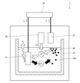
- FIG. 1 is a diagram schematically showing the principle of a method for producing carbon particles using carbon dioxide as a raw material
- FIG. It is a photograph showing an example of mud carbon.
- 4 is a photograph showing an example of massive carbon
- FIG. 2 is a diagram schematically showing a crystallite spacing d (200) and crystallite sizes Lc (002) and La (110).
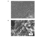
- FIG. 4 is a diagram showing the particle size distribution (A) of carbon particles in muddy carbon of Example 2A and the particle size distribution (B) of carbon particles in massive carbon of Example 2B. SEM photographs of the carbon particles of Example 2A, (A) 5 kV ⁇ 1000 and (B) 5 kV ⁇ 10000.
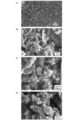
- FIG. 7(B) SEM photographs of carbon particles of Example 2B, (A) 5 kV ⁇ 1000, (B) 5 kV ⁇ 10000, (C) and (D) being partial enlarged views of FIG. 7(B).
- FIG. 11 shows X-ray diffraction profiles of (A) before heat treatment and (B) after heat treatment in Example 7;
- FIG. 3 is a diagram showing the interplanar spacing d(002) between carbon particles and graphite particles in Examples 1A to 7A.
- FIG. 2 shows (A) Lc(002) and (B) La(110) of carbon particles and graphite particles of Examples 1A to 7A.
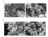
- FIG. 10 is an SEM image of (A) carbon particles (before heat treatment) and (B) graphite particles (after heat treatment) of Example 4A.
- A SEM images of carbon particles (before heat treatment) and graphite particles (after heat treatment) of Example 6A and (B) Example 7A. It is an SEM image used for visually measuring the primary particle size of Example 4A.
- FIG. 4 is a diagram showing changes in specific surface area depending on heat treatment temperature in Examples 4A and 4B.
- FIG. 4 shows cyclic voltammograms measured in molten salt containing CO 3 ;
- FIG. 10 is a diagram showing the particle size distribution of carbon particles of Example 8; SEM photograph of the carbon particles of Example 8, the acquisition conditions being 5 kV ⁇ 10000.
- FIG. 11 shows X-ray diffraction profiles before (A) heat treatment and after (B) heat treatment in Example 8; SEM photograph of the graphite particles of Example 8, the acquisition conditions being 5 kV ⁇ 10000.
- FIG. 4 is a diagram showing the relationship between the utilization rate and the discharge rate (discharge current (C rate)) of Example B1 and Comparative Example B1.
- FIG. 10 is a diagram showing the particle size distribution of carbon particles of Example 8; SEM photograph of the carbon particles of Example 8, the acquisition conditions being 5 kV ⁇ 10000.
- FIG. 11 shows X-ray diffraction profiles before (A) heat treatment and after (B) heat treatment in Example 8; SEM photograph of the graphite particles of Example 8, the acquisition conditions
- FIG. 10 is a diagram showing the relationship between the utilization rate and the discharge rate (discharge current (C rate)) of Example B2 and Comparative Example B2.
- FIG. 4 is a diagram showing the relationship between the charging rate and the charging rate (charging current (C rate)) in Example B1 and Comparative Example B1.
- FIG. 10 is a diagram showing the relationship between the utilization rate and the discharge rate (discharge current (C rate)) of Example B4 and Comparative Example B4.
- FIG. 10 is a diagram showing the relationship between the utilization rate and the discharge rate (discharge current (C rate)) of Example B6 and Comparative Example B6.
- FIG. 10 is a diagram showing the relationship between the charging rate and the charging rate (charging current (C rate)) of Example B6 and Comparative Example B6.
- the "primary particle size” means the arithmetic average particle size by visual measurement with an electron microscope (SEM), and the “secondary particle size (d50)" is based on number.
- the integrated value of the particle size distribution means a value of 50%
- the "specific surface area” means the BET specific surface area obtained from the nitrogen adsorption amount at 77K.
- the graphite particles according to the present invention have a plane spacing d002 based on the diffraction peak corresponding to the lattice plane (002) measured by a powder X-ray diffraction method of 0.3355 nm or more and 0.3370 nm or less, and a primary particle diameter of It has a particle size of 50 nm or more and 500 nm or less, a secondary particle diameter (d50) of 0.15 ⁇ m or more and 1.6 ⁇ m or less, and a specific surface area (BET) of 10 m 2 /g or more and 400 m 2 /g or less.
- the graphite particles according to the present invention are produced by producing carbon particles using carbon dioxide as a raw material and heat-treating the obtained carbon particles.
- a method for producing carbon particles using carbon dioxide as a raw material will be described below.
- a container 10 containing an electrolytic bath 100, an anode 21, a cathode 22, and an anode 21 and a cathode 22 are connected.
- a power supply unit 23 and a carbon dioxide supply unit 30 are provided.
- the electrolytic bath 100 contains a molten salt and a metal oxide as a source of oxide ions (O 2 ⁇ ).
- the metal oxide supplies oxide ions (O 2 ⁇ ) in the electrolytic bath 100 . Note that the oxide ions may be supplied into the electrolytic bath 100 by other methods.
- a portion of the O 2 ⁇ produced at the cathode is oxidized to produce oxygen gas according to equation (3) when the anode is the oxygen-evolving anode.
- the overall reaction is the electrolysis of carbon dioxide to obtain carbon fine particles and oxygen as shown in the following formula. It will be.
- Alkali metal halides, alkaline earth metal halides, alkali metal carbonates, and alkaline earth metal carbonates can be used as the molten salt.
- Alkali metal halides include compounds such as LiF, NaF, KF, RbF, CsF, LiCl, NaCl, KCl, RbCl, CsCl, LiBr, NaBr, KBr, RbBr, CsBr, LiI, NaI, KI, RbI, and CsI. can be used.
- Alkaline earth metal halides include MgF2 , CaF2 , SrF2, BaF2 , MgCl2, CaCl2 , SrCl2, BaCl2 , MgBr2 , CaBr2 , SrBr2 , BaBr2 , MgI2 , CaI2 , SrI 2 , BaI 2 and the like can be used.
- alkali metal carbonates carbonates such as Li 2 CO 3 , Na 2 CO 3 and K 2 CO 3 can be used.
- Carbonates such as MgCO 3 , CaCO 3 and BaCO 3 can be used as alkaline earth metal carbonates.
- ⁇ Oxide ion (O 2 ⁇ ) source An oxide ion (O 2 ⁇ ) source is previously supplied in the electrolytic bath.
- Alkali metal oxides and alkaline earth metal oxides can be used as the oxide ion (O 2 ⁇ ) source.
- oxides such as Li 2 O, Na 2 O and K 2 O can be used.
- oxides such as MgO, CaO and BaO can be used.
- the treatment temperature bath temperature of the electrolytic bath.
- the thermal decomposition of the carbonate itself becomes noticeable, and the materials of the electrolytic cell that can be used are limited, making it difficult to handle. preferable.
- the cathode is not immersed in the electrolytic bath, but is arranged outside the electrolytic bath and near the surface of the electrolytic bath. That is, instead of reducing carbonate ions on the cathode surface immersed in the electrolytic bath, carbonate ions can be reduced by discharged electrons near the surface of the electrolytic bath. By doing so, carbon particles are formed from the atomic level, so extremely fine carbon particles can be formed.
- cathode As materials for the cathode, various metals such as iron, nickel, molybdenum, tantalum, and tungsten, alloys thereof, carbon materials such as glassy carbon and conductive diamond, conductive ceramics, semiconducting ceramics, and the like can be used. A thin film formed of these materials on a different material can also be used as the cathode.
- an electrode material that can oxidize O 2 ⁇ produced by the reduction reaction of carbonate ions (CO 3 2 ⁇ ) shown in formula (2) is used.
- carbonate ions CO 3 2 ⁇
- predominantly carbon or insoluble anodes are used.
- a conductive ceramic electrode made of nickel-cobalt oxide represented by .5) or a conductive diamond electrode can be used.
- the carbon particles formed in the electrolytic bath described above exist in the following two states in the molten salt.
- One is a state in which carbon particles are dispersed in a molten salt bath to form a muddy state (hereinafter referred to as "muddy carbon") (Fig. 2).
- the other is a state in which aggregates of carbon particles grow to form clumps of about several centimeters, and molten salt is involved in the clumps (hereafter referred to as "clumped carbon”) (Fig. 3).
- the electrolytic bath containing muddy carbon and lumpy carbon are separated and transferred to the outside of the electrolytic cell, where they are solidified at room temperature.
- the solidified salt is individually dissolved in water or warm water of 50° C. or less, and the carbon particles are suspended in the aqueous solution while applying ultrasonic waves.
- the resulting suspension is filtered through a membrane filter, and the carbon particles deposited on the filter are dried to obtain carbon powder.
- the shape of the carbon particles finally obtained in the recovery process described above may be spherical, sheet-like, ribbon-like, or cube-like. It is considered that the carbon particles having various shapes can be obtained because the reduction of carbonate ions is used for the production of the carbon particles.
- the carbon particles may be produced by other methods, and may be composed of single-shaped particles.
- the interplanar spacing d(002) of the carbon particles is preferably 0.3360 nm or more and 0.3373 nm or less.
- the secondary particle diameter (d50) of the carbon particles is preferably 150 nm or more and 200 nm or less.
- the BET specific surface area of the carbon particles is preferably 200 m 2 /g or more and 600 m 2 /g or less. In one embodiment, such carbon particles can be heat treated as described below to obtain graphite powder suitable for use in electrode materials.
- the carbon particles obtained as described above are heat-treated and graphitized.
- the heat treatment temperature is preferably 2800° C. or higher. Since no carbon precursor binder needs to be added to the carbon particles, it is not affected by the binder composition.
- the interplanar spacing d002 based on the diffraction peak corresponding to the lattice plane (002) measured by the powder X-ray diffraction method of the graphite particles according to the present invention is 0.3355 nm or more and 0.3370 nm or less.
- the primary particle size of the graphite particles is 50 nm or more and 500 nm or less, and the value (average particle size) at which the integrated value of the particle size distribution based on the number of graphite particles is 50% is defined as the secondary particle size (d50).
- the diameter (d50) is 0.15 ⁇ m or more and 1.6 ⁇ m or less.
- the specific surface area (BET) of the graphite particles obtained from the nitrogen adsorption amount at 77 K is 10 m 2 /g or more and 400 m 2 /g or less, preferably 50 m 2 / g or more and 70 m 2 /g or less.
- Graphite powder which is an aggregate of graphite particles, contains graphite particles of various shapes. Typical shapes of carbon particles contained in the carbon powder before heat treatment are sheet-like, ribbon-like, and cube-like. Graphite particles obtained by heat-treating carbon particles containing carbon particles of different shapes also include graphite particles of different shapes. The graphite particles preferably include sheet-like, ribbon-like and cube-like carbon particles. The graphite particles may consist of graphite particles of a single shape.
- Graphite powder which is an aggregate of graphite particles according to the present invention, functions as an electrode material for non-aqueous secondary batteries.
- a non-aqueous secondary battery is a device or element that has at least a positive electrode, a negative electrode, and a non-aqueous electrolyte, extracts energy chemically stored by a carrier in the form of electric power, and can be recharged.
- a carrier is an ion responsible for electric conduction, and examples thereof include lithium ion, sodium ion, potassium ion, magnesium ion, calcium ion, aluminum ion, fluoride ion, chloride ion, and iodide ion.
- non-aqueous secondary batteries include lithium ion batteries, sodium ion batteries, potassium ion batteries, magnesium ion batteries, calcium ion batteries, aluminum ion batteries, fluoride ion batteries, chloride ion batteries, iodide ion batteries and later described. It is a battery system that is generically called a dual-ion battery or the like.
- an electrode material refers to an active material that can reversibly occlude and release anions or cations. That is, the present electrode material functions as a positive electrode when absorbing and releasing anions, and as a negative electrode when absorbing and releasing cations.
- Anions of the present disclosure include, for example, PF 6 ⁇ , BF 4 ⁇ , ClO 4 ⁇ , TiF 4 ⁇ , VF 5 ⁇ , AsF 6 ⁇ , SbF 6 ⁇ , CF 3 SO 2 ⁇ , (CF 3 SO 2 ) 2 N ⁇ , B(C 2 O 4 ) 2 ⁇ , B 10 Cl 10 ⁇ , B 12 Cl 12 ⁇ , CF 3 COO ⁇ , S 2 O 4 2 ⁇ , NO 3 ⁇ , SO 4 2 ⁇ , PF 3 (C 2 F 5 ) 3 ⁇ , (FSO 2 ) 2 N ⁇ , CF 3 SO 3 ⁇ , FeCl 4 ⁇ and other negatively charged atomic groups.
- These anions are preferably atomic groups containing halogen such as F, Cl, Br, and I. Among them, atomic groups containing F are preferable from the viewpoint of high battery voltage.
- the electrode of the present invention is used as a positive electrode, and in a battery system in which the positive electrode absorbs an anion to charge and releases an anion to discharge, the anion is an atomic group containing F. , regardless of the counter electrode, is called a fluoride ion battery. Similarly, an atomic group containing Cl is called a chloride ion battery, an atomic group containing Br is called a bromide ion battery, and an atomic group containing I is called an iodide ion battery.
- the anion used in these batteries preferably has an ionic radius of 0.23 nm or more and 0.29 nm or less. This is because if the thickness is less than 0.23 nm, the anions occluded by the carbon material are less likely to be released, and if the thickness exceeds 0.29 nm, the carbon material is less likely to occlude anions.
- the anion preferably has a Van der Waals volume in the range of 0.04 nm 3 or more and 0.10 nm 3 or less. This is because if it is less than 0.04 nm 3 , it is difficult for the carbon material to release the anions occluded, and if it exceeds 0.10 nm 3 , it is difficult for the carbon material to occlude anions.
- PF 6 - , BF 4 - , AsF 6 - , SbF 6 - or CF 3 SO 3 - are preferred, and PF 6 - is preferred from the viewpoint of cycle life and discharge capacity.
- Cations in the present disclosure refer to positively charged ions such as, for example, Li + , Na + , K + , Mg 2+ , Ca 2+ , Al 3+ .
- Alkali metal ions such as Na + or K + are preferable because the graphite of the present invention exhibits superior input/output characteristics and high electric capacity compared to conventional graphite.
- General graphite can occlude and release Li + and K + , but cannot occlude and release large amounts of ions such as Na + , Mg 2+ , Ca 2+ and Al 3+ .
- the graphite of the present invention can occlude and release ions such as Li + , Na + , K + , Mg 2+ , Ca 2+ , and Al 3+ in larger amounts than conventional graphite.
- the electrode of the present invention absorbs cations to charge and release cations to discharge, when the cation is Li + , They are called lithium-ion batteries.
- lithium-ion batteries sodium ion batteries if Na +
- a battery that can be charged and discharged by using the electrodes of the present invention as a positive electrode and a negative electrode, with the positive electrode absorbing and releasing anions and the negative electrode absorbing and releasing cations, is called a dual-ion battery.
- This battery system is characterized in that the salt concentration in the non-aqueous electrolyte decreases upon charging.
- a secondary battery that uses both cations and anions in the electrolytic solution as carriers involved in redox reactions (Toshihiro Nakabo et al.: Nissin Denki Gijutsu, Vol. 57 (2) 28-31 (2012) ).
- a carbon-based material is known as an active material capable of reversibly absorbing and desorbing the cation Li + and the anion PF 6 ⁇ (Japanese Patent Application Laid-Open No. 2013-054987).
- an electrode for a non-aqueous secondary battery such as a positive electrode, a negative electrode, or a bipolar electrode, which will be described later.
- the adhesion forming method is not particularly limited, but includes, for example, a pressure bonding method, a slurry method (paste method), an electrophoresis method, a dipping method, a spin coating method, an aerosol deposition method, and the like.
- the electrode for the non-aqueous secondary battery according to the present invention is not essential because the present carbon material itself has conductivity, but in order to further improve the conductivity, it may contain a conductive aid as necessary. good too.
- a conductive aid there are no particular restrictions on the type of conductive aid, and for example, carbon-based conductive aids such as acetylene black, furnace black, vapor-grown carbon fiber, carbon nanotube, graphene, and carbon nanohorn can be used.
- the electrode for non-aqueous secondary batteries according to the present invention may contain a binder.
- a binder There are no particular restrictions on the type of binder, and commonly used binders such as polyvinylidene fluoride (PVDF), carboxymethyl cellulose (CMC), styrene-braziene rubber (SBR), acrylic resin, and polyimide can be used. can.
- PVDF polyvinylidene fluoride
- CMC carboxymethyl cellulose
- SBR styrene-braziene rubber
- acrylic resin acrylic resin
- polyimide polyimide
- the electrode for non-aqueous secondary batteries according to the present invention may contain an active material capable of reversibly absorbing and releasing anions or cations.
- an active material capable of reversibly absorbing and releasing anions or cations.
- Cu, Ni, stainless steel, carbon, etc. can be used as the negative electrode of the lithium ion battery.
- Al, Cr, Ti, Co, W, WC, stainless steel, carbon, etc. should be used when used as the positive electrode for any of fluoride ion batteries, chloride ion batteries, bromide ion batteries, and iodide ion batteries. can be done.
- each current collector can be used for the above-mentioned positive electrode and negative electrode.
- the shape of the current collector is not particularly limited, but examples thereof include foil-like, plate-like, mesh, woven fabric, non-woven fabric, foam, expanded, and punched metal.
- bipolar electrode when used as a bipolar electrode, it preferably has a shape without through holes (for example, foil-like or plate-like).
- Al can be used commonly for the current collectors of the positive electrode and the negative electrode.
- Al is a lightweight and highly conductive metal, and is inexpensive.
- a bipolar electrode is obtained by using one sheet of Al foil as a current collector and providing a positive electrode layer and a negative electrode layer on the front and back of this current collector, respectively.
- the electrode material for non-aqueous secondary batteries of the present invention, a binder, and optionally a conductive aid are mixed to form a slurry. is applied to the current collector, temporarily dried, and then subjected to heat treatment to obtain an electrode.
- Temporary drying is not particularly limited as long as the solvent in the slurry can be volatilized and removed, but for example, a method of performing heat treatment in an atmosphere at a temperature of 50°C or higher and 300°C or lower can be mentioned.
- the above heat treatment can be performed by holding at 50° C. or higher and 300° C. or lower for 1 hour or longer and 50 hours or shorter under reduced pressure.
- the electrode for a non-aqueous secondary battery of the present invention When the electrode for a non-aqueous secondary battery of the present invention is used as a positive electrode, the electrode is charged and discharged at a lower limit potential of 2.0 V (relative to lithium potential) or higher and an upper limit potential of 5.5 V (relative to lithium potential) or lower. is preferred. Even if the discharge is performed at less than 2 V, the capacity is not obtained and not only is it useless, but there is a high possibility that the negative electrode will be oxidized. Charging above 5.5 V tends to decompose the electrolyte.
- the lower limit potential is more preferably 2.0V, more preferably 2.5V. Moreover, it is more preferable to set the upper limit potential to 5.0V.
- the electrode for a non-aqueous secondary battery of the present invention When the electrode for a non-aqueous secondary battery of the present invention is used as a negative electrode, charge and discharge is performed at a lower limit potential of 0.0 V (relative to lithium potential) or higher and an upper limit potential of 2.0 V (relative to lithium potential) or lower. is preferred. At potentials below 0 V, the negative electrode is overcharged, increasing the likelihood that cations become metallic and deposit on the electrode.
- the lower limit potential is more preferably 0.001V, more preferably 0.01V. Moreover, it is more preferable to set the upper limit potential to 1.5V.
- the electrode (positive electrode or negative electrode) obtained in this way is joined to the counter electrode via a separator, immersed in a non-aqueous electrolyte (electrolytic solution) and sealed to form a secondary battery.
- a non-aqueous electrolyte electrolytic solution
- bipolar electrodes the bipolar electrodes are joined via a separator, and sealed while immersed in a non-aqueous electrolyte (electrolytic solution) to form a secondary battery.
- the electrolyte salt thereof is preferably a salt composed of the above-described anions and cations.
- examples of the solvent for the electrolyte include propylene carbonate, ethylene carbonate, dimethyl carbonate, diethyl carbonate, ⁇ -butyrolactone, and the like, and one or more of them can be used.
- propylene carbonate alone and a mixture of ethylene carbonate and diethyl carbonate are preferable.
- the mixing ratio of the mixture of ethylene carbonate and diethyl carbonate can be arbitrarily adjusted within the range of 10% or more and 90% or less.
- non-aqueous secondary battery having the structure described above, it can function as a secondary battery with high potential and excellent input/output characteristics.
- the structure of the non-aqueous secondary battery is not particularly limited when the electrode of the present invention is used as a positive electrode or negative electrode, and can be applied to existing battery forms and structures such as stacked batteries and wound batteries.
- a battery using a bipolar electrode has a structure in which a plurality of bipolar electrodes, each having a positive electrode layer on one side of a current collector and a negative electrode layer on the other side, are laminated via a separator containing an electrolytic solution. Since the single cells are arranged in series in the stacking direction in the battery, the current flows in the thickness direction of the battery. Due to the advantages of a short battery path and low current loss, a battery with high output characteristics and high energy density can be obtained.
- an insulating material polyolefin, fluorine-based resin, etc.
- a bipolar electrode is an electrode in which a positive electrode layer and a negative electrode layer are provided on both sides of a single current collector. different.
- Japanese Unexamined Patent Application Publication No. 2012-129095, Japanese Unexamined Patent Application Publication No. 2021-150106, etc. Therefore, it has been forced to provide active material layers with different properties on the front and back sides of the current collector.
- the electrode material (active material) of the present invention can operate as both a positive electrode active material and a negative electrode active material, layers of the same material can be provided on the front and back of the current collector. As a result, the number of manufacturing steps of the battery and the number of parts required for the configuration can be reduced.
- the electrode material (active material) of the present invention has the same electric capacity as a negative electrode and a positive electrode. Become. Therefore, even if the electrodes have the same basis weight (coating amount), a difference in capacity between the positive electrode and the negative electrode is unlikely to occur, and charging and discharging can be performed efficiently.
- Electrodes with different basis weights on the front and back have the disadvantage of causing a difference in stress between the front and back during the drying process and pressing process during electrode production, which tends to cause bending of the electrode and peeling of the active material layer. In other words, if the basis weights of the front and back sides are the same, such a problem is less likely to occur.
- the non-aqueous secondary battery equipped with the electrode of the present invention does not contain rare metals in the active material and exhibits high input/output characteristics, so it can be used as a power source for various electrical devices (including vehicles that use electricity). can be done.
- Examples of electrical equipment include air conditioners, washing machines, televisions, refrigerators, freezers, cooling equipment, laptop computers, computer keyboards, computer displays, desktop computers, laptop computers, CRT monitors, computer racks, printers, and all-in-one computers.
- mouse hard disk, computer peripherals, iron, clothes dryer, window fan, transceiver, blower, ventilation fan, TV, music recorder, music player, oven, microwave, toilet seat with washing function, warm air heater, car component, car navigation system, pocket Lights, humidifiers, portable karaoke machines, ventilation fans, dryers, batteries, air purifiers, mobile phones, emergency lights, game consoles, blood pressure gauges, coffee mills, coffee makers, kotatsu, copiers, disc changers, radios, shavers , juicer, shredder, water purifier, lighting equipment, dehumidifier, dish dryer, rice cooker, stereo, stove, speaker, trouser press, flying car, vacuum cleaner, body fat scale, weight scale, health meter, movie player, Electric carpet, electric kettle, rice cooker
- a molten salt As a molten salt, 900 to 3100 g of a eutectic salt of LiCl and KCl (eutectic composition: 58.5:41.5 mol%) was melted under an argon atmosphere at atmospheric pressure and held at 450°C. K 2 CO 3 was added to the molten salt as a carbonate ion source in an amount to give a salt concentration of 2 mol %, and the electrolytic bath was stirred by blowing argon gas to suspend and disperse it in the electrolytic bath. A carbon plate was placed as an anode in the electrolytic bath. Outside the electrolytic bath, a tungsten rod was arranged as a cathode, which is a discharge electrode, near the surface of the electrolytic bath. Discharge electrolysis was performed on the above electrolytic bath at an electrolytic current of 2 A to 4 A and an amount of electricity of 107,208 to 450,000 C (coulomb).
- Examples 1 to 7 differ in the weight of molten salt, electrolysis current, and quantity of electricity.
- the weight of the molten salt, the electrolytic current, and the amount of energization are respectively 900 g, 3 A, and 107208 C in Example 1, 1350 g, 2 A, and 200,000 C in Examples 2 to 5, and 3,100 g and 2 A in Examples 6 to 7. , 450,000C.
- muddy carbon and massive carbon were formed in the electrolytic bath in all examples. Mud-like carbon and block-like carbon were each moved to the outside of the electrolytic cell and turned into a solidified salt at room temperature.
- the solidified salt containing muddy carbon and the solidified salt containing lumpy carbon were individually dissolved in hot water or water at 50° C. or lower, and the carbon particles were suspended in the aqueous solution while applying ultrasonic waves.
- the obtained aqueous solution was filtered with a membrane filter, and the carbon particles deposited on the filter were dried.
- Examples 1 to 7 muddy carbon will be referred to as Examples 1A to 7A
- lumpy carbon will be referred to as Examples 1B to 7B.
- the interplanar spacing d (002) (nm) of the (002) plane of the carbon particles and the crystallite size (Lc (002) (nm), La (110) nm) are measured by XRD (X-ray diffraction method) Gakushin method. bottom.
- the average secondary particle size (d50) (nm) was measured using a particle size distribution measuring device: Nanotrac UPA, model UPA-EX manufactured by Microtrac Bell Co., Ltd.
- the specific surface area was measured by the BET method obtained from the amount of nitrogen adsorption at 77K.
- the layer spacing (d(002)) of the carbon particles of Examples 1A to 7A (muddy carbon) is 0.3360 nm or more and 0.3373 nm or less, and particles having crystallinity equivalent to that of graphite. was included.
- both the muddy carbon (Example 2A) and the lumpy carbon (Example 2B) had a secondary particle size (d50) of 150 nm or more and 200 nm or less of the carbon particles obtained after washing and drying. .
- the BET specific surface area of the carbon particles was 200 m 2 /g or more and 500 m 2 /g or less.
- ⁇ Shape of carbon particles> The carbon particles of Examples 2A and 2B were observed with an SEM (manufactured by JEOL Ltd., JSM-6010PLUS/LA). As shown in FIGS. 6 and 7, the carbon particles were not only spherical, but also included particles with sheet-like, ribbon-like, and cube-like structures, including particles of various shapes.
- the area surrounded by line A is sheet-shaped carbon particles
- the area surrounded by line B is ribbon-like carbon particles
- the area surrounded by line C is cube-shaped. of carbon particles are observed.
- both muddy carbon (Example 2A) and lumpy carbon (Example 2B) contained not only spherical carbon particles but also sheet-like particles, ribbon-like particles, and cube-like particles. was found to contain particles of various shapes. Thus, carbon powder containing carbon particles of various shapes could be produced using carbonate ions as a raw material.
- the interplanar spacing d(002) based on the diffraction peak corresponding to d(002) of the graphite particles of Examples 1 to 7 was 0.3355 nm or more and 0.3365 nm or less.
- the graphite peak is a low-crystalline peak that is a turbostratic structure component (T component) at a diffraction angle (2 ⁇ ) of 26°, and a highly crystalline peak that is a graphitized component (G component) at a diffraction angle (2 ⁇ ) of 26.5°.
- T component turbostratic structure component
- G component graphitized component
- the carbon particles before the heat treatment which is the raw material of the graphite particles, do not have a peak near 26.5° and are not graphitic, but after the heat treatment, the diffraction angle (2 ⁇ ) A peak at a diffraction angle (2 ⁇ ) of 26.5° was higher than that at 26°, revealing the existence of a graphite structure in the particles.
- the degree of graphitization P1 was obtained from the following formula.
- the interplanar spacing d (002) between the carbon particles before heat treatment and the graphite particles after heat treatment was investigated.
- the theoretical value of d(002) for graphite is 0.3354 nm.
- the d(002) after graphitization of the carbon particles of Examples 1 to 7 was in the range of 0.3355 nm to 0.3368 nm, which was equivalent to that of artificial graphite and natural graphite. As shown in FIG. 10, it can be seen that the heat treatment reduces the variation in d(002) between the examples.
- artificial graphite manufactured by SEC Carbon Co., Ltd. has Lc (002) of 117 nm and La (110) of 284.6 nm.
- the crystallite sizes of the graphite particles of Examples 1 to 7 for both Lc(002) and La(110) are 1/3 or less of that of general artificial graphite.
- Table 5 shows the average and standard deviation of La and Lc before and after the heat treatment of Examples 1A to 7A (muddy carbon).
- the secondary particle size of graphite particles is 0.15 ⁇ m or more and 1.6 ⁇ m or less.
- the particle size of the graphite particles after the heat treatment at 2800° C. is significantly larger than that of the carbon particles before the heat treatment.
- the particle diameter of the carbon material as a raw material is 180 nm (d50)
- the particle diameter of graphite is 1600 nm (d50).
- SEM observation confirmed fusion of particles due to the heat treatment.
- Example 6 and 7 the particle size after graphitization was approximately the same as the particle size of the raw material carbon particles. As shown in FIG. 13, as a result of SEM observation of Examples 6 and 7, it was confirmed that fusion of carbon particles due to heat treatment did not occur.
- the primary particle size of the graphite particles of Examples 1 to 7 was 50 nm or more and 500 nm or less, as determined by visual measurement using an SEM (electron microscope).
- the graphite particles of Examples 1 to 7 had a specific surface area (BET) of 50 m 2 /g or more and 60 m 2 /g or less as determined from the nitrogen adsorption amount at 77K.
- BET specific surface area
- the specific surface area of the raw material carbon particles was 300 m 2 /g or more and 500 m 2 /g or less. After the heat treatment, the higher the heat treatment temperature, the more the specific surface area tended to decrease. The reason for this is thought to be that the heat treatment caused the carbon particles to fuse together, resulting in an increase in particle size.
- the graphite powder was observed with an SEM (JSM-6010PLUS/LA manufactured by JEOL Ltd.).
- the shape of the graphite particles was not limited to spherical, but there were also particles having sheet-like, cube-like, and ribbon-like structures, and graphite particles of various shapes were found.
- the graphite particles included not only spherical particles but also sheet-like particles, ribbon-like particles, and cube-like particles, and included particles of various shapes.
- the reason why the graphite particles with such various shapes are formed is that the particle shapes are already diversified at the stage of the carbon particles as the raw material.
- carbon particles with various morphologies can be obtained by cathodic discharge electrolysis of carbonate ions in the molten salt, and it is thought that the graphite particles obtained by heat treatment also have various morphologies. .
- the treatment temperature for graphitization is preferably 2800° C. or higher.
- a eutectic salt of LiCl and KCl (eutectic composition: 58.5:41.5 mol%) was melted under an argon atmosphere at atmospheric pressure and held at 450°C.
- Li 2 O was added to the molten salt as an oxide ion source in an amount to give a concentration of 1 mol %, and the electrolytic bath was stirred by blowing argon gas to suspend and disperse it in the electrolytic bath. After that, argon gas containing 10 vol % of carbon dioxide was blown into the electrolytic bath at a flow rate of 100 mL/min for 24 hours.
- an Ag(I)/Ag electrode consisting of a Ni wire as the cathode, a glassy carbon rod as the anode, and a LiCl-KCl eutectic salt containing 1 mol% AgCl as a reference electrode and an Ag wire was used as the reference electrode. was used to perform cyclic voltammetry at a scan rate of 10 mV/s. For comparison, a similar measurement was performed with a molten salt containing K 2 CO 3 equivalent to 2.0 mol % at a scanning rate of 100 mV/s.
- muddy carbon was formed in the electrolytic bath after electrolysis.
- the muddy carbon was moved to the outside of the electrolytic cell and turned into a solidified salt at room temperature.
- a solidified salt containing muddy carbon was dissolved in warm water or water at a temperature of 50° C. or less, and carbon particles were suspended in the aqueous solution while applying ultrasonic waves.
- the obtained aqueous solution was filtered with a membrane filter, and the carbon particles deposited on the filter were dried.
- Example 8 The interplanar spacing d (002) (nm) of the (002) plane of the carbon particles recovered in Example 8, the crystallite size (Lc (002) (nm), La (110) nm), the average secondary particle size ( d50) (nm) and specific surface area were measured.
- the results of Example 8 are shown in Table 7. These measurement methods are the same as in Examples 1-7.
- the layer spacing (d(002)) of the carbon particles of Example 8 was 0.3362 nm, and particles having a crystallinity equivalent to that of graphite were included as in Examples 1 to 7. rice field.
- the secondary particle diameter (d50) of the carbon particles obtained after washing and drying was 193.2 nm, which was equivalent to Examples 1-7.
- the BET specific surface area of the carbon particles was 523 m 2 /g, which was equivalent to Examples 1-7.
- Example 8 The carbon particles of Example 8 were observed by SEM. As shown in FIG. 18, as in Examples 1 to 7, carbon particles are not only spherical, but also have sheet-, ribbon-, and cube-like structures, including particles of various shapes. board. In FIG. 18, the area surrounded by line A is sheet-like carbon particles, the area surrounded by line B is ribbon-like carbon particles, the area surrounded by line C is cube-like carbon particles, and the area surrounded by line D is Spherical carbon particles are observed in some parts.
- the interplanar spacing d(002) based on the diffraction peak corresponding to d(002) of the graphite particles of Example 8 was 0.3369 nm.
- Table 10 shows the results of obtaining the degree of graphitization P1, which indicates the progress of graphitization. The closer P1 is to 1, the more graphitization has progressed.
- the interplanar spacing d(002) based on the diffraction peak corresponding to d(002) of the graphite particles of Example 8 was 0.3369 nm, a value equivalent to that of artificial graphite and natural graphite.
- artificial graphite manufactured by SEC Carbon Co., Ltd. has Lc (002) of 117 nm and La (110) of 284.6 nm.
- the crystallite size of the graphite particles of Example 8, both Lc(002) and La(110), is 1/4 or less that of general artificial graphite.
- the primary particle diameter of the graphite particles of Example 8 was 50 nm or more and 500 nm or less, as in Examples 1 to 7, by visual measurement using an SEM (electron microscope).
- the graphite particles of Example 8 had a specific surface area (BET) of 68.6 m 2 /g determined from the amount of nitrogen adsorption at 77K.
- the shape of the graphite particles is not only spherical, but also particles having a sheet-like, cube-like, or ribbon-like structure.
- Graphite particles of various shapes were obtained.
- the area surrounded by line A is sheet-like graphite particles
- the area surrounded by line B is ribbon-like graphite particles
- the area surrounded by line C is cube-like graphite particles
- the area surrounded by line D is Spherical graphite particles are observed in some parts.
- graphite particles obtained by heat-treating carbon particles produced by electrolysis using carbon dioxide as a raw material for carbonate ions are not only spherical particles, but also sheet-like particles, ribbon-like particles, and It was found that cubic particles were mixed and particles of various shapes were included.
- Example B1 Graphite powder (Example 2A, particle size 1200 nm (d50)), which is an aggregate of graphite particles of the present invention, was used as a positive electrode active material, and 83% by mass of the positive electrode active material, 2% by mass of acetylene black, and 15% by mass of polyvinylidene fluoride. % to prepare a slurry-like mixture, apply it on an aluminum foil current collector with a thickness of 12 ⁇ m, heat-treat (150 ° C.
- Example B1 a metallic lithium foil having a thickness of 500 ⁇ m was used as the counter electrode. It was prepared by providing a mixture of 1 mol/L lithium hexafluorophosphate (LiPF 6 ), ethylene carbonate (EC) and diethyl carbonate (DEC).
- LiPF 6 lithium hexafluorophosphate
- EC ethylene carbonate
- DEC diethyl carbonate
- Example B2 In the battery of Example B2, a metallic sodium foil with a thickness of 500 ⁇ m was used as the counter electrode, and a mixture of sodium hexafluorophosphate (NaPF 6 ) with a salt concentration of 1 mol/L, EC and DEC was used as the electrolyte. Otherwise, it is the same as Example B1.
- Example B3 In the battery of Example B3, a metal potassium foil with a thickness of 500 ⁇ m was used as the counter electrode, and potassium bis(trifluoromethane)sulfonamide (KTFSA) and 1-methyl-1- Same as Example B1 except that a mixture of propylpyrrolidinium bis(trifluoromethanesulfonyl)amides (Pyr13TFSA) was used.
- KTFSA potassium bis(trifluoromethane)sulfonamide
- Pyr13TFSA propylpyrrolidinium bis(trifluoromethanesulfonyl)amides
- Comparative Example B1 In the battery of Comparative Example B1, natural graphite (manufactured by Aldrich; 496596 graphite powder, ⁇ 325 mesh; hereinafter referred to as “natural graphite”) having a maximum particle size of 44 ⁇ m (FISHER diameter of 3.5 ⁇ m) was used as the positive electrode active material. Otherwise, it is the same as the battery of Example B1.
- natural graphite manufactured by Aldrich; 496596 graphite powder, ⁇ 325 mesh; hereinafter referred to as “natural graphite” having a maximum particle size of 44 ⁇ m (FISHER diameter of 3.5 ⁇ m) was used as the positive electrode active material. Otherwise, it is the same as the battery of Example B1.
- Comparative Example B2 The battery of Comparative Example B2 is the same as the battery of Example B2, except that natural graphite is used as the positive electrode active material.
- Comparative Example B3 The battery of Comparative Example B3 is the same as the battery of Example B3, except that natural graphite is used as the positive electrode active material.
- Example B4 ⁇ Production of battery using negative electrode for lithium ion battery>
- the graphite powder of Example 2A of the present invention was used as a negative electrode active material, and 83% by mass of the negative electrode active material, 2% by mass of acetylene black, and 15% by mass of polyvinylidene fluoride were mixed to form a slurry.
- a mixture was prepared and coated on a copper foil current collector having a thickness of 10 ⁇ m, and the other steps were the same as those of the battery of Example B1.
- Comparative Example B4 The battery of Comparative Example B4 is the same as the battery of Example B4, except that natural graphite is used as the negative electrode active material.
- Example B5 ⁇ Production of battery using negative electrode for sodium ion battery>
- the battery of Example B5 used an aluminum foil with a thickness of 12 ⁇ m as the current collector of the test electrode, a metallic sodium foil with a thickness of 500 ⁇ m as the counter electrode, and NaPF 6 , EC and DEC with a salt concentration of 1 mol / L as the electrolyte solution. It is the same as Example B4 except that a mixture of
- Comparative Example B5 The battery of Comparative Example B5 is the same as the battery of Example B5, except that natural graphite is used as the negative electrode active material.
- Example B6 ⁇ Production of battery using negative electrode for potassium ion battery>
- a metal potassium foil with a thickness of 500 ⁇ m was used as the counter electrode, and potassium bis(fluorosulfonyl)amide (KFSA) and 1-methyl-1-propylpyrrolidone having a salt concentration of 1 mol/L were used as the electrolyte.
- KFSA potassium bis(fluorosulfonyl)amide
- 1-methyl-1-propylpyrrolidone having a salt concentration of 1 mol/L
- Comparative Example B6 The battery of Comparative Example B6 is the same as the battery of Example B6 except that natural graphite is used as the negative electrode active material.
- Table 12 shows the reversible capacities of the active materials of Examples B1 to B6 and Comparative Examples B1 to B6.
- Examples B1 to B4 When used as a positive electrode for a fluoride ion battery or a negative electrode for a lithium ion battery, the reversible capacities of Examples (Examples B1 to B4) were equal to or lower than those of Comparative Examples (Comparative Examples B1 to B4). However, when used as a negative electrode for a sodium ion battery or a negative electrode for a potassium ion battery, the Examples (Examples B5 and B6) had a higher capacity than the Comparative Examples (Comparative Examples B5 and B6). .
- N/P 1.12
- N/P 6.48
- Comparative Example B1 positive electrode
- N/P 5.81 for the combination of Example B4 (negative electrode)
- N/P 0.20 for the combination of Comparative Example B2 (positive electrode) and Comparative Example B5 (negative electrode), Comparative Example B3 (positive electrode) and Comparative Example B6.
- N/P was 2.26.
- N/P is preferably 1.0 or more.
- N/P exceeds 2.0, there are many negative electrode active materials that are not involved in charging and discharging, and the irreversible capacity of the negative electrode is large relative to the reversible capacity of the positive electrode, which is a factor in reducing the energy density of the battery. .
- Example B5 The reversible capacity of Example B5 was slightly larger than that of Example B2, and the reversible capacities of these electrodes were approximately the same.
- current collectors eg, Al, Al alloy, W, stainless steel, carbon, etc.
- the same electrode can be used as both the positive electrode and the negative electrode. That is, it becomes possible to reduce the number of parts required for the configuration of the battery.
- Example B1 and Comparative Example B1 A high rate discharge test was performed on each battery of Example B1 and Comparative Example B1.
- the conditions for the high-rate discharge test were as follows: under a 30°C environment, a cutoff voltage of 2.0 V to 5.0 V (vs. Li + /Li), a discharge rate of 0.1 C rate under 0.1 C rate charge, 0
- the utilization rate of the battery was obtained by changing the 2C rate, 0.5C rate, 1C rate, 2C rate, and 3C rate.
- the utilization rate represents the capacity ratio of each discharge rate with respect to the discharge capacity obtained by charging and discharging at the 0.1 C rate as 100%. That is, the larger the numerical value, the higher the output of the battery (battery capable of discharging at a large current).
- FIG. 21 shows the relationship between the utilization rate and the discharge rate of Example B1 and Comparative Example B1. As is clear from FIG. 23, Example B1 is superior in output characteristics to Comparative Example B1.
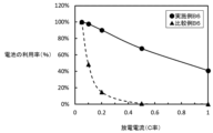
- Example B2 and Comparative Example B2 A high-rate discharge test was performed on each battery of Example B2 and Comparative Example B2.
- the conditions for the high-rate discharge test were as follows: under a 30°C environment, a cutoff voltage of 2.0 V to 5.0 V (vs. Na + /Na), a discharge rate of 0.1 C rate under 0.1 C rate charge, 0 .2C rate, 0.5C rate, and 1C rate were changed to obtain the utilization rate of the battery.
- the utilization rate represents the capacity ratio of each discharge rate with respect to the discharge capacity obtained by charging and discharging at the 0.1 C rate as 100%.
- FIG. 22 shows the relationship between the utilization rate and the discharge rate of Example B2 and Comparative Example B2. As is clear from FIG. 22, Example B2 is superior in output characteristics to Comparative Example B2.
- Example B1 and Comparative Example B1 A high rate charge test was performed on each battery of Example B1 and Comparative Example B1.
- the conditions for the high-rate charge test were as follows: under a 30°C environment, a cutoff voltage of 2.0 V to 5.0 V (vs. Li + /Li), a charge rate of 0.1 C rate under 0.1 C rate discharge, 0
- the charge rate of the battery was obtained by changing the rate of 2C, 0.5C, 1C, 2C, 3C and 6C.
- the charging rate represents the capacity ratio of each charging rate with respect to the capacity obtained by charging and discharging at a 0.1 C rate as 100%. That is, the larger the value, the better the input characteristics of the battery (the battery that can be fully charged in a short time).
- FIG. 23 shows the relationship between the charging rate and the charging rate of Example B1 and Comparative Example B1. As is clear from FIG. 23, Example B1 is superior in input characteristics to Comparative Example B1.
- Example B4 and Comparative Example B4 A high rate discharge test was performed on each battery of Example B4 and Comparative Example B4.
- the conditions for the high-rate discharge test were as follows: under a 30°C environment, a cutoff voltage of 0.001 V to 1.5 V (vs. Li + /Li), a discharge rate of 0.1 C rate under 0.1 C rate charge, 0
- the utilization rate of the battery was obtained by changing the 2C rate, 0.5C rate, 1C rate, 2C rate, 3C rate, 6C rate, 10C rate, 20C rate, and 30C rate.
- the utilization rate represents the capacity ratio of each discharge rate with respect to the discharge capacity obtained by charging and discharging at the 0.1 C rate as 100%. That is, the larger the numerical value, the higher the output of the battery.
- FIG. 24 shows the relationship between the utilization rate and the discharge rate of Example B4 and Comparative Example B4. As is clear from FIG. 24, Example B4 is superior in output characteristics to Comparative Example B4.
- Example B6 and Comparative Example B6 A high rate discharge test was performed on each battery of Example B6 and Comparative Example B6.
- the conditions for the high-rate discharge test were as follows: under a 30°C environment, a cutoff voltage of 0.001 V to 1.5 V (vs. K + /K), a discharge rate of 0.05 C rate under 0.05 C rate charge, 0
- the utilization rate of the battery was obtained by changing the rate of .1C, 0.2C, 0.5C and 1C.
- the utilization rate represents the capacity ratio of each discharge rate with respect to 100% of the discharge capacity obtained by charging and discharging at a rate of 0.05C. That is, the larger the numerical value, the higher the output of the battery.
- FIG. 25 shows the relationship between the utilization rate and the discharge rate of Example B6 and Comparative Example B6. As is clear from FIG. 25, Example B6 is superior in output characteristics to Comparative Example B6.
- Example B6 and Comparative Example B6 A high rate charge test was performed on each battery of Example B6 and Comparative Example B6.
- the conditions for the high-rate charge test are as follows: under a 30°C environment, a cutoff voltage of 0.001 V to 1.5 V (vs. K + /K), a charge rate of 0.05 C rate under 0.05 C rate discharge, 0 .
- the charge rate of the battery was obtained by changing the rate of 1C, 0.2C, 0.5C and 1C.
- the charging rate represents the capacity ratio of each charging rate with respect to the charging capacity obtained by charging and discharging at a rate of 0.05C as 100%. That is, the larger the numerical value, the better the input characteristics of the battery.
- FIG. 26 shows the relationship between the charging rate and the charging rate of Example B6 and Comparative Example B6. As is clear from FIG. 26, Example B6 is superior in input characteristics to Comparative Example B6.
- the graphite particles according to the present invention have a plane spacing d002 based on the diffraction peak corresponding to the lattice plane (002) measured by powder X-ray diffractometry of 0.3355 nm or more and 0.3370 nm or less.
- the particle diameter is 50 nm or more and 500 nm or less, and the value (average particle diameter) at which the integrated value of the number-based particle diameter distribution is 50% is defined as the secondary particle diameter (d50), and the secondary particle diameter (d50) is 0.15 ⁇ m.
- the specific surface area (BET) obtained from the nitrogen adsorption amount at 77K is 10 m 2 /g or more and 400 m 2 /g or less.
- the graphite particles of [1] above preferably include spherical particles, sheet-like particles, ribbon-like particles and cube-like particles.
- the graphite particles of [1] or [2] above are preferably obtained by heat-treating carbon particles obtained by electrolyzing carbon dioxide.
- the carbon particles include crystals having a secondary particle diameter (d50) of 100 nm or more and 200 nm or less and an interplanar spacing d002 of 0.3360 nm or more and 0.3373 nm or less, It is preferable that the specific surface area is 200 m 2 /g or more and 600 m 2 /g or less.
- the carbon particles preferably include spherical particles, sheet-like particles, ribbon-like particles, and cube-like particles.
- the electrode material for a non-aqueous secondary battery according to the present invention is an electrode material for a non-aqueous secondary battery, wherein the electrode material can reversibly occlude and release anions or cations.
- Graphite powder which is an aggregate of graphite particles according to any one of [1] to [5], is included as an active material.
- a non-aqueous secondary battery electrode according to the present invention is a non-aqueous secondary battery electrode in which the electrode material of [6] is provided on a current collector, wherein the current collector is copper , nickel, aluminum, titanium, tungsten, or stainless steel.
- a sealed non-aqueous secondary battery according to the present invention includes the electrode of [6] or [7] as a positive electrode, a negative electrode, or a bipolar electrode.
- the non-aqueous secondary battery of [8] above comprises a negative electrode capable of absorbing and releasing cations composed of alkali metal ions, a positive electrode capable of absorbing and releasing halogen-containing anions, and and a separator impregnated with the non-aqueous electrolyte, wherein the salt concentration in the non-aqueous electrolyte is reduced by charging.
- the alkali metal ions are preferably sodium ions or potassium ions.
- the non-aqueous secondary battery of [8] or [9] above is a non-aqueous secondary battery using a bipolar electrode in which an electrode material is provided on both sides of a current collector, and one side of the electrode It is preferable that one side functions as a positive electrode and the other side functions as a negative electrode.
- An electrical device according to the present invention is an electrical device using any one of the non-aqueous secondary batteries from [8] to [11] above.
- a method for producing graphite particles according to the present invention comprises the steps of: (a) preparing an electrolytic bath comprising a molten salt containing carbonate ions; (c) placing an anode in the electrolytic bath; and (d) generating an electrical discharge between the cathode and the electrolytic bath surface to reduce carbonate ions and produce carbon particles. (e) recovering the carbon particles together with the molten salt and removing the cooled and solidified salt by washing with water; (f) step (e). and graphitizing the carbon particles obtained in the above by heat treatment.
- the step of (a) preparing an electrolytic bath comprising a molten salt containing carbonate ions includes blowing carbon dioxide gas into the electrolytic bath containing a molten salt containing oxide ions. It is preferably done by
- the temperature of the surface of the electrolytic bath immediately below the cathode is preferably about 3000°C.
- the carbon particles have a secondary particle diameter (d50) of 100 nm or more and 200 nm or less, and a surface distance d002 of 0.3360 nm or more and 0.3373 nm. It preferably contains crystals having a specific surface area of 200 m 2 /g or more and 600 m 2 /g or less.
- the carbon particles preferably include spherical particles, sheet-like particles, ribbon-like particles, and cube-like particles.
- the heat treatment is preferably performed at a temperature of 2800°C or higher.
- the non-aqueous secondary battery obtained by the present invention is not limited to the carrier that contributes to the battery reaction of the above-described examples.
- the scope of the present invention is not limited to the above-described examples, and granulation, pulverization, sphering, and the like may be performed. Accordingly, such are also included within the scope of this invention.
Landscapes
- Chemical & Material Sciences (AREA)
- Chemical Kinetics & Catalysis (AREA)
- Electrochemistry (AREA)
- General Chemical & Material Sciences (AREA)
- Engineering & Computer Science (AREA)
- Inorganic Chemistry (AREA)
- Materials Engineering (AREA)
- Manufacturing & Machinery (AREA)
- Organic Chemistry (AREA)
- General Life Sciences & Earth Sciences (AREA)
- Geology (AREA)
- Life Sciences & Earth Sciences (AREA)
- Physics & Mathematics (AREA)
- Condensed Matter Physics & Semiconductors (AREA)
- General Physics & Mathematics (AREA)
- Battery Electrode And Active Subsutance (AREA)
Priority Applications (3)
| Application Number | Priority Date | Filing Date | Title |
|---|---|---|---|
| US18/699,013 US20250233150A1 (en) | 2021-10-08 | 2022-10-07 | Graphite particles |
| JP2023552982A JPWO2023058774A1 (https=) | 2021-10-08 | 2022-10-07 | |
| CN202280056508.6A CN117836241A (zh) | 2021-10-08 | 2022-10-07 | 石墨粒子 |
Applications Claiming Priority (2)
| Application Number | Priority Date | Filing Date | Title |
|---|---|---|---|
| JP2021166267 | 2021-10-08 | ||
| JP2021-166267 | 2021-10-08 |
Publications (1)
| Publication Number | Publication Date |
|---|---|
| WO2023058774A1 true WO2023058774A1 (ja) | 2023-04-13 |
Family
ID=85804400
Family Applications (1)
| Application Number | Title | Priority Date | Filing Date |
|---|---|---|---|
| PCT/JP2022/037738 Ceased WO2023058774A1 (ja) | 2021-10-08 | 2022-10-07 | 黒鉛粒子 |
Country Status (4)
| Country | Link |
|---|---|
| US (1) | US20250233150A1 (https=) |
| JP (1) | JPWO2023058774A1 (https=) |
| CN (1) | CN117836241A (https=) |
| WO (1) | WO2023058774A1 (https=) |
Cited By (1)
| Publication number | Priority date | Publication date | Assignee | Title |
|---|---|---|---|---|
| WO2025141658A1 (ja) * | 2023-12-25 | 2025-07-03 | 株式会社レゾナック | リチウムイオン二次電池用負極材、リチウムイオン二次電池用負極、リチウムイオン二次電池及びリチウムイオン二次電池用負極材の製造方法 |
Families Citing this family (1)
| Publication number | Priority date | Publication date | Assignee | Title |
|---|---|---|---|---|
| CN119852320B (zh) * | 2024-08-30 | 2026-01-13 | 宁德时代新能源科技股份有限公司 | 二次电池和用电装置 |
Citations (6)
| Publication number | Priority date | Publication date | Assignee | Title |
|---|---|---|---|---|
| JPH05159773A (ja) * | 1991-12-04 | 1993-06-25 | Fuji Elelctrochem Co Ltd | リチウム二次電池 |
| JPH1087311A (ja) * | 1996-09-10 | 1998-04-07 | Mitsubishi Electric Corp | 黒鉛微粒子およびその製造法並びにそれを用いたリチウム電池 |
| JPH10188993A (ja) * | 1996-12-24 | 1998-07-21 | Ricoh Co Ltd | 非水電解質二次電池 |
| JP2008050245A (ja) * | 2006-08-25 | 2008-03-06 | Nippon Carbon Co Ltd | 人造黒鉛微粉末の製造法および人造黒鉛微粉末。 |
| JP2010053425A (ja) * | 2008-08-29 | 2010-03-11 | Doshisha | 二酸化炭素中の炭素の固定方法 |
| JP2016191153A (ja) * | 2010-11-02 | 2016-11-10 | 学校法人同志社 | シリコンナノ粒子の製造方法 |
-
2022
- 2022-10-07 JP JP2023552982A patent/JPWO2023058774A1/ja active Pending
- 2022-10-07 US US18/699,013 patent/US20250233150A1/en active Pending
- 2022-10-07 CN CN202280056508.6A patent/CN117836241A/zh active Pending
- 2022-10-07 WO PCT/JP2022/037738 patent/WO2023058774A1/ja not_active Ceased
Patent Citations (6)
| Publication number | Priority date | Publication date | Assignee | Title |
|---|---|---|---|---|
| JPH05159773A (ja) * | 1991-12-04 | 1993-06-25 | Fuji Elelctrochem Co Ltd | リチウム二次電池 |
| JPH1087311A (ja) * | 1996-09-10 | 1998-04-07 | Mitsubishi Electric Corp | 黒鉛微粒子およびその製造法並びにそれを用いたリチウム電池 |
| JPH10188993A (ja) * | 1996-12-24 | 1998-07-21 | Ricoh Co Ltd | 非水電解質二次電池 |
| JP2008050245A (ja) * | 2006-08-25 | 2008-03-06 | Nippon Carbon Co Ltd | 人造黒鉛微粉末の製造法および人造黒鉛微粉末。 |
| JP2010053425A (ja) * | 2008-08-29 | 2010-03-11 | Doshisha | 二酸化炭素中の炭素の固定方法 |
| JP2016191153A (ja) * | 2010-11-02 | 2016-11-10 | 学校法人同志社 | シリコンナノ粒子の製造方法 |
Cited By (1)
| Publication number | Priority date | Publication date | Assignee | Title |
|---|---|---|---|---|
| WO2025141658A1 (ja) * | 2023-12-25 | 2025-07-03 | 株式会社レゾナック | リチウムイオン二次電池用負極材、リチウムイオン二次電池用負極、リチウムイオン二次電池及びリチウムイオン二次電池用負極材の製造方法 |
Also Published As
| Publication number | Publication date |
|---|---|
| CN117836241A (zh) | 2024-04-05 |
| JPWO2023058774A1 (https=) | 2023-04-13 |
| US20250233150A1 (en) | 2025-07-17 |
Similar Documents
| Publication | Publication Date | Title |
|---|---|---|
| Hu et al. | Ti 2 Nb 2x O 4+ 5x anode materials for lithium-ion batteries: a comprehensive review | |
| Wang et al. | Comprehensive new insights and perspectives into Ti‐based anodes for next‐generation alkaline metal (Na+, K+) ion batteries | |
| Massé et al. | Beyond Li-ion: electrode materials for sodium-and magnesium-ion batteries | |
| Li et al. | Application of expanded graphite-based materials for rechargeable batteries beyond lithium-ions | |
| Xu et al. | Facile synthesis of hierarchical micro/nanostructured MnO material and its excellent lithium storage property and high performance as anode in a MnO/LiNi0. 5Mn1. 5O4-δ lithium ion battery | |
| JP5812482B2 (ja) | ナトリウム二次電池、ナトリウム二次電池用負極の製造方法および電気機器 | |
| Fang et al. | Free-standing LiNi0. 5Mn1. 5O4/carbon nanofiber network film as lightweight and high-power cathode for lithium ion batteries | |
| JP6119021B2 (ja) | ナトリウム二次電池用負極材料及びその製造方法、並びにナトリウム二次電池用負極及びナトリウム二次電池 | |
| CN107845781B (zh) | 锂离子二次电池用负极活性材料、其制备方法及锂离子二次电池 | |
| Jiang et al. | A novel CoO hierarchical morphologies on carbon nanofiber for improved reversibility as binder-free anodes in lithium/sodium ion batteries | |
| CN109553080B (zh) | 锂离子电池负极活性材料、锂离子电池负极、锂离子电池、电池组及电池动力车 | |
| Zhang et al. | Li3V2 (PO4) 3@ C/graphene composite with improved cycling performance as cathode material for lithium-ion batteries | |
| CN104428255B (zh) | 掺杂的镍酸盐化合物 | |
| US20180219214A1 (en) | Exfoliated Graphite Worm-Protected Metal Fluoride and Metal Chloride Cathode Active Materials for Lithium Batteries | |
| CN103165874A (zh) | 一种锂离子电池多孔硅负极材料及其制备方法和用途 | |
| CN102723479A (zh) | 镁二次电池用正极活性物质及镁二次电池 | |
| CN106207119B (zh) | 一种制备氮掺杂多孔球形无序碳材料的方法 | |
| JP6297746B2 (ja) | 電池電極用炭素質成形体、及びその製造方法 | |
| JP2013196978A (ja) | ナトリウム二次電池用正極材料及びその製造方法、並びにナトリウム二次電池用正極、ナトリウム二次電池及びこれを用いた電気機器 | |
| WO2023058774A1 (ja) | 黒鉛粒子 | |
| JP5765780B2 (ja) | リチウムシリケート系化合物とリチウムイオン二次電池用正極活物質及びこれを用いたリチウムイオン二次電池 | |
| JP6220365B2 (ja) | 蓄電デバイスの電極用チタン酸リチウム粉末および活物質材料、並びにそれを用いた電極シートおよび蓄電デバイス | |
| Zhu et al. | Enabling High‐Performance Electrode Materials for Potassium‐Ion Batteries: Ionic Transport, Size and Electro–Chemo–Mechanical Effects | |
| Roy et al. | Nanomaterials for Electrochemical energy Storage devices | |
| Li et al. | Carbon/tin oxide composite electrodes for improved lithium-ion batteries |
Legal Events
| Date | Code | Title | Description |
|---|---|---|---|
| 121 | Ep: the epo has been informed by wipo that ep was designated in this application |
Ref document number: 22878641 Country of ref document: EP Kind code of ref document: A1 |
|
| WWE | Wipo information: entry into national phase |
Ref document number: 2023552982 Country of ref document: JP |
|
| WWE | Wipo information: entry into national phase |
Ref document number: 202280056508.6 Country of ref document: CN |
|
| WWE | Wipo information: entry into national phase |
Ref document number: 18699013 Country of ref document: US |
|
| NENP | Non-entry into the national phase |
Ref country code: DE |
|
| 122 | Ep: pct application non-entry in european phase |
Ref document number: 22878641 Country of ref document: EP Kind code of ref document: A1 |
|
| WWP | Wipo information: published in national office |
Ref document number: 18699013 Country of ref document: US |