WO2023058592A1 - 水処理方法および水処理システム - Google Patents
水処理方法および水処理システム Download PDFInfo
- Publication number
- WO2023058592A1 WO2023058592A1 PCT/JP2022/036916 JP2022036916W WO2023058592A1 WO 2023058592 A1 WO2023058592 A1 WO 2023058592A1 JP 2022036916 W JP2022036916 W JP 2022036916W WO 2023058592 A1 WO2023058592 A1 WO 2023058592A1
- Authority
- WO
- WIPO (PCT)
- Prior art keywords
- solution
- draw solution
- draw
- membrane
- forward osmosis
- Prior art date
Links
- XLYOFNOQVPJJNP-UHFFFAOYSA-N water Substances O XLYOFNOQVPJJNP-UHFFFAOYSA-N 0.000 title claims abstract description 108
- 238000000034 method Methods 0.000 title claims abstract description 53
- 239000012528 membrane Substances 0.000 claims abstract description 142
- 239000000243 solution Substances 0.000 claims abstract description 140
- 238000009292 forward osmosis Methods 0.000 claims abstract description 77
- 238000000926 separation method Methods 0.000 claims abstract description 73
- 239000012527 feed solution Substances 0.000 claims abstract description 48
- 238000005191 phase separation Methods 0.000 claims abstract description 30
- 238000001816 cooling Methods 0.000 claims abstract description 22
- 230000007423 decrease Effects 0.000 claims abstract description 17
- 239000000110 cooling liquid Substances 0.000 claims description 18
- 239000013535 sea water Substances 0.000 claims description 18
- 239000007788 liquid Substances 0.000 claims description 13
- 238000010438 heat treatment Methods 0.000 claims description 10
- 239000012141 concentrate Substances 0.000 claims description 9
- 230000003204 osmotic effect Effects 0.000 claims description 9
- 239000012071 phase Substances 0.000 description 18
- 238000001223 reverse osmosis Methods 0.000 description 16
- 238000001728 nano-filtration Methods 0.000 description 15
- 239000011347 resin Substances 0.000 description 13
- 229920005989 resin Polymers 0.000 description 13
- 239000000463 material Substances 0.000 description 12
- 230000007704 transition Effects 0.000 description 11
- 229920000208 temperature-responsive polymer Polymers 0.000 description 10
- 238000010586 diagram Methods 0.000 description 7
- VYPSYNLAJGMNEJ-UHFFFAOYSA-N Silicium dioxide Chemical compound O=[Si]=O VYPSYNLAJGMNEJ-UHFFFAOYSA-N 0.000 description 6
- 229920002301 cellulose acetate Polymers 0.000 description 4
- 229920000642 polymer Polymers 0.000 description 4
- 238000000108 ultra-filtration Methods 0.000 description 4
- 239000004695 Polyether sulfone Substances 0.000 description 3
- QYKIQEUNHZKYBP-UHFFFAOYSA-N Vinyl ether Chemical compound C=COC=C QYKIQEUNHZKYBP-UHFFFAOYSA-N 0.000 description 3
- 239000011557 critical solution Substances 0.000 description 3
- 230000000694 effects Effects 0.000 description 3
- 239000012510 hollow fiber Substances 0.000 description 3
- 229920002492 poly(sulfone) Polymers 0.000 description 3
- 229920002647 polyamide Polymers 0.000 description 3
- 229920006393 polyether sulfone Polymers 0.000 description 3
- 239000011148 porous material Substances 0.000 description 3
- 239000000047 product Substances 0.000 description 3
- 239000000377 silicon dioxide Substances 0.000 description 3
- 239000004952 Polyamide Substances 0.000 description 2
- 239000004372 Polyvinyl alcohol Substances 0.000 description 2
- 229920002678 cellulose Polymers 0.000 description 2
- 239000001913 cellulose Substances 0.000 description 2
- 239000012461 cellulose resin Substances 0.000 description 2
- 238000010612 desalination reaction Methods 0.000 description 2
- 125000001165 hydrophobic group Chemical group 0.000 description 2
- 238000005374 membrane filtration Methods 0.000 description 2
- 239000012782 phase change material Substances 0.000 description 2
- -1 polyoxypropylene Polymers 0.000 description 2
- 229920002451 polyvinyl alcohol Polymers 0.000 description 2
- 229920001289 polyvinyl ether Polymers 0.000 description 2
- 150000003839 salts Chemical class 0.000 description 2
- 238000011144 upstream manufacturing Methods 0.000 description 2
- 239000002918 waste heat Substances 0.000 description 2
- 229920002284 Cellulose triacetate Polymers 0.000 description 1
- ZAMOUSCENKQFHK-UHFFFAOYSA-N Chlorine atom Chemical compound [Cl] ZAMOUSCENKQFHK-UHFFFAOYSA-N 0.000 description 1
- CERQOIWHTDAKMF-UHFFFAOYSA-N Methacrylic acid Chemical compound CC(=C)C(O)=O CERQOIWHTDAKMF-UHFFFAOYSA-N 0.000 description 1
- 229920003171 Poly (ethylene oxide) Polymers 0.000 description 1
- 229920012266 Poly(ether sulfone) PES Polymers 0.000 description 1
- NNLVGZFZQQXQNW-ADJNRHBOSA-N [(2r,3r,4s,5r,6s)-4,5-diacetyloxy-3-[(2s,3r,4s,5r,6r)-3,4,5-triacetyloxy-6-(acetyloxymethyl)oxan-2-yl]oxy-6-[(2r,3r,4s,5r,6s)-4,5,6-triacetyloxy-2-(acetyloxymethyl)oxan-3-yl]oxyoxan-2-yl]methyl acetate Chemical compound O([C@@H]1O[C@@H]([C@H]([C@H](OC(C)=O)[C@H]1OC(C)=O)O[C@H]1[C@@H]([C@@H](OC(C)=O)[C@H](OC(C)=O)[C@@H](COC(C)=O)O1)OC(C)=O)COC(=O)C)[C@@H]1[C@@H](COC(C)=O)O[C@@H](OC(C)=O)[C@H](OC(C)=O)[C@H]1OC(C)=O NNLVGZFZQQXQNW-ADJNRHBOSA-N 0.000 description 1
- 125000002777 acetyl group Chemical group [H]C([H])([H])C(*)=O 0.000 description 1
- 238000004220 aggregation Methods 0.000 description 1
- 230000002776 aggregation Effects 0.000 description 1
- 125000003172 aldehyde group Chemical group 0.000 description 1
- PNEYBMLMFCGWSK-UHFFFAOYSA-N aluminium oxide Inorganic materials [O-2].[O-2].[O-2].[Al+3].[Al+3] PNEYBMLMFCGWSK-UHFFFAOYSA-N 0.000 description 1
- 150000001408 amides Chemical class 0.000 description 1
- 150000001412 amines Chemical class 0.000 description 1
- 239000007864 aqueous solution Substances 0.000 description 1
- 229920001400 block copolymer Polymers 0.000 description 1
- 125000003178 carboxy group Chemical group [H]OC(*)=O 0.000 description 1
- 239000000919 ceramic Substances 0.000 description 1
- 229910052801 chlorine Inorganic materials 0.000 description 1
- 239000000460 chlorine Substances 0.000 description 1
- 230000006837 decompression Effects 0.000 description 1
- 230000003247 decreasing effect Effects 0.000 description 1
- 230000018044 dehydration Effects 0.000 description 1
- 238000006297 dehydration reaction Methods 0.000 description 1
- 239000000645 desinfectant Substances 0.000 description 1
- MTHSVFCYNBDYFN-UHFFFAOYSA-N diethylene glycol Chemical compound OCCOCCO MTHSVFCYNBDYFN-UHFFFAOYSA-N 0.000 description 1
- 238000010790 dilution Methods 0.000 description 1
- 239000012895 dilution Substances 0.000 description 1
- 238000005265 energy consumption Methods 0.000 description 1
- 238000005516 engineering process Methods 0.000 description 1
- RTZKZFJDLAIYFH-UHFFFAOYSA-N ether Chemical group CCOCC RTZKZFJDLAIYFH-UHFFFAOYSA-N 0.000 description 1
- 239000013505 freshwater Substances 0.000 description 1
- 125000002887 hydroxy group Chemical group [H]O* 0.000 description 1
- 239000000819 hypertonic solution Substances 0.000 description 1
- 229940021223 hypertonic solution Drugs 0.000 description 1
- 230000006698 induction Effects 0.000 description 1
- 239000010842 industrial wastewater Substances 0.000 description 1
- 239000002608 ionic liquid Substances 0.000 description 1
- 150000002500 ions Chemical class 0.000 description 1
- 239000007791 liquid phase Substances 0.000 description 1
- 238000004519 manufacturing process Methods 0.000 description 1
- 244000005700 microbiome Species 0.000 description 1
- 239000000178 monomer Substances 0.000 description 1
- 125000006353 oxyethylene group Chemical group 0.000 description 1
- 239000012466 permeate Substances 0.000 description 1
- 229920001983 poloxamer Polymers 0.000 description 1
- 229920001451 polypropylene glycol Polymers 0.000 description 1
- 229920002689 polyvinyl acetate Polymers 0.000 description 1
- 239000011118 polyvinyl acetate Substances 0.000 description 1
- 230000004043 responsiveness Effects 0.000 description 1
- 230000002441 reversible effect Effects 0.000 description 1
- 230000000630 rising effect Effects 0.000 description 1
- 239000002904 solvent Substances 0.000 description 1
- 238000003860 storage Methods 0.000 description 1
- 239000000126 substance Substances 0.000 description 1
Images


Classifications
-
- B—PERFORMING OPERATIONS; TRANSPORTING
- B01—PHYSICAL OR CHEMICAL PROCESSES OR APPARATUS IN GENERAL
- B01D—SEPARATION
- B01D61/00—Processes of separation using semi-permeable membranes, e.g. dialysis, osmosis or ultrafiltration; Apparatus, accessories or auxiliary operations specially adapted therefor
-
- C—CHEMISTRY; METALLURGY
- C02—TREATMENT OF WATER, WASTE WATER, SEWAGE, OR SLUDGE
- C02F—TREATMENT OF WATER, WASTE WATER, SEWAGE, OR SLUDGE
- C02F1/00—Treatment of water, waste water, or sewage
- C02F1/44—Treatment of water, waste water, or sewage by dialysis, osmosis or reverse osmosis
-
- Y—GENERAL TAGGING OF NEW TECHNOLOGICAL DEVELOPMENTS; GENERAL TAGGING OF CROSS-SECTIONAL TECHNOLOGIES SPANNING OVER SEVERAL SECTIONS OF THE IPC; TECHNICAL SUBJECTS COVERED BY FORMER USPC CROSS-REFERENCE ART COLLECTIONS [XRACs] AND DIGESTS
- Y02—TECHNOLOGIES OR APPLICATIONS FOR MITIGATION OR ADAPTATION AGAINST CLIMATE CHANGE
- Y02A—TECHNOLOGIES FOR ADAPTATION TO CLIMATE CHANGE
- Y02A20/00—Water conservation; Efficient water supply; Efficient water use
- Y02A20/124—Water desalination
- Y02A20/131—Reverse-osmosis
Definitions
- the present invention relates to a water treatment method and a water treatment system.
- the forward osmosis (FO) phenomenon is a phenomenon in which the solvent (such as water) in the low-concentration side solution (feed solution: FS) moves toward the high-concentration side solution (draw solution: DS). That is.
- Membrane separation processes such as reverse osmosis apply artificially high pressure to a high-concentration target solution to separate a high-concentration target solution (seawater, etc.) It is a process to move water to the side. This allows, for example, the production of water from the subject solution. Since the membrane separation process requires high pressure, the energy consumption is very high and the energy efficiency is low. Therefore, in recent years, in order to improve the energy efficiency of water treatment, a desalination method using a forward osmosis process that does not require artificial pressure has been studied.
- Patent Document 1 Japanese Patent Publication No. 2014-512951 discloses a water treatment method including forward osmosis treatment using a draw solute whose solubility is reduced by heating (temperature increase).
- this low-concentration draw solution, high-concentration draw solution, etc. can be reused as a regenerated draw solution (regenerated DS).
- regenerated DS regenerated draw solution
- heat exchange heats the liquid to be subjected to the phase separation treatment and cools the regenerated DS at the same time. Therefore, the energy cost required for cooling the regenerated DS can be reduced compared to the case where a separate cooling device for the regenerated DS is provided.
- Patent Document 3 Japanese Patent Application Laid-Open No. 2019-141812 discloses heat exchange between FS (concentrated FS) concentrated by the FO module and regenerated DS. Also in this case, the energy cost required for cooling the regenerated DS can be reduced compared to the case where a separate cooling device for the regenerated DS is provided.
- the concentrated FS used for cooling the regenerated DS is heat-exchanged between the raw seawater and the regenerated DS in the forward osmosis membrane module, so the temperature is higher than that of the raw seawater.
- the amount of concentrated FS decreases, so the temperature is enough to supply the membrane.
- an object of the present invention is to provide a water treatment method and method for recovering water from a feed solution to a draw solution by forward osmosis, and recovering water from the draw solution from which the water is recovered by phase separation and membrane separation.
- a forward osmosis process and a phase separation step of separating the draw solution into a low-concentration draw solution and a high-concentration draw solution by increasing the temperature of the draw solution after the forward osmosis step; a membrane separation step of separating the low concentration draw solution into water and a concentrate containing the draw solute using a separation membrane;
- the temperature of the membrane separation step is higher than the temperature of the forward osmosis step, reusing a regenerated draw solution, which is at least a portion of at least one of the concentrated draw solution and the concentrated liquid, as the draw solution after being cooled by heat exchange with a cooling liquid; at least a liquid other than the dilute draw solution and the concentrated feed solution is used as the cooling liquid; water treatment method.
- the feed solution is seawater;
- a water treatment method and a water treatment system water is recovered from a feed solution to a draw solution by forward osmosis, and water is recovered from the draw solution from which water is recovered by phase separation and membrane separation,
- the draw solution whose temperature has been raised by the phase separation process is reused as the regenerated draw solution, the regenerated draw solution can be sufficiently cooled before reuse.
- FIG. 1 is a schematic diagram showing an example of a water treatment system according to Embodiment 1.
- FIG. FIG. 2 is a schematic diagram showing an example of a water treatment system according to Embodiment 2;
- FIG. 10 is a schematic diagram showing an example of a water treatment system according to Embodiment 3;
- FIG. 10 is a schematic diagram showing another example of the water treatment system according to Embodiment 3;
- the water treatment method of the present invention is a method for separating water from a feed solution (liquid containing water and components other than water).
- Feed solutions include, for example, seawater, river water, lake water, industrial wastewater, and the like.
- the water treatment method of the present invention includes at least a forward osmosis process, a phase separation process, and a membrane separation process, which will be described below.
- forward osmosis process In the forward osmosis process, one side of the forward osmosis membrane is contacted with a feed solution containing water and non-water components, while the other side of the forward osmosis membrane is exposed to a draw solute whose solubility decreases with increasing temperature. contact with solution. This causes the water contained in the feed solution to move through the forward osmosis membrane into the draw solution.
- the forward osmosis membrane is not particularly limited, and various membranes that can be used for forward osmosis can be used.
- semipermeable membranes examples include reverse osmosis membranes (RO membranes), forward osmosis membranes (FO membranes), nanofiltration membranes (NF membranes), ultrafiltration membranes (UF membranes), : Ultrafiltration Membrane).
- the semipermeable membrane is preferably a reverse osmosis membrane, a forward osmosis membrane, or a nanofiltration membrane.
- the pressure of the feed solution in the first chamber is preferably 0.01 to 10 MPa.
- the pore size of RO membranes and FO membranes is about 2 nm or less, and the pore size of UF membranes is about 2 to 100 nm.
- the NF membrane has a relatively low rejection rate of ions and salts, and the pore size of the NF membrane is usually about 1 to 2 nm.
- the salt removal rate of the RO membrane, FO membrane, or NF membrane is preferably 90% or more.
- the material constituting the semipermeable membrane is not particularly limited, but examples thereof include cellulose-based resins, polysulfone-based resins, and polyamide-based resins.
- the semipermeable membrane is preferably made of a material containing at least one of cellulose resin and polysulfone resin.
- the cellulose resin is preferably cellulose acetate resin.
- Cellulose acetate-based resins are resistant to chlorine, which is a disinfectant, and have the characteristic of being able to suppress the growth of microorganisms.
- the cellulose acetate-based resin is preferably cellulose acetate, and more preferably cellulose triacetate from the viewpoint of durability.
- Examples of the cellulose-based semipermeable membrane include CTA (manufactured by Toyobo Co., Ltd.).
- the polysulfone-based resin is preferably a polyethersulfone-based resin.
- the polyethersulfone-based resin is preferably sulfonated polyethersulfone.
- the shape of the semipermeable membrane is not particularly limited, but examples thereof include a flat membrane, a spiral membrane and a hollow fiber membrane.
- Hollow fiber membranes (hollow fiber type semipermeable membranes) have smaller membrane thickness than spiral type semipermeable membranes, etc., and can increase the membrane area per module, which can increase the permeation efficiency.
- the draw solute used in the present invention is not particularly limited as long as it is a substance whose solubility decreases with increasing temperature. It should be noted that such a decrease in solubility is reversible, and conversely, if the temperature decreases, it is preferable that the solubility increases.
- Such draw solutes include, for example, LCST (lower critical solution temperature) type phase transition materials.
- LCST lower critical solution temperature
- an aqueous solution containing an LCST-type phase transition material undergoes dehydration of the solute as the temperature of the solution rises, and temperature phase transition (liquid-liquid phase separation) occurs due to aggregation of the solute molecules.
- temperature phase transition liquid-liquid phase separation
- polymolecular associations are formed even in the temperature range below the phase transition temperature (homogeneous phase region below the LCST curve)
- the osmotic pressure of the solution increases due to the temperature rise. is expected to decrease.
- LCST-type phase transition materials include LCST-type temperature-responsive polymers.
- the LCST-type temperature-responsive polymer dissolves in water at relatively low temperatures, and when the temperature rises above a predetermined temperature (specific lower critical solution temperature: LCST), a dilute phase (low-concentration draw solution) and a dense phase (high concentration draw solution) and phase separation.
- LCST specific lower critical solution temperature
- a dilute phase low-concentration draw solution
- dense phase high concentration draw solution
- the LCST-type thermoresponsive polymer preferably has at least one hydrophilic group in at least some or all structural units (monomer units). Moreover, the temperature-responsive polymer may have a hydrophobic group in some structural units while having a hydrophilic group. In order for the temperature-responsive polymer to have temperature-responsiveness, it is considered that the balance between the hydrophilic groups and the hydrophobic groups contained in the molecule is important.
- hydrophilic groups include hydroxyl groups, carboxyl groups, acetyl groups, aldehyde groups, ether bonds, and ester bonds.
- temperature-responsive polymers include polyvinyl ether-based polymers, polyvinyl acetate-based polymers, and (meth)acrylic acid-based polymers.
- Polyvinyl ether-based polymers include polymethyl vinyl ether, vinyl ether having an oxyethylene chain, and polyhydroxybutyl vinyl ether.
- LCST-type temperature-responsive polymer products examples include Pluronic (registered trademark) (manufactured by BASF), which is a block copolymer of polyoxypropylene and polyoxyethylene.
- LCST-type phase transition materials other than LCST-type temperature-responsive polymers include LCST-type ionic liquids, glycol ether-based LCST-type phase-change materials, acid amide-based LCST-type phase-change materials, and amine-based LCST-type phase transition materials.
- a phase transition material etc. are mentioned.
- Patent Document 2 International Publication No. 2018/150690
- thermo-responsive draw solution changes with temperature (e.g., decreases with temperature rise).
- the osmotic pressure of the draw solution (after raising the temperature) to be subjected to the membrane separation step is preferably 0.01 to 2 MPa, more preferably 0.01 to 1 MPa.
- a feed solution (FS) is allowed to flow into a first chamber 11 provided in contact with one surface of a forward osmosis membrane 10, and the FS is passed through the forward osmosis membrane. 10 is brought into contact with one side.
- a draw solution (DS) containing a draw solute is allowed to flow into the second chamber 12 provided in contact with the other surface of the forward osmosis membrane 10, and the DS is brought into contact with the other surface of the forward osmosis membrane 10.
- the temperature of the forward osmosis step (the temperature of the FS solution at the inlet of the first chamber 11 and the temperature of the DS at the inlet in the second chamber 12) is preferably less than 40°C, more preferably 20-35 °C.
- Phase separation step In the phase separation step, after the forward osmosis step, the temperature of the draw solution is increased to separate the draw solution into a low-concentration draw solution (low-concentration DS) and a high-concentration draw solution (high-concentration DS) (phase separation). do.
- low-concentration draw solution low-concentration draw solution
- high-concentration draw solution high-concentration draw solution
- the temperature of the draw solution after rising in the phase separation step is preferably 40°C or higher and 95°C or lower, more preferably 40°C or higher and 90°C or lower, and still more preferably 40°C or higher and 85°C or lower.
- the draw solution containing water in the feed solution is flowed into the separation tank 3, where the temperature of the draw solution is raised to separate it into a dilute phase (low-concentration draw solution) and a rich phase (high-concentration draw solution).
- the temperature of the draw solution is raised above the LCST to separate the dilute phase (low-concentration DS) and the rich phase (high-concentration DS). can be done.
- the separation tank 3 preferably has a heating mechanism.
- a heating mechanism such as a heat exchanger may be provided upstream of the separation tank 3 in order to raise the temperature of the draw solution.
- a separation membrane In the membrane separation process, a separation membrane is used to separate a low-concentration draw solution (low-concentration DS) into water and a concentrate containing a draw solute using a pressure difference due to pressurization, decompression, or the like as a driving force.
- a separation membrane for example, a UF membrane, an NF membrane, an RO membrane, or the like can be used.
- the temperature of the membrane separation process is preferably higher than the temperature of the forward osmosis process. Also, a temperature lower than the phase separation temperature is preferred.
- the temperature in the membrane separation step is more preferably 40°C or higher and 95°C or lower, still more preferably 40°C or higher and 90°C or lower, and even more preferably 40°C or higher and 85°C or lower.
- At least one of the high-concentration DS containing a large amount of draw solute generated in the phase separation step and the concentrate (concentrated low-concentration DS) containing the draw solute generated in the membrane separation step is used for forward osmosis. Recycled as draw solution. At least a portion of the highly concentrated draw solution and/or the concentrated solution that is recycled in this manner is referred to herein as a "regenerated draw solution.”
- the regenerated draw solution (regenerated DS) is reused as the draw solution after being cooled by heat exchange with the cooling liquid.
- the regenerated DS has a high temperature due to the temperature rise in the phase separation process, but it must be cooled below the heat-resistant temperature of the FO module 1 used in the forward osmosis process, for example.
- the DS is regenerated to a temperature at which a sufficient osmotic pressure can be obtained before reuse. Must be cooled.
- the cooling liquid used for cooling (heat exchange) of the regenerated DS.
- the cooling liquid is preferably a liquid that has a higher cooling efficiency (lower temperature) than the dilute draw solution and the concentrated feed solution. In this case, the cooling efficiency of the regenerated DS is improved as compared with the conventional one, and the regenerated DS can be sufficiently cooled before reuse.
- At least seawater is preferably used as the cooling liquid (liquid other than the diluted draw solution and the concentrated feed solution).
- Seawater is typically cooler than the dilute draw solution and the concentrated feed solution, and therefore has a higher cooling efficiency than the dilute draw solution and the concentrated feed solution.
- the seawater that has been used to cool the regenerated DS in the heat exchanger 7 may be discharged to the ocean or the like, but may be supplied to the first chamber 11 of the FO module 1 as shown in FIG. preferable.
- the seawater used to cool the regenerated DS has a higher temperature than the original seawater, but this increases the osmotic pressure and decreases the viscosity, resulting in an overall increase in the amount of permeated water. This is because the effect of
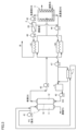
- FIG. 1 is a schematic diagram showing an example of a water treatment system according to Embodiment 1.
- FIG. 1 is a schematic diagram showing an example of a water treatment system according to Embodiment 1.
- the water treatment system of this embodiment used in the above water treatment method includes: A forward osmosis membrane 10, a first chamber 11 provided for contacting one side of the forward osmosis membrane 10 with a feed solution, and a first chamber 11 provided for contacting the other side of the forward osmosis membrane with a draw solution.
- a forward osmosis module 1 comprising two chambers 12; a separation tank 3 having a heating mechanism for separating the draw solution into a low-concentration draw solution and a high-concentration draw solution by increasing the temperature of the draw solution; a separation membrane 20 (separation membrane module 2) for separating a low-concentration draw solution into water and a draw solute; a heat exchanger 7 for cooling the regenerated draw solution.
- pumps 41 to 46 cause FS, DS, water, etc. to flow in the directions of the arrows.
- the pump 45 is normally a high-pressure pump.
- the separation tank 3 has a heating mechanism. That is, hot water such as waste heat water is supplied around the separation tank 3 in order to raise the temperature of the diluted DS supplied to the separation tank 3 and cause phase separation. Thus, in the phase separation process performed in the separation tank 3, heat energy is required to raise the temperature of the draw solution. It is possible to suppress the increase in cost due to The temperature of the hot water may be adjusted according to the target value of the temperature after the DS rise in the phase separation step.
- the draw solution (diluted DS) undergoes phase separation into low-concentration DS and high-concentration DS due to the temperature rise.
- the high-concentration DS separated in the separation tank 3 and the low-concentration DS (concentrate) concentrated in the separation membrane module 2 are sent to the tank 5 by, for example, a pump 44 and temporarily stored. After that, it is reused as a DS for the forward osmosis process.
- the embodiment is not limited to that shown in FIG. 1, and either the high-concentration DS or the concentrated liquid may be reused as the DS in the forward osmosis process. Also, at least one of the high-concentration DS and the concentrated liquid may be reused entirely or partly. That is, at least a portion of at least one of the high-concentration DS and the concentrated liquid is reused as the DS in the forward osmosis process.
- the temporary storage in the tank 5 shown in FIG. may be connected by
- the regenerated DS (at least a portion of the concentrated draw solution and/or the concentrate) is fed to the forward osmosis module 1 in the heat exchanger 7 before being supplied to the FS (e.g. After being cooled by heat exchange with sea water, it is reused as a DS draw solution.
- the FS (for example, seawater) may be used entirely or only partially for cooling the regenerated DS.
- the separation membrane 20 for separating the low-concentration draw solution into water and the draw solute
- UF membrane Ultrafiltration Membrane
- NF membrane Nanofiltration Membrane
- RO membrane Reverse Osmosis Membrane
- the separation membrane module preferably has heat resistance at high temperatures (eg, 40°C or higher). This is to enable the membrane separation process to be performed on the high-temperature, low-concentration DS discharged from the separation tank 3 .
- the amount of concentrated FS used as the cooling liquid may exceed the amount of FS (for example, seawater) simultaneously used as the cooling liquid.
- heat-resistant separation membrane materials include polyethersulfone (PES)-based resins, polyamide (PA)-based resins, and polyvinyl alcohol (PVA)-based resins.
- PES polyethersulfone
- PA polyamide
- PVA polyvinyl alcohol
- parts other than the separation membrane also have heat resistance, and it is preferable that the separation membrane module has heat resistance as a whole.
- heat-resistant separation membrane module products include Thermoplus (manufactured by Nitto Denko Corporation), Durathermo (manufactured by GE Water Technologies), Romembra (registered trademark) TS series (manufactured by Toray Industries, Inc.), and the like. mentioned.
- heat-resistant separation membranes include, for example, ceramics such as alumina and silica.
- silica for heat-resistant membranes include silica derived from bistriylethoxysilylethane (Noryo Tsuru, "Development of Robust RO/NF Membrane Compatible with Various Water Sources", Journal of Japan Society of Water Environment, vol. 36(A), No.1, pp.8-10, 2013).
- FIG. 2 is a schematic diagram showing an example of a water treatment system according to Embodiment 2.
- the water treatment system shown in FIG. 2 further includes a heat exchanger 8 in addition to the water treatment system of Embodiment 1 shown in FIG. As shown in FIG. 2, the heat exchanger 8 uses concentrated FS as the cooling liquid.
- FIG. 3 is a schematic diagram showing an example of a water treatment system according to Embodiment 3.
- the water treatment system of Embodiment 3 shown in FIG. 3 further includes heat exchangers 61 and 62 in addition to the water treatment system of Embodiment 1 shown in FIG. As shown in FIG. 3, the heat exchangers 61 and 62 use diluted DS as the cooling liquid.
- the temperature of the finally obtained water is reduced by cooling the water with the heat exchanger 61. can be lowered to the desired temperature.
- the waste heat of the regenerated DS (low-concentration DS and high-concentration DS) discharged from the separation tank 3 is used to dilute the diluted DS supplied to the separation tank 3 through heat exchange in the heat exchangers 61 and 62. Since it can be heated, the thermal energy required for the phase separation process can be reduced, and the energy efficiency of water treatment can be increased.
- the separation membrane module 2 (separation membrane 20) is arranged upstream of the heat exchanger 61.
- the high-temperature low-concentration DS discharged from the separation tank 3 is subjected to the membrane separation process.
- the membrane separation process is carried out for such a high-temperature DS, the water permeation efficiency is high, so the pressure of the pump required for the membrane separation process is low, so the energy required for the pump is reduced, and the energy for water treatment An effect of improving efficiency is expected.
- the separation membrane module 2 (separation membrane 20) must have heat resistance at high temperatures (for example, 40° C. or higher).
- the separation membrane module 2 may be provided downstream of the heat exchanger 61, as shown in FIG. In this case, in the separation membrane module 2 , the membrane separation process is performed on the low-concentration DS after the temperature has been lowered by the heat exchanger 61 . Therefore, in the water treatment system shown in FIG. 4, it is possible to use, as the separation membrane module 2, a separation membrane module that does not have heat resistance at high temperatures (for example, 40° C. or higher) used for water treatment at room temperature. can.
- high temperatures for example, 40° C. or higher
- 1 forward osmosis module 10 forward osmosis membrane, 11 first chamber, 12 second chamber, 2 separation membrane module, 20 separation membrane, 3 separation tank, 41 to 47 pump, 5 tank, 61, 62, 7, 8 heat exchange vessel.
Landscapes
- Engineering & Computer Science (AREA)
- Water Supply & Treatment (AREA)
- Chemical & Material Sciences (AREA)
- Life Sciences & Earth Sciences (AREA)
- Hydrology & Water Resources (AREA)
- Environmental & Geological Engineering (AREA)
- Organic Chemistry (AREA)
- Chemical Kinetics & Catalysis (AREA)
- Separation Using Semi-Permeable Membranes (AREA)
Abstract
温度上昇により溶解度が低下するドロー溶質を含むドロー溶液を用いる正浸透工程と、正浸透工程の後に、ドロー溶液の温度を上昇させることで、ドロー溶液を低濃度ドロー溶液と高濃度ドロー溶液とに分離する、相分離工程と、分離膜を用いて、低濃度ドロー溶液を水とドロー溶質を含む濃縮液とに分離する、膜分離工程と、を含む、水処理方法。膜分離工程の温度は、正浸透工程の温度よりも高い。高濃度ドロー溶液および濃縮液の少なくともいずれかの少なくとも一部である再生ドロー溶液が、冷却用液との熱交換によって冷却された後に、ドロー溶液として再利用される。冷却用液として、少なくとも希釈ドロー溶液および濃縮フィード溶液以外の液が用いられる。
Description
本発明は、水処理方法および水処理システムに関する。
従来、水処理分野においては、逆浸透(RO:reverse osmosis)工程による淡水化方法が広く知られている。一方、正浸透(FO:forward osmosis)現象は、低濃度側の溶液(フィード溶液:FS)中の溶媒(水など)が高濃度側の溶液(ドロー溶液:DS)に向かって移動する現象のことである。
逆浸透工程などの膜分離工程は、人為的に高い圧力を高濃度の対象溶液に加えることにより、正浸透とは逆に高濃度の対象溶液(海水など)から低濃度の溶液(水など)側に水を移動させる工程である。これにより、例えば、対象溶液から水を生産することができる。膜分離工程は高い圧力を必要とするため、エネルギー消費量が極めて多く、エネルギー効率が低い。そこで、近年、水処理のエネルギー効率を高めるために、人為的に圧力を加える必要のない正浸透工程による淡水化方法が検討されている。
ここで、正浸透用の高張液であるドロー溶液(誘導溶液)の溶質(ドロー溶質)として、近年、ドロー溶液からのドロー溶質の回収が容易であり、再利用可能な点で、温度変化によって水との相溶状態が可逆的に変化するドロー溶質(温度応答性ドロー溶質)が注目されている。例えば、特許文献1(特表2014-512951号公報)には、加熱(温度上昇)により溶解度が低下するドロー溶質を用いた正浸透処理を含む、水処理方法が開示されている。
なお、温度上昇により溶解度が低下するドロー溶質(下限臨界共溶温度(LCST)型ドロー溶質)を用いる場合、温度を上昇させることにより、ドロー溶液を低濃度画分(低濃度ドロー溶液)と高濃度画分(高濃度ドロー溶液)とに相分離させることはできるが、多くの場合、温度上昇だけでは水とドロー溶質とを完全に分離することはできない。このため、さらに、ナノろ過(NF)法、逆浸透(RO)法等を用いた膜分離処理を行うことにより、相分離によって分離された低濃度ドロー溶液を、水とドロー溶質を含む濃縮液とに分離することで、最終的に水(淡水)を得ることができる。
この温度上昇により溶解度が低下するドロー溶質を用いる場合、相分離の際に加熱が必要である。この加熱のためのエネルギーを低減するために、相分離処理に供される希釈ドロー溶液(正浸透処理により水を取り込んで希釈されたドロー溶液)を相分離処理後の温度が上昇した液(上記の低濃度ドロー溶液、高濃度ドロー溶液等)との熱交換によって加温した後に、相分離処理に供する方法が知られている(例えば、特許文献2(国際公開第2018/150690号)参照)。
また、この低濃度ドロー溶液、高濃度ドロー溶液等は再生ドロー溶液(再生DS)として再利用することができるが、正浸透処理に用いる正浸透モジュールの耐熱性やDSが温度上昇により浸透圧が低下すること等を考慮すれば、相分離処理後に得られる高温の再生DSは、再利用の前に冷却する必要がある。特許文献2に開示される方法においては、熱交換によって、相分離処理に供される液の加温と、再生DSの冷却とが同時に行われる。このため、再生DSの冷却装置を別途設ける場合に比べて、再生DSの冷却に要するエネルギーコストを削減することができる。
また、特許文献3(特開2019-141812号公報)には、FOモジュールで濃縮されたFS(濃縮FS)と再生DSとの間で熱交換を行うことが開示されている。この場合も、再生DSの冷却装置を別途設ける場合に比べて、再生DSの冷却に要するエネルギーコストを削減することができる。
しかしながら、特許文献2に記載の方法では、再生DSの冷却に用いられる希釈DSは、正浸透処理においてDSが希釈される際に希釈熱が発生する場合には、温度が上昇するため、再生DSの冷却効率が十分でないという問題がある。
また、特許文献3に記載の方法では、再生DSの冷却に用いられる濃縮FSは、正浸透膜モジュール内で原海水と再生DSとの間での熱交換が行われるため、原海水よりも温度が高くなり、原海水温度が高い場合や、正浸透膜モジュール内での原海水から再生DSへの水の移動量が多い場合に、濃縮FS量が少なくなるため膜の供給可能な温度まで十分な冷却効果が得られないという問題があった。
上記課題に鑑み、本発明の目的は、正浸透処理によってフィード溶液からドロー溶液に水を回収し、水を回収したドロー溶液から相分離処理および膜分離処理によって水を回収する、水処理方法および水処理システムにおいて、相分離処理により温度が上昇したドロー溶液を再生ドロー溶液として再利用する際に、再生ドロー溶液を再利用の前に十分に冷却することである。
[1]
正浸透膜の一方の面を、水と水以外の成分を含むフィード溶液に接触させると共に、
前記正浸透膜の他方の面を、温度上昇により溶解度が低下するドロー溶質を含むドロー溶液に接触させることで、
前記フィード溶液中に含まれる水を前記正浸透膜を通して前記ドロー溶液に移動させて、希釈された前記ドロー溶液である希釈ドロー溶液と、濃縮された前記フィード溶液である濃縮フィード溶液と、を得る、正浸透工程と、
前記正浸透工程の後に、前記ドロー溶液の温度を上昇させることで、前記ドロー溶液を低濃度ドロー溶液と高濃度ドロー溶液とに分離する、相分離工程と、
分離膜を用いて、前記低濃度ドロー溶液を水と前記ドロー溶質を含む濃縮液とに分離する、膜分離工程と、を含み、
前記膜分離工程の温度は、前記正浸透工程の温度よりも高く、
前記高濃度ドロー溶液および前記濃縮液の少なくともいずれかの少なくとも一部である再生ドロー溶液が、冷却用液との熱交換によって冷却された後に、前記ドロー溶液として再利用され、
前記冷却用液として、少なくとも前記希釈ドロー溶液および前記濃縮フィード溶液以外の液が用いられる、
水処理方法。
[2]
前記フィード溶液は海水であり、
前記冷却用液として、少なくとも前記海水が用いられる、[1]に記載の水処理方法。
前記フィード溶液は海水であり、
前記冷却用液として、少なくとも前記海水が用いられる、[1]に記載の水処理方法。
[3]
前記冷却用液として、さらに前記濃縮フィード溶液が用いられる、[1]または[2]に記載の水処理方法。
前記冷却用液として、さらに前記濃縮フィード溶液が用いられる、[1]または[2]に記載の水処理方法。
[4]
前記冷却用液として、さらに前記希釈ドロー溶液が用いられる、[1]~[3]のいずれかに記載の水処理方法。
前記冷却用液として、さらに前記希釈ドロー溶液が用いられる、[1]~[3]のいずれかに記載の水処理方法。
[5]
前記ドロー溶液は、温度上昇により浸透圧が低下する、[1]~[4]のいずれかに記載の水処理方法。
前記ドロー溶液は、温度上昇により浸透圧が低下する、[1]~[4]のいずれかに記載の水処理方法。
[6]
[1]~[5]のいずれかに記載の正浸透水処理方法に用いられる正浸透水処理システムであって、
正浸透膜、正浸透膜の一方の面にフィード溶液を接触させるために設けられた第1室、および、正浸透膜の他方の面にドロー溶液を接触させるために設けられた第2室を含む、正浸透モジュールと、
ドロー溶液の温度を上昇させることで、ドロー溶液を低濃度ドロー溶液と高濃度ドロー溶液とに分離するための加熱機構を有する分離槽と、
低濃度ドロー溶液を水とドロー溶質を含む濃縮液とに分離するための分離膜と、
前記再生ドロー溶液を冷却するための熱交換器と、を備える、水処理システム。
[1]~[5]のいずれかに記載の正浸透水処理方法に用いられる正浸透水処理システムであって、
正浸透膜、正浸透膜の一方の面にフィード溶液を接触させるために設けられた第1室、および、正浸透膜の他方の面にドロー溶液を接触させるために設けられた第2室を含む、正浸透モジュールと、
ドロー溶液の温度を上昇させることで、ドロー溶液を低濃度ドロー溶液と高濃度ドロー溶液とに分離するための加熱機構を有する分離槽と、
低濃度ドロー溶液を水とドロー溶質を含む濃縮液とに分離するための分離膜と、
前記再生ドロー溶液を冷却するための熱交換器と、を備える、水処理システム。
本発明によれば、正浸透処理によってフィード溶液からドロー溶液に水を回収し、水を回収したドロー溶液から相分離処理および膜分離処理によって水を回収する、水処理方法および水処理システムにおいて、相分離処理により温度が上昇したドロー溶液を再生ドロー溶液として再利用する際に、再生ドロー溶液を再利用の前に十分に冷却することができる。
以下、本発明の実施形態について説明するが、本発明はこれらに限定されるものではない。
<<実施形態1>>
<水処理方法>
本発明の水処理方法は、フィード溶液(水と水以外の成分を含む液)から水を分離する方法である。フィード溶液としては、例えば、海水、河川水、湖沼水、工業廃水などが挙げられる。
<水処理方法>
本発明の水処理方法は、フィード溶液(水と水以外の成分を含む液)から水を分離する方法である。フィード溶液としては、例えば、海水、河川水、湖沼水、工業廃水などが挙げられる。
本発明の水処理方法は、以下に説明する正浸透工程と、相分離工程と、膜分離工程と、を少なくとも含む。
[正浸透工程]
正浸透工程では、正浸透膜の一方の面を、水と水以外の成分を含むフィード溶液に接触させると共に、正浸透膜の他方の面を、温度上昇により溶解度が低下するドロー溶質を含むドロー溶液に接触させる。これにより、フィード溶液中に含まれる水を、正浸透膜を通してドロー溶液に移動させる。
正浸透工程では、正浸透膜の一方の面を、水と水以外の成分を含むフィード溶液に接触させると共に、正浸透膜の他方の面を、温度上昇により溶解度が低下するドロー溶質を含むドロー溶液に接触させる。これにより、フィード溶液中に含まれる水を、正浸透膜を通してドロー溶液に移動させる。
正浸透膜(半透膜)としては、特に限定されず、正浸透に用いることのできる種々の膜を使用できる。
半透膜としては、例えば、逆浸透膜(RO膜:Reverse Osmosis Membrane)、正浸透膜(FO膜:Forward Osmosis Membrane)、ナノろ過膜(NF膜:Nanofiltration Membrane)、限外ろ過膜(UF膜:Ultrafiltration Membrane)と呼ばれる半透膜が挙げられる。半透膜は、好ましくは逆浸透膜または正浸透膜、ナノろ過膜である。なお、半透膜として逆浸透膜または正浸透膜、ナノろ過膜を用いる場合、第1室内のフィード溶液の圧力は、好ましくは0.01~10MPaである。
通常、RO膜およびFO膜の孔径は約2nm以下であり、UF膜の孔径は約2~100nmである。NF膜は、RO膜のうちイオンや塩類の阻止率が比較的低いものであり、通常、NF膜の孔径は約1~2nmである。半透膜としてRO膜またはFO膜、NF膜を用いる場合、RO膜またはFO膜、NF膜の塩除去率は好ましくは90%以上である。
半透膜を構成する材料としては、特に限定されないが、例えば、セルロース系樹脂、ポリスルホン系樹脂、ポリアミド系樹脂などが挙げられる。半透膜は、セルロース系樹脂およびポリスルホン系樹脂の少なくともいずれかを含む材料から構成されることが好ましい。
セルロース系樹脂は、好ましくは酢酸セルロース系樹脂である。酢酸セルロース系樹脂は、殺菌剤である塩素に対する耐性があり、微生物の増殖を抑制できる特徴を有している。酢酸セルロース系樹脂は、好ましくは酢酸セルロースであり、耐久性の点から、より好ましくは三酢酸セルロースである。セルロース系の半透膜としては、例えば、CTA(東洋紡株式会社製)が挙げられる。
ポリスルホン系樹脂は、好ましくはポリエーテルスルホン系樹脂である。ポリエーテルスルホン系樹脂は、好ましくはスルホン化ポリエーテルスルホンである。
半透膜の形状としては、特に限定されないが、例えば、平膜、スパイラル膜または中空糸膜が挙げられる。中空糸膜(中空糸型半透膜)は、スパイラル型半透膜などに比べて、膜厚が小さく、さらにモジュール当たりの膜面積を大きくすることができ、浸透効率を高めることができる点で有利である。
(ドロー溶質)
本発明に用いられるドロー溶質は、温度上昇により溶解度が低下する物質であれば、特に限定されない。なお、このような溶解度の低下は可逆的であり、逆に温度が低下すれば、溶解度が増加することが好ましい。
本発明に用いられるドロー溶質は、温度上昇により溶解度が低下する物質であれば、特に限定されない。なお、このような溶解度の低下は可逆的であり、逆に温度が低下すれば、溶解度が増加することが好ましい。
このようなドロー溶質としては、例えば、LCST(下限臨界共溶温度)型相転移物質が挙げられる。一般に、LCST型相転移物質を含む水溶液は、溶液温度の上昇に伴い溶質の脱水和が生じ、溶質分子の凝集により温度相転移(液-液相分離)を生じると考えられている。なお、相転移温度以下の温度域(LCST曲線以下の均一相領域)においても多分子会合を形成しているため、相転移温度以下の温度域でも、温度上昇により溶液(ドロー溶液)の浸透圧が低下すると考えられる。
LCST型相転移物質としては、例えば、LCST型の温度応答性高分子が挙げられる。LCST型の温度応答性高分子は、比較的低温では水に溶解し、温度が所定の温度(固有の下限臨界共溶温度:LCST)以上になると、希薄相(低濃度ドロー溶液)と濃厚相(高濃度ドロー溶液)とに相分離する。
LCST型の温度応答性高分子は、少なくとも一部または全部の構造単位(モノマー単位)において少なくとも1つの親水性基を有することが好ましい。また、温度応答性高分子は、親水性基を有しつつ、一部の構造単位において疎水性基を有していてもよい。なお、温度応答性高分子が、温度応答性を有するためには、分子中に含まれる親水性基と疎水性基のバランスが重要であると考えられている。
親水性基としては、例えば、水酸基、カルボキシル基、アセチル基、アルデヒド基、エーテル結合、エステル結合などが挙げられる。
具体的な温度応答性高分子としては、例えば、ポリビニルエーテル系ポリマー、ポリ酢酸ビニル系ポリマー、(メタ)アクリル酸系ポリマーなどが挙げられる。
ポリビニルエーテル系ポリマーとしては、ポリメチルビニルエーテル、オキシエチレン鎖を有するビニルエーテル、ポリヒドロキシブチルビニルエーテルなどが挙げられる。
LCST型の温度応答性高分子の製品としては、例えば、ポリオキシプロピレンとポリオキシエチレンのブロック共重合体であるプルロニック(登録商標)(BASF社製)が挙げられる。
LCST型の温度応答性高分子以外のLCST型相転移物質としては、例えば、LCST型イオン液体、グリコールエーテル系のLCST型相転移物質、酸アミド系のLCST型相転移物質、アミン系のLCST型相転移物質などが挙げられる。
なお、より具体的なLCST型相転移物質(LCST型の温度応答性高分子など)については、例えば、特許文献2(国際公開第2018/150690号)を参照することができる。
なお、LCST型相転移物質などの温度応答性のドロー溶質を含む溶液(温度応答性のドロー溶液)は、浸透圧が温度により変化する(例えば、温度上昇により低下する)ことが知られている。
膜分離工程に供されるドロー溶液(昇温後)の浸透圧は、好ましくは0.01~2MPaであり、より好ましくは0.01~1MPaである。
正浸透工程では、例えば、図1に示されるように、正浸透膜10の一方の面に接して設けられた第1室11内に、フィード溶液(FS)を流入させてFSを正浸透膜10の一方の面に接触させる。これと共に、正浸透膜10の他方の面に接して設けられた第2室12内に、ドロー溶質を含むドロー溶液(DS)を流入させて、DSを正浸透膜10の他方の面に接触させる。所定の時間、このような状態を維持することで、正浸透現象により、フィード溶液中に含まれる水が、正浸透膜10を透過して第1室11から第2室12に移動する。
正浸透工程の温度(第1室11の入口でのFS溶液の温度、および、第2室12内の入口でのDSの温度)は、好ましくは40℃未満であり、より好ましくは20~35℃である。
[相分離工程]
相分離工程では、正浸透工程の後に、ドロー溶液の温度を上昇させることで、ドロー溶液を低濃度ドロー溶液(低濃度DS)と高濃度ドロー溶液(高濃度DS)とに分離(相分離)する。
相分離工程では、正浸透工程の後に、ドロー溶液の温度を上昇させることで、ドロー溶液を低濃度ドロー溶液(低濃度DS)と高濃度ドロー溶液(高濃度DS)とに分離(相分離)する。
相分離工程におけるドロー溶液の上昇後の温度は、好ましくは40℃以上95℃以下であり、より好ましくは40℃以上90℃以下であり、さらに好ましくは40℃以上85℃以下である。
フィード溶液中の水を含むドロー溶液を、分離槽3内に流入させ、ここでドロー溶液の温度を上昇させることで、希薄相(低濃度ドロー溶液)と濃厚相(高濃度ドロー溶液)に分離させる。例えば、ドロー溶質がLCST型の温度応答性高分子を含む場合は、ドロー溶液の温度をLCST以上に上昇させることで、希薄相(低濃度DS)と濃厚相(高濃度DS)に分離させることができる。このように、ドロー溶液の温度を上昇させるために、分離槽3は加熱機構を有していることが好ましい。なお、ドロー溶液の温度を上昇させるために分離槽3の前段に熱交換器等の加熱機構を設けてもよい。
[膜分離工程]
膜分離工程では、分離膜を用いて、加圧、減圧などによる圧力差を駆動力として低濃度ドロー溶液(低濃度DS)を水とドロー溶質を含む濃縮液とに分離する。分離膜としては、例えば、UF膜、NF膜、RO膜などを用いることができる。
膜分離工程では、分離膜を用いて、加圧、減圧などによる圧力差を駆動力として低濃度ドロー溶液(低濃度DS)を水とドロー溶質を含む濃縮液とに分離する。分離膜としては、例えば、UF膜、NF膜、RO膜などを用いることができる。
膜分離工程の温度は、正浸透工程の温度よりも高い温度が好ましい。また、相分離温度より低い温度が好ましい。膜分離工程の温度は、より好ましくは40℃以上95℃以下であり、さらに好ましくは40℃以上90℃以下であり、さらにより好ましくは40℃以上85℃以下である。
なお、この膜分離工程によって分離された水を回収することで、水処理方法の目的物である水を得ることができる。得られた水には、さらに水の品質を高めるための処理が行われてもよい。
(再生ドロー溶液)
本実施形態において、相分離工程で生じるドロー溶質を多く含む高濃度DS、および、膜分離工程で生じるドロー溶質を含む濃縮液(濃縮された低濃度DS)の少なくともいずれかは、正浸透用のドロー溶液として再利用される。本明細書では、このようにして再利用される、高濃度ドロー溶液および濃縮液の少なくともいずれかの少なくとも一部の液を「再生ドロー溶液」と称する。
本実施形態において、相分離工程で生じるドロー溶質を多く含む高濃度DS、および、膜分離工程で生じるドロー溶質を含む濃縮液(濃縮された低濃度DS)の少なくともいずれかは、正浸透用のドロー溶液として再利用される。本明細書では、このようにして再利用される、高濃度ドロー溶液および濃縮液の少なくともいずれかの少なくとも一部の液を「再生ドロー溶液」と称する。
再生ドロー溶液(再生DS)は、冷却用液との熱交換によって冷却された後に、前記ドロー溶液として再利用される。再生DSは、相分離工程における温度上昇によって高い温度を有しているが、例えば、正浸透工程で使用されるFOモジュール1の耐熱温度以下に冷却する必要がある。また、温度上昇により浸透圧が低下するDSを用いる場合、相分離工程後の高温のDSは浸透圧が低下しているため、再利用の前に十分な浸透圧が得られる温度まで再生DSを冷却しておく必要がある。
本実施形態においては、このような再生DSの冷却(熱交換)に用いられる冷却用液として、少なくとも希釈ドロー溶液および濃縮フィード溶液以外の液が用いられる。冷却用液は、希釈ドロー溶液および濃縮フィード溶液よりも冷却効率が高い(温度が低い)液であることが好ましい。この場合、従来よりも再生DSの冷却効率が向上し、再生DSを再利用の前に十分に冷却することができる。
ここで、冷却用液(希釈ドロー溶液および濃縮フィード溶液以外の液)として、少なくとも海水が用いられることが好ましい。海水は、通常、希釈ドロー溶液および濃縮フィード溶液よりも温度が低いため、希釈ドロー溶液および濃縮フィード溶液よりも冷却効率が高い。
熱交換器7で再生DSの冷却に用いられた後の海水は、海洋等に排出されてもよいが、図1に示されるように、FOモジュール1の第1室11に供給されることが好ましい。再生DSの冷却に用いられた後の海水は、原海水より温度が上昇しているが、これにより、浸透圧が増加する一方で、粘度が低下することから、総合的には透過水量が増加する効果が得られるためである。
<水処理システム>
図1は、実施形態1に係る水処理システムの一例を示す模式図である。
図1は、実施形態1に係る水処理システムの一例を示す模式図である。
図1を参照して、上記の水処理方法に用いられる本実施形態の水処理システムは、
正浸透膜10、正浸透膜10の一方の面にフィード溶液を接触させるために設けられた第1室11、および、正浸透膜の他方の面にドロー溶液を接触させるために設けられた第2室12を含む、正浸透モジュール1と、
ドロー溶液の温度を上昇させることで、ドロー溶液を低濃度ドロー溶液と高濃度ドロー溶液とに分離するための加熱機構を有する分離槽3と、
低濃度ドロー溶液を水とドロー溶質とに分離するための分離膜20(分離膜モジュール2)と、
再生ドロー溶液を冷却するための熱交換器7と、を備える。
正浸透膜10、正浸透膜10の一方の面にフィード溶液を接触させるために設けられた第1室11、および、正浸透膜の他方の面にドロー溶液を接触させるために設けられた第2室12を含む、正浸透モジュール1と、
ドロー溶液の温度を上昇させることで、ドロー溶液を低濃度ドロー溶液と高濃度ドロー溶液とに分離するための加熱機構を有する分離槽3と、
低濃度ドロー溶液を水とドロー溶質とに分離するための分離膜20(分離膜モジュール2)と、
再生ドロー溶液を冷却するための熱交換器7と、を備える。
図1に示される水処理システムにおいては、ポンプ41~46によって、矢印の方向にFS、DS、水などが流される。なお、ポンプ45は、通常、高圧ポンプである。
分離槽3は加熱機構を有している。すなわち、分離槽3の周囲には、分離槽3に供給された希釈DSの温度を上昇させて、相分離させるために、例えば、廃熱水などの温水が供給される。このように、分離槽3で実施される相分離工程では、ドロー溶液の温度を上昇させるための熱エネルギーが必要であるが、他の設備等の廃熱を利用することで、熱エネルギーの消費によるコストの増加を抑制することができる。温水の温度は、相分離工程におけるDSの上昇後の温度の目標値に合わせて調整すればよい。
分離槽3においては、ドロー溶液(希釈DS)は、温度上昇により、低濃度DSと高濃度DSに相分離する。なお、分離槽3で分離された高濃度DSと、分離膜モジュール2で濃縮された低濃度DS(濃縮液)とは、例えば、ポンプ44によって、タンク5に送られて、一時的に貯留された後に、正浸透工程のDSとして再利用される。
なお、図1に示される態様に限定されず、高濃度DSおよび濃縮液のいずれかだけを正浸透工程のDSとして再利用してもよい。また、高濃度DSおよび濃縮液の少なくともいずれかの全部を再利用してもよく、一部を再利用してもよい。すなわち、高濃度DSおよび濃縮液の少なくともいずれかの少なくとも一部が正浸透工程のDSとして再利用される。
また、図1に示されるタンク5での一時的な貯留は必ずしも必要ではなく、タンク5(およびポンプ42)を設けずに、ポンプ44とFOモジュール1の第2室12との間が直接配管で接続されていてもよい。
図1に示される水処理システムでは、再生DS(高濃度ドロー溶液および濃縮液の少なくともいずれかの少なくとも一部)は、熱交換器7において正浸透モジュール1に供給される前のFS(例えば、海水)との熱交換によって冷却された後に、DSドロー溶液として再利用される。なお、FS(例えば、海水)は、再生DSの冷却に全量を使用してもよいし、またはその一部だけを使用してもよい。
低濃度ドロー溶液を水とドロー溶質とに分離するための(分離膜モジュール2の)分離膜20としては、例えば、限外ろ過膜(UF膜:Ultrafiltration Membrane)、ナノろ過膜(NF膜:Nanofiltration Membrane)、逆浸透膜(RO膜:Reverse Osmosis Membrane)と呼ばれる半透膜が挙げられる。
分離膜モジュールは、高温(例えば、40℃以上)での耐熱性を有していることが好ましい。分離槽3から排出された高温の低濃度DSに対して、膜分離工程を実施できるようにするためである。なお、冷却用液として用いられる濃縮FSは、その使用量が、同時に冷却用液として用いられるFS(例えば、海水)の量を上回っても良い。
耐熱性を有する分離膜の材質としては、例えば、ポリエーテルスルホン(PES)系樹脂、ポリアミド(PA)系樹脂、ポリビニルアルコール(PVA)系樹脂などが挙げられる。また、分離膜モジュールは、分離膜以外の部品も耐熱性を有しており、全体として耐熱性を有していることが好ましい。耐熱性を有する分離膜モジュールの製品としては、例えば、サーモプラス(日東電工株式会社製)、デュラサーモ(GEウォーター・テクノロジーズ社製)、ロメンブラ(登録商標)のTSシリーズ(東レ株式会社製)などが挙げられる。
また、耐熱性を有する分離膜の他の材質としては、例えば、アルミナ、シリカ等のセラミックが挙げられる。耐熱性膜用のシリカとしては、例えば、ビストリルエトキシシリルエタン由来のシリカが挙げられる(都留稔了、「多様な水源に対応できるロバストRO/NF膜の開発」、水環境学会誌、vol.36(A)、No.1、pp.8-10、2013参照)。
<<実施形態2>>
図2は、実施形態2に係る水処理システムの一例を示す模式図である。
図2に示される水処理システムは、図1に示される実施形態1の水処理システムに加えて、さらに熱交換器8を備えている。図2に示されるように、熱交換器8においては、冷却用液として濃縮FSが用いられる。
図2は、実施形態2に係る水処理システムの一例を示す模式図である。
図2に示される水処理システムは、図1に示される実施形態1の水処理システムに加えて、さらに熱交換器8を備えている。図2に示されるように、熱交換器8においては、冷却用液として濃縮FSが用いられる。
このように、熱交換器7に加えて熱交換器8での熱交換により再生DSを冷却することにより、再生DSを所望の温度までより十分に冷却することが可能となる。
<<実施形態3>>
図3は、実施形態3に係る水処理システムの一例を示す模式図である。
図3に示される実施形態3の水処理システムは、図1に示される実施形態1の水処理システムに加えて、さらに熱交換器61,62を備えている。図3に示されるように、熱交換器61,62においては、冷却用液として希釈DSが用いられる。
図3は、実施形態3に係る水処理システムの一例を示す模式図である。
図3に示される実施形態3の水処理システムは、図1に示される実施形態1の水処理システムに加えて、さらに熱交換器61,62を備えている。図3に示されるように、熱交換器61,62においては、冷却用液として希釈DSが用いられる。
このように、熱交換器7に加えて熱交換器62での熱交換により再生DSを冷却することにより、再生DSを所望の温度までより十分に冷却することが可能となる。
また、分離槽3での温度上昇により分離膜モジュール2で得られた水が高温である場合、その水を熱交換器61で冷却することにより、最終的に得られる水(生産水)の温度を所望の温度まで低下させることができる。
それと同時に、分離槽3から排出される再生DS(低濃度DSおよび高濃度DS)の廃熱を利用して、熱交換器61,62での熱交換により分離槽3に供給される希釈DSを加熱することができるため、相分離工程に必要な熱エネルギーを低減し、水処理のエネルギー効率を高めることができる。
図3に示される水処理システムでは、分離膜モジュール2(分離膜20)は、熱交換器61よりも上流側に配置されている。この場合、分離槽3から排出された高温の低濃度DSに対して、膜分離工程が行われる。このような高温のDSに対して膜分離工程を実施する場合、透水効率が高いため、膜分離工程に必要なポンプの圧力が低くなるため、ポンプに必要なエネルギーが低減され、水処理のエネルギー効率が向上する効果が期待される。ただし、分離膜モジュール2(分離膜20)は、高温(例えば、40℃以上)での耐熱性が必要である。
なお、実施形態3においては、例えば、図4に示されるように、分離膜モジュール2を熱交換器61より下流側に設けてもよい。この場合、分離膜モジュール2では、熱交換器61により温度が下降した後の低濃度DSに対して膜分離工程が行われる。したがって、図4に示される水処理システムでは、分離膜モジュール2として、常温での水処理に用いられる高温(例えば、40℃以上)での耐熱性を有していない分離膜モジュールを用いることができる。
1 正浸透モジュール、10 正浸透膜、11 第1室、12 第2室、2 分離膜モジュール、20 分離膜、3 分離槽、41~47 ポンプ、5 タンク、61,62,7,8 熱交換器。
Claims (6)
- 正浸透膜の一方の面を、水と水以外の成分を含むフィード溶液に接触させると共に、
前記正浸透膜の他方の面を、温度上昇により溶解度が低下するドロー溶質を含むドロー溶液に接触させることで、
前記フィード溶液中に含まれる水を前記正浸透膜を通して前記ドロー溶液に移動させて、希釈された前記ドロー溶液である希釈ドロー溶液と、濃縮された前記フィード溶液である濃縮フィード溶液と、を得る、正浸透工程と、
前記正浸透工程の後に、前記ドロー溶液の温度を上昇させることで、前記ドロー溶液を低濃度ドロー溶液と高濃度ドロー溶液とに分離する、相分離工程と、
分離膜を用いて、前記低濃度ドロー溶液を水と前記ドロー溶質を含む濃縮液とに分離する、膜分離工程と、を含み、
前記膜分離工程の温度は、前記正浸透工程の温度よりも高く、
前記高濃度ドロー溶液および前記濃縮液の少なくともいずれかの少なくとも一部である再生ドロー溶液が、冷却用液との熱交換によって冷却された後に、前記ドロー溶液として再利用され、
前記冷却用液として、少なくとも前記希釈ドロー溶液および前記濃縮フィード溶液以外の液が用いられる、
水処理方法。 - 前記フィード溶液は海水であり、
前記冷却用液として、少なくとも前記海水が用いられる、請求項1に記載の水処理方法。 - 前記冷却用液として、さらに前記濃縮フィード溶液が用いられる、請求項1または2に記載の水処理方法。
- 前記冷却用液として、さらに前記希釈ドロー溶液が用いられる、請求項1~3のいずれか1項に記載の水処理方法。
- 前記ドロー溶液は、温度上昇により浸透圧が低下する、請求項1~4のいずれか1項に記載の水処理方法。
- 請求項1~5のいずれか1項に記載の正浸透水処理方法に用いられる正浸透水処理システムであって、
正浸透膜、前記正浸透膜の一方の面に前記フィード溶液を接触させるために設けられた第1室、および、前記正浸透膜の他方の面に前記ドロー溶液を接触させるために設けられた第2室を含む、正浸透モジュールと、
前記ドロー溶液の温度を上昇させることで、前記ドロー溶液を前記低濃度ドロー溶液と前記高濃度ドロー溶液とに分離するための加熱機構を有する分離槽と、
前記低濃度ドロー溶液を水と前記ドロー溶質を含む濃縮液とに分離するための分離膜と、
前記再生ドロー溶液を冷却するための熱交換器と、を備える、水処理システム。
Applications Claiming Priority (2)
| Application Number | Priority Date | Filing Date | Title |
|---|---|---|---|
| JP2021165631 | 2021-10-07 | ||
| JP2021-165631 | 2021-10-07 |
Publications (1)
| Publication Number | Publication Date |
|---|---|
| WO2023058592A1 true WO2023058592A1 (ja) | 2023-04-13 |
Family
ID=85804252
Family Applications (1)
| Application Number | Title | Priority Date | Filing Date |
|---|---|---|---|
| PCT/JP2022/036916 WO2023058592A1 (ja) | 2021-10-07 | 2022-10-03 | 水処理方法および水処理システム |
Country Status (1)
| Country | Link |
|---|---|
| WO (1) | WO2023058592A1 (ja) |
Citations (5)
| Publication number | Priority date | Publication date | Assignee | Title |
|---|---|---|---|---|
| JP2016041411A (ja) * | 2014-08-19 | 2016-03-31 | Jfeエンジニアリング株式会社 | 水の脱塩処理方法および装置 |
| JP2016041412A (ja) * | 2014-08-19 | 2016-03-31 | Jfeエンジニアリング株式会社 | 水の脱塩処理方法および装置 |
| WO2018150690A1 (ja) * | 2017-02-17 | 2018-08-23 | 国立大学法人神戸大学 | 水処理方法および水処理システム |
| WO2019004281A1 (ja) * | 2017-06-27 | 2019-01-03 | Jfeエンジニアリング株式会社 | 水処理装置および水処理方法 |
| JP2019141812A (ja) * | 2018-02-23 | 2019-08-29 | Jfeエンジニアリング株式会社 | 水処理装置および水処理方法 |
-
2022
- 2022-10-03 WO PCT/JP2022/036916 patent/WO2023058592A1/ja active Application Filing
Patent Citations (5)
| Publication number | Priority date | Publication date | Assignee | Title |
|---|---|---|---|---|
| JP2016041411A (ja) * | 2014-08-19 | 2016-03-31 | Jfeエンジニアリング株式会社 | 水の脱塩処理方法および装置 |
| JP2016041412A (ja) * | 2014-08-19 | 2016-03-31 | Jfeエンジニアリング株式会社 | 水の脱塩処理方法および装置 |
| WO2018150690A1 (ja) * | 2017-02-17 | 2018-08-23 | 国立大学法人神戸大学 | 水処理方法および水処理システム |
| WO2019004281A1 (ja) * | 2017-06-27 | 2019-01-03 | Jfeエンジニアリング株式会社 | 水処理装置および水処理方法 |
| JP2019141812A (ja) * | 2018-02-23 | 2019-08-29 | Jfeエンジニアリング株式会社 | 水処理装置および水処理方法 |
Similar Documents
| Publication | Publication Date | Title |
|---|---|---|
| JP7117718B2 (ja) | 水処理方法および水処理システム | |
| Wang et al. | Integrated forward osmosis–membrane distillation (FO–MD) hybrid system for the concentration of protein solutions | |
| JP2019504763A (ja) | 浸透圧補助逆浸透工程及びその使用方法 | |
| CN103922530A (zh) | 一种循环式正渗透与渗透汽化一体化的水处理方法 | |
| JP2018001111A (ja) | 塩水の淡水化処理方法、および、塩水の淡水化処理システム | |
| JP6149626B2 (ja) | 半透膜による水処理方法 | |
| CN104591457A (zh) | 正渗透耦合膜蒸馏处理废水的装置及方法 | |
| JP6028645B2 (ja) | 水処理装置 | |
| JP2019141812A (ja) | 水処理装置および水処理方法 | |
| WO2023058592A1 (ja) | 水処理方法および水処理システム | |
| WO2019004281A1 (ja) | 水処理装置および水処理方法 | |
| JP2014100692A (ja) | 水処理方法 | |
| JP2012017325A (ja) | フルフラールの製造方法およびその装置 | |
| JP6210034B2 (ja) | 水の脱塩処理方法および装置 | |
| JP6210008B2 (ja) | 水処理装置 | |
| JP2006326505A (ja) | 海洋深層水の不純物除去方法及び不純物除去システム | |
| JP2023091950A (ja) | 水処理方法および水処理システム | |
| JP6414528B2 (ja) | 水の脱塩処理方法および装置 | |
| JPS59156402A (ja) | 逆浸透膜による有機物の濃縮方法 | |
| JP6879228B2 (ja) | 水処理装置および水処理方法 | |
| JP2024005365A (ja) | 水処理方法および水処理システム | |
| KR20170089230A (ko) | 유도용액을 이용한 역삼투법 및 나노여과법을 이용한 해수담수화 방법 | |
| JP2021159874A (ja) | 正浸透水処理方法および装置 | |
| JP6980992B2 (ja) | 水処理方法および水処理装置 | |
| JP6447477B2 (ja) | 水の脱塩処理装置 |
Legal Events
| Date | Code | Title | Description |
|---|---|---|---|
| 121 | Ep: the epo has been informed by wipo that ep was designated in this application |
Ref document number: 22878461 Country of ref document: EP Kind code of ref document: A1 |
|
| WWE | Wipo information: entry into national phase |
Ref document number: 2023552863 Country of ref document: JP |