WO2023058592A1 - 水処理方法および水処理システム - Google Patents
水処理方法および水処理システム Download PDFInfo
- Publication number
- WO2023058592A1 WO2023058592A1 PCT/JP2022/036916 JP2022036916W WO2023058592A1 WO 2023058592 A1 WO2023058592 A1 WO 2023058592A1 JP 2022036916 W JP2022036916 W JP 2022036916W WO 2023058592 A1 WO2023058592 A1 WO 2023058592A1
- Authority
- WO
- WIPO (PCT)
- Prior art keywords
- solution
- draw solution
- draw
- membrane
- forward osmosis
- Prior art date
- Legal status (The legal status is an assumption and is not a legal conclusion. Google has not performed a legal analysis and makes no representation as to the accuracy of the status listed.)
- Ceased
Links
Images


Classifications
-
- B—PERFORMING OPERATIONS; TRANSPORTING
- B01—PHYSICAL OR CHEMICAL PROCESSES OR APPARATUS IN GENERAL
- B01D—SEPARATION
- B01D61/00—Processes of separation using semi-permeable membranes, e.g. dialysis, osmosis or ultrafiltration; Apparatus, accessories or auxiliary operations specially adapted therefor
-
- C—CHEMISTRY; METALLURGY
- C02—TREATMENT OF WATER, WASTE WATER, SEWAGE, OR SLUDGE
- C02F—TREATMENT OF WATER, WASTE WATER, SEWAGE, OR SLUDGE
- C02F1/00—Treatment of water, waste water, or sewage
- C02F1/44—Treatment of water, waste water, or sewage by dialysis, osmosis or reverse osmosis
-
- Y—GENERAL TAGGING OF NEW TECHNOLOGICAL DEVELOPMENTS; GENERAL TAGGING OF CROSS-SECTIONAL TECHNOLOGIES SPANNING OVER SEVERAL SECTIONS OF THE IPC; TECHNICAL SUBJECTS COVERED BY FORMER USPC CROSS-REFERENCE ART COLLECTIONS [XRACs] AND DIGESTS
- Y02—TECHNOLOGIES OR APPLICATIONS FOR MITIGATION OR ADAPTATION AGAINST CLIMATE CHANGE
- Y02A—TECHNOLOGIES FOR ADAPTATION TO CLIMATE CHANGE
- Y02A20/00—Water conservation; Efficient water supply; Efficient water use
- Y02A20/124—Water desalination
- Y02A20/131—Reverse-osmosis
Definitions
- the present invention relates to a water treatment method and a water treatment system.
- the forward osmosis (FO) phenomenon is a phenomenon in which the solvent (such as water) in the low-concentration side solution (feed solution: FS) moves toward the high-concentration side solution (draw solution: DS). That is.
- Membrane separation processes such as reverse osmosis apply artificially high pressure to a high-concentration target solution to separate a high-concentration target solution (seawater, etc.) It is a process to move water to the side. This allows, for example, the production of water from the subject solution. Since the membrane separation process requires high pressure, the energy consumption is very high and the energy efficiency is low. Therefore, in recent years, in order to improve the energy efficiency of water treatment, a desalination method using a forward osmosis process that does not require artificial pressure has been studied.
- Patent Document 1 Japanese Patent Publication No. 2014-512951 discloses a water treatment method including forward osmosis treatment using a draw solute whose solubility is reduced by heating (temperature increase).
- this low-concentration draw solution, high-concentration draw solution, etc. can be reused as a regenerated draw solution (regenerated DS).
- regenerated DS regenerated draw solution
- heat exchange heats the liquid to be subjected to the phase separation treatment and cools the regenerated DS at the same time. Therefore, the energy cost required for cooling the regenerated DS can be reduced compared to the case where a separate cooling device for the regenerated DS is provided.
- Patent Document 3 Japanese Patent Application Laid-Open No. 2019-141812 discloses heat exchange between FS (concentrated FS) concentrated by the FO module and regenerated DS. Also in this case, the energy cost required for cooling the regenerated DS can be reduced compared to the case where a separate cooling device for the regenerated DS is provided.
- the concentrated FS used for cooling the regenerated DS is heat-exchanged between the raw seawater and the regenerated DS in the forward osmosis membrane module, so the temperature is higher than that of the raw seawater.
- the amount of concentrated FS decreases, so the temperature is enough to supply the membrane.
- an object of the present invention is to provide a water treatment method and method for recovering water from a feed solution to a draw solution by forward osmosis, and recovering water from the draw solution from which the water is recovered by phase separation and membrane separation.
- a forward osmosis process and a phase separation step of separating the draw solution into a low-concentration draw solution and a high-concentration draw solution by increasing the temperature of the draw solution after the forward osmosis step; a membrane separation step of separating the low concentration draw solution into water and a concentrate containing the draw solute using a separation membrane;
- the temperature of the membrane separation step is higher than the temperature of the forward osmosis step, reusing a regenerated draw solution, which is at least a portion of at least one of the concentrated draw solution and the concentrated liquid, as the draw solution after being cooled by heat exchange with a cooling liquid; at least a liquid other than the dilute draw solution and the concentrated feed solution is used as the cooling liquid; water treatment method.
- the feed solution is seawater;
- a water treatment method and a water treatment system water is recovered from a feed solution to a draw solution by forward osmosis, and water is recovered from the draw solution from which water is recovered by phase separation and membrane separation,
- the draw solution whose temperature has been raised by the phase separation process is reused as the regenerated draw solution, the regenerated draw solution can be sufficiently cooled before reuse.
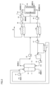
- FIG. 1 is a schematic diagram showing an example of a water treatment system according to Embodiment 1.
- FIG. FIG. 2 is a schematic diagram showing an example of a water treatment system according to Embodiment 2;
- FIG. 10 is a schematic diagram showing an example of a water treatment system according to Embodiment 3;
- FIG. 10 is a schematic diagram showing another example of the water treatment system according to Embodiment 3;
- the water treatment method of the present invention is a method for separating water from a feed solution (liquid containing water and components other than water).
- Feed solutions include, for example, seawater, river water, lake water, industrial wastewater, and the like.
- the water treatment method of the present invention includes at least a forward osmosis process, a phase separation process, and a membrane separation process, which will be described below.
- forward osmosis process In the forward osmosis process, one side of the forward osmosis membrane is contacted with a feed solution containing water and non-water components, while the other side of the forward osmosis membrane is exposed to a draw solute whose solubility decreases with increasing temperature. contact with solution. This causes the water contained in the feed solution to move through the forward osmosis membrane into the draw solution.
- the forward osmosis membrane is not particularly limited, and various membranes that can be used for forward osmosis can be used.
- semipermeable membranes examples include reverse osmosis membranes (RO membranes), forward osmosis membranes (FO membranes), nanofiltration membranes (NF membranes), ultrafiltration membranes (UF membranes), : Ultrafiltration Membrane).
- the semipermeable membrane is preferably a reverse osmosis membrane, a forward osmosis membrane, or a nanofiltration membrane.
- the pressure of the feed solution in the first chamber is preferably 0.01 to 10 MPa.
- the pore size of RO membranes and FO membranes is about 2 nm or less, and the pore size of UF membranes is about 2 to 100 nm.
- the NF membrane has a relatively low rejection rate of ions and salts, and the pore size of the NF membrane is usually about 1 to 2 nm.
- the salt removal rate of the RO membrane, FO membrane, or NF membrane is preferably 90% or more.
- the material constituting the semipermeable membrane is not particularly limited, but examples thereof include cellulose-based resins, polysulfone-based resins, and polyamide-based resins.
- the semipermeable membrane is preferably made of a material containing at least one of cellulose resin and polysulfone resin.
- the cellulose resin is preferably cellulose acetate resin.
- Cellulose acetate-based resins are resistant to chlorine, which is a disinfectant, and have the characteristic of being able to suppress the growth of microorganisms.
- the cellulose acetate-based resin is preferably cellulose acetate, and more preferably cellulose triacetate from the viewpoint of durability.
- Examples of the cellulose-based semipermeable membrane include CTA (manufactured by Toyobo Co., Ltd.).
- the polysulfone-based resin is preferably a polyethersulfone-based resin.
- the polyethersulfone-based resin is preferably sulfonated polyethersulfone.
- the shape of the semipermeable membrane is not particularly limited, but examples thereof include a flat membrane, a spiral membrane and a hollow fiber membrane.
- Hollow fiber membranes (hollow fiber type semipermeable membranes) have smaller membrane thickness than spiral type semipermeable membranes, etc., and can increase the membrane area per module, which can increase the permeation efficiency.
- the draw solute used in the present invention is not particularly limited as long as it is a substance whose solubility decreases with increasing temperature. It should be noted that such a decrease in solubility is reversible, and conversely, if the temperature decreases, it is preferable that the solubility increases.
- Such draw solutes include, for example, LCST (lower critical solution temperature) type phase transition materials.
- LCST lower critical solution temperature
- an aqueous solution containing an LCST-type phase transition material undergoes dehydration of the solute as the temperature of the solution rises, and temperature phase transition (liquid-liquid phase separation) occurs due to aggregation of the solute molecules.
- temperature phase transition liquid-liquid phase separation
- polymolecular associations are formed even in the temperature range below the phase transition temperature (homogeneous phase region below the LCST curve)
- the osmotic pressure of the solution increases due to the temperature rise. is expected to decrease.
- LCST-type phase transition materials include LCST-type temperature-responsive polymers.
- the LCST-type temperature-responsive polymer dissolves in water at relatively low temperatures, and when the temperature rises above a predetermined temperature (specific lower critical solution temperature: LCST), a dilute phase (low-concentration draw solution) and a dense phase (high concentration draw solution) and phase separation.
- LCST specific lower critical solution temperature
- a dilute phase low-concentration draw solution
- dense phase high concentration draw solution
- the LCST-type thermoresponsive polymer preferably has at least one hydrophilic group in at least some or all structural units (monomer units). Moreover, the temperature-responsive polymer may have a hydrophobic group in some structural units while having a hydrophilic group. In order for the temperature-responsive polymer to have temperature-responsiveness, it is considered that the balance between the hydrophilic groups and the hydrophobic groups contained in the molecule is important.
- hydrophilic groups include hydroxyl groups, carboxyl groups, acetyl groups, aldehyde groups, ether bonds, and ester bonds.
- temperature-responsive polymers include polyvinyl ether-based polymers, polyvinyl acetate-based polymers, and (meth)acrylic acid-based polymers.
- Polyvinyl ether-based polymers include polymethyl vinyl ether, vinyl ether having an oxyethylene chain, and polyhydroxybutyl vinyl ether.
- LCST-type temperature-responsive polymer products examples include Pluronic (registered trademark) (manufactured by BASF), which is a block copolymer of polyoxypropylene and polyoxyethylene.
- LCST-type phase transition materials other than LCST-type temperature-responsive polymers include LCST-type ionic liquids, glycol ether-based LCST-type phase-change materials, acid amide-based LCST-type phase-change materials, and amine-based LCST-type phase transition materials.
- a phase transition material etc. are mentioned.
- Patent Document 2 International Publication No. 2018/150690
- thermo-responsive draw solution changes with temperature (e.g., decreases with temperature rise).
- the osmotic pressure of the draw solution (after raising the temperature) to be subjected to the membrane separation step is preferably 0.01 to 2 MPa, more preferably 0.01 to 1 MPa.
- a feed solution (FS) is allowed to flow into a first chamber 11 provided in contact with one surface of a forward osmosis membrane 10, and the FS is passed through the forward osmosis membrane. 10 is brought into contact with one side.
- a draw solution (DS) containing a draw solute is allowed to flow into the second chamber 12 provided in contact with the other surface of the forward osmosis membrane 10, and the DS is brought into contact with the other surface of the forward osmosis membrane 10.
- the temperature of the forward osmosis step (the temperature of the FS solution at the inlet of the first chamber 11 and the temperature of the DS at the inlet in the second chamber 12) is preferably less than 40°C, more preferably 20-35 °C.
- Phase separation step In the phase separation step, after the forward osmosis step, the temperature of the draw solution is increased to separate the draw solution into a low-concentration draw solution (low-concentration DS) and a high-concentration draw solution (high-concentration DS) (phase separation). do.
- low-concentration draw solution low-concentration draw solution
- high-concentration draw solution high-concentration draw solution
- the temperature of the draw solution after rising in the phase separation step is preferably 40°C or higher and 95°C or lower, more preferably 40°C or higher and 90°C or lower, and still more preferably 40°C or higher and 85°C or lower.
- the draw solution containing water in the feed solution is flowed into the separation tank 3, where the temperature of the draw solution is raised to separate it into a dilute phase (low-concentration draw solution) and a rich phase (high-concentration draw solution).
- the temperature of the draw solution is raised above the LCST to separate the dilute phase (low-concentration DS) and the rich phase (high-concentration DS). can be done.
- the separation tank 3 preferably has a heating mechanism.
- a heating mechanism such as a heat exchanger may be provided upstream of the separation tank 3 in order to raise the temperature of the draw solution.
- a separation membrane In the membrane separation process, a separation membrane is used to separate a low-concentration draw solution (low-concentration DS) into water and a concentrate containing a draw solute using a pressure difference due to pressurization, decompression, or the like as a driving force.
- a separation membrane for example, a UF membrane, an NF membrane, an RO membrane, or the like can be used.
- the temperature of the membrane separation process is preferably higher than the temperature of the forward osmosis process. Also, a temperature lower than the phase separation temperature is preferred.
- the temperature in the membrane separation step is more preferably 40°C or higher and 95°C or lower, still more preferably 40°C or higher and 90°C or lower, and even more preferably 40°C or higher and 85°C or lower.
- At least one of the high-concentration DS containing a large amount of draw solute generated in the phase separation step and the concentrate (concentrated low-concentration DS) containing the draw solute generated in the membrane separation step is used for forward osmosis. Recycled as draw solution. At least a portion of the highly concentrated draw solution and/or the concentrated solution that is recycled in this manner is referred to herein as a "regenerated draw solution.”
- the regenerated draw solution (regenerated DS) is reused as the draw solution after being cooled by heat exchange with the cooling liquid.
- the regenerated DS has a high temperature due to the temperature rise in the phase separation process, but it must be cooled below the heat-resistant temperature of the FO module 1 used in the forward osmosis process, for example.
- the DS is regenerated to a temperature at which a sufficient osmotic pressure can be obtained before reuse. Must be cooled.
- the cooling liquid used for cooling (heat exchange) of the regenerated DS.
- the cooling liquid is preferably a liquid that has a higher cooling efficiency (lower temperature) than the dilute draw solution and the concentrated feed solution. In this case, the cooling efficiency of the regenerated DS is improved as compared with the conventional one, and the regenerated DS can be sufficiently cooled before reuse.
- At least seawater is preferably used as the cooling liquid (liquid other than the diluted draw solution and the concentrated feed solution).
- Seawater is typically cooler than the dilute draw solution and the concentrated feed solution, and therefore has a higher cooling efficiency than the dilute draw solution and the concentrated feed solution.
- the seawater that has been used to cool the regenerated DS in the heat exchanger 7 may be discharged to the ocean or the like, but may be supplied to the first chamber 11 of the FO module 1 as shown in FIG. preferable.
- the seawater used to cool the regenerated DS has a higher temperature than the original seawater, but this increases the osmotic pressure and decreases the viscosity, resulting in an overall increase in the amount of permeated water. This is because the effect of
- FIG. 1 is a schematic diagram showing an example of a water treatment system according to Embodiment 1.
- FIG. 1 is a schematic diagram showing an example of a water treatment system according to Embodiment 1.
- the water treatment system of this embodiment used in the above water treatment method includes: A forward osmosis membrane 10, a first chamber 11 provided for contacting one side of the forward osmosis membrane 10 with a feed solution, and a first chamber 11 provided for contacting the other side of the forward osmosis membrane with a draw solution.
- a forward osmosis module 1 comprising two chambers 12; a separation tank 3 having a heating mechanism for separating the draw solution into a low-concentration draw solution and a high-concentration draw solution by increasing the temperature of the draw solution; a separation membrane 20 (separation membrane module 2) for separating a low-concentration draw solution into water and a draw solute; a heat exchanger 7 for cooling the regenerated draw solution.
- pumps 41 to 46 cause FS, DS, water, etc. to flow in the directions of the arrows.
- the pump 45 is normally a high-pressure pump.
- the separation tank 3 has a heating mechanism. That is, hot water such as waste heat water is supplied around the separation tank 3 in order to raise the temperature of the diluted DS supplied to the separation tank 3 and cause phase separation. Thus, in the phase separation process performed in the separation tank 3, heat energy is required to raise the temperature of the draw solution. It is possible to suppress the increase in cost due to The temperature of the hot water may be adjusted according to the target value of the temperature after the DS rise in the phase separation step.
- the draw solution (diluted DS) undergoes phase separation into low-concentration DS and high-concentration DS due to the temperature rise.
- the high-concentration DS separated in the separation tank 3 and the low-concentration DS (concentrate) concentrated in the separation membrane module 2 are sent to the tank 5 by, for example, a pump 44 and temporarily stored. After that, it is reused as a DS for the forward osmosis process.
- the embodiment is not limited to that shown in FIG. 1, and either the high-concentration DS or the concentrated liquid may be reused as the DS in the forward osmosis process. Also, at least one of the high-concentration DS and the concentrated liquid may be reused entirely or partly. That is, at least a portion of at least one of the high-concentration DS and the concentrated liquid is reused as the DS in the forward osmosis process.
- the temporary storage in the tank 5 shown in FIG. may be connected by
- the regenerated DS (at least a portion of the concentrated draw solution and/or the concentrate) is fed to the forward osmosis module 1 in the heat exchanger 7 before being supplied to the FS (e.g. After being cooled by heat exchange with sea water, it is reused as a DS draw solution.
- the FS (for example, seawater) may be used entirely or only partially for cooling the regenerated DS.
- the separation membrane 20 for separating the low-concentration draw solution into water and the draw solute
- UF membrane Ultrafiltration Membrane
- NF membrane Nanofiltration Membrane
- RO membrane Reverse Osmosis Membrane
- the separation membrane module preferably has heat resistance at high temperatures (eg, 40°C or higher). This is to enable the membrane separation process to be performed on the high-temperature, low-concentration DS discharged from the separation tank 3 .
- the amount of concentrated FS used as the cooling liquid may exceed the amount of FS (for example, seawater) simultaneously used as the cooling liquid.
- heat-resistant separation membrane materials include polyethersulfone (PES)-based resins, polyamide (PA)-based resins, and polyvinyl alcohol (PVA)-based resins.
- PES polyethersulfone
- PA polyamide
- PVA polyvinyl alcohol
- parts other than the separation membrane also have heat resistance, and it is preferable that the separation membrane module has heat resistance as a whole.
- heat-resistant separation membrane module products include Thermoplus (manufactured by Nitto Denko Corporation), Durathermo (manufactured by GE Water Technologies), Romembra (registered trademark) TS series (manufactured by Toray Industries, Inc.), and the like. mentioned.
- heat-resistant separation membranes include, for example, ceramics such as alumina and silica.
- silica for heat-resistant membranes include silica derived from bistriylethoxysilylethane (Noryo Tsuru, "Development of Robust RO/NF Membrane Compatible with Various Water Sources", Journal of Japan Society of Water Environment, vol. 36(A), No.1, pp.8-10, 2013).
- FIG. 2 is a schematic diagram showing an example of a water treatment system according to Embodiment 2.
- the water treatment system shown in FIG. 2 further includes a heat exchanger 8 in addition to the water treatment system of Embodiment 1 shown in FIG. As shown in FIG. 2, the heat exchanger 8 uses concentrated FS as the cooling liquid.
- FIG. 3 is a schematic diagram showing an example of a water treatment system according to Embodiment 3.
- the water treatment system of Embodiment 3 shown in FIG. 3 further includes heat exchangers 61 and 62 in addition to the water treatment system of Embodiment 1 shown in FIG. As shown in FIG. 3, the heat exchangers 61 and 62 use diluted DS as the cooling liquid.
- the temperature of the finally obtained water is reduced by cooling the water with the heat exchanger 61. can be lowered to the desired temperature.
- the waste heat of the regenerated DS (low-concentration DS and high-concentration DS) discharged from the separation tank 3 is used to dilute the diluted DS supplied to the separation tank 3 through heat exchange in the heat exchangers 61 and 62. Since it can be heated, the thermal energy required for the phase separation process can be reduced, and the energy efficiency of water treatment can be increased.
- the separation membrane module 2 (separation membrane 20) is arranged upstream of the heat exchanger 61.
- the high-temperature low-concentration DS discharged from the separation tank 3 is subjected to the membrane separation process.
- the membrane separation process is carried out for such a high-temperature DS, the water permeation efficiency is high, so the pressure of the pump required for the membrane separation process is low, so the energy required for the pump is reduced, and the energy for water treatment An effect of improving efficiency is expected.
- the separation membrane module 2 (separation membrane 20) must have heat resistance at high temperatures (for example, 40° C. or higher).
- the separation membrane module 2 may be provided downstream of the heat exchanger 61, as shown in FIG. In this case, in the separation membrane module 2 , the membrane separation process is performed on the low-concentration DS after the temperature has been lowered by the heat exchanger 61 . Therefore, in the water treatment system shown in FIG. 4, it is possible to use, as the separation membrane module 2, a separation membrane module that does not have heat resistance at high temperatures (for example, 40° C. or higher) used for water treatment at room temperature. can.
- high temperatures for example, 40° C. or higher
- 1 forward osmosis module 10 forward osmosis membrane, 11 first chamber, 12 second chamber, 2 separation membrane module, 20 separation membrane, 3 separation tank, 41 to 47 pump, 5 tank, 61, 62, 7, 8 heat exchange vessel.
Landscapes
- Engineering & Computer Science (AREA)
- Water Supply & Treatment (AREA)
- Chemical & Material Sciences (AREA)
- Life Sciences & Earth Sciences (AREA)
- Hydrology & Water Resources (AREA)
- Environmental & Geological Engineering (AREA)
- Organic Chemistry (AREA)
- Chemical Kinetics & Catalysis (AREA)
- Separation Using Semi-Permeable Membranes (AREA)
Priority Applications (1)
| Application Number | Priority Date | Filing Date | Title |
|---|---|---|---|
| JP2023552863A JPWO2023058592A1 (https=) | 2021-10-07 | 2022-10-03 |
Applications Claiming Priority (2)
| Application Number | Priority Date | Filing Date | Title |
|---|---|---|---|
| JP2021-165631 | 2021-10-07 | ||
| JP2021165631 | 2021-10-07 |
Publications (1)
| Publication Number | Publication Date |
|---|---|
| WO2023058592A1 true WO2023058592A1 (ja) | 2023-04-13 |
Family
ID=85804252
Family Applications (1)
| Application Number | Title | Priority Date | Filing Date |
|---|---|---|---|
| PCT/JP2022/036916 Ceased WO2023058592A1 (ja) | 2021-10-07 | 2022-10-03 | 水処理方法および水処理システム |
Country Status (2)
| Country | Link |
|---|---|
| JP (1) | JPWO2023058592A1 (https=) |
| WO (1) | WO2023058592A1 (https=) |
Cited By (1)
| Publication number | Priority date | Publication date | Assignee | Title |
|---|---|---|---|---|
| US20260015275A1 (en) * | 2023-08-28 | 2026-01-15 | Bob Cantrell | Thermal driven water desalination system using forward osmosis |
Citations (5)
| Publication number | Priority date | Publication date | Assignee | Title |
|---|---|---|---|---|
| JP2016041411A (ja) * | 2014-08-19 | 2016-03-31 | Jfeエンジニアリング株式会社 | 水の脱塩処理方法および装置 |
| JP2016041412A (ja) * | 2014-08-19 | 2016-03-31 | Jfeエンジニアリング株式会社 | 水の脱塩処理方法および装置 |
| WO2018150690A1 (ja) * | 2017-02-17 | 2018-08-23 | 国立大学法人神戸大学 | 水処理方法および水処理システム |
| WO2019004281A1 (ja) * | 2017-06-27 | 2019-01-03 | Jfeエンジニアリング株式会社 | 水処理装置および水処理方法 |
| JP2019141812A (ja) * | 2018-02-23 | 2019-08-29 | Jfeエンジニアリング株式会社 | 水処理装置および水処理方法 |
-
2022
- 2022-10-03 WO PCT/JP2022/036916 patent/WO2023058592A1/ja not_active Ceased
- 2022-10-03 JP JP2023552863A patent/JPWO2023058592A1/ja active Pending
Patent Citations (5)
| Publication number | Priority date | Publication date | Assignee | Title |
|---|---|---|---|---|
| JP2016041411A (ja) * | 2014-08-19 | 2016-03-31 | Jfeエンジニアリング株式会社 | 水の脱塩処理方法および装置 |
| JP2016041412A (ja) * | 2014-08-19 | 2016-03-31 | Jfeエンジニアリング株式会社 | 水の脱塩処理方法および装置 |
| WO2018150690A1 (ja) * | 2017-02-17 | 2018-08-23 | 国立大学法人神戸大学 | 水処理方法および水処理システム |
| WO2019004281A1 (ja) * | 2017-06-27 | 2019-01-03 | Jfeエンジニアリング株式会社 | 水処理装置および水処理方法 |
| JP2019141812A (ja) * | 2018-02-23 | 2019-08-29 | Jfeエンジニアリング株式会社 | 水処理装置および水処理方法 |
Cited By (1)
| Publication number | Priority date | Publication date | Assignee | Title |
|---|---|---|---|---|
| US20260015275A1 (en) * | 2023-08-28 | 2026-01-15 | Bob Cantrell | Thermal driven water desalination system using forward osmosis |
Also Published As
| Publication number | Publication date |
|---|---|
| JPWO2023058592A1 (https=) | 2023-04-13 |
Similar Documents
| Publication | Publication Date | Title |
|---|---|---|
| JP7117718B2 (ja) | 水処理方法および水処理システム | |
| Wang et al. | Integrated forward osmosis–membrane distillation (FO–MD) hybrid system for the concentration of protein solutions | |
| CN102325581A (zh) | 用于正向渗透液净化的系统及方法 | |
| JP2019141812A (ja) | 水処理装置および水処理方法 | |
| WO2013118859A1 (ja) | 中空糸型半透膜及びその製造方法及びモジュール及び水処理方法 | |
| CN108654385A (zh) | 一种兼具高选择性高渗透性超滤膜的制备方法 | |
| JP2018001111A (ja) | 塩水の淡水化処理方法、および、塩水の淡水化処理システム | |
| JP6028645B2 (ja) | 水処理装置 | |
| WO2023058592A1 (ja) | 水処理方法および水処理システム | |
| CN117529361A (zh) | 膜分离方法和疏松ro膜的制造方法 | |
| JP7815741B2 (ja) | 水処理方法および水処理システム | |
| JP2012017325A (ja) | フルフラールの製造方法およびその装置 | |
| WO2019004281A1 (ja) | 水処理装置および水処理方法 | |
| JP6414528B2 (ja) | 水の脱塩処理方法および装置 | |
| KR20170089230A (ko) | 유도용액을 이용한 역삼투법 및 나노여과법을 이용한 해수담수화 방법 | |
| JP6210034B2 (ja) | 水の脱塩処理方法および装置 | |
| JP6210008B2 (ja) | 水処理装置 | |
| JPS59156402A (ja) | 逆浸透膜による有機物の濃縮方法 | |
| JP7756462B2 (ja) | 正浸透膜及びその製造方法 | |
| JP2021159874A (ja) | 正浸透水処理方法および装置 | |
| JP2022129708A (ja) | 正浸透水処理装置および方法 | |
| JPWO2023058592A5 (https=) | ||
| JP2024005365A (ja) | 水処理方法および水処理システム | |
| JP6879228B2 (ja) | 水処理装置および水処理方法 | |
| CN102172481B (zh) | 一种复合结构分离膜的制备方法 |
Legal Events
| Date | Code | Title | Description |
|---|---|---|---|
| 121 | Ep: the epo has been informed by wipo that ep was designated in this application |
Ref document number: 22878461 Country of ref document: EP Kind code of ref document: A1 |
|
| WWE | Wipo information: entry into national phase |
Ref document number: 2023552863 Country of ref document: JP |
|
| NENP | Non-entry into the national phase |
Ref country code: DE |
|
| 122 | Ep: pct application non-entry in european phase |
Ref document number: 22878461 Country of ref document: EP Kind code of ref document: A1 |