WO2023054648A1 - Procédé de fonctionnement d'un module de membrane à fibres creuses - Google Patents
Procédé de fonctionnement d'un module de membrane à fibres creuses Download PDFInfo
- Publication number
- WO2023054648A1 WO2023054648A1 PCT/JP2022/036600 JP2022036600W WO2023054648A1 WO 2023054648 A1 WO2023054648 A1 WO 2023054648A1 JP 2022036600 W JP2022036600 W JP 2022036600W WO 2023054648 A1 WO2023054648 A1 WO 2023054648A1
- Authority
- WO
- WIPO (PCT)
- Prior art keywords
- hollow fiber
- fiber membrane
- filtrate
- filtration
- solution
- Prior art date
Links
- 239000012528 membrane Substances 0.000 title claims abstract description 386
- 239000012510 hollow fiber Substances 0.000 title claims abstract description 293
- 238000000034 method Methods 0.000 title claims description 101
- 239000000706 filtrate Substances 0.000 claims abstract description 157
- 239000007788 liquid Substances 0.000 claims abstract description 92
- 238000009295 crossflow filtration Methods 0.000 claims abstract description 31
- 239000000243 solution Substances 0.000 claims description 151
- 239000011550 stock solution Substances 0.000 claims description 88
- 238000001914 filtration Methods 0.000 claims description 84
- 239000011148 porous material Substances 0.000 claims description 63
- 238000011001 backwashing Methods 0.000 claims description 17
- 238000004140 cleaning Methods 0.000 claims description 17
- OKTJSMMVPCPJKN-UHFFFAOYSA-N Carbon Chemical compound [C] OKTJSMMVPCPJKN-UHFFFAOYSA-N 0.000 claims description 8
- 229910052799 carbon Inorganic materials 0.000 claims description 8
- 238000011049 filling Methods 0.000 claims description 8
- 238000000108 ultra-filtration Methods 0.000 claims description 8
- 238000011017 operating method Methods 0.000 abstract description 3
- 238000004382 potting Methods 0.000 description 61
- 239000010410 layer Substances 0.000 description 46
- XLYOFNOQVPJJNP-UHFFFAOYSA-N water Substances O XLYOFNOQVPJJNP-UHFFFAOYSA-N 0.000 description 43
- 229920000642 polymer Polymers 0.000 description 39
- 239000002904 solvent Substances 0.000 description 37
- 239000012141 concentrate Substances 0.000 description 22
- 239000000853 adhesive Substances 0.000 description 21
- 230000001070 adhesive effect Effects 0.000 description 21
- 230000035699 permeability Effects 0.000 description 20
- 230000004907 flux Effects 0.000 description 18
- 229920005989 resin Polymers 0.000 description 18
- 239000011347 resin Substances 0.000 description 18
- 238000000926 separation method Methods 0.000 description 17
- 230000000694 effects Effects 0.000 description 16
- 239000003795 chemical substances by application Substances 0.000 description 14
- 238000009826 distribution Methods 0.000 description 14
- 238000004519 manufacturing process Methods 0.000 description 14
- 238000004088 simulation Methods 0.000 description 14
- 238000012360 testing method Methods 0.000 description 13
- 238000005191 phase separation Methods 0.000 description 11
- 108010010803 Gelatin Proteins 0.000 description 10
- 229920000159 gelatin Polymers 0.000 description 10
- 239000008273 gelatin Substances 0.000 description 10
- 235000019322 gelatine Nutrition 0.000 description 10
- 235000011852 gelatine desserts Nutrition 0.000 description 10
- -1 heat resistance Substances 0.000 description 9
- 230000001965 increasing effect Effects 0.000 description 9
- 229920001223 polyethylene glycol Polymers 0.000 description 9
- YEJRWHAVMIAJKC-UHFFFAOYSA-N 4-Butyrolactone Chemical compound O=C1CCCO1 YEJRWHAVMIAJKC-UHFFFAOYSA-N 0.000 description 8
- 239000002202 Polyethylene glycol Substances 0.000 description 8
- 239000002131 composite material Substances 0.000 description 8
- 238000005259 measurement Methods 0.000 description 8
- LYCAIKOWRPUZTN-UHFFFAOYSA-N Ethylene glycol Chemical compound OCCO LYCAIKOWRPUZTN-UHFFFAOYSA-N 0.000 description 7
- 239000007864 aqueous solution Substances 0.000 description 7
- 230000005540 biological transmission Effects 0.000 description 7
- 238000001816 cooling Methods 0.000 description 7
- 238000010586 diagram Methods 0.000 description 7
- 238000005374 membrane filtration Methods 0.000 description 7
- 238000007789 sealing Methods 0.000 description 7
- 239000000126 substance Substances 0.000 description 7
- 230000008719 thickening Effects 0.000 description 7
- 238000005406 washing Methods 0.000 description 7
- ZWEHNKRNPOVVGH-UHFFFAOYSA-N 2-Butanone Chemical compound CCC(C)=O ZWEHNKRNPOVVGH-UHFFFAOYSA-N 0.000 description 6
- 238000012935 Averaging Methods 0.000 description 6
- UHOVQNZJYSORNB-UHFFFAOYSA-N Benzene Chemical compound C1=CC=CC=C1 UHOVQNZJYSORNB-UHFFFAOYSA-N 0.000 description 6
- LFQSCWFLJHTTHZ-UHFFFAOYSA-N Ethanol Chemical compound CCO LFQSCWFLJHTTHZ-UHFFFAOYSA-N 0.000 description 6
- OKKJLVBELUTLKV-UHFFFAOYSA-N Methanol Chemical compound OC OKKJLVBELUTLKV-UHFFFAOYSA-N 0.000 description 6
- SECXISVLQFMRJM-UHFFFAOYSA-N N-Methylpyrrolidone Chemical compound CN1CCCC1=O SECXISVLQFMRJM-UHFFFAOYSA-N 0.000 description 6
- YXFVVABEGXRONW-UHFFFAOYSA-N Toluene Chemical compound CC1=CC=CC=C1 YXFVVABEGXRONW-UHFFFAOYSA-N 0.000 description 6
- MTHSVFCYNBDYFN-UHFFFAOYSA-N diethylene glycol Chemical compound OCCOCCO MTHSVFCYNBDYFN-UHFFFAOYSA-N 0.000 description 6
- VLKZOEOYAKHREP-UHFFFAOYSA-N n-Hexane Chemical compound CCCCCC VLKZOEOYAKHREP-UHFFFAOYSA-N 0.000 description 6
- 238000002145 thermally induced phase separation Methods 0.000 description 6
- CSCPPACGZOOCGX-UHFFFAOYSA-N Acetone Chemical compound CC(C)=O CSCPPACGZOOCGX-UHFFFAOYSA-N 0.000 description 5
- 239000002033 PVDF binder Substances 0.000 description 5
- 238000004364 calculation method Methods 0.000 description 5
- 229920001577 copolymer Polymers 0.000 description 5
- 239000000835 fiber Substances 0.000 description 5
- 239000012046 mixed solvent Substances 0.000 description 5
- 229920002981 polyvinylidene fluoride Polymers 0.000 description 5
- BQCIDUSAKPWEOX-UHFFFAOYSA-N 1,1-Difluoroethene Chemical compound FC(F)=C BQCIDUSAKPWEOX-UHFFFAOYSA-N 0.000 description 4
- RFFLAFLAYFXFSW-UHFFFAOYSA-N 1,2-dichlorobenzene Chemical compound ClC1=CC=CC=C1Cl RFFLAFLAYFXFSW-UHFFFAOYSA-N 0.000 description 4
- YCKRFDGAMUMZLT-UHFFFAOYSA-N Fluorine atom Chemical compound [F] YCKRFDGAMUMZLT-UHFFFAOYSA-N 0.000 description 4
- OFBQJSOFQDEBGM-UHFFFAOYSA-N Pentane Chemical compound CCCCC OFBQJSOFQDEBGM-UHFFFAOYSA-N 0.000 description 4
- WYURNTSHIVDZCO-UHFFFAOYSA-N Tetrahydrofuran Chemical compound C1CCOC1 WYURNTSHIVDZCO-UHFFFAOYSA-N 0.000 description 4
- 238000009825 accumulation Methods 0.000 description 4
- 230000008859 change Effects 0.000 description 4
- 239000012153 distilled water Substances 0.000 description 4
- 229910052731 fluorine Inorganic materials 0.000 description 4
- 239000011737 fluorine Substances 0.000 description 4
- 229920001519 homopolymer Polymers 0.000 description 4
- 239000002245 particle Substances 0.000 description 4
- 239000002994 raw material Substances 0.000 description 4
- 150000005846 sugar alcohols Polymers 0.000 description 4
- VZGDMQKNWNREIO-UHFFFAOYSA-N tetrachloromethane Chemical compound ClC(Cl)(Cl)Cl VZGDMQKNWNREIO-UHFFFAOYSA-N 0.000 description 4
- ZMXDDKWLCZADIW-UHFFFAOYSA-N N,N-Dimethylformamide Chemical compound CN(C)C=O ZMXDDKWLCZADIW-UHFFFAOYSA-N 0.000 description 3
- WHNWPMSKXPGLAX-UHFFFAOYSA-N N-Vinyl-2-pyrrolidone Chemical compound C=CN1CCCC1=O WHNWPMSKXPGLAX-UHFFFAOYSA-N 0.000 description 3
- DNIAPMSPPWPWGF-UHFFFAOYSA-N Propylene glycol Chemical compound CC(O)CO DNIAPMSPPWPWGF-UHFFFAOYSA-N 0.000 description 3
- 235000013361 beverage Nutrition 0.000 description 3
- 229920002301 cellulose acetate Polymers 0.000 description 3
- 238000005345 coagulation Methods 0.000 description 3
- 230000015271 coagulation Effects 0.000 description 3
- 238000002425 crystallisation Methods 0.000 description 3
- 230000008025 crystallization Effects 0.000 description 3
- 238000005516 engineering process Methods 0.000 description 3
- 238000000855 fermentation Methods 0.000 description 3
- 230000004151 fermentation Effects 0.000 description 3
- 235000013305 food Nutrition 0.000 description 3
- 239000002346 layers by function Substances 0.000 description 3
- 239000007791 liquid phase Substances 0.000 description 3
- 238000001471 micro-filtration Methods 0.000 description 3
- 238000000465 moulding Methods 0.000 description 3
- 239000012466 permeate Substances 0.000 description 3
- 239000012071 phase Substances 0.000 description 3
- 230000008569 process Effects 0.000 description 3
- 230000000717 retained effect Effects 0.000 description 3
- 238000001223 reverse osmosis Methods 0.000 description 3
- FFWSICBKRCICMR-UHFFFAOYSA-N 5-methyl-2-hexanone Chemical compound CC(C)CCC(C)=O FFWSICBKRCICMR-UHFFFAOYSA-N 0.000 description 2
- VTYYLEPIZMXCLO-UHFFFAOYSA-L Calcium carbonate Chemical compound [Ca+2].[O-]C([O-])=O VTYYLEPIZMXCLO-UHFFFAOYSA-L 0.000 description 2
- IAZDPXIOMUYVGZ-UHFFFAOYSA-N Dimethylsulphoxide Chemical compound CS(C)=O IAZDPXIOMUYVGZ-UHFFFAOYSA-N 0.000 description 2
- PEDCQBHIVMGVHV-UHFFFAOYSA-N Glycerine Chemical compound OCC(O)CO PEDCQBHIVMGVHV-UHFFFAOYSA-N 0.000 description 2
- 239000004372 Polyvinyl alcohol Substances 0.000 description 2
- 240000004808 Saccharomyces cerevisiae Species 0.000 description 2
- VYPSYNLAJGMNEJ-UHFFFAOYSA-N Silicium dioxide Chemical compound O=[Si]=O VYPSYNLAJGMNEJ-UHFFFAOYSA-N 0.000 description 2
- 235000010724 Wisteria floribunda Nutrition 0.000 description 2
- 230000009471 action Effects 0.000 description 2
- 125000001931 aliphatic group Chemical group 0.000 description 2
- 150000001338 aliphatic hydrocarbons Chemical class 0.000 description 2
- XXROGKLTLUQVRX-UHFFFAOYSA-N allyl alcohol Chemical compound OCC=C XXROGKLTLUQVRX-UHFFFAOYSA-N 0.000 description 2
- 150000004945 aromatic hydrocarbons Chemical class 0.000 description 2
- 125000003118 aryl group Chemical group 0.000 description 2
- 230000015572 biosynthetic process Effects 0.000 description 2
- PXKLMJQFEQBVLD-UHFFFAOYSA-N bisphenol F Chemical compound C1=CC(O)=CC=C1CC1=CC=C(O)C=C1 PXKLMJQFEQBVLD-UHFFFAOYSA-N 0.000 description 2
- 230000000903 blocking effect Effects 0.000 description 2
- 150000008280 chlorinated hydrocarbons Chemical class 0.000 description 2
- 230000000052 comparative effect Effects 0.000 description 2
- 238000012937 correction Methods 0.000 description 2
- 210000004748 cultured cell Anatomy 0.000 description 2
- 238000005520 cutting process Methods 0.000 description 2
- JHIVVAPYMSGYDF-UHFFFAOYSA-N cyclohexanone Chemical compound O=C1CCCCC1 JHIVVAPYMSGYDF-UHFFFAOYSA-N 0.000 description 2
- 238000007599 discharging Methods 0.000 description 2
- 239000003651 drinking water Substances 0.000 description 2
- 235000020188 drinking water Nutrition 0.000 description 2
- 230000002708 enhancing effect Effects 0.000 description 2
- 239000003822 epoxy resin Substances 0.000 description 2
- 229920000840 ethylene tetrafluoroethylene copolymer Polymers 0.000 description 2
- ACCCMOQWYVYDOT-UHFFFAOYSA-N hexane-1,1-diol Chemical compound CCCCCC(O)O ACCCMOQWYVYDOT-UHFFFAOYSA-N 0.000 description 2
- HJOVHMDZYOCNQW-UHFFFAOYSA-N isophorone Chemical compound CC1=CC(=O)CC(C)(C)C1 HJOVHMDZYOCNQW-UHFFFAOYSA-N 0.000 description 2
- 230000007774 longterm Effects 0.000 description 2
- 238000000691 measurement method Methods 0.000 description 2
- 230000007246 mechanism Effects 0.000 description 2
- 238000002844 melting Methods 0.000 description 2
- 230000008018 melting Effects 0.000 description 2
- 244000005700 microbiome Species 0.000 description 2
- 238000001728 nano-filtration Methods 0.000 description 2
- UWJJYHHHVWZFEP-UHFFFAOYSA-N pentane-1,1-diol Chemical compound CCCCC(O)O UWJJYHHHVWZFEP-UHFFFAOYSA-N 0.000 description 2
- 229920002492 poly(sulfone) Polymers 0.000 description 2
- 229920000647 polyepoxide Polymers 0.000 description 2
- 229920006393 polyether sulfone Polymers 0.000 description 2
- 229920002451 polyvinyl alcohol Polymers 0.000 description 2
- 238000000746 purification Methods 0.000 description 2
- 238000007790 scraping Methods 0.000 description 2
- 238000010008 shearing Methods 0.000 description 2
- 239000002356 single layer Substances 0.000 description 2
- YLQBMQCUIZJEEH-UHFFFAOYSA-N tetrahydrofuran Natural products C=1C=COC=1 YLQBMQCUIZJEEH-UHFFFAOYSA-N 0.000 description 2
- ZIBGPFATKBEMQZ-UHFFFAOYSA-N triethylene glycol Chemical compound OCCOCCOCCO ZIBGPFATKBEMQZ-UHFFFAOYSA-N 0.000 description 2
- 238000001291 vacuum drying Methods 0.000 description 2
- 238000012795 verification Methods 0.000 description 2
- 238000004065 wastewater treatment Methods 0.000 description 2
- 238000003466 welding Methods 0.000 description 2
- PUPZLCDOIYMWBV-UHFFFAOYSA-N (+/-)-1,3-Butanediol Chemical compound CC(O)CCO PUPZLCDOIYMWBV-UHFFFAOYSA-N 0.000 description 1
- AVQQQNCBBIEMEU-UHFFFAOYSA-N 1,1,3,3-tetramethylurea Chemical compound CN(C)C(=O)N(C)C AVQQQNCBBIEMEU-UHFFFAOYSA-N 0.000 description 1
- NLHHRLWOUZZQLW-UHFFFAOYSA-N Acrylonitrile Chemical compound C=CC#N NLHHRLWOUZZQLW-UHFFFAOYSA-N 0.000 description 1
- 101100165177 Caenorhabditis elegans bath-15 gene Proteins 0.000 description 1
- IMROMDMJAWUWLK-UHFFFAOYSA-N Ethenol Chemical compound OC=C IMROMDMJAWUWLK-UHFFFAOYSA-N 0.000 description 1
- CERQOIWHTDAKMF-UHFFFAOYSA-N Methacrylic acid Chemical compound CC(=C)C(O)=O CERQOIWHTDAKMF-UHFFFAOYSA-N 0.000 description 1
- FXHOOIRPVKKKFG-UHFFFAOYSA-N N,N-Dimethylacetamide Chemical compound CN(C)C(C)=O FXHOOIRPVKKKFG-UHFFFAOYSA-N 0.000 description 1
- 239000004696 Poly ether ether ketone Substances 0.000 description 1
- 239000004952 Polyamide Substances 0.000 description 1
- 239000004695 Polyether sulfone Substances 0.000 description 1
- 239000004642 Polyimide Substances 0.000 description 1
- 239000004721 Polyphenylene oxide Substances 0.000 description 1
- 239000004734 Polyphenylene sulfide Substances 0.000 description 1
- 239000004743 Polypropylene Substances 0.000 description 1
- XTXRWKRVRITETP-UHFFFAOYSA-N Vinyl acetate Chemical compound CC(=O)OC=C XTXRWKRVRITETP-UHFFFAOYSA-N 0.000 description 1
- 239000002253 acid Substances 0.000 description 1
- 239000000654 additive Substances 0.000 description 1
- 238000005273 aeration Methods 0.000 description 1
- 150000001336 alkenes Chemical class 0.000 description 1
- 150000001408 amides Chemical class 0.000 description 1
- 239000012298 atmosphere Substances 0.000 description 1
- 238000009835 boiling Methods 0.000 description 1
- WERYXYBDKMZEQL-UHFFFAOYSA-N butane-1,4-diol Chemical class OCCCCO WERYXYBDKMZEQL-UHFFFAOYSA-N 0.000 description 1
- 229910000019 calcium carbonate Inorganic materials 0.000 description 1
- 238000005266 casting Methods 0.000 description 1
- 239000001913 cellulose Substances 0.000 description 1
- 229920002678 cellulose Polymers 0.000 description 1
- 229920003174 cellulose-based polymer Polymers 0.000 description 1
- 238000005119 centrifugation Methods 0.000 description 1
- 238000003889 chemical engineering Methods 0.000 description 1
- 239000004927 clay Substances 0.000 description 1
- 229910052570 clay Inorganic materials 0.000 description 1
- 150000001875 compounds Chemical class 0.000 description 1
- 230000006866 deterioration Effects 0.000 description 1
- ZBCBWPMODOFKDW-UHFFFAOYSA-N diethanolamine Chemical compound OCCNCCO ZBCBWPMODOFKDW-UHFFFAOYSA-N 0.000 description 1
- 238000004090 dissolution Methods 0.000 description 1
- BXKDSDJJOVIHMX-UHFFFAOYSA-N edrophonium chloride Chemical compound [Cl-].CC[N+](C)(C)C1=CC=CC(O)=C1 BXKDSDJJOVIHMX-UHFFFAOYSA-N 0.000 description 1
- 229920001971 elastomer Polymers 0.000 description 1
- 150000002148 esters Chemical class 0.000 description 1
- 239000005038 ethylene vinyl acetate Substances 0.000 description 1
- 229920006244 ethylene-ethyl acrylate Polymers 0.000 description 1
- 238000002474 experimental method Methods 0.000 description 1
- 239000011521 glass Substances 0.000 description 1
- 235000011187 glycerol Nutrition 0.000 description 1
- 150000002334 glycols Chemical class 0.000 description 1
- 229920001477 hydrophilic polymer Polymers 0.000 description 1
- 238000002347 injection Methods 0.000 description 1
- 239000007924 injection Substances 0.000 description 1
- 229920000554 ionomer Polymers 0.000 description 1
- 239000000463 material Substances 0.000 description 1
- 239000002184 metal Substances 0.000 description 1
- 229910052751 metal Inorganic materials 0.000 description 1
- 239000010445 mica Substances 0.000 description 1
- 229910052618 mica group Inorganic materials 0.000 description 1
- 238000002156 mixing Methods 0.000 description 1
- 239000000203 mixture Substances 0.000 description 1
- 238000012986 modification Methods 0.000 description 1
- 230000004048 modification Effects 0.000 description 1
- JRZJOMJEPLMPRA-UHFFFAOYSA-N olefin Natural products CCCCCCCC=C JRZJOMJEPLMPRA-UHFFFAOYSA-N 0.000 description 1
- 238000013021 overheating Methods 0.000 description 1
- YWAKXRMUMFPDSH-UHFFFAOYSA-N pentene Chemical compound CCCC=C YWAKXRMUMFPDSH-UHFFFAOYSA-N 0.000 description 1
- 229920002493 poly(chlorotrifluoroethylene) Polymers 0.000 description 1
- 229920001200 poly(ethylene-vinyl acetate) Polymers 0.000 description 1
- 229920002647 polyamide Polymers 0.000 description 1
- 229920001230 polyarylate Polymers 0.000 description 1
- 229920000515 polycarbonate Polymers 0.000 description 1
- 239000004417 polycarbonate Substances 0.000 description 1
- 239000005023 polychlorotrifluoroethylene (PCTFE) polymer Substances 0.000 description 1
- 229920002530 polyetherether ketone Polymers 0.000 description 1
- 229920001601 polyetherimide Polymers 0.000 description 1
- 229920001721 polyimide Polymers 0.000 description 1
- 239000002861 polymer material Substances 0.000 description 1
- 238000006116 polymerization reaction Methods 0.000 description 1
- 229920006380 polyphenylene oxide Polymers 0.000 description 1
- 229920000069 polyphenylene sulfide Polymers 0.000 description 1
- 229920001155 polypropylene Polymers 0.000 description 1
- 229920001296 polysiloxane Polymers 0.000 description 1
- 229920001343 polytetrafluoroethylene Polymers 0.000 description 1
- 239000004810 polytetrafluoroethylene Substances 0.000 description 1
- 229920005749 polyurethane resin Polymers 0.000 description 1
- 239000004800 polyvinyl chloride Substances 0.000 description 1
- 229920000915 polyvinyl chloride Polymers 0.000 description 1
- 230000001737 promoting effect Effects 0.000 description 1
- QQONPFPTGQHPMA-UHFFFAOYSA-N propylene Natural products CC=C QQONPFPTGQHPMA-UHFFFAOYSA-N 0.000 description 1
- RUOJZAUFBMNUDX-UHFFFAOYSA-N propylene carbonate Chemical compound CC1COC(=O)O1 RUOJZAUFBMNUDX-UHFFFAOYSA-N 0.000 description 1
- 125000004805 propylene group Chemical group [H]C([H])([H])C([H])([*:1])C([H])([H])[*:2] 0.000 description 1
- 239000005060 rubber Substances 0.000 description 1
- 238000007127 saponification reaction Methods 0.000 description 1
- 238000001878 scanning electron micrograph Methods 0.000 description 1
- 239000000377 silicon dioxide Substances 0.000 description 1
- 239000013464 silicone adhesive Substances 0.000 description 1
- 229920002050 silicone resin Polymers 0.000 description 1
- 239000007787 solid Substances 0.000 description 1
- 239000007790 solid phase Substances 0.000 description 1
- 238000009987 spinning Methods 0.000 description 1
- 238000005507 spraying Methods 0.000 description 1
- 230000003068 static effect Effects 0.000 description 1
- 239000000454 talc Substances 0.000 description 1
- 229910052623 talc Inorganic materials 0.000 description 1
- WVLBCYQITXONBZ-UHFFFAOYSA-N trimethyl phosphate Chemical compound COP(=O)(OC)OC WVLBCYQITXONBZ-UHFFFAOYSA-N 0.000 description 1
- 239000002351 wastewater Substances 0.000 description 1
Images


Classifications
-
- B—PERFORMING OPERATIONS; TRANSPORTING
- B01—PHYSICAL OR CHEMICAL PROCESSES OR APPARATUS IN GENERAL
- B01D—SEPARATION
- B01D61/00—Processes of separation using semi-permeable membranes, e.g. dialysis, osmosis or ultrafiltration; Apparatus, accessories or auxiliary operations specially adapted therefor
- B01D61/14—Ultrafiltration; Microfiltration
- B01D61/22—Controlling or regulating
-
- B—PERFORMING OPERATIONS; TRANSPORTING
- B01—PHYSICAL OR CHEMICAL PROCESSES OR APPARATUS IN GENERAL
- B01D—SEPARATION
- B01D63/00—Apparatus in general for separation processes using semi-permeable membranes
- B01D63/02—Hollow fibre modules
-
- B—PERFORMING OPERATIONS; TRANSPORTING
- B01—PHYSICAL OR CHEMICAL PROCESSES OR APPARATUS IN GENERAL
- B01D—SEPARATION
- B01D69/00—Semi-permeable membranes for separation processes or apparatus characterised by their form, structure or properties; Manufacturing processes specially adapted therefor
- B01D69/08—Hollow fibre membranes
Definitions
- the present invention relates to a method for operating a hollow fiber membrane module for filtration.
- Membrane filtration using a separation membrane is used in the water treatment field such as drinking water production, water purification treatment, and wastewater treatment, and in recent years, it has been used in the fermentation field involving the cultivation of microorganisms and cultured cells, the pharmaceutical field, the food and beverage field, etc.
- the scope of application is expanding in various directions.
- membrane filtration using a hollow fiber membrane module is used in many fields due to the large amount of treated water, ease of washing, and the like.
- the cross-flow filtration operation is a method in which a raw liquid flow parallel to the surface of the hollow fiber membrane is always applied and part of the flow is filtered.
- Patent Documents 1 and 2 disclose a method of filtering a highly viscous liquid by internal pressure cross-flow filtration using an ultrafiltration membrane.
- the channel size of the concentrate solution is smaller than that of the external pressure type, so the channel blockage and pressure loss due to the flow of the concentrate solution may increase.
- the membrane area of the hollow fiber membrane module is reduced, and the filtration rate of the hollow fiber membrane module is reduced. Therefore, external pressure cross-flow filtration is often suitable for such undiluted solutions.
- Patent Document 3 discloses a method of applying external pressure cross-flow filtration to oil-water separation applications
- Patent Document 4 discloses a method of external pressure cross-flow filtration of a yeast culture solution.
- Patent Document 3 describes that it is preferable to widen the average dimension value between the hollow fiber membranes in order to suppress clogging of the flow path in the external pressure cross-flow filtration.
- transmembrane differential pressure increases.
- transmembrane differential pressure the difference between the differential pressure and the transmembrane differential pressure on the liquid outlet side.
- transmembrane differential pressure increases.
- Patent Document 1 discloses a method for maintaining a high level of filtration flow rate by returning backpressure washing wastewater to the stock solution in order to suppress clogging of the hollow fiber membrane due to an increase in the viscosity of the stock solution.
- Patent Document 2 discloses a method of controlling the Reynolds number during circulation filtration in order to suppress clogging of hollow fibers and obtain a large permeation flux.
- Patent Document 3 in the case of an external pressure circulation system, dirt on the membrane surface of the hollow fiber membrane can be stripped off by the flow of the liquid to be treated, and the content of water-insoluble oil and the concentration of suspended solids in the liquid to be treated can be reduced. It is described that filtration can be continued while suppressing fouling and clogging of the membrane surface even if it is high.
- Patent Document 4 describes that the use of high-strength hollow fiber membranes enables operation without breakage of the hollow fiber membranes when performing external pressure cross-flow filtration of a yeast culture solution.
- the present invention provides a hollow fiber membrane module that can reduce the transmembrane pressure difference, suppress the clogging speed, and reduce the cleaning frequency when there is a viscosity difference between the undiluted solution and the filtrate in external pressure cross-flow filtration.
- An object is to provide a driving method.
- the present invention provides the following method for operating a hollow fiber membrane module.
- a step of performing cross-flow filtration by supplying the stock solution to the outer surface side of the hollow fiber membrane, wherein the ratio of the viscosity ⁇ f of the stock solution to the viscosity ⁇ p of the filtrate is ⁇ f / ⁇ p ⁇ 1. 5, and the flow rate ratio of the flow rate v f of the undiluted solution to the flow rate v p of the filtrate is 0.02 ⁇ v p /v f ⁇ 0.3. how to drive.
- ⁇ 2> The method of operating a hollow fiber membrane module according to ⁇ 1>, wherein in the filtering step, the viscosity ⁇ f of the undiluted solution is 3.0 mPa ⁇ s or more.
- ⁇ 3> The hollow fiber membrane module according to ⁇ 1> or ⁇ 2>, wherein the dissolved organic carbon concentration of the undiluted solution in the filtering step is 1,000 mg/L or more and 100,000 mg/L or less. driving method.
- ⁇ 4> The method of operating a hollow fiber membrane module according to any one of ⁇ 1> to ⁇ 3>, wherein the hollow fiber membrane is an ultrafiltration membrane.
- ⁇ 5> The method of operating a hollow fiber membrane module according to any one of ⁇ 1> to ⁇ 4>, wherein the hollow fiber membrane has a breaking load of 500 gf/membrane or more.
- ⁇ 6> ⁇ 1> to ⁇ 5> wherein in the filtering step, the viscosity ⁇ f of the undiluted solution and the flow rate v f of the undiluted solution satisfy the relationship v f ⁇ 0.135 ⁇ f +3.0.
- ⁇ 7> The method of operating a hollow fiber membrane module according to any one of ⁇ 1> to ⁇ 6>, wherein the inner diameter D i of the hollow fiber membrane is 300 ⁇ m ⁇ D i ⁇ 1000 ⁇ m.
- ⁇ 8> The method of operating a hollow fiber membrane module according to any one of ⁇ 1> to ⁇ 7>, wherein the filling rate of the hollow fiber membrane module is 25% or more and 45% or less.
- ⁇ 9> The method of operating a hollow fiber membrane module according to any one of ⁇ 1> to ⁇ 8>, wherein the hollow fiber membrane has a membrane length of 0.50 m or more and 2.00 m or less.
- the method further includes a backwashing step in which a cleaning liquid is flowed from the inner surface of the hollow fiber membrane toward the outer surface thereof, and the pore diameter ⁇ o of the outer surface of the hollow fiber membrane is 0.005 ⁇ m ⁇ ⁇ 0 ⁇ 0.02 ⁇ m. Any one of ⁇ 1> to ⁇ 9>, wherein the ratio of the pore diameter ⁇ i on the inner surface of the hollow fiber membrane to the pore diameter ⁇ o on the outer surface of the hollow fiber membrane is ⁇ i / ⁇ o >50. of the hollow fiber membrane module.
- the transmembrane pressure difference in external pressure cross-flow filtration, when there is a viscosity difference between the stock solution and the filtrate, the transmembrane pressure difference can be reduced to suppress the clogging speed and reduce the cleaning frequency.
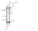
- FIG. 1 is a schematic diagram showing one embodiment of the hollow fiber membrane module of the present invention.
- FIG. 2 is a schematic flow diagram showing one form of a membrane filtration unit to which cross-flow filtration is applied.
- FIG. 3 is a schematic diagram showing a model for simulating the pressure distribution within the hollow fiber membrane module.
- FIG. 4 is a schematic flow diagram showing one form of viscosity measurement using a capillary viscometer.
- FIG. 5 is a schematic flow diagram showing one form of a membrane filtration unit for verifying simulation.
- FIG. 1 is a schematic diagram showing one embodiment of the hollow fiber membrane module of the present invention.
- directions such as “up” and “down” in this specification are based on the states shown in the drawings and are for convenience.
- the undiluted solution introduction port 2 side will be described as the downward direction.
- a container 1 having an undiluted solution inlet 2, a filtrate outlet 3, and an undiluted solution outlet 4 is filled with hollow fiber membranes 5. Both ends of the hollow fiber membrane 5 are embedded in the first potting portion 8 and the second potting portion 9 , and the first potting portion 8 and the second potting portion 9 are fixed to the container 1 . The lower end of the hollow fiber membrane 5 embedded in the first potting portion 8 is sealed. Also, the first potting part 8 has a plurality of through-holes for passing the stock solution introduced from the stock solution introduction port 2 . On the other hand, the upper end portion of the hollow fiber membrane 5 embedded in the second potting portion 9 is embedded in an open state.
- the undiluted solution inlet 2, the filtrate outlet 3, and the undiluted solution outlet 4 are cylindrical nozzles that connect the container 1 and a pipe (not shown), and are also fixed to the cylindrical container 1 in an open state. .
- the raw liquid inlet 2 is connected to the lower end of the container 1, and the filtrate outlet 3 is connected to the upper end.
- the stock solution outlet 4 is connected to the side surface of the container 1 and provided near the second potting portion 9 . Both resin and metal can be used for these materials.
- the hollow fiber membrane 5 filled in the container 1 is a hollow fibrous membrane having a liquid separation function.
- the hollow fiber membranes 5 are filled so that the axial direction of the container 1 and the axial direction of the hollow fiber membranes 5 are parallel.
- the axial direction means the longitudinal direction of the container 1 and the longitudinal direction of the hollow fiber membranes 5 .
- the first potting part 8 and the second potting part 9, in which a plurality of hollow fiber membranes are fixed with an adhesive, are potted mainly with a potting resin in which the gaps between the bundled hollow fibers are a so-called adhesive. It refers to the part filled with the agent.
- the potting part is preferably formed at the end of the hollow fiber membrane bundle.
- the potting resin which is the main component of the potting agent, epoxy resin, polyurethane resin, or silicone resin, which is excellent in adhesion to the hollow fiber membrane, heat resistance, and chemical durability, is preferable.
- the potting agent may contain additives such as silica, talc, mica, clay, calcium carbonate, glass, rubber, etc., in addition to the potting resin.
- the first potting part 8 is formed at the end of the hollow fiber membrane 5 on the undiluted solution inlet side. It is preferable that the end of the hollow fiber membrane 5 on the undiluted solution inlet side is sealed. By sealing the undiluted solution inlet side end, the filtrate flowing through the hollow portion becomes unidirectional, and on the filtrate side of the hollow fiber membrane 5, the undiluted solution inlet side end and the filtrate outlet side end are separated. can create a pressure difference between
- “sealed” means a state in which the liquid flowing inside the hollow fiber membrane 5 is not led out from the sealed end.
- the first potting part 8 is fixed to the container 1, and has a plurality of through holes for passing the stock solution introduced from the stock solution introduction port 2.
- the stock solution is introduced into the hollow fiber membrane 5 through the through holes. be done.
- the shape and number of the through-holes are not specified, and they are appropriately provided in order to suppress the occurrence of resistance and flow unevenness according to the flow rate of the stock solution to be passed.
- the first potting part 8 only needs to be positionally fixed so that the first potting part 8 does not float due to the flow of the stock solution, and may be adhesively fixed to the container 1 or may have a removable cartridge structure.
- the position fixing method is not particularly specified, and a structure for fixing the position between the container 1 and the first potting part 8 or a structure for fixing the position between the second potting part 9 and the first potting part 8 can be appropriately selected.
- the first potting part 8 is not essential if the ends of the hollow fiber membranes 5 on the side of the undiluted solution inlet are sealed. It may be a free end that is not fixed. A free end is a state in which the hollow fiber membranes are not fixed to each other with a potting agent and are freely movable.
- a method for sealing the end portion of the hollow fiber membrane 5 on the side of the undiluted solution introduction port there is a method of injecting a potting agent into the hollow portion of the hollow fiber membrane 5 for sealing, or a method of sealing the end portion by heat welding. A sealing method or the like can be applied.
- the second potting part 9 is formed at the end of the hollow fiber membrane 5 on the side of the filtrate outlet, and is fixed with the end of the hollow fiber membrane 5 on the side of the filtrate outlet being open.
- the open state means a state in which the liquid flowing inside the hollow fiber membrane is led out from the open end.
- the second potting part 9 is fixed to the container 1, but if the undiluted solution and the filtrate can be liquid-tightly separated, the second potting part 9 and the container 1 can be adhesively fixed, or a hollow container such as a so-called cartridge type can be used. A structure in which the thread membrane can be attached and detached may be employed. In the case of a cartridge type, the second potting part 9 and the container 1 may be connected via an O-ring or the like.
- the inside of the container 1 is divided into the undiluted liquid side space 6 filled with the undiluted liquid and the filtrate filled with the filtrate by the hollow fiber membranes 5 and the second potting section 9 . It is separated into side spaces 7, the undiluted solution side space 6 is a space with which the outer surface of the hollow fiber membrane 5 is in contact, and the filtrate side space 7 is a space with which the inner surface of the hollow fiber membrane 5 is in contact.
- the present invention is applied to a so-called external pressure type hollow fiber membrane module in which the raw liquid inlet 2 and the raw liquid outlet 4 are connected to the raw liquid side space 6, and the filtrate outlet 3 is connected to the filtrate side space 7. .
- Fig. 2 is a flow diagram of the membrane filtration unit.
- the stock solution is supplied from the stock solution tank 12 to the container 1 by the supply pump 14 .
- the concentrate introduced into the container 1 from the concentrate inlet 2 passes through the through hole of the first potting part 8 shown in FIG. be done. After that, it is discharged from the container 1 through the undiluted solution outlet 4 .
- This operation method is particularly suitable for filtering a stock solution containing a large amount of clogging components that accumulate on the membrane surface.
- the filtrate flow rate observed by the filtrate flow meter 32 is constant.
- the average value of the undiluted liquid introduction pressure P1 and the undiluted liquid outlet pressure P2 observed by the undiluted liquid introduction pressure gauge 41 and the undiluted liquid outlet pressure gauge 42, and the filtrate outlet pressure P3 observed by the filtrate outlet pressure gauge 43 are used. is called an average transmembrane pressure difference, and the operation is continued until the average transmembrane pressure difference reaches a predetermined pressure.
- the filtrate-side space 7 Pressure loss becomes smaller than pressure loss in the undiluted solution side space 6 .
- the raw liquid side pressure tends to be high, the filtrate side pressure to be low, and the transmembrane pressure difference at that location to be large. Therefore, the end of the hollow fiber membrane 5 on the side of the raw liquid inlet filters an excessive amount of liquid compared to the end on the side of the filtrate outlet, which is a factor in promoting fouling.
- the filtration step when performing cross-flow filtration by supplying the stock solution to the outer surface side of the hollow fiber membrane, the viscosity ⁇ f of the stock solution and the viscosity of the filtrate
- the ratio of ⁇ p is ⁇ f / ⁇ p ⁇ 1.5
- the flow rate ratio of the flow rate v f of the undiluted solution and the flow rate v p of the filtrate is 0.02 ⁇ v p /v f ⁇ 0.3.
- the pressure in the filtrate side space 7 Although the loss is smaller than the pressure loss in the undiluted solution side space 6, the flow velocity ratio between the undiluted solution flow velocity vf and the filtrate flow velocity vp (ratio of the filtrate flow velocity vp to the undiluted liquid flow velocity vf ) is set to 0.
- the required filtrate flow rate can be secured and the filtration cost can be suppressed, while the pressure loss on the undiluted solution side and the filtrate side can be homogenized, and fouling can be prevented. Progress can be suppressed.
- v p /v f ⁇ 0.3 it is possible to suppress the circulating flow rate of the stock solution from becoming excessively smaller than the flow rate of the filtrate, so that the membrane clogging component derived from the stock solution accumulates on the membrane surface.
- the required stock flow can be ensured to prevent overheating. As a result, progress of fouling can be prevented.
- the flow rate vf of the concentrate is calculated by dividing the flow rate Qc of the concentrate measured by the concentrate flowmeter 31 by the flow area Sf of the concentrate-side space 6 of the hollow fiber membrane module 10.
- FIG. The channel area Sf of the undiluted solution side space is a value obtained by subtracting the total cross-sectional area of the hollow fiber membranes 5 inserted into the container 1 from the cross-sectional area of the container 1 . Assuming that the inner diameter of the container 1 is D c , the outer diameter of the hollow fiber membranes 5 is D o , and the number of hollow fiber membranes 5 is N, the calculation is performed by the following formula (1).
- the flow velocity vp of the filtrate is calculated by dividing the flow rate Qp of the filtrate measured by the filtrate flowmeter 32 by the flow area Sp of the space 7 on the filtrate side.
- the passage area Sp of the filtrate-side space 7 is calculated by the following formula (2), where D i is the inner diameter of the hollow fiber membrane 5 .
- a feed liquid flow meter may be provided between the raw liquid inlet 2 and the feed pump 14, and the measured feed liquid flow rate Qf may be used. Also in this case, the flow velocity vf of the undiluted solution is similarly calculated.
- the values of the viscosity ⁇ f of the undiluted solution and the viscosity ⁇ p of the filtrate vary greatly depending on the temperature, it is preferable to measure the viscosity at the undiluted solution temperature measured by the undiluted solution thermometer 51 . Furthermore, since the viscosity may change due to shear caused by the flow of the undiluted solution or the filtrate, it is preferable to measure the viscosity when a shear rate ⁇ due to the flow during operation is applied.
- the shear rate ⁇ is simply calculated by the following formula (3) from the flow velocity v and the channel diameter D e .
- the channel diameter D e of the filtrate-side space 7 is the inner diameter D i of the hollow fiber membrane 5 .
- the equivalent diameter calculated by the following formula (4) is taken as the channel diameter D e .
- the viscosity measurement method a capillary viscometer is used, and the viscosity measured at the same temperature and shear rate as in actual operation is defined as the viscosity in the present invention. That is , the viscosity ⁇ is a method of measuring Using the above formula (3), the flow velocity vv in the narrow tube is set so that the shear rate in the actual operation and the shear rate in the narrow tube viscometer are the same, and the viscosity is measured.
- the thin tube viscometer there is no particular limitation as long as it can control the temperature of the tube and measure the pressure at the tube inlet and outlet, and both commercially available and self-made devices can be used.
- the ratio of the viscosity ⁇ f of the undiluted solution to the viscosity ⁇ p of the filtrate at least at the beginning of the operation is ⁇ f / ⁇ p ⁇ 1.5.
- the initial stage of operation refers to the timing when the undiluted solution is introduced into a new hollow fiber membrane module and filtration is started for the first time. is the timing to introduce and start filtration.
- the flow rate ratio between the flow rate v f of the undiluted solution and the flow rate v p of the filtrate is 0.02 ⁇ v p /v f ⁇ 0.3. , is preferable from the viewpoint of suppressing the progress of clogging.
- the flow velocity v f of the undiluted solution is preferably 0.30 m/s ⁇ v f ⁇ 1.80 m/s.
- v f ⁇ 0.30 m/s the accumulation of turbidity on the surface of the hollow fiber membrane due to the action of the stock solution flow can be suppressed, and the progress of fouling can be suppressed.
- v f ⁇ 1.80 m/s the pressure loss in the concentrate side space 6 can be suppressed, so that the concentrate side pressure applied to the end of the hollow fiber membrane 5 on the concentrate inlet side can be suppressed.
- the flow velocity v f of the stock solution is preferably 0.50 m/s ⁇ v f ⁇ 1.50 m/s, more preferably 0.70 m/s ⁇ v f ⁇ 1.30 m/s.
- the flow velocity v p of the filtrate is preferably 0.006 m/s ⁇ v p ⁇ 0.30 m/s.
- v p ⁇ 0.006 m/s the pressure loss in the filtrate side space 7 can be increased, and the pressure loss difference with the concentrate side space 6 can be reduced. Furthermore, since the filtration flux itself can be increased, the required number of membrane modules can be reduced.
- v p ⁇ 0.30 m/s the pressure loss in the filtrate side space 7 can be prevented from becoming excessively high, and the pressure loss difference with the undiluted liquid side space 6 can be reduced.
- the flow velocity v p of the filtrate is preferably 0.01 m/s ⁇ v p ⁇ 0.25 m/s, more preferably 0.03 m/s ⁇ v p ⁇ 0.20 m/s.
- the ratio of the flow velocity vf of the undiluted solution to the flow velocity vp of the filtrate is 0.02 ⁇ vp / vf ⁇ 0.3 during the entire period of the cross-flow filtration operation of the undiluted solution using the hollow fiber membrane module.
- the raw liquid flow rate v f and the filtrate flow rate v p can be controlled by adjusting the feed pump 14 , the concentrated liquid valve 21 and the filtrate valve 22 .
- the flow rate vf of the undiluted solution can be adjusted by the rotation speed of the supply pump 14 and the concentrated solution valve 21 .
- the flow velocity vp of the filtrate is affected by the transmembrane pressure difference and the flow velocity of the stock solution. Since the transmembrane pressure is the pressure difference between the raw liquid side space 6 and the filtrate side space 7, it can be controlled by adjusting the rotation speed of the supply pump 14 and the opening degrees of the concentrated liquid valve 21 and the filtrate valve 22. is.
- PID control Proportional-Integral-Differential control
- the method for operating a hollow fiber membrane module of the present invention is preferably applied to a stock solution having a viscosity ⁇ f of 3.0 mPa ⁇ s or more.
- the viscosity of the filtrate is about 1.0 mPa s. Therefore, with a stock solution of 3.0 mPa s or more, a difference from the viscosity ⁇ p of the filtrate occurs, and the effect of the operation method of the present invention is becomes more likely to occur.
- the viscosity ⁇ f of the concentrate is too high, the pressure loss in the concentrate side space 6 will increase and the operation will become difficult. It is preferably applied to a stock solution of 30.0 mPa ⁇ s or less, more preferably to a stock solution of 10.0 mPa ⁇ s or less.
- the stock solution to which the hollow fiber membrane module operation method of the present invention is applied there are no particular restrictions on the stock solution to which the hollow fiber membrane module operation method of the present invention is applied, and various stock solutions having a ratio ⁇ f / ⁇ p of the viscosity ⁇ f of the stock solution to the viscosity ⁇ p of the filtrate of 1.5 or more.
- the dissolved organic carbon (DOC) concentration is preferably 1,000 mg/L or more and 100,000 mg/L or less.
- the DOC concentration is 1,000 mg/L or more
- the stock solution contains a large amount of thickening components and is highly effective in suppressing the progress of fouling by applying the method for operating the hollow fiber membrane module of the present invention. It is preferably applied to stock solutions having a DOC concentration of 5,000 mg/L or more, more preferably 10,000 mg/L or more.
- the DOC concentration is obtained by measuring the total organic carbon (TOC) concentration of the liquid filtered through a membrane filter with a pore size of 0.45 ⁇ m.
- the TOC concentration is calculated by the TC-IC method, which is calculated by subtracting the inorganic carbon (IC) from the total carbon (TC), or by adding acid to the sample, aerating it, and measuring the total carbon in the liquid after aeration. It can be measured using the NPOC method or the like.
- the TC-IC method is calculated by subtracting the inorganic carbon (IC) from the total carbon (TC), or by adding acid to the sample, aerating it, and measuring the total carbon in the liquid after aeration. It can be measured using the NPOC method or the like.
- the TC-IC method is preferable to use the TC-IC method for measurement.
- the hollow fiber membranes 5 mounted in the hollow fiber membrane module of the present invention especially if separation can be performed so that the ratio ⁇ f / ⁇ p between the viscosity ⁇ f of the undiluted solution and the viscosity ⁇ p of the filtrate is 1.5 or more It is not limited and can be applied to various membranes such as microfiltration membranes, ultrafiltration membranes, nanofiltration membranes, reverse osmosis membranes, etc. from those with large pore sizes.
- the pressure loss when the undiluted solution permeates the membrane is much larger than the pressure loss caused by the liquid flow, and the effect of the pressure loss in the undiluted solution side space 6 and the filtrate side space 7 is small. It is preferred to apply a filtration membrane.
- the thickening component that increases the viscosity of the stock solution is often a high molecular weight component dissolved in the stock solution, it is possible to apply an ultrafiltration membrane that can separate the dissolved high molecular weight component. preferable.
- microfiltration membranes and ultrafiltration membranes there are various definitions for microfiltration membranes and ultrafiltration membranes, but they are defined as follows in the present invention. That is, a separation membrane with a pore size of 0.1 ⁇ m or more and 10 ⁇ m or less is defined as a microfiltration membrane, a separation membrane with a pore size smaller than 0.1 ⁇ m and a molecular weight cutoff of 1,000 Da or more is defined as an ultrafiltration membrane, and a molecular weight cutoff of 1,000 Da or more is defined as an ultrafiltration membrane. Separation membranes smaller than 000 Da are called nanofiltration membranes and reverse osmosis membranes.
- the hollow fiber membrane 5 used in the present invention preferably has a strength (load at break) of 500 gf/thread or more.
- a strength (load at break) of 500 gf/thread or more 500 gf/thread or more.
- FIG. 1 shows that after introducing the undiluted liquid into the hollow fiber membrane module 10 from the undiluted liquid inlet 2 of the hollow fiber membrane module 10, it is discharged from the undiluted liquid outlet 4.
- the stock solution flow is turned by 90° when it is discharged from the outlet 4 . Therefore, a shearing force perpendicular to the longitudinal direction of the hollow fiber membrane 5 is applied to the hollow fiber membrane 5 near the undiluted solution outlet 4 .
- the strength of the hollow fiber membranes 5 of 500 gf/membrane or more makes it possible to suppress fiber breakage, membrane damage, etc. against shear caused by the cross-flow velocity assumed in the present application.
- the strength is the load (gf) applied when the hollow fiber membrane 5 is stretched in the axial direction by a tensile tester or the like and is broken.
- the measured temperature at this time is the stock solution temperature during actual operation.
- the strength of the hollow fiber membrane 5 is preferably 600 gf/line or more, more preferably 700 gf/line or more.
- the strength measurement method is not particularly limited, but for example, using a tensile tester that can control the atmospheric temperature, pull a sample with a measurement length of 50 mm at a tensile speed of 50 mm / min, and change the sample 5 times or more. It can be measured by performing and calculating the average value of the breaking strength.
- the flow rate v f of the stock solution and the viscosity ⁇ f of the stock solution satisfy the relationship v f ⁇ 0.135 ⁇ f +3.0.
- the flow velocity vf of the undiluted solution is a value calculated by Equation 1, and its unit is m/s.
- the viscosity ⁇ f of the stock solution is the viscosity at the actual operating temperature, and the unit is mPa ⁇ s.
- the outer diameter Do is preferably 600 ⁇ m ⁇ D 0 ⁇ 2000 ⁇ m.
- D o ⁇ 2000 ⁇ m the membrane area per hollow fiber membrane module does not become excessively small, and the filtrate flow rate per module can be ensured.
- D o ⁇ 600 ⁇ m it is possible to suppress an excessive increase in pressure loss in the space on the side of the concentrate due to an increase in the contact area between the concentrate and the hollow fiber membrane.
- the outer diameter Do is preferably 900 ⁇ m ⁇ D 0 ⁇ 1800 ⁇ m, more preferably 1000 ⁇ m ⁇ D 0 ⁇ 1500 ⁇ m.
- the inner diameter D i of the hollow fiber membrane 5 is preferably 300 ⁇ m ⁇ D i ⁇ 1000 ⁇ m.
- the pressure loss in the filtrate-side space 7 can be controlled within an appropriate range, and the transmembrane pressure difference in the longitudinal direction of the hollow fiber membrane 5 can be reduced.
- 400 ⁇ m ⁇ D i ⁇ 900 ⁇ m is preferred, and 500 ⁇ m ⁇ D i ⁇ 800 ⁇ m is more preferred.
- the outer diameter D o and the inner diameter D i of the hollow fiber membrane 5 are obtained by cutting the hollow fiber membrane 5 with a single blade or the like along a plane perpendicular to the axial direction and observing the cross section with a microscope or the like. to measure. If the outer or inner circle is flattened, measure the length of the longest diameter (major diameter) and the shortest diameter (minor diameter), and calculate by averaging both. .
- the hollow fiber membranes 5 loaded in the hollow fiber membrane module 10 are arbitrarily cut, and the values obtained by averaging the outer diameter and inner diameter of 10 or more hollow fiber membranes are preferably used.
- the filling rate M of the hollow fiber membranes 5 loaded in the hollow fiber membrane module 10 is preferably 25% ⁇ M ⁇ 45%. By satisfying 25% ⁇ M ⁇ 45%, it is possible to control the pressure loss on the undiluted solution side within an appropriate range while ensuring the membrane area per module.
- the filling rate M is preferably 28% ⁇ M ⁇ 42%, more preferably 30% ⁇ M ⁇ 40%.
- the filling rate M is calculated from the inner diameter D c of the container 1, the outer diameter D o of the hollow fiber membranes 5, and the number N of the hollow fiber membranes 5 by the following formula (6). If there is a member other than the hollow fiber membrane 5 existing in the concentrate side space 6 in the container 1, the cross-sectional area of that member perpendicular to the axial direction of the container 1 is calculated, and the exclusive area S of the hollow fiber membrane 5 is calculated. Calculate in addition to p .
- the membrane length L is the portion of the hollow fiber membrane 5 that is actually used for filtration when the hollow fiber membrane 5 is filled in the container 1, that is, the portion that the outer surface of the hollow fiber membrane 5 is in contact with the stock solution. is the length of In FIG. 1, it is the length of the hollow fiber membrane 5 from the end face of the first potting part 8 on the second potting part side to the end face of the second potting part 9 on the first potting part side.
- the length of the hollow fiber membranes embedded in the first potting portion 8 and the second potting portion 9 is not considered here.
- the film length L is preferably 0.50 m ⁇ L ⁇ 2.00 m.
- the film length L is preferably 0.70 m ⁇ L ⁇ 1.50 m, more preferably 0.80 m ⁇ L ⁇ 1.20 m.
- the membrane length L is actually used for filtration.
- half of the length of the hollow fiber membrane to be treated that is, half of the length of the fiber at the portion where the outer surface of the hollow fiber membrane is in contact with the stock solution.
- the portion of the free end that is not subjected to the adhesive or heat sealing treatment is connected to the first potting portion 8 .
- 2 is the length up to the end face of the potting portion 9 on the undiluted solution inlet side.
- the membrane length L is the portion of the hollow fiber membrane that is actually used for filtration, that is, the portion where the outer surface of the hollow fiber membrane comes into contact with the stock solution. , may be measured as the length in the direction parallel to the container 1 .
- the method for operating a hollow fiber membrane module of the present invention in addition to the above-described filtration step, preferably further includes a backwash step in which a washing liquid is caused to flow from the inner surface side to the outer surface side of the hollow fiber membranes.
- the surface pore diameter ⁇ o of the outer surface of the hollow fiber membrane is 0.005 ⁇ m ⁇ ⁇ o ⁇ 0.02 ⁇ m, and the ratio of the surface pore diameter ⁇ i of the inner surface of the hollow fiber membrane to the surface pore diameter ⁇ o of the outer surface is Preferably, ⁇ i / ⁇ o >50.
- components larger than the pores on the surface of the hollow fiber membrane are deposited on the surface of the hollow fiber membrane 5.
- components contained in the undiluted solution that are smaller than the pores on the surface of the hollow fiber membrane enter into the pores. This causes clogging on the membrane surface and inside the membrane.
- components deposited on the membrane surface are removed by the flow generated by the cross-flow filtration operation.
- a backwashing step in which the cleaning liquid is passed from the inner surface side toward the outer surface side of the hollow fiber membrane.
- the backflow washing step for example, using a compressed gas, a pump, or the like from the filtrate tank 13, the washing liquid is passed through the filtrate-side space 7 of the hollow fiber membrane module 10, and the washing liquid flowing out to the undiluted liquid-side space 6 is passed through the hollow It is a step of discharging to the outside of the fiber membrane module 10 .
- clogging components in the stock solution are held in the space on the side of the stock solution by the hollow fiber membrane, and adhere to the membrane surface. , clogging components tend to accumulate in the pores near the surface.
- the surface pore diameter ⁇ o of the outer surface of the hollow fiber membrane is preferably 0.005 ⁇ m ⁇ ⁇ 0 ⁇ 0.02 ⁇ m.
- the pore diameter ⁇ o is more preferably 0.005 ⁇ m ⁇ ⁇ 0 ⁇ 0.009 ⁇ m, and particularly preferably 0.005 ⁇ m ⁇ ⁇ 0 ⁇ 0.008 ⁇ m.
- the surface pore size in the present invention is obtained by the following method. Images of the outer and inner surfaces of the hollow fiber membrane observed with a scanning electron microscope (SEM) or a transmission electron microscope (TEM) are binarized using free software "ImageJ". When binarizing, after creating a background with 1 pixel in Subtract Background, select the condition: RenyiEntropy in Threshold (threshold for binarization). In the obtained binarized image, by selecting Area in Analyze Particles, the area of each hole is obtained, and the diameter is calculated assuming that each hole is a circle. The surface pore diameter is determined by averaging the pore diameters of 100 or more pores.
- the surface pore diameter may be obtained from the cross-sectional pore diameter described later.
- the surface pore size is defined as the cross-sectional pore size at a depth of 20 ⁇ m or less from the surface.
- the ratio of the pore diameter ⁇ i of the inner surface of the hollow fiber membrane, which is the surface in contact with the filtrate, to the pore diameter of the outer surface ⁇ o , which is the surface of the hollow fiber membrane in contact with the stock solution (the ratio of the pore diameter ⁇ i of the inner surface to the pore diameter of the outer surface ⁇ o
- the ratio ⁇ i / ⁇ o is preferably ⁇ i / ⁇ o >50.
- ⁇ i / ⁇ o >60 is preferred, and ⁇ i / ⁇ o >70 is particularly preferred.
- the cleaning liquid used in the backwash process it is preferable to use a liquid with a lower viscosity than the stock solution, such as pure water or filtrate, as this will facilitate the cleaning effect.
- the backwashing process can be performed during the operation of the cross-flow filtration, after the operation is stopped, etc., and the frequency thereof may be appropriately set according to the conditions during the operation.
- the hollow fiber membrane 5 of the present invention may be a single-layer hollow fiber membrane, but a composite hollow fiber membrane in which two or more layers are laminated is preferable because ⁇ i / ⁇ o can be easily obtained.
- Lp i ⁇ Lp o between the transmission coefficient Lp o of the layer on the outer surface side and the transmission coefficient Lp i of the layer on the inner surface side.
- the permeability coefficient Lp is an index of ease of passage of water, and is represented by the following formula (7).
- Formula (7) is described, for example, in Journal of Chemical Engineering of Japan (Vol. 15, No. 3 (1982) pp. 200-205).
- the cross-sectional pore size is indicated by the radius instead of the diameter, and the porosity is indicated by the open area ratio, but they are used in the same meaning.
- the pure water permeability K which will be described later, is an index of the ease with which water can pass, like the permeability coefficient Lp. The difference is that Lp is calculated from the microstructure of the separation membrane. The permeability coefficient Lp is only used to compare the water permeability in each layer.
- ⁇ is the cross-sectional pore diameter ( ⁇ m)
- A is the porosity (-)
- ⁇ is the viscosity of water (Pa ⁇ s)
- H is the thickness ( ⁇ m).
- the permeability coefficient Lp i of the layer on the inner surface side is larger than the permeability coefficient Lp o of the layer on the outer surface side, the pressure loss of the cleaning liquid passing through the layer on the inner surface side can be reduced during backwashing. It is possible to increase the pressure acting on the layer on the outer surface side where clogging components tend to accumulate, thereby enhancing the cleaning effect.
- the cross-sectional pore size of the present invention can be obtained by the following method.
- the cross-sectional sample for observation is a hollow fiber membrane embedded using a commercially available embedding agent for preparing frozen tissue sections, and a cryo-ultramicrotome is used to take a section of the porous membrane at a low temperature with a thickness of 100 nm. It is obtained by vacuum drying overnight.
- a cross section of the hollow fiber membrane is observed with a scanning electron microscope (SEM) or a transmission electron microscope (TEM) to obtain an image of each layer. If the layer structure is symmetrical in the film thickness direction, an image of the central part of the layer is obtained. get. After that, it is binarized using free software "ImageJ".
- Threshold for binarization.
- the area of each hole is obtained, and the diameter is calculated assuming that each hole is a circle.
- the cross-sectional pore size is obtained by averaging the pore sizes of 100 or more pores.
- the porosity A can also be obtained from the binarized image of the cross section of the hollow fiber membrane described above. Calculate the rate.
- the permeability coefficient Lp is calculated at intervals of 10 ⁇ m in the film thickness direction, and the values calculated at intervals of 10 ⁇ m are used for the cross-sectional pore diameter and the gap. Further, when the structure of each layer is symmetrical in the film thickness direction, the transmission coefficient Lp calculated in the region located at the center of each layer in the film thickness direction is set as the Lp of the layer, and the structure of each layer is the film thickness. In the case of asymmetry in the thickness direction, the permeability coefficient Lp calculated in the region where the cross-sectional pore diameter is the densest in the thickness direction is taken as the Lp of the layer.
- the thickness H o of the layer with a small transmission coefficient on the outer surface side and the thickness H i of the layer with a large transmission coefficient on the inner surface side satisfy H o /H i ⁇ 1.0.
- H o /H i ⁇ 1.0 pressure loss occurring in a layer with a small permeability coefficient can be reduced.
- H o / H i is too small , the separation function for blocking the thickening component is lowered . ⁇ 0.4 is more preferred.
- the composite hollow fiber membrane composed of two layers preferably has a spherical structure layer on the inner surface side and a three-dimensional network structure layer on the outer surface side.
- the thickness of the three-dimensional network structure layer depends on the above-described cleaning effect and the thickening component. from the viewpoint of the blocking property, the thickness is preferably 20 ⁇ m or more and 120 ⁇ m or less, more preferably 30 ⁇ m or more and 80 ⁇ m or less. If the thickness of the three-dimensional network structure layer is less than 20 ⁇ m, the rejection rate of the thickening component may decrease. When the thickness is more than 120 ⁇ m, the permeation resistance becomes too large, which may cause a decrease in cleaning effect and a decrease in water permeability.
- the thickness of the spherical structure layer is also preferably 120 ⁇ m or more and 500 ⁇ m or less, more preferably 200 ⁇ m or more and 300 ⁇ m or less, from the viewpoint of the washing effect described above and the strength and water permeability of the hollow fiber membrane.
- a liquid-liquid thermally induced phase separation method or a non-solvent induced phase separation method, which will be described later, can be used to form the three-dimensional network structure layer, and a solid-liquid thermally induced phase separation method can be used to form the spherical structure layer. can be used.
- polymer material for the hollow fiber membrane 5 examples include polyethylene, ethylene-propylene copolymer, ethylene-ethyl acrylate copolymer, ethylene-vinyl acetate copolymer, ionomer, polypropylene, and poly-4-methyl.
- Olefin-based polymers such as pentene-1, fluorine-containing polymers such as polytetrafluoroethylene, polychlorotrifluoroethylene, polyvinylidene fluoride, tetrafluoroethylene-ethylene copolymers or tetrafluoroethylene-perfluoroalkyl vinyl ether copolymers , cellulose-based polymers such as cellulose acetate, polyvinyl chloride, acrylonitrile-based polymers, silicone-based polymers, polyamides, polyimides, polyethersulfones, polysulfones, polyphenylene oxides, polyphenylene sulfides, polyarylates, polyetheretherketones, polyetherimides, polycarbonates Or a polyvinyl alcohol-based polymer may be mentioned.
- fluorine-containing polymers such as polytetrafluoroethylene, polychlorotrifluoroethylene, polyvinylidene fluoride, tetrafluoroethylene
- a fluororesin-based polymer, polyethersulfone or polysulfone is preferable in order to increase the heat resistance, physical strength and chemical durability of the resulting hollow fiber membrane, but the hollow fiber membrane module for cross-flow filtration imposes a large load on the membrane.
- fluororesin-based polymers having excellent strength are preferred.
- a hydrophilic polymer may be included in order to reduce fouling of the hollow fiber membrane 5.
- specific examples include polymers containing vinyl alcohol, ethylene glycol, vinylpyrrolidone, methacrylic acid, allyl alcohol, cellulose, and vinyl acetate.
- the copolymer containing a hydrophilic group includes polyvinyl alcohol having a saponification degree of less than 99%, a vinylpyrrolidone/vinyl acetate copolymer, a vinylpyrrolidone/vinylcaprolactam copolymer, and a vinylpyrrolidone/vinyl alcohol copolymer. polymerization polymer, and the like.
- Method for producing hollow fiber membrane As an example of the method for producing a hollow fiber membrane according to the present invention, a method for producing a hollow fiber membrane using a fluororesin-based polymer will be described. Various methods such as a thermally induced phase separation method and a non-solvent induced phase separation method can be used as a method for producing a hollow fiber membrane using a fluororesin polymer. A manufacturing method using a thermally induced phase separation method is shown below.
- a fluororesin-based polymer solution that is, containing the fluororesin-based polymer Prepare the membrane-forming stock solution.
- a high-strength porous hollow fiber membrane can be obtained when the polymer concentration in the membrane-forming stock solution is high.
- the concentration of the fluororesin polymer is preferably 20% by weight or more and 60% by weight or less, more preferably 30% by weight or more and 50% by weight or less.
- the term "poor solvent” means that a fluororesin polymer cannot be dissolved at a low temperature of 60° C. or lower by 5% by weight or more, but is 60° C. or higher and the melting point of the fluororesin polymer It is a solvent capable of dissolving 5% by weight or more in a high temperature range of about 178° C. when the molecule is composed of vinylidene fluoride homopolymer alone.
- a good solvent is a solvent capable of dissolving 5% by weight or more of a fluororesin-based polymer even in a low temperature range of less than 60°C. It is defined as a solvent that neither dissolves nor swells the resinous polymer.
- cyclohexanone, isophorone, ⁇ -butyrolactone, methyl isoamyl ketone, propylene carbonate, dimethyl sulfoxide, etc., and mixed solvents thereof can be mentioned as poor solvents for fluororesin-based polymers.
- Good solvents include N-methyl-2-pyrrolidone, dimethylacetamide, dimethylformamide, methyl ethyl ketone, acetone, tetrahydrofuran, tetramethyl urea, trimethyl phosphate and mixed solvents thereof.
- Non-solvents include water, hexane, pentane, benzene, toluene, methanol, ethanol, carbon tetrachloride, o-dichlorobenzene, trichloroethylene, ethylene glycol, diethylene glycol, triethylene glycol, propylene glycol, butylene glycol, pentanediol, Aliphatic hydrocarbons such as hexanediol, low molecular weight polyethylene glycol, aromatic hydrocarbons, aliphatic polyhydric alcohols, aromatic polyhydric alcohols, chlorinated hydrocarbons, or other chlorinated organic liquids and their mixed solvents, etc. is mentioned.
- thermally induced phase separation methods that induces phase separation by temperature change is used to obtain a hollow fiber membrane from a membrane-forming stock solution containing a fluororesin-based polymer.
- Thermally induced phase separation methods mainly utilize two types of phase separation mechanisms.
- One is a liquid-liquid phase in which a polymer solution that is homogeneously dissolved at high temperature separates into a polymer-rich phase and a polymer-dilute phase due to the decrease in dissolving ability of the solution when the temperature is lowered, and then the structure is fixed by crystallization. Separation method.
- the other is a solid-liquid phase separation method in which a polymer solution uniformly dissolved at a high temperature is phase-separated into a polymer solid phase and a solvent phase due to crystallization of the polymer when the temperature is lowered.
- the former method mainly forms a three-dimensional network structure
- the latter method forms a spherical structure mainly composed of spherical tissue.
- the latter phase separation mechanism is preferably used as a hollow fiber membrane for cross-flow filtration, which requires strength.
- polymer concentrations and solvents are selected that induce solid-liquid phase separation.
- the hollow portion-forming liquid is discharged from the inner tube of the double-tube type spinneret.
- Dispense. A porous hollow fiber membrane is obtained by cooling and solidifying the membrane-forming undiluted solution thus discharged in a cooling bath.
- the cooling bath for cooling the fluororesin-based polymer solution discharged from the die will be described.
- the cooling bath it is preferable to use a mixed liquid containing a poor solvent or a good solvent with a concentration of 50 to 95% by weight and a non-solvent with a concentration of 5 to 50% by weight.
- the same poor solvent as the polymer solution as the poor solvent.
- the cooling bath it is preferable to use a mixed liquid composed of a poor solvent or a good solvent with a concentration of 50 to 95% by weight and a non-solvent with a concentration of 5 to 50% by weight.
- the same poor solvent as the polymer solution as the poor solvent.
- a hollow fiber membrane comprising a fluororesin-based polymer obtained by the above method may be stretched. The stretching ratio and stretching temperature are appropriately selected depending on the desired pore diameter, size and pure water permeability.
- the inner and outer diameters of the hollow fiber membranes are adjusted mainly by adjusting the diameter of the double-tube spinneret and the discharge rate of the undiluted membrane-forming solution and the hollow portion-forming liquid.
- the dimensions can also be adjusted by changing the draw ratio and draw temperature.
- a method of obtaining a composite hollow fiber membrane there are a method of forming multiple layers simultaneously and a method of sequentially forming other layers on a single-layer hollow fiber membrane.
- the former method for example, there is a method of composite molding a plurality of resin solutions using a multi-tube spinneret.
- a method of spray coating the solution There is a method of spray coating the solution.
- the method of applying a resin solution for forming other layers, scraping off the resin solution, and then solidifying the resin solution is simple and preferable.
- the resin solution forming the other layers is not particularly limited, but a three-dimensional network structure is preferably used for the purpose of modifying or densifying the surface of the separation membrane. be done.
- a non-solvent-induced phase separation method can be used to form the three-dimensional network structure.
- the non-solvent-induced phase separation is phase separation in which a resin solution is solidified by contact with a non-solvent.
- the solvent for the resin solution is preferably a good solvent for the resin. , methyl ethyl ketone, acetone, lower alkyl ketones such as tetrahydrofuran, esters, amides, etc. and mixed solvents thereof.
- the good solvent is a solvent capable of dissolving 5% by weight or more of the polyvinylidene fluoride resin even at a low temperature of less than 60°C.
- a non-solvent is defined as a solvent that neither dissolves nor swells the polyvinylidene fluoride resin up to the melting point of the polyvinylidene fluoride resin or the boiling point of the solvent.
- non-solvents for polyvinylidene fluoride resins include water, hexane, pentane, benzene, toluene, methanol, ethanol, carbon tetrachloride, o-dichlorobenzene, trichloroethylene, ethylene glycol, diethylene glycol, triethylene glycol, and propylene.
- Aliphatic hydrocarbons such as glycols, butylene glycols, pentanediol, hexanediol, low molecular weight polyethylene glycols, aromatic hydrocarbons, aliphatic polyhydric alcohols, aromatic polyhydric alcohols, chlorinated hydrocarbons, or other chlorinated Examples include organic liquids and mixed solvents thereof.
- the types of hollow fiber membrane modules include a container-integrated module in which the container 1 and the hollow fiber membranes 5 are fixed with an adhesive, and a container-integrated module in which the container 1 and the hollow fiber membranes 5 are not fixed with an adhesive, and the hollow fiber membranes 5 are separated from the container 1. It is divided into detachable cartridge type modules.
- a plurality of hollow fiber membranes 5 are inserted into the container 1, and the ends of the hollow fiber membranes 5 and the container 1 are fixed with an adhesive.
- the hollow fiber membranes are inserted into a special jig or the like, and the membranes are adhered to each other with an adhesive, and are not fixed to the container 1 .
- the hollow fiber membrane 5 is inserted into a fixing jig or container, or both, and an adhesive is poured into it to fix it.
- Methods for filling the gaps between the hollow fiber membranes with the adhesive include, for example, a centrifugal potting method in which the potting agent permeates using centrifugal force, or a static potting method in which the adhesive permeates by natural flow. .
- the adhesive may be injected into a casting mold to fill the gaps between the hollow fiber membranes.
- the end of the hollow fiber membrane 5 When opening the end of the hollow fiber membrane fixed with an adhesive, the end of the hollow fiber membrane 5 is sealed in advance so that the adhesive does not flow into the hollow part of the hollow fiber membrane when the adhesive is poured. and secure with adhesive.
- Sealing methods include a method of injecting an adhesive only into the hollow portion, a method of welding with heat or a solvent, and the like. After fixing the hollow fiber membranes 5 with sealed ends with an adhesive, it is possible to open the hollow fiber membranes 5 by cutting the other end side from the sealed part in the cross-sectional direction. If the ends of the hollow fiber membrane are fixed with an adhesive without being sealed, the adhesive flows into the hollow portion of the hollow fiber membrane 5, so that the ends are sealed.
- a method of fixing both ends of the hollow fiber membrane 5 with an adhesive may be adopted, but the end of the hollow fiber membrane 5 on the side of the undiluted solution inlet may be a free end that is not fixed with an adhesive. .
- FIG. 3 shows the model outline for the simulation.
- FIG. 3(a) shows one hollow fiber membrane 5 and the flow of the stock solution and the filtrate.
- the undiluted solution is indicated by a hatched arrow
- the filtrate is indicated by an open arrow.
- the end of the hollow fiber membrane 5 on the side of the undiluted solution inlet is sealed, and the end on the side of the filtrate outlet is open, so that all the filtrate is led out from the end on the side of the filtrate outlet.
- FIG. 3(a) shows one hollow fiber membrane 5 and the flow of the stock solution and the filtrate.
- the undiluted solution is indicated by a hatched arrow
- the filtrate is indicated by an open arrow.
- n is an integer of 0 or more
- k is a natural number of 1 or more.
- the filtrate drawn out from the minute section n ⁇ 1 and the filtrate filtered by the membrane in the minute section n join.
- the filtrate flow rate Q i,n derived from the minute section n the filtrate amount derived from the minute section n ⁇ 1 is Q i,n ⁇ 1
- the filtrate filtered by the membrane in the minute section n is
- the filtrate flow rate Q p,n in the minute interval n is determined by the undiluted solution side pressure P o,n and the filtrate side pressure P i,n in the minute interval n, the membrane area A n , the membrane filtration resistance R n , and the filtration temperature It is calculated from the following equations (9) to (11) from the viscosity ⁇ p of the filtrate at .
- the undiluted solution side pressure P o,n in the minute section n is calculated by the following formula (12), taking into consideration the undiluted solution introduction pressure P o,0 and the pressure loss ⁇ P 0 ⁇ l n caused by the undiluted solution flow. Since part of the stock solution is actually filtered by the membrane, the circulation flow rate varies in the axial direction of the hollow fiber membranes 5, but this can be ignored because the flow rate to be filtered is small relative to the circulation flow rate. Therefore, in this model, the pressure loss ⁇ P o per unit length in the axial direction caused by the flow of the stock solution is calculated as being constant regardless of the position.
- the pressure loss ⁇ P o per unit length is calculated from the equivalent diameter D e of the undiluted solution side space 6 and the viscosity ⁇ f of the undiluted solution using the following equations (13) and (14). Note that ⁇ is the density of the concentrate, Dc is the diameter of the inner circle of the container 1, and ⁇ is the shape correction coefficient of the concentrate-side channel.
- the filtrate side pressure P i,n in the minute section n is calculated from the pressure loss when flowing inside the hollow fiber membrane 5 .
- the Reynolds number Re i,n of the filtrate flowing inside the hollow fiber membrane 5 is calculated, and the pressure loss from the minute section n to the end on the filtrate outlet side is integrated.
- v p,n is the flow velocity of the filtrate in the minute interval n.
- the following formulas (15) and (16) show the calculation method when the flow inside is assumed to be laminar.
- the difference between the undiluted solution side pressure P o,n and P i,n in the minute section n is the transmembrane pressure ⁇ P m,n in that section.
- ⁇ P m,k ⁇ P m,0 which is the transmembrane pressure difference in the axial direction of the hollow fiber membrane 5, is 50 kPa or less.
- the pure water permeation performance K was measured by fabricating a miniature module composed of three hollow fiber membranes with a membrane length of 0.1 m. External pressure dead end filtration of reverse osmosis membrane filtered water was performed for 10 minutes under conditions of a temperature of 25° C. and a filtration differential pressure of 16 kPa to determine the permeation amount (m 3 ). The permeation amount (m 3 ) is converted into a value per unit time (h) and effective membrane area (m 2 ), and further multiplied by (50/16) to convert to a value at a pressure of 50 kPa. A permeation performance K was obtained.
- the effective membrane area is the area of the portion of the outer surface of the hollow fiber membrane 5 that is actually used for filtration.
- measuring strength Using a tensile strength tester (TENSILON (registered trademark) / RTM-100, manufactured by Toyo Baldwin Co., Ltd.), a sample with a measurement length of 50 mm is pulled in an atmosphere of 25 ° C. at a speed of 50 mm / min, and the sample is changed. Five or more tests were performed, and the average value was calculated.
- TENSILON registered trademark
- RTM-100 manufactured by Toyo Baldwin Co., Ltd.
- Viscosity was measured using the apparatus shown in FIG.
- a stock solution tank 12 and a thin tube 16 were placed in a constant temperature water bath 15 and connected with a fluorine tube so that the stock solution could be sent to and returned from the thin tube 16 .
- a fluorine tube having an inner diameter of 2.0 mm and a tube length of 1.0 m was used as the thin tube 16 .
- a tube inlet pressure gauge 45 and a tube outlet pressure gauge 46 were connected to both ends of the thin tube. Water was filled in the constant temperature water tank 15, and the temperature of the undiluted solution was adjusted to the same temperature as during actual operation.
- the shear rate is obtained from the channel diameter D e and the flow rate v of the hollow fiber membrane module used in actual operation, and the flow rate v v of the undiluted solution sent to the thin tube so that the shear rate is equivalent to the shear rate ⁇ of the actual module . It was set.
- the stock solution was fed at the set flow rate vv , and the viscosity was calculated using equation (5) from the measured tube inlet pressure P1 and tube outlet pressure P2.
- the cross-sectional pore size was measured by using a cryo-ultramicrotome (Leica; FC7) with a hollow fiber membrane embedded using a commercial embedding agent for preparing frozen tissue sections (manufactured by Tissue Tech; O.C.T. Compound).
- a 100 nm-thick slice was taken from the porous membrane in the direction perpendicular to the surface at ⁇ 40° C., and vacuum-dried overnight at room temperature.
- the cross section of the hollow fiber membrane is observed with SEM (manufactured by Hitachi High-Technologies Corporation; S-5500) or TEM (manufactured by JEOL Ltd.; JEM-1400Plus), an image is obtained, and two images are obtained using the free software "ImageJ". valued.
- an apparatus comprising a double-tube mouthpiece, a pipe connected to the mouthpiece, and two gear pumps arranged on the pipe was used.
- the raw material liquid was retained at 100 to 103° C. for 15 seconds while being pressurized to 2.5 MPa. Thereafter, while the ⁇ -butyrolactone 85% by weight aqueous solution was discharged from the inner tube of the double-tube spinneret, the raw material liquid was discharged from the outer tube.
- the raw material liquid was retained for 20 seconds in a cooling bath containing 85% by weight of ⁇ -butyrolactone aqueous solution at a temperature of 5° C. to solidify. Then, the hollow fiber membrane obtained above was stretched 1.5 times in water at 95° C. to obtain a support layer.
- a composite membrane was obtained by applying a functional layer to the support layer obtained above.
- the functional layer contains 12% by weight of a vinylidene fluoride homopolymer having a weight average molecular weight of 284,000, 7.2% by weight of cellulose acetate (Eastman Chemical Co., CA435-75S), and N-methyl-2-pyrrolidone.
- a polymer solution was prepared by mixing and dissolving at a temperature of 95° C. at a rate of 80.8% by weight.
- This membrane-forming stock solution was evenly applied to the surface of the hollow fiber membrane having a spherical structure, and immediately solidified in a coagulation bath containing 100% water to form a three-dimensional network structure layer on the spherical structure layer.
- a thread membrane was produced.
- the resulting hollow fiber membrane had an outer diameter of 1.30 mm, an inner diameter of 0.75 mm, a pure water permeability of 0.4 m/hr, and a tenacity of 1010 g/membrane.
- the pore diameter ⁇ o of the outer surface was calculated to be 0.006 ⁇ m from the binarized SEM image
- the pore diameter ⁇ i of the inner surface was calculated to be 0.6 ⁇ m from the cross-sectional pore diameter
- ⁇ i / ⁇ o was 100.
- the thickness Li of the spherical structure layer was 0.225 mm.
- Reference example 2 In Reference Example 1, the temperature of the coagulation bath for solidifying the membrane-forming stock solution for the functional layer was adjusted to produce a hollow fiber membrane having a pore diameter of 0.010 ⁇ m on the outer surface. At this time, the outer diameter was 1.30 mm, the inner diameter was 0.75 mm, the pure water permeability coefficient was 0.6 m/hr, the strength was 1010 g/wire, and ⁇ i / ⁇ o was 60.
- the polymer solution prepared from the outer tube of the double-tube type spinneret is coagulated in a 100% water coagulation bath while discharging the injection liquid made of 100% water from the inner tube of the double-tube type spinneret.
- a hollow fiber membrane consisting of layers with a three-dimensional network structure was produced by The resulting hollow fiber membrane had an outer diameter of 1.30 mm, an inner diameter of 0.75 mm, a pure water permeability of 0.5 m/hr, a strength of 230 g/membrane, and an outer surface pore diameter of 0.008 ⁇ m. , ⁇ i / ⁇ o was 1.13.
- the resulting hollow fiber membrane 5 was cut to a length of 1.2 m, immersed in a 30% by mass glycerin aqueous solution for 1 hour, and air-dried. After that, a silicone adhesive (SH850A/B manufactured by Dow Corning Toray Co., Ltd., a mixture of two agents in a mass ratio of 50:50) was used to seal the end of the hollow fiber membrane on the filtrate outlet side.
- a silicone adhesive SH850A/B manufactured by Dow Corning Toray Co., Ltd., a mixture of two agents in a mass ratio of 50:50
- the above-mentioned hollow fiber membrane 5 is attached to the container 1 (inner diameter 97.6 mm, length 1100 mm) so that the sealed filtrate outlet side end is on the filtrate outlet 3 side. filled.
- a raw liquid outlet 4 is provided on the side of the container 1 on the side of the filtrate outlet 3 .
- a first potting part forming jig was attached to the undiluted solution inlet 2 side of the container 1, and a second potting part forming jig was attached to the filtrate outlet 3 side.
- a pin having a diameter of 7 mm and a length of 100 mm is inserted in the first potting part forming jig in the same direction as the axial direction of the hollow fiber membrane 5 in order to open a through hole for introducing the concentrate into the concentrate side space 6. bottom.
- a bisphenol F type epoxy resin manufactured by Huntsman, LST868-R14
- an aliphatic amine curing agent manufactured by Huntsman, LST868-H14
- the centrifugal molding machine is rotated, and the potting agent is filled into the first potting portion forming jig and the second potting portion forming jig at both ends to form the first potting portion 8 and the second potting portion 9, and the potting agent is was cured.
- the temperature in the centrifugal molding machine was 35° C.
- the rotation speed was 300 rpm
- the centrifugation time was 5 hours.
- the first potting part forming jig, the second potting part forming jig and the pin are removed, and after curing at room temperature for 24 hours, the end of the second potting part 9 is cut with a tipped rotary blade to form a hollow.
- the end surface of the fiber membrane 5 on the filtrate outlet side was opened.
- the hollow fiber membrane had a membrane length L of 1.0 m, a filling rate M of 40%, and a membrane area of 9.2 m 2 .
- the filtration unit shown in FIG. 2 was used for the filtration test using the hollow fiber membrane module obtained above.
- the volume of the undiluted solution tank 12 is 200 L, and the supply pump 14 is operated to introduce the undiluted solution into the hollow fiber membrane module. All of the unfiltered stock solution was returned to the stock solution tank 12 from the stock solution outlet 4 .
- the filtrate sent to the filtrate tank 13 was returned to the undiluted solution tank 12 by a pump each time, and the water level of the undiluted solution tank was controlled so as not to decrease.
- the transmembrane pressure here is measured by the filtrate outlet pressure gauge 43 from the average value of the undiluted liquid introduction pressure measured by the undiluted liquid introduction pressure gauge 41 and the undiluted liquid outlet pressure measured by the undiluted liquid outlet pressure gauge 42. It was calculated by subtracting the filtrate outlet pressure.
- the operation was performed with the filtrate outlet pressure fixed at 20 kPa . A value obtained by dividing the pressure difference by 0.1 m 3 /m 2 (unit is kPa/m and hereinafter described) was used.
- the hollow fiber membranes obtained above were used to prepare another hollow fiber membrane module different from the above.
- a fluorine tube having an inner diameter of 6 mm was used as the container 1, and 15 hollow fiber membranes obtained above were potted with both ends opened so that the membrane length L was 1.0 m.
- the filling rate M at this time was 32%.
- the undiluted solution inlet 2 and the undiluted solution outlet 4 are connected to the side surface of the tube, and the undiluted solution introduced from the undiluted solution inlet 2 flows through the container 1 parallel to the axial direction of the hollow fiber membranes 5. It flows in the direction and is discharged from the undiluted solution outlet 4 .
- the pressure measured by the raw solution introduction pressure gauge 41 was defined as the raw solution introduction pressure Po ,0
- the pressure measured by the raw solution discharge pressure gauge 42 was defined as the raw solution discharge pressure P o,k .
- a pressure gauge is connected to each of the open ends.
- the pressure measured by the filtrate introduction pressure gauge 44 on the other end side was defined as the filtrate introduction pressure P i , 0 .
- a filtration test was conducted using this miniature module.
- a 0.3 wt % aqueous solution of polyethylene glycol (molecular weight: 2,000,000, manufactured by Fujifilm Wako Pure Chemical Industries, Ltd.) dissolved in distilled water was used as a stock solution.
- the stock solution was stirred with a stirrer overnight to dissolve, and the viscosity of the stock solution after dissolution was measured at 25° C. to find that the viscosity was 5.0 mPa ⁇ s.
- the stock solution was supplied to the miniature module by the supply pump 14, and cross-flow filtration was performed.
- the operating conditions at this time were a stock solution flow rate of 1.0 m/s and a filtrate flow rate of 0.045 m/s (equivalent to a filtration flux of 0.4 m/d).
- the temperature of the stock solution was 25°C. Filtration was started under these operating conditions, and each pressure was measured immediately after the start of filtration to calculate ⁇ P m,0 and ⁇ P m,k . When the viscosity of the filtrate collected during this test was measured in the same manner, the viscosity was 1.0 mPa ⁇ s.
- ⁇ P m,0 and ⁇ P m,k were also calculated from simulation using equations (8) to (17).
- Various parameters of the hollow fiber membrane 5 used for manufacturing the miniature module were input to the simulation.
- Filtrate outlet pressure P o,k was also calculated using measurements obtained from testing miniature modules.
- ⁇ l was set to 10 mm, and the shape correction coefficient ⁇ of the undiluted solution side channel was set to 1.0.
- Example 1 Using a hollow fiber membrane module loaded with the hollow fiber membranes of Reference Example 1, filtration was performed using an aqueous polyethylene glycol solution.
- the polyethylene glycol aqueous solution was prepared by adding polyethylene glycol (molecular weight: 2,000,000, manufactured by Fuji Film Wako Pure Chemical Industries, Ltd.) to 0.3 wt % in distilled water. At this time, the stock solution had a temperature of 25° C. and a viscosity of 5.0 mPa ⁇ s.
- Filtration was started by adjusting the flow velocity vf of the undiluted solution to 1.0 m/s and the flow velocity vp of the filtrate to 0.03 m/s (equivalent to 0.3 m/d as filtration flux).
- the rate of increase of the transmembrane pressure difference was 230 kPa/m, and the operation could be performed while suppressing the increase of the transmembrane pressure difference.
- the viscosity of the filtrate immediately after the start of filtration was 1.0 mPa ⁇ s.
- the pressure distribution inside the module was calculated by simulation.
- the calculation method was the same as the method described in Reference Example 1.
- the axial transmembrane pressure difference ⁇ P m,0 ⁇ P m,k of the hollow fiber membrane 5 was as low as 43 kPa.
- Example 2 Except for adjusting the flow velocity v p of the filtrate to 0.05 m / s (equivalent to 0.5 m / d as the filtration flux), the filtration test and the inside of the module were performed in the same manner as the method described in Example 1. A pressure distribution simulation was carried out.
- the rate of increase in the transmembrane pressure difference was 250 kPa/m, and the operation could be performed while suppressing the increase in the transmembrane pressure difference.
- the transmembrane pressure difference ⁇ P m,0 ⁇ P m,k was a low value of 43 kPa.
- Example 3 Except for adjusting the flow velocity v p of the filtrate to 0.11 m / s (corresponding to 1.0 m / d as the filtration flux), the filtration test and the inside of the module were performed in the same manner as described in Example 1. A pressure distribution simulation was carried out.
- the rate of increase of the transmembrane pressure difference was 265 kPa/m, and the operation could be performed while suppressing the increase of the transmembrane pressure difference.
- the transmembrane pressure difference ⁇ P m,0 ⁇ P m,k was a low value of 41 kPa.
- Example 4 Using the same hollow fiber membrane module as in Example 1, filtration was performed using an aqueous polyethylene glycol solution.
- the polyethylene glycol aqueous solution was prepared by adding polyethylene glycol (molecular weight: 2,000,000, manufactured by Fuji Film Wako Pure Chemical Industries, Ltd.) to distilled water so as to have a concentration of 0.45 wt %. At this time, the stock solution had a temperature of 25° C. and a viscosity of 10.0 mPa ⁇ s.
- the pressure distribution inside the module was calculated by simulation.
- the calculation method was the same as the method described in Reference Example 1.
- the axial transmembrane pressure difference ⁇ P m,0 ⁇ P m,k of the hollow fiber membrane 5 was as low as 42 kPa.
- Example 5 Using the same hollow fiber membrane module as in Example 1, filtration was performed using an aqueous gelatin solution.
- the gelatin aqueous solution was adjusted so that the concentration of gelatin to distilled water was 0.4 wt %, and was used as a stock solution. At this time, the stock solution had a temperature of 60° C. and a viscosity ( ⁇ f ) of 3.5 mPa ⁇ s.
- Example 6 A hollow fiber membrane module loaded with the hollow fiber membranes of Reference Example 2 was prepared, and filtered using an aqueous gelatin solution. The same aqueous gelatin solution as in Example 5 was used.
- Filtration was started by adjusting the flow velocity vf of the undiluted solution to 1.0 m/s and the flow velocity vp of the filtrate to 0.03 m/s (equivalent to 0.3 m/d as filtration flux).
- the rate of increase of the transmembrane pressure difference was 280 kPa/m, and the operation could be performed while suppressing the increase of the transmembrane pressure difference.
- the viscosity of the filtrate immediately after the start of filtration was 1.2 mPa ⁇ s, and ⁇ f / ⁇ p was 2.9.
- Example 7 A hollow fiber membrane module loaded with the hollow fiber membranes of Reference Example 3 was prepared, and filtered using an aqueous gelatin solution. The same aqueous gelatin solution as in Example 5 was used.
- Filtration was started by adjusting the flow velocity vf of the undiluted solution to 1.0 m/s and the flow velocity vp of the filtrate to 0.03 m/s (equivalent to 0.3 m/d as filtration flux).
- the rate of increase of the transmembrane pressure difference was 290 kPa/m, and the operation could be performed while suppressing the increase of the transmembrane pressure difference.
- the viscosity of the filtrate immediately after the start of filtration was 1.1 mPa ⁇ s, and ⁇ f / ⁇ p was 3.2.
- Example 1 (Comparative example 1) Described in Example 1, except that the flow velocity v f of the stock solution was adjusted to 0.5 m / s, and the flow velocity v p of the filtrate was adjusted to 0.16 m / s (equivalent to 1.5 m / d as a filtration flux). A filtration test and a simulation of the pressure distribution in the module were carried out in the same way as the method of 1.
- the rate of increase of the transmembrane pressure difference was 420 kPa/m, and the rate of increase of the transmembrane pressure difference was fast.
- the transmembrane pressure difference ⁇ P m,0 ⁇ P m,k was a low value of 10 kPa, but the flow rate of the raw liquid was slower than the flow rate of the filtrate, and foulant accumulation on the membrane surface progressed. was thought to rise faster.
- Example 2 (Comparative example 2) Described in Example 1, except that the flow velocity v f of the stock solution was adjusted to 2.0 m / s, and the flow velocity v p of the filtrate was adjusted to 0.10 m / s (equivalent to 0.1 m / d as a filtration flux).
- a filtration test and a simulation of the pressure distribution in the module were carried out by the same method as the method of 1.
- the transmembrane pressure increase rate was 370 kPa/m, and the transmembrane pressure difference ⁇ P m,0 ⁇ P m,k at this time was 87 kPa.
- the filtration flux was small, and it was calculated that the number of hollow fiber membrane modules three times as large as that in Example 1 was required, which was a condition that increased the filtration cost.
- the method of operating the hollow fiber membrane module of the present invention has recently been applied to the fermentation field involving the culture of microorganisms and cultured cells, the pharmaceutical field, or the food and beverage field. It is preferably applied to membrane filtration of undiluted solutions in the field.
Landscapes
- Chemical & Material Sciences (AREA)
- Chemical Kinetics & Catalysis (AREA)
- Engineering & Computer Science (AREA)
- Water Supply & Treatment (AREA)
- Separation Using Semi-Permeable Membranes (AREA)
Abstract
Un procédé de fonctionnement de module de membrane à fibres creuses selon la présente invention comprend une étape consistant à réaliser une filtration à écoulement transversal en fournissant un liquide non traité au côté surface externe d'une membrane à fibres creuses. Le rapport de la viscosité μf du liquide non traité à la viscosité μp d'un filtrat satisfait μf/μp≥1.5, tandis que le rapport de vitesse d'écoulement entre la vitesse d'écoulement vf du liquide non traité et la vitesse d'écoulement vp du filtrat satisfait 0,02≤vp/vf≤0,3.
Priority Applications (1)
| Application Number | Priority Date | Filing Date | Title |
|---|---|---|---|
| CN202280065495.9A CN118019573A (zh) | 2021-09-30 | 2022-09-29 | 中空丝膜模块的运转方法 |
Applications Claiming Priority (2)
| Application Number | Priority Date | Filing Date | Title |
|---|---|---|---|
| JP2021160479 | 2021-09-30 | ||
| JP2021-160479 | 2021-09-30 |
Publications (1)
| Publication Number | Publication Date |
|---|---|
| WO2023054648A1 true WO2023054648A1 (fr) | 2023-04-06 |
Family
ID=85782947
Family Applications (1)
| Application Number | Title | Priority Date | Filing Date |
|---|---|---|---|
| PCT/JP2022/036600 WO2023054648A1 (fr) | 2021-09-30 | 2022-09-29 | Procédé de fonctionnement d'un module de membrane à fibres creuses |
Country Status (2)
| Country | Link |
|---|---|
| CN (1) | CN118019573A (fr) |
| WO (1) | WO2023054648A1 (fr) |
Citations (9)
| Publication number | Priority date | Publication date | Assignee | Title |
|---|---|---|---|---|
| JP2010036183A (ja) | 2008-07-08 | 2010-02-18 | Sumitomo Electric Fine Polymer Inc | 含油排水処理用の分離膜モジュール、含油排水処理方法および含油排水処理装置 |
| US20100059412A1 (en) * | 2008-09-05 | 2010-03-11 | Exxonmobil Research And Engineering Company | Visbreaking yield enhancement by ultrafiltration |
| JP2014124579A (ja) * | 2012-12-26 | 2014-07-07 | Sekisui Chem Co Ltd | 有機排水の処理装置 |
| JP2014188439A (ja) * | 2013-03-27 | 2014-10-06 | Miura Co Ltd | 逆浸透膜分離装置 |
| WO2017115769A1 (fr) * | 2015-12-28 | 2017-07-06 | 東レ株式会社 | Module de membrane à fibres creuses et son procédé de fonctionnement |
| WO2017209150A1 (fr) | 2016-05-31 | 2017-12-07 | 東レ株式会社 | Module de membranes à fibres creuses |
| JP2020146645A (ja) | 2019-03-14 | 2020-09-17 | ダイセン・メンブレン・システムズ株式会社 | 有価物を含む流体を分離精製する方法 |
| WO2020184097A1 (fr) * | 2019-03-14 | 2020-09-17 | 東洋紡株式会社 | Module de membrane à fibres creuses |
| JP2021160479A (ja) | 2020-03-31 | 2021-10-11 | トヨタ紡織株式会社 | 機能部品の取付構造、機能部品、および係止部品 |
-
2022
- 2022-09-29 CN CN202280065495.9A patent/CN118019573A/zh active Pending
- 2022-09-29 WO PCT/JP2022/036600 patent/WO2023054648A1/fr active Search and Examination
Patent Citations (9)
| Publication number | Priority date | Publication date | Assignee | Title |
|---|---|---|---|---|
| JP2010036183A (ja) | 2008-07-08 | 2010-02-18 | Sumitomo Electric Fine Polymer Inc | 含油排水処理用の分離膜モジュール、含油排水処理方法および含油排水処理装置 |
| US20100059412A1 (en) * | 2008-09-05 | 2010-03-11 | Exxonmobil Research And Engineering Company | Visbreaking yield enhancement by ultrafiltration |
| JP2014124579A (ja) * | 2012-12-26 | 2014-07-07 | Sekisui Chem Co Ltd | 有機排水の処理装置 |
| JP2014188439A (ja) * | 2013-03-27 | 2014-10-06 | Miura Co Ltd | 逆浸透膜分離装置 |
| WO2017115769A1 (fr) * | 2015-12-28 | 2017-07-06 | 東レ株式会社 | Module de membrane à fibres creuses et son procédé de fonctionnement |
| WO2017209150A1 (fr) | 2016-05-31 | 2017-12-07 | 東レ株式会社 | Module de membranes à fibres creuses |
| JP2020146645A (ja) | 2019-03-14 | 2020-09-17 | ダイセン・メンブレン・システムズ株式会社 | 有価物を含む流体を分離精製する方法 |
| WO2020184097A1 (fr) * | 2019-03-14 | 2020-09-17 | 東洋紡株式会社 | Module de membrane à fibres creuses |
| JP2021160479A (ja) | 2020-03-31 | 2021-10-11 | トヨタ紡織株式会社 | 機能部品の取付構造、機能部品、および係止部品 |
Non-Patent Citations (1)
| Title |
|---|
| JOURNAL OF CHEMICAL ENGINEERING OF JAPAN, vol. 15, no. 3, 1982, pages 200 - 205 |
Also Published As
| Publication number | Publication date |
|---|---|
| CN118019573A (zh) | 2024-05-10 |
Similar Documents
| Publication | Publication Date | Title |
|---|---|---|
| US11352270B2 (en) | Porous membrane for membrane distillation, and method for operating membrane distillation module | |
| JP5504560B2 (ja) | 液体処理用の中空糸膜 | |
| KR100991596B1 (ko) | 할라 막 | |
| JP6191790B1 (ja) | 中空糸膜モジュールおよびその運転方法 | |
| JP5798680B2 (ja) | 加圧式中空糸膜モジュール | |
| KR101292485B1 (ko) | 불소 수지계 고분자 분리막 및 그의 제조 방법 | |
| JP5609116B2 (ja) | 耐ファウリング性に優れる中空糸型限外ろ過膜 | |
| CN1988949A (zh) | 气体可透膜 | |
| WO2007125943A1 (fr) | Membrane à fibres creuses poreuses polymériques | |
| JP7157790B2 (ja) | 多孔質膜、多孔質膜モジュール、多孔質膜の製造方法、清澄化された液体の製造方法およびビールの製造方法 | |
| JP2007289886A (ja) | 高分子多孔質中空糸膜 | |
| CN109328101B (zh) | 复合多孔质中空纤维膜、复合多孔质中空纤维膜组件及其运行方法 | |
| JP6405177B2 (ja) | ポリアミド中空糸膜 | |
| JP6226795B2 (ja) | 中空糸膜の製造方法 | |
| JP6419917B2 (ja) | 中空糸膜の製造方法 | |
| WO2023054648A1 (fr) | Procédé de fonctionnement d'un module de membrane à fibres creuses | |
| JP2006281202A (ja) | 中空糸膜、それを用いた浸漬型膜モジュール、分離装置、ならびに中空糸膜の製造方法 | |
| JP5546993B2 (ja) | 異形多孔性中空糸膜の製造方法、異形多孔性中空糸膜、異形多孔性中空糸膜を用いたモジュール、異形多孔性中空糸膜を用いたろ過装置及び異形多孔性中空糸膜を用いたろ過方法 | |
| JP7205634B2 (ja) | クロスフローろ過用中空糸膜モジュールおよびその運転方法 | |
| JPWO2017222062A1 (ja) | 複合多孔質中空糸膜、複合多孔質中空糸膜の製造方法、複合多孔質中空糸膜モジュール及び複合多孔質中空糸膜モジュールの運転方法 | |
| WO1998058728A1 (fr) | Membrane filtrante de fibres creuses a base de polyacrylonitrile | |
| JP2023152881A (ja) | ろ過方法 | |
| JP7351822B2 (ja) | 中空糸膜、及び中空糸膜の製造方法 | |
| JP5423326B2 (ja) | 中空糸膜の製造方法 | |
| JP2024049374A (ja) | 多孔質中空糸膜およびその製造方法 |
Legal Events
| Date | Code | Title | Description |
|---|---|---|---|
| WWE | Wipo information: entry into national phase |
Ref document number: 2022562384 Country of ref document: JP |
|
| 121 | Ep: the epo has been informed by wipo that ep was designated in this application |
Ref document number: 22876511 Country of ref document: EP Kind code of ref document: A1 |
|
| DPE1 | Request for preliminary examination filed after expiration of 19th month from priority date (pct application filed from 20040101) | ||
| ENP | Entry into the national phase |
Ref document number: 2022876511 Country of ref document: EP Effective date: 20240430 |