WO2023054648A1 - Method for operating hollow fiber membrane module - Google Patents
Method for operating hollow fiber membrane module Download PDFInfo
- Publication number
- WO2023054648A1 WO2023054648A1 PCT/JP2022/036600 JP2022036600W WO2023054648A1 WO 2023054648 A1 WO2023054648 A1 WO 2023054648A1 JP 2022036600 W JP2022036600 W JP 2022036600W WO 2023054648 A1 WO2023054648 A1 WO 2023054648A1
- Authority
- WO
- WIPO (PCT)
- Prior art keywords
- hollow fiber
- fiber membrane
- filtrate
- filtration
- solution
- Prior art date
Links
- 239000012528 membrane Substances 0.000 title claims abstract description 386
- 239000012510 hollow fiber Substances 0.000 title claims abstract description 293
- 238000000034 method Methods 0.000 title claims description 101
- 239000000706 filtrate Substances 0.000 claims abstract description 157
- 239000007788 liquid Substances 0.000 claims abstract description 92
- 238000009295 crossflow filtration Methods 0.000 claims abstract description 31
- 239000000243 solution Substances 0.000 claims description 151
- 239000011550 stock solution Substances 0.000 claims description 88
- 238000001914 filtration Methods 0.000 claims description 84
- 239000011148 porous material Substances 0.000 claims description 63
- 238000011001 backwashing Methods 0.000 claims description 17
- 238000004140 cleaning Methods 0.000 claims description 17
- OKTJSMMVPCPJKN-UHFFFAOYSA-N Carbon Chemical compound [C] OKTJSMMVPCPJKN-UHFFFAOYSA-N 0.000 claims description 8
- 229910052799 carbon Inorganic materials 0.000 claims description 8
- 238000011049 filling Methods 0.000 claims description 8
- 238000000108 ultra-filtration Methods 0.000 claims description 8
- 238000011017 operating method Methods 0.000 abstract description 3
- 238000004382 potting Methods 0.000 description 61
- 239000010410 layer Substances 0.000 description 46
- XLYOFNOQVPJJNP-UHFFFAOYSA-N water Substances O XLYOFNOQVPJJNP-UHFFFAOYSA-N 0.000 description 43
- 229920000642 polymer Polymers 0.000 description 39
- 239000002904 solvent Substances 0.000 description 37
- 239000012141 concentrate Substances 0.000 description 22
- 239000000853 adhesive Substances 0.000 description 21
- 230000001070 adhesive effect Effects 0.000 description 21
- 230000035699 permeability Effects 0.000 description 20
- 230000004907 flux Effects 0.000 description 18
- 229920005989 resin Polymers 0.000 description 18
- 239000011347 resin Substances 0.000 description 18
- 238000000926 separation method Methods 0.000 description 17
- 230000000694 effects Effects 0.000 description 16
- 239000003795 chemical substances by application Substances 0.000 description 14
- 238000009826 distribution Methods 0.000 description 14
- 238000004519 manufacturing process Methods 0.000 description 14
- 238000004088 simulation Methods 0.000 description 14
- 238000012360 testing method Methods 0.000 description 13
- 238000005191 phase separation Methods 0.000 description 11
- 108010010803 Gelatin Proteins 0.000 description 10
- 229920000159 gelatin Polymers 0.000 description 10
- 239000008273 gelatin Substances 0.000 description 10
- 235000019322 gelatine Nutrition 0.000 description 10
- 235000011852 gelatine desserts Nutrition 0.000 description 10
- -1 heat resistance Substances 0.000 description 9
- 230000001965 increasing effect Effects 0.000 description 9
- 229920001223 polyethylene glycol Polymers 0.000 description 9
- YEJRWHAVMIAJKC-UHFFFAOYSA-N 4-Butyrolactone Chemical compound O=C1CCCO1 YEJRWHAVMIAJKC-UHFFFAOYSA-N 0.000 description 8
- 239000002202 Polyethylene glycol Substances 0.000 description 8
- 239000002131 composite material Substances 0.000 description 8
- 238000005259 measurement Methods 0.000 description 8
- LYCAIKOWRPUZTN-UHFFFAOYSA-N Ethylene glycol Chemical compound OCCO LYCAIKOWRPUZTN-UHFFFAOYSA-N 0.000 description 7
- 239000007864 aqueous solution Substances 0.000 description 7
- 230000005540 biological transmission Effects 0.000 description 7
- 238000001816 cooling Methods 0.000 description 7
- 238000010586 diagram Methods 0.000 description 7
- 238000005374 membrane filtration Methods 0.000 description 7
- 238000007789 sealing Methods 0.000 description 7
- 239000000126 substance Substances 0.000 description 7
- 230000008719 thickening Effects 0.000 description 7
- 238000005406 washing Methods 0.000 description 7
- ZWEHNKRNPOVVGH-UHFFFAOYSA-N 2-Butanone Chemical compound CCC(C)=O ZWEHNKRNPOVVGH-UHFFFAOYSA-N 0.000 description 6
- 238000012935 Averaging Methods 0.000 description 6
- UHOVQNZJYSORNB-UHFFFAOYSA-N Benzene Chemical compound C1=CC=CC=C1 UHOVQNZJYSORNB-UHFFFAOYSA-N 0.000 description 6
- LFQSCWFLJHTTHZ-UHFFFAOYSA-N Ethanol Chemical compound CCO LFQSCWFLJHTTHZ-UHFFFAOYSA-N 0.000 description 6
- OKKJLVBELUTLKV-UHFFFAOYSA-N Methanol Chemical compound OC OKKJLVBELUTLKV-UHFFFAOYSA-N 0.000 description 6
- SECXISVLQFMRJM-UHFFFAOYSA-N N-Methylpyrrolidone Chemical compound CN1CCCC1=O SECXISVLQFMRJM-UHFFFAOYSA-N 0.000 description 6
- YXFVVABEGXRONW-UHFFFAOYSA-N Toluene Chemical compound CC1=CC=CC=C1 YXFVVABEGXRONW-UHFFFAOYSA-N 0.000 description 6
- MTHSVFCYNBDYFN-UHFFFAOYSA-N diethylene glycol Chemical compound OCCOCCO MTHSVFCYNBDYFN-UHFFFAOYSA-N 0.000 description 6
- VLKZOEOYAKHREP-UHFFFAOYSA-N n-Hexane Chemical compound CCCCCC VLKZOEOYAKHREP-UHFFFAOYSA-N 0.000 description 6
- 238000002145 thermally induced phase separation Methods 0.000 description 6
- CSCPPACGZOOCGX-UHFFFAOYSA-N Acetone Chemical compound CC(C)=O CSCPPACGZOOCGX-UHFFFAOYSA-N 0.000 description 5
- 239000002033 PVDF binder Substances 0.000 description 5
- 238000004364 calculation method Methods 0.000 description 5
- 229920001577 copolymer Polymers 0.000 description 5
- 239000000835 fiber Substances 0.000 description 5
- 239000012046 mixed solvent Substances 0.000 description 5
- 229920002981 polyvinylidene fluoride Polymers 0.000 description 5
- BQCIDUSAKPWEOX-UHFFFAOYSA-N 1,1-Difluoroethene Chemical compound FC(F)=C BQCIDUSAKPWEOX-UHFFFAOYSA-N 0.000 description 4
- RFFLAFLAYFXFSW-UHFFFAOYSA-N 1,2-dichlorobenzene Chemical compound ClC1=CC=CC=C1Cl RFFLAFLAYFXFSW-UHFFFAOYSA-N 0.000 description 4
- YCKRFDGAMUMZLT-UHFFFAOYSA-N Fluorine atom Chemical compound [F] YCKRFDGAMUMZLT-UHFFFAOYSA-N 0.000 description 4
- OFBQJSOFQDEBGM-UHFFFAOYSA-N Pentane Chemical compound CCCCC OFBQJSOFQDEBGM-UHFFFAOYSA-N 0.000 description 4
- WYURNTSHIVDZCO-UHFFFAOYSA-N Tetrahydrofuran Chemical compound C1CCOC1 WYURNTSHIVDZCO-UHFFFAOYSA-N 0.000 description 4
- 238000009825 accumulation Methods 0.000 description 4
- 230000008859 change Effects 0.000 description 4
- 239000012153 distilled water Substances 0.000 description 4
- 229910052731 fluorine Inorganic materials 0.000 description 4
- 239000011737 fluorine Substances 0.000 description 4
- 229920001519 homopolymer Polymers 0.000 description 4
- 239000002245 particle Substances 0.000 description 4
- 239000002994 raw material Substances 0.000 description 4
- 150000005846 sugar alcohols Polymers 0.000 description 4
- VZGDMQKNWNREIO-UHFFFAOYSA-N tetrachloromethane Chemical compound ClC(Cl)(Cl)Cl VZGDMQKNWNREIO-UHFFFAOYSA-N 0.000 description 4
- ZMXDDKWLCZADIW-UHFFFAOYSA-N N,N-Dimethylformamide Chemical compound CN(C)C=O ZMXDDKWLCZADIW-UHFFFAOYSA-N 0.000 description 3
- WHNWPMSKXPGLAX-UHFFFAOYSA-N N-Vinyl-2-pyrrolidone Chemical compound C=CN1CCCC1=O WHNWPMSKXPGLAX-UHFFFAOYSA-N 0.000 description 3
- DNIAPMSPPWPWGF-UHFFFAOYSA-N Propylene glycol Chemical compound CC(O)CO DNIAPMSPPWPWGF-UHFFFAOYSA-N 0.000 description 3
- 235000013361 beverage Nutrition 0.000 description 3
- 229920002301 cellulose acetate Polymers 0.000 description 3
- 238000005345 coagulation Methods 0.000 description 3
- 230000015271 coagulation Effects 0.000 description 3
- 238000002425 crystallisation Methods 0.000 description 3
- 230000008025 crystallization Effects 0.000 description 3
- 238000005516 engineering process Methods 0.000 description 3
- 238000000855 fermentation Methods 0.000 description 3
- 230000004151 fermentation Effects 0.000 description 3
- 235000013305 food Nutrition 0.000 description 3
- 239000002346 layers by function Substances 0.000 description 3
- 239000007791 liquid phase Substances 0.000 description 3
- 238000001471 micro-filtration Methods 0.000 description 3
- 238000000465 moulding Methods 0.000 description 3
- 239000012466 permeate Substances 0.000 description 3
- 239000012071 phase Substances 0.000 description 3
- 230000008569 process Effects 0.000 description 3
- 230000000717 retained effect Effects 0.000 description 3
- 238000001223 reverse osmosis Methods 0.000 description 3
- FFWSICBKRCICMR-UHFFFAOYSA-N 5-methyl-2-hexanone Chemical compound CC(C)CCC(C)=O FFWSICBKRCICMR-UHFFFAOYSA-N 0.000 description 2
- VTYYLEPIZMXCLO-UHFFFAOYSA-L Calcium carbonate Chemical compound [Ca+2].[O-]C([O-])=O VTYYLEPIZMXCLO-UHFFFAOYSA-L 0.000 description 2
- IAZDPXIOMUYVGZ-UHFFFAOYSA-N Dimethylsulphoxide Chemical compound CS(C)=O IAZDPXIOMUYVGZ-UHFFFAOYSA-N 0.000 description 2
- PEDCQBHIVMGVHV-UHFFFAOYSA-N Glycerine Chemical compound OCC(O)CO PEDCQBHIVMGVHV-UHFFFAOYSA-N 0.000 description 2
- 239000004372 Polyvinyl alcohol Substances 0.000 description 2
- 240000004808 Saccharomyces cerevisiae Species 0.000 description 2
- VYPSYNLAJGMNEJ-UHFFFAOYSA-N Silicium dioxide Chemical compound O=[Si]=O VYPSYNLAJGMNEJ-UHFFFAOYSA-N 0.000 description 2
- 235000010724 Wisteria floribunda Nutrition 0.000 description 2
- 230000009471 action Effects 0.000 description 2
- 125000001931 aliphatic group Chemical group 0.000 description 2
- 150000001338 aliphatic hydrocarbons Chemical class 0.000 description 2
- XXROGKLTLUQVRX-UHFFFAOYSA-N allyl alcohol Chemical compound OCC=C XXROGKLTLUQVRX-UHFFFAOYSA-N 0.000 description 2
- 150000004945 aromatic hydrocarbons Chemical class 0.000 description 2
- 125000003118 aryl group Chemical group 0.000 description 2
- 230000015572 biosynthetic process Effects 0.000 description 2
- PXKLMJQFEQBVLD-UHFFFAOYSA-N bisphenol F Chemical compound C1=CC(O)=CC=C1CC1=CC=C(O)C=C1 PXKLMJQFEQBVLD-UHFFFAOYSA-N 0.000 description 2
- 230000000903 blocking effect Effects 0.000 description 2
- 150000008280 chlorinated hydrocarbons Chemical class 0.000 description 2
- 230000000052 comparative effect Effects 0.000 description 2
- 238000012937 correction Methods 0.000 description 2
- 210000004748 cultured cell Anatomy 0.000 description 2
- 238000005520 cutting process Methods 0.000 description 2
- JHIVVAPYMSGYDF-UHFFFAOYSA-N cyclohexanone Chemical compound O=C1CCCCC1 JHIVVAPYMSGYDF-UHFFFAOYSA-N 0.000 description 2
- 238000007599 discharging Methods 0.000 description 2
- 239000003651 drinking water Substances 0.000 description 2
- 235000020188 drinking water Nutrition 0.000 description 2
- 230000002708 enhancing effect Effects 0.000 description 2
- 239000003822 epoxy resin Substances 0.000 description 2
- 229920000840 ethylene tetrafluoroethylene copolymer Polymers 0.000 description 2
- ACCCMOQWYVYDOT-UHFFFAOYSA-N hexane-1,1-diol Chemical compound CCCCCC(O)O ACCCMOQWYVYDOT-UHFFFAOYSA-N 0.000 description 2
- HJOVHMDZYOCNQW-UHFFFAOYSA-N isophorone Chemical compound CC1=CC(=O)CC(C)(C)C1 HJOVHMDZYOCNQW-UHFFFAOYSA-N 0.000 description 2
- 230000007774 longterm Effects 0.000 description 2
- 238000000691 measurement method Methods 0.000 description 2
- 230000007246 mechanism Effects 0.000 description 2
- 238000002844 melting Methods 0.000 description 2
- 230000008018 melting Effects 0.000 description 2
- 244000005700 microbiome Species 0.000 description 2
- 238000001728 nano-filtration Methods 0.000 description 2
- UWJJYHHHVWZFEP-UHFFFAOYSA-N pentane-1,1-diol Chemical compound CCCCC(O)O UWJJYHHHVWZFEP-UHFFFAOYSA-N 0.000 description 2
- 229920002492 poly(sulfone) Polymers 0.000 description 2
- 229920000647 polyepoxide Polymers 0.000 description 2
- 229920006393 polyether sulfone Polymers 0.000 description 2
- 229920002451 polyvinyl alcohol Polymers 0.000 description 2
- 238000000746 purification Methods 0.000 description 2
- 238000007790 scraping Methods 0.000 description 2
- 238000010008 shearing Methods 0.000 description 2
- 239000002356 single layer Substances 0.000 description 2
- YLQBMQCUIZJEEH-UHFFFAOYSA-N tetrahydrofuran Natural products C=1C=COC=1 YLQBMQCUIZJEEH-UHFFFAOYSA-N 0.000 description 2
- ZIBGPFATKBEMQZ-UHFFFAOYSA-N triethylene glycol Chemical compound OCCOCCOCCO ZIBGPFATKBEMQZ-UHFFFAOYSA-N 0.000 description 2
- 238000001291 vacuum drying Methods 0.000 description 2
- 238000012795 verification Methods 0.000 description 2
- 238000004065 wastewater treatment Methods 0.000 description 2
- 238000003466 welding Methods 0.000 description 2
- PUPZLCDOIYMWBV-UHFFFAOYSA-N (+/-)-1,3-Butanediol Chemical compound CC(O)CCO PUPZLCDOIYMWBV-UHFFFAOYSA-N 0.000 description 1
- AVQQQNCBBIEMEU-UHFFFAOYSA-N 1,1,3,3-tetramethylurea Chemical compound CN(C)C(=O)N(C)C AVQQQNCBBIEMEU-UHFFFAOYSA-N 0.000 description 1
- NLHHRLWOUZZQLW-UHFFFAOYSA-N Acrylonitrile Chemical compound C=CC#N NLHHRLWOUZZQLW-UHFFFAOYSA-N 0.000 description 1
- 101100165177 Caenorhabditis elegans bath-15 gene Proteins 0.000 description 1
- IMROMDMJAWUWLK-UHFFFAOYSA-N Ethenol Chemical compound OC=C IMROMDMJAWUWLK-UHFFFAOYSA-N 0.000 description 1
- CERQOIWHTDAKMF-UHFFFAOYSA-N Methacrylic acid Chemical compound CC(=C)C(O)=O CERQOIWHTDAKMF-UHFFFAOYSA-N 0.000 description 1
- FXHOOIRPVKKKFG-UHFFFAOYSA-N N,N-Dimethylacetamide Chemical compound CN(C)C(C)=O FXHOOIRPVKKKFG-UHFFFAOYSA-N 0.000 description 1
- 239000004696 Poly ether ether ketone Substances 0.000 description 1
- 239000004952 Polyamide Substances 0.000 description 1
- 239000004695 Polyether sulfone Substances 0.000 description 1
- 239000004642 Polyimide Substances 0.000 description 1
- 239000004721 Polyphenylene oxide Substances 0.000 description 1
- 239000004734 Polyphenylene sulfide Substances 0.000 description 1
- 239000004743 Polypropylene Substances 0.000 description 1
- XTXRWKRVRITETP-UHFFFAOYSA-N Vinyl acetate Chemical compound CC(=O)OC=C XTXRWKRVRITETP-UHFFFAOYSA-N 0.000 description 1
- 239000002253 acid Substances 0.000 description 1
- 239000000654 additive Substances 0.000 description 1
- 238000005273 aeration Methods 0.000 description 1
- 150000001336 alkenes Chemical class 0.000 description 1
- 150000001408 amides Chemical class 0.000 description 1
- 239000012298 atmosphere Substances 0.000 description 1
- 238000009835 boiling Methods 0.000 description 1
- WERYXYBDKMZEQL-UHFFFAOYSA-N butane-1,4-diol Chemical class OCCCCO WERYXYBDKMZEQL-UHFFFAOYSA-N 0.000 description 1
- 229910000019 calcium carbonate Inorganic materials 0.000 description 1
- 238000005266 casting Methods 0.000 description 1
- 239000001913 cellulose Substances 0.000 description 1
- 229920002678 cellulose Polymers 0.000 description 1
- 229920003174 cellulose-based polymer Polymers 0.000 description 1
- 238000005119 centrifugation Methods 0.000 description 1
- 238000003889 chemical engineering Methods 0.000 description 1
- 239000004927 clay Substances 0.000 description 1
- 229910052570 clay Inorganic materials 0.000 description 1
- 150000001875 compounds Chemical class 0.000 description 1
- 230000006866 deterioration Effects 0.000 description 1
- ZBCBWPMODOFKDW-UHFFFAOYSA-N diethanolamine Chemical compound OCCNCCO ZBCBWPMODOFKDW-UHFFFAOYSA-N 0.000 description 1
- 238000004090 dissolution Methods 0.000 description 1
- BXKDSDJJOVIHMX-UHFFFAOYSA-N edrophonium chloride Chemical compound [Cl-].CC[N+](C)(C)C1=CC=CC(O)=C1 BXKDSDJJOVIHMX-UHFFFAOYSA-N 0.000 description 1
- 229920001971 elastomer Polymers 0.000 description 1
- 150000002148 esters Chemical class 0.000 description 1
- 239000005038 ethylene vinyl acetate Substances 0.000 description 1
- 229920006244 ethylene-ethyl acrylate Polymers 0.000 description 1
- 238000002474 experimental method Methods 0.000 description 1
- 239000011521 glass Substances 0.000 description 1
- 235000011187 glycerol Nutrition 0.000 description 1
- 150000002334 glycols Chemical class 0.000 description 1
- 229920001477 hydrophilic polymer Polymers 0.000 description 1
- 238000002347 injection Methods 0.000 description 1
- 239000007924 injection Substances 0.000 description 1
- 229920000554 ionomer Polymers 0.000 description 1
- 239000000463 material Substances 0.000 description 1
- 239000002184 metal Substances 0.000 description 1
- 229910052751 metal Inorganic materials 0.000 description 1
- 239000010445 mica Substances 0.000 description 1
- 229910052618 mica group Inorganic materials 0.000 description 1
- 238000002156 mixing Methods 0.000 description 1
- 239000000203 mixture Substances 0.000 description 1
- 238000012986 modification Methods 0.000 description 1
- 230000004048 modification Effects 0.000 description 1
- JRZJOMJEPLMPRA-UHFFFAOYSA-N olefin Natural products CCCCCCCC=C JRZJOMJEPLMPRA-UHFFFAOYSA-N 0.000 description 1
- 238000013021 overheating Methods 0.000 description 1
- YWAKXRMUMFPDSH-UHFFFAOYSA-N pentene Chemical compound CCCC=C YWAKXRMUMFPDSH-UHFFFAOYSA-N 0.000 description 1
- 229920002493 poly(chlorotrifluoroethylene) Polymers 0.000 description 1
- 229920001200 poly(ethylene-vinyl acetate) Polymers 0.000 description 1
- 229920002647 polyamide Polymers 0.000 description 1
- 229920001230 polyarylate Polymers 0.000 description 1
- 229920000515 polycarbonate Polymers 0.000 description 1
- 239000004417 polycarbonate Substances 0.000 description 1
- 239000005023 polychlorotrifluoroethylene (PCTFE) polymer Substances 0.000 description 1
- 229920002530 polyetherether ketone Polymers 0.000 description 1
- 229920001601 polyetherimide Polymers 0.000 description 1
- 229920001721 polyimide Polymers 0.000 description 1
- 239000002861 polymer material Substances 0.000 description 1
- 238000006116 polymerization reaction Methods 0.000 description 1
- 229920006380 polyphenylene oxide Polymers 0.000 description 1
- 229920000069 polyphenylene sulfide Polymers 0.000 description 1
- 229920001155 polypropylene Polymers 0.000 description 1
- 229920001296 polysiloxane Polymers 0.000 description 1
- 229920001343 polytetrafluoroethylene Polymers 0.000 description 1
- 239000004810 polytetrafluoroethylene Substances 0.000 description 1
- 229920005749 polyurethane resin Polymers 0.000 description 1
- 239000004800 polyvinyl chloride Substances 0.000 description 1
- 229920000915 polyvinyl chloride Polymers 0.000 description 1
- 230000001737 promoting effect Effects 0.000 description 1
- QQONPFPTGQHPMA-UHFFFAOYSA-N propylene Natural products CC=C QQONPFPTGQHPMA-UHFFFAOYSA-N 0.000 description 1
- RUOJZAUFBMNUDX-UHFFFAOYSA-N propylene carbonate Chemical compound CC1COC(=O)O1 RUOJZAUFBMNUDX-UHFFFAOYSA-N 0.000 description 1
- 125000004805 propylene group Chemical group [H]C([H])([H])C([H])([*:1])C([H])([H])[*:2] 0.000 description 1
- 239000005060 rubber Substances 0.000 description 1
- 238000007127 saponification reaction Methods 0.000 description 1
- 238000001878 scanning electron micrograph Methods 0.000 description 1
- 239000000377 silicon dioxide Substances 0.000 description 1
- 239000013464 silicone adhesive Substances 0.000 description 1
- 229920002050 silicone resin Polymers 0.000 description 1
- 239000007787 solid Substances 0.000 description 1
- 239000007790 solid phase Substances 0.000 description 1
- 238000009987 spinning Methods 0.000 description 1
- 238000005507 spraying Methods 0.000 description 1
- 230000003068 static effect Effects 0.000 description 1
- 239000000454 talc Substances 0.000 description 1
- 229910052623 talc Inorganic materials 0.000 description 1
- WVLBCYQITXONBZ-UHFFFAOYSA-N trimethyl phosphate Chemical compound COP(=O)(OC)OC WVLBCYQITXONBZ-UHFFFAOYSA-N 0.000 description 1
- 239000002351 wastewater Substances 0.000 description 1
Images


Classifications
-
- B—PERFORMING OPERATIONS; TRANSPORTING
- B01—PHYSICAL OR CHEMICAL PROCESSES OR APPARATUS IN GENERAL
- B01D—SEPARATION
- B01D61/00—Processes of separation using semi-permeable membranes, e.g. dialysis, osmosis or ultrafiltration; Apparatus, accessories or auxiliary operations specially adapted therefor
- B01D61/14—Ultrafiltration; Microfiltration
- B01D61/22—Controlling or regulating
-
- B—PERFORMING OPERATIONS; TRANSPORTING
- B01—PHYSICAL OR CHEMICAL PROCESSES OR APPARATUS IN GENERAL
- B01D—SEPARATION
- B01D63/00—Apparatus in general for separation processes using semi-permeable membranes
- B01D63/02—Hollow fibre modules
-
- B—PERFORMING OPERATIONS; TRANSPORTING
- B01—PHYSICAL OR CHEMICAL PROCESSES OR APPARATUS IN GENERAL
- B01D—SEPARATION
- B01D69/00—Semi-permeable membranes for separation processes or apparatus characterised by their form, structure or properties; Manufacturing processes specially adapted therefor
- B01D69/08—Hollow fibre membranes
Definitions
- the present invention relates to a method for operating a hollow fiber membrane module for filtration.
- Membrane filtration using a separation membrane is used in the water treatment field such as drinking water production, water purification treatment, and wastewater treatment, and in recent years, it has been used in the fermentation field involving the cultivation of microorganisms and cultured cells, the pharmaceutical field, the food and beverage field, etc.
- the scope of application is expanding in various directions.
- membrane filtration using a hollow fiber membrane module is used in many fields due to the large amount of treated water, ease of washing, and the like.
- the cross-flow filtration operation is a method in which a raw liquid flow parallel to the surface of the hollow fiber membrane is always applied and part of the flow is filtered.
- Patent Documents 1 and 2 disclose a method of filtering a highly viscous liquid by internal pressure cross-flow filtration using an ultrafiltration membrane.
- the channel size of the concentrate solution is smaller than that of the external pressure type, so the channel blockage and pressure loss due to the flow of the concentrate solution may increase.
- the membrane area of the hollow fiber membrane module is reduced, and the filtration rate of the hollow fiber membrane module is reduced. Therefore, external pressure cross-flow filtration is often suitable for such undiluted solutions.
- Patent Document 3 discloses a method of applying external pressure cross-flow filtration to oil-water separation applications
- Patent Document 4 discloses a method of external pressure cross-flow filtration of a yeast culture solution.
- Patent Document 3 describes that it is preferable to widen the average dimension value between the hollow fiber membranes in order to suppress clogging of the flow path in the external pressure cross-flow filtration.
- transmembrane differential pressure increases.
- transmembrane differential pressure the difference between the differential pressure and the transmembrane differential pressure on the liquid outlet side.
- transmembrane differential pressure increases.
- Patent Document 1 discloses a method for maintaining a high level of filtration flow rate by returning backpressure washing wastewater to the stock solution in order to suppress clogging of the hollow fiber membrane due to an increase in the viscosity of the stock solution.
- Patent Document 2 discloses a method of controlling the Reynolds number during circulation filtration in order to suppress clogging of hollow fibers and obtain a large permeation flux.
- Patent Document 3 in the case of an external pressure circulation system, dirt on the membrane surface of the hollow fiber membrane can be stripped off by the flow of the liquid to be treated, and the content of water-insoluble oil and the concentration of suspended solids in the liquid to be treated can be reduced. It is described that filtration can be continued while suppressing fouling and clogging of the membrane surface even if it is high.
- Patent Document 4 describes that the use of high-strength hollow fiber membranes enables operation without breakage of the hollow fiber membranes when performing external pressure cross-flow filtration of a yeast culture solution.
- the present invention provides a hollow fiber membrane module that can reduce the transmembrane pressure difference, suppress the clogging speed, and reduce the cleaning frequency when there is a viscosity difference between the undiluted solution and the filtrate in external pressure cross-flow filtration.
- An object is to provide a driving method.
- the present invention provides the following method for operating a hollow fiber membrane module.
- a step of performing cross-flow filtration by supplying the stock solution to the outer surface side of the hollow fiber membrane, wherein the ratio of the viscosity ⁇ f of the stock solution to the viscosity ⁇ p of the filtrate is ⁇ f / ⁇ p ⁇ 1. 5, and the flow rate ratio of the flow rate v f of the undiluted solution to the flow rate v p of the filtrate is 0.02 ⁇ v p /v f ⁇ 0.3. how to drive.
- ⁇ 2> The method of operating a hollow fiber membrane module according to ⁇ 1>, wherein in the filtering step, the viscosity ⁇ f of the undiluted solution is 3.0 mPa ⁇ s or more.
- ⁇ 3> The hollow fiber membrane module according to ⁇ 1> or ⁇ 2>, wherein the dissolved organic carbon concentration of the undiluted solution in the filtering step is 1,000 mg/L or more and 100,000 mg/L or less. driving method.
- ⁇ 4> The method of operating a hollow fiber membrane module according to any one of ⁇ 1> to ⁇ 3>, wherein the hollow fiber membrane is an ultrafiltration membrane.
- ⁇ 5> The method of operating a hollow fiber membrane module according to any one of ⁇ 1> to ⁇ 4>, wherein the hollow fiber membrane has a breaking load of 500 gf/membrane or more.
- ⁇ 6> ⁇ 1> to ⁇ 5> wherein in the filtering step, the viscosity ⁇ f of the undiluted solution and the flow rate v f of the undiluted solution satisfy the relationship v f ⁇ 0.135 ⁇ f +3.0.
- ⁇ 7> The method of operating a hollow fiber membrane module according to any one of ⁇ 1> to ⁇ 6>, wherein the inner diameter D i of the hollow fiber membrane is 300 ⁇ m ⁇ D i ⁇ 1000 ⁇ m.
- ⁇ 8> The method of operating a hollow fiber membrane module according to any one of ⁇ 1> to ⁇ 7>, wherein the filling rate of the hollow fiber membrane module is 25% or more and 45% or less.
- ⁇ 9> The method of operating a hollow fiber membrane module according to any one of ⁇ 1> to ⁇ 8>, wherein the hollow fiber membrane has a membrane length of 0.50 m or more and 2.00 m or less.
- the method further includes a backwashing step in which a cleaning liquid is flowed from the inner surface of the hollow fiber membrane toward the outer surface thereof, and the pore diameter ⁇ o of the outer surface of the hollow fiber membrane is 0.005 ⁇ m ⁇ ⁇ 0 ⁇ 0.02 ⁇ m. Any one of ⁇ 1> to ⁇ 9>, wherein the ratio of the pore diameter ⁇ i on the inner surface of the hollow fiber membrane to the pore diameter ⁇ o on the outer surface of the hollow fiber membrane is ⁇ i / ⁇ o >50. of the hollow fiber membrane module.
- the transmembrane pressure difference in external pressure cross-flow filtration, when there is a viscosity difference between the stock solution and the filtrate, the transmembrane pressure difference can be reduced to suppress the clogging speed and reduce the cleaning frequency.
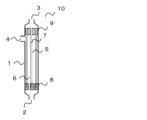
- FIG. 1 is a schematic diagram showing one embodiment of the hollow fiber membrane module of the present invention.
- FIG. 2 is a schematic flow diagram showing one form of a membrane filtration unit to which cross-flow filtration is applied.
- FIG. 3 is a schematic diagram showing a model for simulating the pressure distribution within the hollow fiber membrane module.
- FIG. 4 is a schematic flow diagram showing one form of viscosity measurement using a capillary viscometer.
- FIG. 5 is a schematic flow diagram showing one form of a membrane filtration unit for verifying simulation.
- FIG. 1 is a schematic diagram showing one embodiment of the hollow fiber membrane module of the present invention.
- directions such as “up” and “down” in this specification are based on the states shown in the drawings and are for convenience.
- the undiluted solution introduction port 2 side will be described as the downward direction.
- a container 1 having an undiluted solution inlet 2, a filtrate outlet 3, and an undiluted solution outlet 4 is filled with hollow fiber membranes 5. Both ends of the hollow fiber membrane 5 are embedded in the first potting portion 8 and the second potting portion 9 , and the first potting portion 8 and the second potting portion 9 are fixed to the container 1 . The lower end of the hollow fiber membrane 5 embedded in the first potting portion 8 is sealed. Also, the first potting part 8 has a plurality of through-holes for passing the stock solution introduced from the stock solution introduction port 2 . On the other hand, the upper end portion of the hollow fiber membrane 5 embedded in the second potting portion 9 is embedded in an open state.
- the undiluted solution inlet 2, the filtrate outlet 3, and the undiluted solution outlet 4 are cylindrical nozzles that connect the container 1 and a pipe (not shown), and are also fixed to the cylindrical container 1 in an open state. .
- the raw liquid inlet 2 is connected to the lower end of the container 1, and the filtrate outlet 3 is connected to the upper end.
- the stock solution outlet 4 is connected to the side surface of the container 1 and provided near the second potting portion 9 . Both resin and metal can be used for these materials.
- the hollow fiber membrane 5 filled in the container 1 is a hollow fibrous membrane having a liquid separation function.
- the hollow fiber membranes 5 are filled so that the axial direction of the container 1 and the axial direction of the hollow fiber membranes 5 are parallel.
- the axial direction means the longitudinal direction of the container 1 and the longitudinal direction of the hollow fiber membranes 5 .
- the first potting part 8 and the second potting part 9, in which a plurality of hollow fiber membranes are fixed with an adhesive, are potted mainly with a potting resin in which the gaps between the bundled hollow fibers are a so-called adhesive. It refers to the part filled with the agent.
- the potting part is preferably formed at the end of the hollow fiber membrane bundle.
- the potting resin which is the main component of the potting agent, epoxy resin, polyurethane resin, or silicone resin, which is excellent in adhesion to the hollow fiber membrane, heat resistance, and chemical durability, is preferable.
- the potting agent may contain additives such as silica, talc, mica, clay, calcium carbonate, glass, rubber, etc., in addition to the potting resin.
- the first potting part 8 is formed at the end of the hollow fiber membrane 5 on the undiluted solution inlet side. It is preferable that the end of the hollow fiber membrane 5 on the undiluted solution inlet side is sealed. By sealing the undiluted solution inlet side end, the filtrate flowing through the hollow portion becomes unidirectional, and on the filtrate side of the hollow fiber membrane 5, the undiluted solution inlet side end and the filtrate outlet side end are separated. can create a pressure difference between
- “sealed” means a state in which the liquid flowing inside the hollow fiber membrane 5 is not led out from the sealed end.
- the first potting part 8 is fixed to the container 1, and has a plurality of through holes for passing the stock solution introduced from the stock solution introduction port 2.
- the stock solution is introduced into the hollow fiber membrane 5 through the through holes. be done.
- the shape and number of the through-holes are not specified, and they are appropriately provided in order to suppress the occurrence of resistance and flow unevenness according to the flow rate of the stock solution to be passed.
- the first potting part 8 only needs to be positionally fixed so that the first potting part 8 does not float due to the flow of the stock solution, and may be adhesively fixed to the container 1 or may have a removable cartridge structure.
- the position fixing method is not particularly specified, and a structure for fixing the position between the container 1 and the first potting part 8 or a structure for fixing the position between the second potting part 9 and the first potting part 8 can be appropriately selected.
- the first potting part 8 is not essential if the ends of the hollow fiber membranes 5 on the side of the undiluted solution inlet are sealed. It may be a free end that is not fixed. A free end is a state in which the hollow fiber membranes are not fixed to each other with a potting agent and are freely movable.
- a method for sealing the end portion of the hollow fiber membrane 5 on the side of the undiluted solution introduction port there is a method of injecting a potting agent into the hollow portion of the hollow fiber membrane 5 for sealing, or a method of sealing the end portion by heat welding. A sealing method or the like can be applied.
- the second potting part 9 is formed at the end of the hollow fiber membrane 5 on the side of the filtrate outlet, and is fixed with the end of the hollow fiber membrane 5 on the side of the filtrate outlet being open.
- the open state means a state in which the liquid flowing inside the hollow fiber membrane is led out from the open end.
- the second potting part 9 is fixed to the container 1, but if the undiluted solution and the filtrate can be liquid-tightly separated, the second potting part 9 and the container 1 can be adhesively fixed, or a hollow container such as a so-called cartridge type can be used. A structure in which the thread membrane can be attached and detached may be employed. In the case of a cartridge type, the second potting part 9 and the container 1 may be connected via an O-ring or the like.
- the inside of the container 1 is divided into the undiluted liquid side space 6 filled with the undiluted liquid and the filtrate filled with the filtrate by the hollow fiber membranes 5 and the second potting section 9 . It is separated into side spaces 7, the undiluted solution side space 6 is a space with which the outer surface of the hollow fiber membrane 5 is in contact, and the filtrate side space 7 is a space with which the inner surface of the hollow fiber membrane 5 is in contact.
- the present invention is applied to a so-called external pressure type hollow fiber membrane module in which the raw liquid inlet 2 and the raw liquid outlet 4 are connected to the raw liquid side space 6, and the filtrate outlet 3 is connected to the filtrate side space 7. .
- Fig. 2 is a flow diagram of the membrane filtration unit.
- the stock solution is supplied from the stock solution tank 12 to the container 1 by the supply pump 14 .
- the concentrate introduced into the container 1 from the concentrate inlet 2 passes through the through hole of the first potting part 8 shown in FIG. be done. After that, it is discharged from the container 1 through the undiluted solution outlet 4 .
- This operation method is particularly suitable for filtering a stock solution containing a large amount of clogging components that accumulate on the membrane surface.
- the filtrate flow rate observed by the filtrate flow meter 32 is constant.
- the average value of the undiluted liquid introduction pressure P1 and the undiluted liquid outlet pressure P2 observed by the undiluted liquid introduction pressure gauge 41 and the undiluted liquid outlet pressure gauge 42, and the filtrate outlet pressure P3 observed by the filtrate outlet pressure gauge 43 are used. is called an average transmembrane pressure difference, and the operation is continued until the average transmembrane pressure difference reaches a predetermined pressure.
- the filtrate-side space 7 Pressure loss becomes smaller than pressure loss in the undiluted solution side space 6 .
- the raw liquid side pressure tends to be high, the filtrate side pressure to be low, and the transmembrane pressure difference at that location to be large. Therefore, the end of the hollow fiber membrane 5 on the side of the raw liquid inlet filters an excessive amount of liquid compared to the end on the side of the filtrate outlet, which is a factor in promoting fouling.
- the filtration step when performing cross-flow filtration by supplying the stock solution to the outer surface side of the hollow fiber membrane, the viscosity ⁇ f of the stock solution and the viscosity of the filtrate
- the ratio of ⁇ p is ⁇ f / ⁇ p ⁇ 1.5
- the flow rate ratio of the flow rate v f of the undiluted solution and the flow rate v p of the filtrate is 0.02 ⁇ v p /v f ⁇ 0.3.
- the pressure in the filtrate side space 7 Although the loss is smaller than the pressure loss in the undiluted solution side space 6, the flow velocity ratio between the undiluted solution flow velocity vf and the filtrate flow velocity vp (ratio of the filtrate flow velocity vp to the undiluted liquid flow velocity vf ) is set to 0.
- the required filtrate flow rate can be secured and the filtration cost can be suppressed, while the pressure loss on the undiluted solution side and the filtrate side can be homogenized, and fouling can be prevented. Progress can be suppressed.
- v p /v f ⁇ 0.3 it is possible to suppress the circulating flow rate of the stock solution from becoming excessively smaller than the flow rate of the filtrate, so that the membrane clogging component derived from the stock solution accumulates on the membrane surface.
- the required stock flow can be ensured to prevent overheating. As a result, progress of fouling can be prevented.
- the flow rate vf of the concentrate is calculated by dividing the flow rate Qc of the concentrate measured by the concentrate flowmeter 31 by the flow area Sf of the concentrate-side space 6 of the hollow fiber membrane module 10.
- FIG. The channel area Sf of the undiluted solution side space is a value obtained by subtracting the total cross-sectional area of the hollow fiber membranes 5 inserted into the container 1 from the cross-sectional area of the container 1 . Assuming that the inner diameter of the container 1 is D c , the outer diameter of the hollow fiber membranes 5 is D o , and the number of hollow fiber membranes 5 is N, the calculation is performed by the following formula (1).
- the flow velocity vp of the filtrate is calculated by dividing the flow rate Qp of the filtrate measured by the filtrate flowmeter 32 by the flow area Sp of the space 7 on the filtrate side.
- the passage area Sp of the filtrate-side space 7 is calculated by the following formula (2), where D i is the inner diameter of the hollow fiber membrane 5 .
- a feed liquid flow meter may be provided between the raw liquid inlet 2 and the feed pump 14, and the measured feed liquid flow rate Qf may be used. Also in this case, the flow velocity vf of the undiluted solution is similarly calculated.
- the values of the viscosity ⁇ f of the undiluted solution and the viscosity ⁇ p of the filtrate vary greatly depending on the temperature, it is preferable to measure the viscosity at the undiluted solution temperature measured by the undiluted solution thermometer 51 . Furthermore, since the viscosity may change due to shear caused by the flow of the undiluted solution or the filtrate, it is preferable to measure the viscosity when a shear rate ⁇ due to the flow during operation is applied.
- the shear rate ⁇ is simply calculated by the following formula (3) from the flow velocity v and the channel diameter D e .
- the channel diameter D e of the filtrate-side space 7 is the inner diameter D i of the hollow fiber membrane 5 .
- the equivalent diameter calculated by the following formula (4) is taken as the channel diameter D e .
- the viscosity measurement method a capillary viscometer is used, and the viscosity measured at the same temperature and shear rate as in actual operation is defined as the viscosity in the present invention. That is , the viscosity ⁇ is a method of measuring Using the above formula (3), the flow velocity vv in the narrow tube is set so that the shear rate in the actual operation and the shear rate in the narrow tube viscometer are the same, and the viscosity is measured.
- the thin tube viscometer there is no particular limitation as long as it can control the temperature of the tube and measure the pressure at the tube inlet and outlet, and both commercially available and self-made devices can be used.
- the ratio of the viscosity ⁇ f of the undiluted solution to the viscosity ⁇ p of the filtrate at least at the beginning of the operation is ⁇ f / ⁇ p ⁇ 1.5.
- the initial stage of operation refers to the timing when the undiluted solution is introduced into a new hollow fiber membrane module and filtration is started for the first time. is the timing to introduce and start filtration.
- the flow rate ratio between the flow rate v f of the undiluted solution and the flow rate v p of the filtrate is 0.02 ⁇ v p /v f ⁇ 0.3. , is preferable from the viewpoint of suppressing the progress of clogging.
- the flow velocity v f of the undiluted solution is preferably 0.30 m/s ⁇ v f ⁇ 1.80 m/s.
- v f ⁇ 0.30 m/s the accumulation of turbidity on the surface of the hollow fiber membrane due to the action of the stock solution flow can be suppressed, and the progress of fouling can be suppressed.
- v f ⁇ 1.80 m/s the pressure loss in the concentrate side space 6 can be suppressed, so that the concentrate side pressure applied to the end of the hollow fiber membrane 5 on the concentrate inlet side can be suppressed.
- the flow velocity v f of the stock solution is preferably 0.50 m/s ⁇ v f ⁇ 1.50 m/s, more preferably 0.70 m/s ⁇ v f ⁇ 1.30 m/s.
- the flow velocity v p of the filtrate is preferably 0.006 m/s ⁇ v p ⁇ 0.30 m/s.
- v p ⁇ 0.006 m/s the pressure loss in the filtrate side space 7 can be increased, and the pressure loss difference with the concentrate side space 6 can be reduced. Furthermore, since the filtration flux itself can be increased, the required number of membrane modules can be reduced.
- v p ⁇ 0.30 m/s the pressure loss in the filtrate side space 7 can be prevented from becoming excessively high, and the pressure loss difference with the undiluted liquid side space 6 can be reduced.
- the flow velocity v p of the filtrate is preferably 0.01 m/s ⁇ v p ⁇ 0.25 m/s, more preferably 0.03 m/s ⁇ v p ⁇ 0.20 m/s.
- the ratio of the flow velocity vf of the undiluted solution to the flow velocity vp of the filtrate is 0.02 ⁇ vp / vf ⁇ 0.3 during the entire period of the cross-flow filtration operation of the undiluted solution using the hollow fiber membrane module.
- the raw liquid flow rate v f and the filtrate flow rate v p can be controlled by adjusting the feed pump 14 , the concentrated liquid valve 21 and the filtrate valve 22 .
- the flow rate vf of the undiluted solution can be adjusted by the rotation speed of the supply pump 14 and the concentrated solution valve 21 .
- the flow velocity vp of the filtrate is affected by the transmembrane pressure difference and the flow velocity of the stock solution. Since the transmembrane pressure is the pressure difference between the raw liquid side space 6 and the filtrate side space 7, it can be controlled by adjusting the rotation speed of the supply pump 14 and the opening degrees of the concentrated liquid valve 21 and the filtrate valve 22. is.
- PID control Proportional-Integral-Differential control
- the method for operating a hollow fiber membrane module of the present invention is preferably applied to a stock solution having a viscosity ⁇ f of 3.0 mPa ⁇ s or more.
- the viscosity of the filtrate is about 1.0 mPa s. Therefore, with a stock solution of 3.0 mPa s or more, a difference from the viscosity ⁇ p of the filtrate occurs, and the effect of the operation method of the present invention is becomes more likely to occur.
- the viscosity ⁇ f of the concentrate is too high, the pressure loss in the concentrate side space 6 will increase and the operation will become difficult. It is preferably applied to a stock solution of 30.0 mPa ⁇ s or less, more preferably to a stock solution of 10.0 mPa ⁇ s or less.
- the stock solution to which the hollow fiber membrane module operation method of the present invention is applied there are no particular restrictions on the stock solution to which the hollow fiber membrane module operation method of the present invention is applied, and various stock solutions having a ratio ⁇ f / ⁇ p of the viscosity ⁇ f of the stock solution to the viscosity ⁇ p of the filtrate of 1.5 or more.
- the dissolved organic carbon (DOC) concentration is preferably 1,000 mg/L or more and 100,000 mg/L or less.
- the DOC concentration is 1,000 mg/L or more
- the stock solution contains a large amount of thickening components and is highly effective in suppressing the progress of fouling by applying the method for operating the hollow fiber membrane module of the present invention. It is preferably applied to stock solutions having a DOC concentration of 5,000 mg/L or more, more preferably 10,000 mg/L or more.
- the DOC concentration is obtained by measuring the total organic carbon (TOC) concentration of the liquid filtered through a membrane filter with a pore size of 0.45 ⁇ m.
- the TOC concentration is calculated by the TC-IC method, which is calculated by subtracting the inorganic carbon (IC) from the total carbon (TC), or by adding acid to the sample, aerating it, and measuring the total carbon in the liquid after aeration. It can be measured using the NPOC method or the like.
- the TC-IC method is calculated by subtracting the inorganic carbon (IC) from the total carbon (TC), or by adding acid to the sample, aerating it, and measuring the total carbon in the liquid after aeration. It can be measured using the NPOC method or the like.
- the TC-IC method is preferable to use the TC-IC method for measurement.
- the hollow fiber membranes 5 mounted in the hollow fiber membrane module of the present invention especially if separation can be performed so that the ratio ⁇ f / ⁇ p between the viscosity ⁇ f of the undiluted solution and the viscosity ⁇ p of the filtrate is 1.5 or more It is not limited and can be applied to various membranes such as microfiltration membranes, ultrafiltration membranes, nanofiltration membranes, reverse osmosis membranes, etc. from those with large pore sizes.
- the pressure loss when the undiluted solution permeates the membrane is much larger than the pressure loss caused by the liquid flow, and the effect of the pressure loss in the undiluted solution side space 6 and the filtrate side space 7 is small. It is preferred to apply a filtration membrane.
- the thickening component that increases the viscosity of the stock solution is often a high molecular weight component dissolved in the stock solution, it is possible to apply an ultrafiltration membrane that can separate the dissolved high molecular weight component. preferable.
- microfiltration membranes and ultrafiltration membranes there are various definitions for microfiltration membranes and ultrafiltration membranes, but they are defined as follows in the present invention. That is, a separation membrane with a pore size of 0.1 ⁇ m or more and 10 ⁇ m or less is defined as a microfiltration membrane, a separation membrane with a pore size smaller than 0.1 ⁇ m and a molecular weight cutoff of 1,000 Da or more is defined as an ultrafiltration membrane, and a molecular weight cutoff of 1,000 Da or more is defined as an ultrafiltration membrane. Separation membranes smaller than 000 Da are called nanofiltration membranes and reverse osmosis membranes.
- the hollow fiber membrane 5 used in the present invention preferably has a strength (load at break) of 500 gf/thread or more.
- a strength (load at break) of 500 gf/thread or more 500 gf/thread or more.
- FIG. 1 shows that after introducing the undiluted liquid into the hollow fiber membrane module 10 from the undiluted liquid inlet 2 of the hollow fiber membrane module 10, it is discharged from the undiluted liquid outlet 4.
- the stock solution flow is turned by 90° when it is discharged from the outlet 4 . Therefore, a shearing force perpendicular to the longitudinal direction of the hollow fiber membrane 5 is applied to the hollow fiber membrane 5 near the undiluted solution outlet 4 .
- the strength of the hollow fiber membranes 5 of 500 gf/membrane or more makes it possible to suppress fiber breakage, membrane damage, etc. against shear caused by the cross-flow velocity assumed in the present application.
- the strength is the load (gf) applied when the hollow fiber membrane 5 is stretched in the axial direction by a tensile tester or the like and is broken.
- the measured temperature at this time is the stock solution temperature during actual operation.
- the strength of the hollow fiber membrane 5 is preferably 600 gf/line or more, more preferably 700 gf/line or more.
- the strength measurement method is not particularly limited, but for example, using a tensile tester that can control the atmospheric temperature, pull a sample with a measurement length of 50 mm at a tensile speed of 50 mm / min, and change the sample 5 times or more. It can be measured by performing and calculating the average value of the breaking strength.
- the flow rate v f of the stock solution and the viscosity ⁇ f of the stock solution satisfy the relationship v f ⁇ 0.135 ⁇ f +3.0.
- the flow velocity vf of the undiluted solution is a value calculated by Equation 1, and its unit is m/s.
- the viscosity ⁇ f of the stock solution is the viscosity at the actual operating temperature, and the unit is mPa ⁇ s.
- the outer diameter Do is preferably 600 ⁇ m ⁇ D 0 ⁇ 2000 ⁇ m.
- D o ⁇ 2000 ⁇ m the membrane area per hollow fiber membrane module does not become excessively small, and the filtrate flow rate per module can be ensured.
- D o ⁇ 600 ⁇ m it is possible to suppress an excessive increase in pressure loss in the space on the side of the concentrate due to an increase in the contact area between the concentrate and the hollow fiber membrane.
- the outer diameter Do is preferably 900 ⁇ m ⁇ D 0 ⁇ 1800 ⁇ m, more preferably 1000 ⁇ m ⁇ D 0 ⁇ 1500 ⁇ m.
- the inner diameter D i of the hollow fiber membrane 5 is preferably 300 ⁇ m ⁇ D i ⁇ 1000 ⁇ m.
- the pressure loss in the filtrate-side space 7 can be controlled within an appropriate range, and the transmembrane pressure difference in the longitudinal direction of the hollow fiber membrane 5 can be reduced.
- 400 ⁇ m ⁇ D i ⁇ 900 ⁇ m is preferred, and 500 ⁇ m ⁇ D i ⁇ 800 ⁇ m is more preferred.
- the outer diameter D o and the inner diameter D i of the hollow fiber membrane 5 are obtained by cutting the hollow fiber membrane 5 with a single blade or the like along a plane perpendicular to the axial direction and observing the cross section with a microscope or the like. to measure. If the outer or inner circle is flattened, measure the length of the longest diameter (major diameter) and the shortest diameter (minor diameter), and calculate by averaging both. .
- the hollow fiber membranes 5 loaded in the hollow fiber membrane module 10 are arbitrarily cut, and the values obtained by averaging the outer diameter and inner diameter of 10 or more hollow fiber membranes are preferably used.
- the filling rate M of the hollow fiber membranes 5 loaded in the hollow fiber membrane module 10 is preferably 25% ⁇ M ⁇ 45%. By satisfying 25% ⁇ M ⁇ 45%, it is possible to control the pressure loss on the undiluted solution side within an appropriate range while ensuring the membrane area per module.
- the filling rate M is preferably 28% ⁇ M ⁇ 42%, more preferably 30% ⁇ M ⁇ 40%.
- the filling rate M is calculated from the inner diameter D c of the container 1, the outer diameter D o of the hollow fiber membranes 5, and the number N of the hollow fiber membranes 5 by the following formula (6). If there is a member other than the hollow fiber membrane 5 existing in the concentrate side space 6 in the container 1, the cross-sectional area of that member perpendicular to the axial direction of the container 1 is calculated, and the exclusive area S of the hollow fiber membrane 5 is calculated. Calculate in addition to p .
- the membrane length L is the portion of the hollow fiber membrane 5 that is actually used for filtration when the hollow fiber membrane 5 is filled in the container 1, that is, the portion that the outer surface of the hollow fiber membrane 5 is in contact with the stock solution. is the length of In FIG. 1, it is the length of the hollow fiber membrane 5 from the end face of the first potting part 8 on the second potting part side to the end face of the second potting part 9 on the first potting part side.
- the length of the hollow fiber membranes embedded in the first potting portion 8 and the second potting portion 9 is not considered here.
- the film length L is preferably 0.50 m ⁇ L ⁇ 2.00 m.
- the film length L is preferably 0.70 m ⁇ L ⁇ 1.50 m, more preferably 0.80 m ⁇ L ⁇ 1.20 m.
- the membrane length L is actually used for filtration.
- half of the length of the hollow fiber membrane to be treated that is, half of the length of the fiber at the portion where the outer surface of the hollow fiber membrane is in contact with the stock solution.
- the portion of the free end that is not subjected to the adhesive or heat sealing treatment is connected to the first potting portion 8 .
- 2 is the length up to the end face of the potting portion 9 on the undiluted solution inlet side.
- the membrane length L is the portion of the hollow fiber membrane that is actually used for filtration, that is, the portion where the outer surface of the hollow fiber membrane comes into contact with the stock solution. , may be measured as the length in the direction parallel to the container 1 .
- the method for operating a hollow fiber membrane module of the present invention in addition to the above-described filtration step, preferably further includes a backwash step in which a washing liquid is caused to flow from the inner surface side to the outer surface side of the hollow fiber membranes.
- the surface pore diameter ⁇ o of the outer surface of the hollow fiber membrane is 0.005 ⁇ m ⁇ ⁇ o ⁇ 0.02 ⁇ m, and the ratio of the surface pore diameter ⁇ i of the inner surface of the hollow fiber membrane to the surface pore diameter ⁇ o of the outer surface is Preferably, ⁇ i / ⁇ o >50.
- components larger than the pores on the surface of the hollow fiber membrane are deposited on the surface of the hollow fiber membrane 5.
- components contained in the undiluted solution that are smaller than the pores on the surface of the hollow fiber membrane enter into the pores. This causes clogging on the membrane surface and inside the membrane.
- components deposited on the membrane surface are removed by the flow generated by the cross-flow filtration operation.
- a backwashing step in which the cleaning liquid is passed from the inner surface side toward the outer surface side of the hollow fiber membrane.
- the backflow washing step for example, using a compressed gas, a pump, or the like from the filtrate tank 13, the washing liquid is passed through the filtrate-side space 7 of the hollow fiber membrane module 10, and the washing liquid flowing out to the undiluted liquid-side space 6 is passed through the hollow It is a step of discharging to the outside of the fiber membrane module 10 .
- clogging components in the stock solution are held in the space on the side of the stock solution by the hollow fiber membrane, and adhere to the membrane surface. , clogging components tend to accumulate in the pores near the surface.
- the surface pore diameter ⁇ o of the outer surface of the hollow fiber membrane is preferably 0.005 ⁇ m ⁇ ⁇ 0 ⁇ 0.02 ⁇ m.
- the pore diameter ⁇ o is more preferably 0.005 ⁇ m ⁇ ⁇ 0 ⁇ 0.009 ⁇ m, and particularly preferably 0.005 ⁇ m ⁇ ⁇ 0 ⁇ 0.008 ⁇ m.
- the surface pore size in the present invention is obtained by the following method. Images of the outer and inner surfaces of the hollow fiber membrane observed with a scanning electron microscope (SEM) or a transmission electron microscope (TEM) are binarized using free software "ImageJ". When binarizing, after creating a background with 1 pixel in Subtract Background, select the condition: RenyiEntropy in Threshold (threshold for binarization). In the obtained binarized image, by selecting Area in Analyze Particles, the area of each hole is obtained, and the diameter is calculated assuming that each hole is a circle. The surface pore diameter is determined by averaging the pore diameters of 100 or more pores.
- the surface pore diameter may be obtained from the cross-sectional pore diameter described later.
- the surface pore size is defined as the cross-sectional pore size at a depth of 20 ⁇ m or less from the surface.
- the ratio of the pore diameter ⁇ i of the inner surface of the hollow fiber membrane, which is the surface in contact with the filtrate, to the pore diameter of the outer surface ⁇ o , which is the surface of the hollow fiber membrane in contact with the stock solution (the ratio of the pore diameter ⁇ i of the inner surface to the pore diameter of the outer surface ⁇ o
- the ratio ⁇ i / ⁇ o is preferably ⁇ i / ⁇ o >50.
- ⁇ i / ⁇ o >60 is preferred, and ⁇ i / ⁇ o >70 is particularly preferred.
- the cleaning liquid used in the backwash process it is preferable to use a liquid with a lower viscosity than the stock solution, such as pure water or filtrate, as this will facilitate the cleaning effect.
- the backwashing process can be performed during the operation of the cross-flow filtration, after the operation is stopped, etc., and the frequency thereof may be appropriately set according to the conditions during the operation.
- the hollow fiber membrane 5 of the present invention may be a single-layer hollow fiber membrane, but a composite hollow fiber membrane in which two or more layers are laminated is preferable because ⁇ i / ⁇ o can be easily obtained.
- Lp i ⁇ Lp o between the transmission coefficient Lp o of the layer on the outer surface side and the transmission coefficient Lp i of the layer on the inner surface side.
- the permeability coefficient Lp is an index of ease of passage of water, and is represented by the following formula (7).
- Formula (7) is described, for example, in Journal of Chemical Engineering of Japan (Vol. 15, No. 3 (1982) pp. 200-205).
- the cross-sectional pore size is indicated by the radius instead of the diameter, and the porosity is indicated by the open area ratio, but they are used in the same meaning.
- the pure water permeability K which will be described later, is an index of the ease with which water can pass, like the permeability coefficient Lp. The difference is that Lp is calculated from the microstructure of the separation membrane. The permeability coefficient Lp is only used to compare the water permeability in each layer.
- ⁇ is the cross-sectional pore diameter ( ⁇ m)
- A is the porosity (-)
- ⁇ is the viscosity of water (Pa ⁇ s)
- H is the thickness ( ⁇ m).
- the permeability coefficient Lp i of the layer on the inner surface side is larger than the permeability coefficient Lp o of the layer on the outer surface side, the pressure loss of the cleaning liquid passing through the layer on the inner surface side can be reduced during backwashing. It is possible to increase the pressure acting on the layer on the outer surface side where clogging components tend to accumulate, thereby enhancing the cleaning effect.
- the cross-sectional pore size of the present invention can be obtained by the following method.
- the cross-sectional sample for observation is a hollow fiber membrane embedded using a commercially available embedding agent for preparing frozen tissue sections, and a cryo-ultramicrotome is used to take a section of the porous membrane at a low temperature with a thickness of 100 nm. It is obtained by vacuum drying overnight.
- a cross section of the hollow fiber membrane is observed with a scanning electron microscope (SEM) or a transmission electron microscope (TEM) to obtain an image of each layer. If the layer structure is symmetrical in the film thickness direction, an image of the central part of the layer is obtained. get. After that, it is binarized using free software "ImageJ".
- Threshold for binarization.
- the area of each hole is obtained, and the diameter is calculated assuming that each hole is a circle.
- the cross-sectional pore size is obtained by averaging the pore sizes of 100 or more pores.
- the porosity A can also be obtained from the binarized image of the cross section of the hollow fiber membrane described above. Calculate the rate.
- the permeability coefficient Lp is calculated at intervals of 10 ⁇ m in the film thickness direction, and the values calculated at intervals of 10 ⁇ m are used for the cross-sectional pore diameter and the gap. Further, when the structure of each layer is symmetrical in the film thickness direction, the transmission coefficient Lp calculated in the region located at the center of each layer in the film thickness direction is set as the Lp of the layer, and the structure of each layer is the film thickness. In the case of asymmetry in the thickness direction, the permeability coefficient Lp calculated in the region where the cross-sectional pore diameter is the densest in the thickness direction is taken as the Lp of the layer.
- the thickness H o of the layer with a small transmission coefficient on the outer surface side and the thickness H i of the layer with a large transmission coefficient on the inner surface side satisfy H o /H i ⁇ 1.0.
- H o /H i ⁇ 1.0 pressure loss occurring in a layer with a small permeability coefficient can be reduced.
- H o / H i is too small , the separation function for blocking the thickening component is lowered . ⁇ 0.4 is more preferred.
- the composite hollow fiber membrane composed of two layers preferably has a spherical structure layer on the inner surface side and a three-dimensional network structure layer on the outer surface side.
- the thickness of the three-dimensional network structure layer depends on the above-described cleaning effect and the thickening component. from the viewpoint of the blocking property, the thickness is preferably 20 ⁇ m or more and 120 ⁇ m or less, more preferably 30 ⁇ m or more and 80 ⁇ m or less. If the thickness of the three-dimensional network structure layer is less than 20 ⁇ m, the rejection rate of the thickening component may decrease. When the thickness is more than 120 ⁇ m, the permeation resistance becomes too large, which may cause a decrease in cleaning effect and a decrease in water permeability.
- the thickness of the spherical structure layer is also preferably 120 ⁇ m or more and 500 ⁇ m or less, more preferably 200 ⁇ m or more and 300 ⁇ m or less, from the viewpoint of the washing effect described above and the strength and water permeability of the hollow fiber membrane.
- a liquid-liquid thermally induced phase separation method or a non-solvent induced phase separation method, which will be described later, can be used to form the three-dimensional network structure layer, and a solid-liquid thermally induced phase separation method can be used to form the spherical structure layer. can be used.
- polymer material for the hollow fiber membrane 5 examples include polyethylene, ethylene-propylene copolymer, ethylene-ethyl acrylate copolymer, ethylene-vinyl acetate copolymer, ionomer, polypropylene, and poly-4-methyl.
- Olefin-based polymers such as pentene-1, fluorine-containing polymers such as polytetrafluoroethylene, polychlorotrifluoroethylene, polyvinylidene fluoride, tetrafluoroethylene-ethylene copolymers or tetrafluoroethylene-perfluoroalkyl vinyl ether copolymers , cellulose-based polymers such as cellulose acetate, polyvinyl chloride, acrylonitrile-based polymers, silicone-based polymers, polyamides, polyimides, polyethersulfones, polysulfones, polyphenylene oxides, polyphenylene sulfides, polyarylates, polyetheretherketones, polyetherimides, polycarbonates Or a polyvinyl alcohol-based polymer may be mentioned.
- fluorine-containing polymers such as polytetrafluoroethylene, polychlorotrifluoroethylene, polyvinylidene fluoride, tetrafluoroethylene
- a fluororesin-based polymer, polyethersulfone or polysulfone is preferable in order to increase the heat resistance, physical strength and chemical durability of the resulting hollow fiber membrane, but the hollow fiber membrane module for cross-flow filtration imposes a large load on the membrane.
- fluororesin-based polymers having excellent strength are preferred.
- a hydrophilic polymer may be included in order to reduce fouling of the hollow fiber membrane 5.
- specific examples include polymers containing vinyl alcohol, ethylene glycol, vinylpyrrolidone, methacrylic acid, allyl alcohol, cellulose, and vinyl acetate.
- the copolymer containing a hydrophilic group includes polyvinyl alcohol having a saponification degree of less than 99%, a vinylpyrrolidone/vinyl acetate copolymer, a vinylpyrrolidone/vinylcaprolactam copolymer, and a vinylpyrrolidone/vinyl alcohol copolymer. polymerization polymer, and the like.
- Method for producing hollow fiber membrane As an example of the method for producing a hollow fiber membrane according to the present invention, a method for producing a hollow fiber membrane using a fluororesin-based polymer will be described. Various methods such as a thermally induced phase separation method and a non-solvent induced phase separation method can be used as a method for producing a hollow fiber membrane using a fluororesin polymer. A manufacturing method using a thermally induced phase separation method is shown below.
- a fluororesin-based polymer solution that is, containing the fluororesin-based polymer Prepare the membrane-forming stock solution.
- a high-strength porous hollow fiber membrane can be obtained when the polymer concentration in the membrane-forming stock solution is high.
- the concentration of the fluororesin polymer is preferably 20% by weight or more and 60% by weight or less, more preferably 30% by weight or more and 50% by weight or less.
- the term "poor solvent” means that a fluororesin polymer cannot be dissolved at a low temperature of 60° C. or lower by 5% by weight or more, but is 60° C. or higher and the melting point of the fluororesin polymer It is a solvent capable of dissolving 5% by weight or more in a high temperature range of about 178° C. when the molecule is composed of vinylidene fluoride homopolymer alone.
- a good solvent is a solvent capable of dissolving 5% by weight or more of a fluororesin-based polymer even in a low temperature range of less than 60°C. It is defined as a solvent that neither dissolves nor swells the resinous polymer.
- cyclohexanone, isophorone, ⁇ -butyrolactone, methyl isoamyl ketone, propylene carbonate, dimethyl sulfoxide, etc., and mixed solvents thereof can be mentioned as poor solvents for fluororesin-based polymers.
- Good solvents include N-methyl-2-pyrrolidone, dimethylacetamide, dimethylformamide, methyl ethyl ketone, acetone, tetrahydrofuran, tetramethyl urea, trimethyl phosphate and mixed solvents thereof.
- Non-solvents include water, hexane, pentane, benzene, toluene, methanol, ethanol, carbon tetrachloride, o-dichlorobenzene, trichloroethylene, ethylene glycol, diethylene glycol, triethylene glycol, propylene glycol, butylene glycol, pentanediol, Aliphatic hydrocarbons such as hexanediol, low molecular weight polyethylene glycol, aromatic hydrocarbons, aliphatic polyhydric alcohols, aromatic polyhydric alcohols, chlorinated hydrocarbons, or other chlorinated organic liquids and their mixed solvents, etc. is mentioned.
- thermally induced phase separation methods that induces phase separation by temperature change is used to obtain a hollow fiber membrane from a membrane-forming stock solution containing a fluororesin-based polymer.
- Thermally induced phase separation methods mainly utilize two types of phase separation mechanisms.
- One is a liquid-liquid phase in which a polymer solution that is homogeneously dissolved at high temperature separates into a polymer-rich phase and a polymer-dilute phase due to the decrease in dissolving ability of the solution when the temperature is lowered, and then the structure is fixed by crystallization. Separation method.
- the other is a solid-liquid phase separation method in which a polymer solution uniformly dissolved at a high temperature is phase-separated into a polymer solid phase and a solvent phase due to crystallization of the polymer when the temperature is lowered.
- the former method mainly forms a three-dimensional network structure
- the latter method forms a spherical structure mainly composed of spherical tissue.
- the latter phase separation mechanism is preferably used as a hollow fiber membrane for cross-flow filtration, which requires strength.
- polymer concentrations and solvents are selected that induce solid-liquid phase separation.
- the hollow portion-forming liquid is discharged from the inner tube of the double-tube type spinneret.
- Dispense. A porous hollow fiber membrane is obtained by cooling and solidifying the membrane-forming undiluted solution thus discharged in a cooling bath.
- the cooling bath for cooling the fluororesin-based polymer solution discharged from the die will be described.
- the cooling bath it is preferable to use a mixed liquid containing a poor solvent or a good solvent with a concentration of 50 to 95% by weight and a non-solvent with a concentration of 5 to 50% by weight.
- the same poor solvent as the polymer solution as the poor solvent.
- the cooling bath it is preferable to use a mixed liquid composed of a poor solvent or a good solvent with a concentration of 50 to 95% by weight and a non-solvent with a concentration of 5 to 50% by weight.
- the same poor solvent as the polymer solution as the poor solvent.
- a hollow fiber membrane comprising a fluororesin-based polymer obtained by the above method may be stretched. The stretching ratio and stretching temperature are appropriately selected depending on the desired pore diameter, size and pure water permeability.
- the inner and outer diameters of the hollow fiber membranes are adjusted mainly by adjusting the diameter of the double-tube spinneret and the discharge rate of the undiluted membrane-forming solution and the hollow portion-forming liquid.
- the dimensions can also be adjusted by changing the draw ratio and draw temperature.
- a method of obtaining a composite hollow fiber membrane there are a method of forming multiple layers simultaneously and a method of sequentially forming other layers on a single-layer hollow fiber membrane.
- the former method for example, there is a method of composite molding a plurality of resin solutions using a multi-tube spinneret.
- a method of spray coating the solution There is a method of spray coating the solution.
- the method of applying a resin solution for forming other layers, scraping off the resin solution, and then solidifying the resin solution is simple and preferable.
- the resin solution forming the other layers is not particularly limited, but a three-dimensional network structure is preferably used for the purpose of modifying or densifying the surface of the separation membrane. be done.
- a non-solvent-induced phase separation method can be used to form the three-dimensional network structure.
- the non-solvent-induced phase separation is phase separation in which a resin solution is solidified by contact with a non-solvent.
- the solvent for the resin solution is preferably a good solvent for the resin. , methyl ethyl ketone, acetone, lower alkyl ketones such as tetrahydrofuran, esters, amides, etc. and mixed solvents thereof.
- the good solvent is a solvent capable of dissolving 5% by weight or more of the polyvinylidene fluoride resin even at a low temperature of less than 60°C.
- a non-solvent is defined as a solvent that neither dissolves nor swells the polyvinylidene fluoride resin up to the melting point of the polyvinylidene fluoride resin or the boiling point of the solvent.
- non-solvents for polyvinylidene fluoride resins include water, hexane, pentane, benzene, toluene, methanol, ethanol, carbon tetrachloride, o-dichlorobenzene, trichloroethylene, ethylene glycol, diethylene glycol, triethylene glycol, and propylene.
- Aliphatic hydrocarbons such as glycols, butylene glycols, pentanediol, hexanediol, low molecular weight polyethylene glycols, aromatic hydrocarbons, aliphatic polyhydric alcohols, aromatic polyhydric alcohols, chlorinated hydrocarbons, or other chlorinated Examples include organic liquids and mixed solvents thereof.
- the types of hollow fiber membrane modules include a container-integrated module in which the container 1 and the hollow fiber membranes 5 are fixed with an adhesive, and a container-integrated module in which the container 1 and the hollow fiber membranes 5 are not fixed with an adhesive, and the hollow fiber membranes 5 are separated from the container 1. It is divided into detachable cartridge type modules.
- a plurality of hollow fiber membranes 5 are inserted into the container 1, and the ends of the hollow fiber membranes 5 and the container 1 are fixed with an adhesive.
- the hollow fiber membranes are inserted into a special jig or the like, and the membranes are adhered to each other with an adhesive, and are not fixed to the container 1 .
- the hollow fiber membrane 5 is inserted into a fixing jig or container, or both, and an adhesive is poured into it to fix it.
- Methods for filling the gaps between the hollow fiber membranes with the adhesive include, for example, a centrifugal potting method in which the potting agent permeates using centrifugal force, or a static potting method in which the adhesive permeates by natural flow. .
- the adhesive may be injected into a casting mold to fill the gaps between the hollow fiber membranes.
- the end of the hollow fiber membrane 5 When opening the end of the hollow fiber membrane fixed with an adhesive, the end of the hollow fiber membrane 5 is sealed in advance so that the adhesive does not flow into the hollow part of the hollow fiber membrane when the adhesive is poured. and secure with adhesive.
- Sealing methods include a method of injecting an adhesive only into the hollow portion, a method of welding with heat or a solvent, and the like. After fixing the hollow fiber membranes 5 with sealed ends with an adhesive, it is possible to open the hollow fiber membranes 5 by cutting the other end side from the sealed part in the cross-sectional direction. If the ends of the hollow fiber membrane are fixed with an adhesive without being sealed, the adhesive flows into the hollow portion of the hollow fiber membrane 5, so that the ends are sealed.
- a method of fixing both ends of the hollow fiber membrane 5 with an adhesive may be adopted, but the end of the hollow fiber membrane 5 on the side of the undiluted solution inlet may be a free end that is not fixed with an adhesive. .
- FIG. 3 shows the model outline for the simulation.
- FIG. 3(a) shows one hollow fiber membrane 5 and the flow of the stock solution and the filtrate.
- the undiluted solution is indicated by a hatched arrow
- the filtrate is indicated by an open arrow.
- the end of the hollow fiber membrane 5 on the side of the undiluted solution inlet is sealed, and the end on the side of the filtrate outlet is open, so that all the filtrate is led out from the end on the side of the filtrate outlet.
- FIG. 3(a) shows one hollow fiber membrane 5 and the flow of the stock solution and the filtrate.
- the undiluted solution is indicated by a hatched arrow
- the filtrate is indicated by an open arrow.
- n is an integer of 0 or more
- k is a natural number of 1 or more.
- the filtrate drawn out from the minute section n ⁇ 1 and the filtrate filtered by the membrane in the minute section n join.
- the filtrate flow rate Q i,n derived from the minute section n the filtrate amount derived from the minute section n ⁇ 1 is Q i,n ⁇ 1
- the filtrate filtered by the membrane in the minute section n is
- the filtrate flow rate Q p,n in the minute interval n is determined by the undiluted solution side pressure P o,n and the filtrate side pressure P i,n in the minute interval n, the membrane area A n , the membrane filtration resistance R n , and the filtration temperature It is calculated from the following equations (9) to (11) from the viscosity ⁇ p of the filtrate at .
- the undiluted solution side pressure P o,n in the minute section n is calculated by the following formula (12), taking into consideration the undiluted solution introduction pressure P o,0 and the pressure loss ⁇ P 0 ⁇ l n caused by the undiluted solution flow. Since part of the stock solution is actually filtered by the membrane, the circulation flow rate varies in the axial direction of the hollow fiber membranes 5, but this can be ignored because the flow rate to be filtered is small relative to the circulation flow rate. Therefore, in this model, the pressure loss ⁇ P o per unit length in the axial direction caused by the flow of the stock solution is calculated as being constant regardless of the position.
- the pressure loss ⁇ P o per unit length is calculated from the equivalent diameter D e of the undiluted solution side space 6 and the viscosity ⁇ f of the undiluted solution using the following equations (13) and (14). Note that ⁇ is the density of the concentrate, Dc is the diameter of the inner circle of the container 1, and ⁇ is the shape correction coefficient of the concentrate-side channel.
- the filtrate side pressure P i,n in the minute section n is calculated from the pressure loss when flowing inside the hollow fiber membrane 5 .
- the Reynolds number Re i,n of the filtrate flowing inside the hollow fiber membrane 5 is calculated, and the pressure loss from the minute section n to the end on the filtrate outlet side is integrated.
- v p,n is the flow velocity of the filtrate in the minute interval n.
- the following formulas (15) and (16) show the calculation method when the flow inside is assumed to be laminar.
- the difference between the undiluted solution side pressure P o,n and P i,n in the minute section n is the transmembrane pressure ⁇ P m,n in that section.
- ⁇ P m,k ⁇ P m,0 which is the transmembrane pressure difference in the axial direction of the hollow fiber membrane 5, is 50 kPa or less.
- the pure water permeation performance K was measured by fabricating a miniature module composed of three hollow fiber membranes with a membrane length of 0.1 m. External pressure dead end filtration of reverse osmosis membrane filtered water was performed for 10 minutes under conditions of a temperature of 25° C. and a filtration differential pressure of 16 kPa to determine the permeation amount (m 3 ). The permeation amount (m 3 ) is converted into a value per unit time (h) and effective membrane area (m 2 ), and further multiplied by (50/16) to convert to a value at a pressure of 50 kPa. A permeation performance K was obtained.
- the effective membrane area is the area of the portion of the outer surface of the hollow fiber membrane 5 that is actually used for filtration.
- measuring strength Using a tensile strength tester (TENSILON (registered trademark) / RTM-100, manufactured by Toyo Baldwin Co., Ltd.), a sample with a measurement length of 50 mm is pulled in an atmosphere of 25 ° C. at a speed of 50 mm / min, and the sample is changed. Five or more tests were performed, and the average value was calculated.
- TENSILON registered trademark
- RTM-100 manufactured by Toyo Baldwin Co., Ltd.
- Viscosity was measured using the apparatus shown in FIG.
- a stock solution tank 12 and a thin tube 16 were placed in a constant temperature water bath 15 and connected with a fluorine tube so that the stock solution could be sent to and returned from the thin tube 16 .
- a fluorine tube having an inner diameter of 2.0 mm and a tube length of 1.0 m was used as the thin tube 16 .
- a tube inlet pressure gauge 45 and a tube outlet pressure gauge 46 were connected to both ends of the thin tube. Water was filled in the constant temperature water tank 15, and the temperature of the undiluted solution was adjusted to the same temperature as during actual operation.
- the shear rate is obtained from the channel diameter D e and the flow rate v of the hollow fiber membrane module used in actual operation, and the flow rate v v of the undiluted solution sent to the thin tube so that the shear rate is equivalent to the shear rate ⁇ of the actual module . It was set.
- the stock solution was fed at the set flow rate vv , and the viscosity was calculated using equation (5) from the measured tube inlet pressure P1 and tube outlet pressure P2.
- the cross-sectional pore size was measured by using a cryo-ultramicrotome (Leica; FC7) with a hollow fiber membrane embedded using a commercial embedding agent for preparing frozen tissue sections (manufactured by Tissue Tech; O.C.T. Compound).
- a 100 nm-thick slice was taken from the porous membrane in the direction perpendicular to the surface at ⁇ 40° C., and vacuum-dried overnight at room temperature.
- the cross section of the hollow fiber membrane is observed with SEM (manufactured by Hitachi High-Technologies Corporation; S-5500) or TEM (manufactured by JEOL Ltd.; JEM-1400Plus), an image is obtained, and two images are obtained using the free software "ImageJ". valued.
- an apparatus comprising a double-tube mouthpiece, a pipe connected to the mouthpiece, and two gear pumps arranged on the pipe was used.
- the raw material liquid was retained at 100 to 103° C. for 15 seconds while being pressurized to 2.5 MPa. Thereafter, while the ⁇ -butyrolactone 85% by weight aqueous solution was discharged from the inner tube of the double-tube spinneret, the raw material liquid was discharged from the outer tube.
- the raw material liquid was retained for 20 seconds in a cooling bath containing 85% by weight of ⁇ -butyrolactone aqueous solution at a temperature of 5° C. to solidify. Then, the hollow fiber membrane obtained above was stretched 1.5 times in water at 95° C. to obtain a support layer.
- a composite membrane was obtained by applying a functional layer to the support layer obtained above.
- the functional layer contains 12% by weight of a vinylidene fluoride homopolymer having a weight average molecular weight of 284,000, 7.2% by weight of cellulose acetate (Eastman Chemical Co., CA435-75S), and N-methyl-2-pyrrolidone.
- a polymer solution was prepared by mixing and dissolving at a temperature of 95° C. at a rate of 80.8% by weight.
- This membrane-forming stock solution was evenly applied to the surface of the hollow fiber membrane having a spherical structure, and immediately solidified in a coagulation bath containing 100% water to form a three-dimensional network structure layer on the spherical structure layer.
- a thread membrane was produced.
- the resulting hollow fiber membrane had an outer diameter of 1.30 mm, an inner diameter of 0.75 mm, a pure water permeability of 0.4 m/hr, and a tenacity of 1010 g/membrane.
- the pore diameter ⁇ o of the outer surface was calculated to be 0.006 ⁇ m from the binarized SEM image
- the pore diameter ⁇ i of the inner surface was calculated to be 0.6 ⁇ m from the cross-sectional pore diameter
- ⁇ i / ⁇ o was 100.
- the thickness Li of the spherical structure layer was 0.225 mm.
- Reference example 2 In Reference Example 1, the temperature of the coagulation bath for solidifying the membrane-forming stock solution for the functional layer was adjusted to produce a hollow fiber membrane having a pore diameter of 0.010 ⁇ m on the outer surface. At this time, the outer diameter was 1.30 mm, the inner diameter was 0.75 mm, the pure water permeability coefficient was 0.6 m/hr, the strength was 1010 g/wire, and ⁇ i / ⁇ o was 60.
- the polymer solution prepared from the outer tube of the double-tube type spinneret is coagulated in a 100% water coagulation bath while discharging the injection liquid made of 100% water from the inner tube of the double-tube type spinneret.
- a hollow fiber membrane consisting of layers with a three-dimensional network structure was produced by The resulting hollow fiber membrane had an outer diameter of 1.30 mm, an inner diameter of 0.75 mm, a pure water permeability of 0.5 m/hr, a strength of 230 g/membrane, and an outer surface pore diameter of 0.008 ⁇ m. , ⁇ i / ⁇ o was 1.13.
- the resulting hollow fiber membrane 5 was cut to a length of 1.2 m, immersed in a 30% by mass glycerin aqueous solution for 1 hour, and air-dried. After that, a silicone adhesive (SH850A/B manufactured by Dow Corning Toray Co., Ltd., a mixture of two agents in a mass ratio of 50:50) was used to seal the end of the hollow fiber membrane on the filtrate outlet side.
- a silicone adhesive SH850A/B manufactured by Dow Corning Toray Co., Ltd., a mixture of two agents in a mass ratio of 50:50
- the above-mentioned hollow fiber membrane 5 is attached to the container 1 (inner diameter 97.6 mm, length 1100 mm) so that the sealed filtrate outlet side end is on the filtrate outlet 3 side. filled.
- a raw liquid outlet 4 is provided on the side of the container 1 on the side of the filtrate outlet 3 .
- a first potting part forming jig was attached to the undiluted solution inlet 2 side of the container 1, and a second potting part forming jig was attached to the filtrate outlet 3 side.
- a pin having a diameter of 7 mm and a length of 100 mm is inserted in the first potting part forming jig in the same direction as the axial direction of the hollow fiber membrane 5 in order to open a through hole for introducing the concentrate into the concentrate side space 6. bottom.
- a bisphenol F type epoxy resin manufactured by Huntsman, LST868-R14
- an aliphatic amine curing agent manufactured by Huntsman, LST868-H14
- the centrifugal molding machine is rotated, and the potting agent is filled into the first potting portion forming jig and the second potting portion forming jig at both ends to form the first potting portion 8 and the second potting portion 9, and the potting agent is was cured.
- the temperature in the centrifugal molding machine was 35° C.
- the rotation speed was 300 rpm
- the centrifugation time was 5 hours.
- the first potting part forming jig, the second potting part forming jig and the pin are removed, and after curing at room temperature for 24 hours, the end of the second potting part 9 is cut with a tipped rotary blade to form a hollow.
- the end surface of the fiber membrane 5 on the filtrate outlet side was opened.
- the hollow fiber membrane had a membrane length L of 1.0 m, a filling rate M of 40%, and a membrane area of 9.2 m 2 .
- the filtration unit shown in FIG. 2 was used for the filtration test using the hollow fiber membrane module obtained above.
- the volume of the undiluted solution tank 12 is 200 L, and the supply pump 14 is operated to introduce the undiluted solution into the hollow fiber membrane module. All of the unfiltered stock solution was returned to the stock solution tank 12 from the stock solution outlet 4 .
- the filtrate sent to the filtrate tank 13 was returned to the undiluted solution tank 12 by a pump each time, and the water level of the undiluted solution tank was controlled so as not to decrease.
- the transmembrane pressure here is measured by the filtrate outlet pressure gauge 43 from the average value of the undiluted liquid introduction pressure measured by the undiluted liquid introduction pressure gauge 41 and the undiluted liquid outlet pressure measured by the undiluted liquid outlet pressure gauge 42. It was calculated by subtracting the filtrate outlet pressure.
- the operation was performed with the filtrate outlet pressure fixed at 20 kPa . A value obtained by dividing the pressure difference by 0.1 m 3 /m 2 (unit is kPa/m and hereinafter described) was used.
- the hollow fiber membranes obtained above were used to prepare another hollow fiber membrane module different from the above.
- a fluorine tube having an inner diameter of 6 mm was used as the container 1, and 15 hollow fiber membranes obtained above were potted with both ends opened so that the membrane length L was 1.0 m.
- the filling rate M at this time was 32%.
- the undiluted solution inlet 2 and the undiluted solution outlet 4 are connected to the side surface of the tube, and the undiluted solution introduced from the undiluted solution inlet 2 flows through the container 1 parallel to the axial direction of the hollow fiber membranes 5. It flows in the direction and is discharged from the undiluted solution outlet 4 .
- the pressure measured by the raw solution introduction pressure gauge 41 was defined as the raw solution introduction pressure Po ,0
- the pressure measured by the raw solution discharge pressure gauge 42 was defined as the raw solution discharge pressure P o,k .
- a pressure gauge is connected to each of the open ends.
- the pressure measured by the filtrate introduction pressure gauge 44 on the other end side was defined as the filtrate introduction pressure P i , 0 .
- a filtration test was conducted using this miniature module.
- a 0.3 wt % aqueous solution of polyethylene glycol (molecular weight: 2,000,000, manufactured by Fujifilm Wako Pure Chemical Industries, Ltd.) dissolved in distilled water was used as a stock solution.
- the stock solution was stirred with a stirrer overnight to dissolve, and the viscosity of the stock solution after dissolution was measured at 25° C. to find that the viscosity was 5.0 mPa ⁇ s.
- the stock solution was supplied to the miniature module by the supply pump 14, and cross-flow filtration was performed.
- the operating conditions at this time were a stock solution flow rate of 1.0 m/s and a filtrate flow rate of 0.045 m/s (equivalent to a filtration flux of 0.4 m/d).
- the temperature of the stock solution was 25°C. Filtration was started under these operating conditions, and each pressure was measured immediately after the start of filtration to calculate ⁇ P m,0 and ⁇ P m,k . When the viscosity of the filtrate collected during this test was measured in the same manner, the viscosity was 1.0 mPa ⁇ s.
- ⁇ P m,0 and ⁇ P m,k were also calculated from simulation using equations (8) to (17).
- Various parameters of the hollow fiber membrane 5 used for manufacturing the miniature module were input to the simulation.
- Filtrate outlet pressure P o,k was also calculated using measurements obtained from testing miniature modules.
- ⁇ l was set to 10 mm, and the shape correction coefficient ⁇ of the undiluted solution side channel was set to 1.0.
- Example 1 Using a hollow fiber membrane module loaded with the hollow fiber membranes of Reference Example 1, filtration was performed using an aqueous polyethylene glycol solution.
- the polyethylene glycol aqueous solution was prepared by adding polyethylene glycol (molecular weight: 2,000,000, manufactured by Fuji Film Wako Pure Chemical Industries, Ltd.) to 0.3 wt % in distilled water. At this time, the stock solution had a temperature of 25° C. and a viscosity of 5.0 mPa ⁇ s.
- Filtration was started by adjusting the flow velocity vf of the undiluted solution to 1.0 m/s and the flow velocity vp of the filtrate to 0.03 m/s (equivalent to 0.3 m/d as filtration flux).
- the rate of increase of the transmembrane pressure difference was 230 kPa/m, and the operation could be performed while suppressing the increase of the transmembrane pressure difference.
- the viscosity of the filtrate immediately after the start of filtration was 1.0 mPa ⁇ s.
- the pressure distribution inside the module was calculated by simulation.
- the calculation method was the same as the method described in Reference Example 1.
- the axial transmembrane pressure difference ⁇ P m,0 ⁇ P m,k of the hollow fiber membrane 5 was as low as 43 kPa.
- Example 2 Except for adjusting the flow velocity v p of the filtrate to 0.05 m / s (equivalent to 0.5 m / d as the filtration flux), the filtration test and the inside of the module were performed in the same manner as the method described in Example 1. A pressure distribution simulation was carried out.
- the rate of increase in the transmembrane pressure difference was 250 kPa/m, and the operation could be performed while suppressing the increase in the transmembrane pressure difference.
- the transmembrane pressure difference ⁇ P m,0 ⁇ P m,k was a low value of 43 kPa.
- Example 3 Except for adjusting the flow velocity v p of the filtrate to 0.11 m / s (corresponding to 1.0 m / d as the filtration flux), the filtration test and the inside of the module were performed in the same manner as described in Example 1. A pressure distribution simulation was carried out.
- the rate of increase of the transmembrane pressure difference was 265 kPa/m, and the operation could be performed while suppressing the increase of the transmembrane pressure difference.
- the transmembrane pressure difference ⁇ P m,0 ⁇ P m,k was a low value of 41 kPa.
- Example 4 Using the same hollow fiber membrane module as in Example 1, filtration was performed using an aqueous polyethylene glycol solution.
- the polyethylene glycol aqueous solution was prepared by adding polyethylene glycol (molecular weight: 2,000,000, manufactured by Fuji Film Wako Pure Chemical Industries, Ltd.) to distilled water so as to have a concentration of 0.45 wt %. At this time, the stock solution had a temperature of 25° C. and a viscosity of 10.0 mPa ⁇ s.
- the pressure distribution inside the module was calculated by simulation.
- the calculation method was the same as the method described in Reference Example 1.
- the axial transmembrane pressure difference ⁇ P m,0 ⁇ P m,k of the hollow fiber membrane 5 was as low as 42 kPa.
- Example 5 Using the same hollow fiber membrane module as in Example 1, filtration was performed using an aqueous gelatin solution.
- the gelatin aqueous solution was adjusted so that the concentration of gelatin to distilled water was 0.4 wt %, and was used as a stock solution. At this time, the stock solution had a temperature of 60° C. and a viscosity ( ⁇ f ) of 3.5 mPa ⁇ s.
- Example 6 A hollow fiber membrane module loaded with the hollow fiber membranes of Reference Example 2 was prepared, and filtered using an aqueous gelatin solution. The same aqueous gelatin solution as in Example 5 was used.
- Filtration was started by adjusting the flow velocity vf of the undiluted solution to 1.0 m/s and the flow velocity vp of the filtrate to 0.03 m/s (equivalent to 0.3 m/d as filtration flux).
- the rate of increase of the transmembrane pressure difference was 280 kPa/m, and the operation could be performed while suppressing the increase of the transmembrane pressure difference.
- the viscosity of the filtrate immediately after the start of filtration was 1.2 mPa ⁇ s, and ⁇ f / ⁇ p was 2.9.
- Example 7 A hollow fiber membrane module loaded with the hollow fiber membranes of Reference Example 3 was prepared, and filtered using an aqueous gelatin solution. The same aqueous gelatin solution as in Example 5 was used.
- Filtration was started by adjusting the flow velocity vf of the undiluted solution to 1.0 m/s and the flow velocity vp of the filtrate to 0.03 m/s (equivalent to 0.3 m/d as filtration flux).
- the rate of increase of the transmembrane pressure difference was 290 kPa/m, and the operation could be performed while suppressing the increase of the transmembrane pressure difference.
- the viscosity of the filtrate immediately after the start of filtration was 1.1 mPa ⁇ s, and ⁇ f / ⁇ p was 3.2.
- Example 1 (Comparative example 1) Described in Example 1, except that the flow velocity v f of the stock solution was adjusted to 0.5 m / s, and the flow velocity v p of the filtrate was adjusted to 0.16 m / s (equivalent to 1.5 m / d as a filtration flux). A filtration test and a simulation of the pressure distribution in the module were carried out in the same way as the method of 1.
- the rate of increase of the transmembrane pressure difference was 420 kPa/m, and the rate of increase of the transmembrane pressure difference was fast.
- the transmembrane pressure difference ⁇ P m,0 ⁇ P m,k was a low value of 10 kPa, but the flow rate of the raw liquid was slower than the flow rate of the filtrate, and foulant accumulation on the membrane surface progressed. was thought to rise faster.
- Example 2 (Comparative example 2) Described in Example 1, except that the flow velocity v f of the stock solution was adjusted to 2.0 m / s, and the flow velocity v p of the filtrate was adjusted to 0.10 m / s (equivalent to 0.1 m / d as a filtration flux).
- a filtration test and a simulation of the pressure distribution in the module were carried out by the same method as the method of 1.
- the transmembrane pressure increase rate was 370 kPa/m, and the transmembrane pressure difference ⁇ P m,0 ⁇ P m,k at this time was 87 kPa.
- the filtration flux was small, and it was calculated that the number of hollow fiber membrane modules three times as large as that in Example 1 was required, which was a condition that increased the filtration cost.
- the method of operating the hollow fiber membrane module of the present invention has recently been applied to the fermentation field involving the culture of microorganisms and cultured cells, the pharmaceutical field, or the food and beverage field. It is preferably applied to membrane filtration of undiluted solutions in the field.
Abstract
A hollow fiber membrane module operating method according to the present invention comprises a step for performing cross-flow filtration by supplying untreated liquid to the outer surface side of a hollow fiber membrane. The ratio of the viscosity μf of the untreated liquid to the viscosity μp of a filtrate satisfies μf/μp≥1.5, while the flow velocity ratio between the flow velocity vf of the untreated liquid to the flow velocity vp of the filtrate satisfies 0.02≤vp/vf≤0.3.
Description
本発明は、ろ過用中空糸膜モジュールの運転方法に関する。
The present invention relates to a method for operating a hollow fiber membrane module for filtration.
分離膜を用いた膜ろ過は、飲料水製造、浄水処理若しくは排水処理等の水処理分野に加えて、近年では微生物や培養細胞の培養を伴う発酵分野、医薬分野、又は、食品飲料分野等、様々な方面へと適用範囲が広がっている。分離膜の中でも、中空糸膜モジュールを用いた膜ろ過は、処理水量の大きさ、洗浄の容易さ等から、多くの分野で用いられている。
Membrane filtration using a separation membrane is used in the water treatment field such as drinking water production, water purification treatment, and wastewater treatment, and in recent years, it has been used in the fermentation field involving the cultivation of microorganisms and cultured cells, the pharmaceutical field, the food and beverage field, etc. The scope of application is expanding in various directions. Among separation membranes, membrane filtration using a hollow fiber membrane module is used in many fields due to the large amount of treated water, ease of washing, and the like.
水処理分野では比較的清澄な原液をろ過するケースが多いのに対し、発酵、医薬、食品飲料分野においては、濁度や粘度が高い原液を扱うケースが多い。濁度や粘度が高い場合には、水処理分野で採用されることの多い全量ろ過運転を適用しようとすると、中空糸膜の閉塞、いわゆるファウリングが急速に進行する。そのため、これらの分野では、ファウリングを低減可能なクロスフローろ過運転が行われる。クロスフローろ過運転とは、中空糸膜表面に平行な原液の流れを常に作用させ、その内の一部をろ過するという方法である。
In the water treatment field, relatively clear undiluted solutions are often filtered, while in the fermentation, pharmaceutical, and food and beverage fields, undiluted solutions with high turbidity and viscosity are often handled. In the case of high turbidity and high viscosity, clogging of hollow fiber membranes, so-called fouling, rapidly progresses when dead end filtration operation, which is often employed in the field of water treatment, is applied. Therefore, in these fields, a cross-flow filtration operation capable of reducing fouling is performed. The cross-flow filtration operation is a method in which a raw liquid flow parallel to the surface of the hollow fiber membrane is always applied and part of the flow is filtered.
この方法では、中空糸膜表面に平行な流れの作用により中空糸膜表面への濁質蓄積を予防しながら運転できるため、ファウリングを大幅に低減することが可能となる。分離膜の適用用途拡大に伴い、濁度や粘度が高い原液に対して、クロスフローろ過により安定的に運転する技術へのニーズが高まっている。
With this method, it is possible to operate while preventing the accumulation of turbidity on the surface of the hollow fiber membrane due to the action of the flow parallel to the surface of the hollow fiber membrane, so it is possible to significantly reduce fouling. Along with the expansion of applications for separation membranes, there is a growing need for technology that enables stable operation by cross-flow filtration for undiluted liquids with high turbidity and viscosity.
濁度や粘度が高い原液をクロスフローろ過する場合には、原液を中空糸膜の外表面側に導入する外圧型や、中空糸膜の内表面側に導入する内圧型のいずれも用いられる。例えば特許文献1や2には、限外ろ過膜を用いた内圧クロスフローろ過により高粘度液を濾過する方法が開示されている。
When cross-flow filtering a stock solution with high turbidity or viscosity, either an external pressure type that introduces the stock solution to the outer surface side of the hollow fiber membrane or an internal pressure type that introduces the stock solution to the inner surface side of the hollow fiber membrane is used. For example, Patent Documents 1 and 2 disclose a method of filtering a highly viscous liquid by internal pressure cross-flow filtration using an ultrafiltration membrane.
しかしながら、濁度や粘度が高い原液を内圧クロスフローろ過する場合、原液の流路サイズが外圧型と比較して小さいことから、流路の閉塞や、原液流れによる圧力損失が大きくなることがあり、その対策として中空糸膜の内径を太くする必要が生じる。その結果、中空糸膜モジュールの膜面積が小さくなり、中空糸膜モジュールのろ過量が低下することになる。そのため、このような原液には外圧クロスフローろ過が適する場合が多い。
However, when performing internal pressure cross-flow filtration of a concentrate solution with high turbidity or viscosity, the channel size of the concentrate solution is smaller than that of the external pressure type, so the channel blockage and pressure loss due to the flow of the concentrate solution may increase. As a countermeasure, it becomes necessary to increase the inner diameter of the hollow fiber membrane. As a result, the membrane area of the hollow fiber membrane module is reduced, and the filtration rate of the hollow fiber membrane module is reduced. Therefore, external pressure cross-flow filtration is often suitable for such undiluted solutions.
特許文献3には油水分離用途に外圧クロスフローろ過を適用する方法が、特許文献4には酵母培養液を外圧クロスフローろ過する方法が開示されている。特許文献3では、外圧クロスフローろ過における流路の閉塞を抑制するために、中空糸膜間の寸法平均値を広く取ることが好ましい旨が記載されている。
Patent Document 3 discloses a method of applying external pressure cross-flow filtration to oil-water separation applications, and Patent Document 4 discloses a method of external pressure cross-flow filtration of a yeast culture solution. Patent Document 3 describes that it is preferable to widen the average dimension value between the hollow fiber membranes in order to suppress clogging of the flow path in the external pressure cross-flow filtration.
高粘度液を外圧クロスフローろ過する場合に、増粘成分が分離膜で阻止されることで原液側の粘度とろ過液側の粘度に差が生じ、中空糸膜モジュールの原液導入側における膜間差圧と原液導出側の膜間差圧の差(以下膜間差圧差と表記)が大きくなる。その結果、膜間差圧が大きい原液導入側の中空糸膜の閉塞が早くなり、中空糸膜モジュール全体の膜間差圧の上限に到達するまでの時間が短くなることで、洗浄頻度が増えるという課題があった。そのため、原液側とろ過液側で粘度差が生じるような場合に、膜間差圧差を小さくして、閉塞速度を抑制する運転技術が望まれていた。
When a high-viscosity liquid is subjected to external pressure cross-flow filtration, the thickening component is blocked by the separation membrane, causing a difference in viscosity between the undiluted liquid side and the filtrate side. The difference between the differential pressure and the transmembrane differential pressure on the liquid outlet side (hereinafter referred to as transmembrane differential pressure) increases. As a result, the blockage of the hollow fiber membrane on the side of the undiluted solution introduction side, where the transmembrane pressure difference is large, is accelerated, and the time until the transmembrane pressure difference of the entire hollow fiber membrane module reaches the upper limit is shortened, which increases the frequency of cleaning. There was a problem. Therefore, there is a demand for an operating technique that reduces the transmembrane pressure difference and suppresses the clogging speed when there is a viscosity difference between the undiluted solution and the filtrate.
特許文献1では、原液の粘度増加による中空糸膜の閉塞を抑制するために、逆圧洗浄排水を原液に戻すことで、濾過流量を高いレベルで維持できる方法が開示されている。特許文献2では、中空糸の目詰まりを抑制し、かつ大きな透過流束を得るために、循環濾過時のレイノルズ数を制御する方法が開示されている。特許文献3では、外圧循環式とした場合、被処理液の流れで中空糸膜の膜面の汚れを剥ぎ取ることができ、被処理液の非水溶性油分含有量や懸濁物質の濃度が高くても膜面の汚れや目詰まりを抑制しながら濾過を継続させることができる旨が記載されている。特許文献4では、酵母培養液を外圧クロスフローろ過する際に、高強度の中空糸膜を用いることで、中空糸膜の破断なく運転できる旨が記載されている。
Patent Document 1 discloses a method for maintaining a high level of filtration flow rate by returning backpressure washing wastewater to the stock solution in order to suppress clogging of the hollow fiber membrane due to an increase in the viscosity of the stock solution. Patent Document 2 discloses a method of controlling the Reynolds number during circulation filtration in order to suppress clogging of hollow fibers and obtain a large permeation flux. In Patent Document 3, in the case of an external pressure circulation system, dirt on the membrane surface of the hollow fiber membrane can be stripped off by the flow of the liquid to be treated, and the content of water-insoluble oil and the concentration of suspended solids in the liquid to be treated can be reduced. It is described that filtration can be continued while suppressing fouling and clogging of the membrane surface even if it is high. Patent Document 4 describes that the use of high-strength hollow fiber membranes enables operation without breakage of the hollow fiber membranes when performing external pressure cross-flow filtration of a yeast culture solution.
しかしながらいずれの特許文献にも、原液とろ過液の粘度差に起因する膜間差圧差を小さくする方法については開示されていない。そこで本発明は、外圧クロスフローろ過において、原液とろ過液に粘度差が生じる場合に、膜間差圧差を小さくして、閉塞速度を抑制し、洗浄頻度を下げることができる中空糸膜モジュールの運転方法を提供することを課題とする。
However, none of the patent documents disclose a method for reducing the transmembrane pressure difference caused by the viscosity difference between the stock solution and the filtrate. Therefore, the present invention provides a hollow fiber membrane module that can reduce the transmembrane pressure difference, suppress the clogging speed, and reduce the cleaning frequency when there is a viscosity difference between the undiluted solution and the filtrate in external pressure cross-flow filtration. An object is to provide a driving method.
上記目的を達成するため、本発明は、以下の中空糸膜モジュールの運転方法を提供する。
<1>原液を中空糸膜の外表面側に供給することでクロスフローろ過を行う工程であって、原液の粘度μfとろ過液の粘度μpの比がμf/μp≧1.5であり、かつ原液の流速vfとろ過液の流速vpの流速比が0.02≦vp/vf≦0.3であるろ過工程を含むことを特徴とする中空糸膜モジュールの運転方法。
<2>前記ろ過工程において、前記原液の粘度μfが3.0mPa・s以上であることを特徴とする<1>に記載の中空糸膜モジュールの運転方法。
<3>前記ろ過工程において、前記原液の溶存性有機炭素濃度が1,000mg/L以上100,000mg/L以下であることを特徴とする<1>または<2>に記載の中空糸膜モジュールの運転方法。
<4>前記中空糸膜が限外ろ過膜であることを特徴とする<1>~<3>のいずれかに記載の中空糸膜モジュールの運転方法。
<5>前記中空糸膜の破断時荷重が500gf/本以上であることを特徴とする<1>~<4>のいずれかに記載の中空糸膜モジュールの運転方法。
<6>前記ろ過工程において、前記原液の粘度μfと前記原液の流速vfがvf≦-0.135μf+3.0の関係を満たすことを特徴とする<1>~<5>のいずれかに記載の中空糸膜モジュールの運転方法。
<7>前記中空糸膜の内径Diが300μm≦Di≦1000μmであることを特徴とする<1>~<6>のいずれかに記載の中空糸膜モジュールの運転方法。
<8>前記中空糸膜モジュールの充填率が25%以上45%以下であることを特徴とする<1>~<7>のいずれかに記載の中空糸膜モジュールの運転方法。
<9>前記中空糸膜の膜長が0.50m以上2.00m以下であることを特徴とする<1>~<8>のいずれかに記載の中空糸膜モジュールの運転方法。
<10>前記中空糸膜の内表面から外表面に向かって洗浄液を流す逆流洗浄工程をさらに有し、前記中空糸膜の外表面の孔径φoが0.005μm≦φo≦0.02μmであり、前記中空糸膜の内表面の孔径φiと前記外表面の孔径φoの比がφi/φo>50であることを特徴とする<1>~<9>のいずれかに記載の中空糸膜モジュールの運転方法。 In order to achieve the above object, the present invention provides the following method for operating a hollow fiber membrane module.
<1> A step of performing cross-flow filtration by supplying the stock solution to the outer surface side of the hollow fiber membrane, wherein the ratio of the viscosity μ f of the stock solution to the viscosity μ p of the filtrate is μ f /μ p ≧1. 5, and the flow rate ratio of the flow rate v f of the undiluted solution to the flow rate v p of the filtrate is 0.02 ≤ v p /v f ≤ 0.3. how to drive.
<2> The method of operating a hollow fiber membrane module according to <1>, wherein in the filtering step, the viscosity μf of the undiluted solution is 3.0 mPa·s or more.
<3> The hollow fiber membrane module according to <1> or <2>, wherein the dissolved organic carbon concentration of the undiluted solution in the filtering step is 1,000 mg/L or more and 100,000 mg/L or less. driving method.
<4> The method of operating a hollow fiber membrane module according to any one of <1> to <3>, wherein the hollow fiber membrane is an ultrafiltration membrane.
<5> The method of operating a hollow fiber membrane module according to any one of <1> to <4>, wherein the hollow fiber membrane has a breaking load of 500 gf/membrane or more.
<6><1> to <5>, wherein in the filtering step, the viscosity μ f of the undiluted solution and the flow rate v f of the undiluted solution satisfy the relationship v f ≦−0.135 μ f +3.0. A method for operating a hollow fiber membrane module according to any one of the above.
<7> The method of operating a hollow fiber membrane module according to any one of <1> to <6>, wherein the inner diameter D i of the hollow fiber membrane is 300 μm≦D i ≦1000 μm.
<8> The method of operating a hollow fiber membrane module according to any one of <1> to <7>, wherein the filling rate of the hollow fiber membrane module is 25% or more and 45% or less.
<9> The method of operating a hollow fiber membrane module according to any one of <1> to <8>, wherein the hollow fiber membrane has a membrane length of 0.50 m or more and 2.00 m or less.
<10> The method further includes a backwashing step in which a cleaning liquid is flowed from the inner surface of the hollow fiber membrane toward the outer surface thereof, and the pore diameter φ o of the outer surface of the hollow fiber membrane is 0.005 μm≦ φ 0 ≦0.02 μm. Any one of <1> to <9>, wherein the ratio of the pore diameter φ i on the inner surface of the hollow fiber membrane to the pore diameter φ o on the outer surface of the hollow fiber membrane is φ i /φ o >50. of the hollow fiber membrane module.
本発明によれば、外圧クロスフローろ過において、原液とろ過液に粘度差が生じる場合に、膜間差圧差を小さくして閉塞速度を抑制し、洗浄頻度を下げることができる。
According to the present invention, in external pressure cross-flow filtration, when there is a viscosity difference between the stock solution and the filtrate, the transmembrane pressure difference can be reduced to suppress the clogging speed and reduce the cleaning frequency.
以下に、本発明の実施形態について図面を参照しながら詳細に説明するが、本発明はこれらによって何ら限定されるものではない。
Although the embodiments of the present invention will be described in detail below with reference to the drawings, the present invention is not limited by these.
図1は、本発明の中空糸膜モジュールの一形態を示す概略図である。以下、本明細書において、「上」、「下」等の方向は、図面に示す状態に基づいており、便宜的なものであって、図1において、ろ過液導出口3側を上方向、原液導入口2側を下方向として説明する。
FIG. 1 is a schematic diagram showing one embodiment of the hollow fiber membrane module of the present invention. Hereinafter, directions such as "up" and "down" in this specification are based on the states shown in the drawings and are for convenience. The undiluted solution introduction port 2 side will be described as the downward direction.
本発明の中空糸膜モジュール10は、原液導入口2と、ろ過液導出口3と、原液導出口4と、を有する容器1に、中空糸膜5が充填されている。中空糸膜5は、その両端部が第1ポッティング部8、第2ポッティング部9に包埋されており、第1ポッティング部8、第2ポッティング部9は容器1に固定されている。第1ポッティング部8に包埋された中空糸膜5の下端部は封止されている。また、第1ポッティング部8は原液導入口2から導入された原液を通液するための複数の貫通孔を備えている。一方、第2ポッティング部9に包埋された中空糸膜5の上端部は開口された状態で包埋されている。
In the hollow fiber membrane module 10 of the present invention, a container 1 having an undiluted solution inlet 2, a filtrate outlet 3, and an undiluted solution outlet 4 is filled with hollow fiber membranes 5. Both ends of the hollow fiber membrane 5 are embedded in the first potting portion 8 and the second potting portion 9 , and the first potting portion 8 and the second potting portion 9 are fixed to the container 1 . The lower end of the hollow fiber membrane 5 embedded in the first potting portion 8 is sealed. Also, the first potting part 8 has a plurality of through-holes for passing the stock solution introduced from the stock solution introduction port 2 . On the other hand, the upper end portion of the hollow fiber membrane 5 embedded in the second potting portion 9 is embedded in an open state.
原液導入口2、ろ過液導出口3及び原液導出口4は、容器1と配管(不図示)を接続する円筒形のノズルであり、同じく円筒形の容器1に開口した状態で固定されている。原液導入口2は容器1の下端部に接続し、ろ過液導出口3は上端部に接続される。原液導出口4は容器1の側面に接続され、第2ポッティング部9付近に備えられる。これらの素材は樹脂製、金属製いずれも使用することができる。
The undiluted solution inlet 2, the filtrate outlet 3, and the undiluted solution outlet 4 are cylindrical nozzles that connect the container 1 and a pipe (not shown), and are also fixed to the cylindrical container 1 in an open state. . The raw liquid inlet 2 is connected to the lower end of the container 1, and the filtrate outlet 3 is connected to the upper end. The stock solution outlet 4 is connected to the side surface of the container 1 and provided near the second potting portion 9 . Both resin and metal can be used for these materials.
容器1に充填される中空糸膜5は、液体の分離機能を備える、中空の糸状の膜である。中空糸膜5は、容器1の軸方向と、中空糸膜5の軸方向が平行になるように充填される。軸方向とは、容器1の長さ方向及び中空糸膜5の長さ方向のことである。
The hollow fiber membrane 5 filled in the container 1 is a hollow fibrous membrane having a liquid separation function. The hollow fiber membranes 5 are filled so that the axial direction of the container 1 and the axial direction of the hollow fiber membranes 5 are parallel. The axial direction means the longitudinal direction of the container 1 and the longitudinal direction of the hollow fiber membranes 5 .
複数の中空糸膜が接着剤により固定された第1ポッティング部8と第2ポッティング部9とは、束ねられた中空糸同士の間隙が、いわゆる接着剤である、ポッティング樹脂を主成分とするポッティング剤で充填された部位をいう。ポッティング部は、中空糸膜束の端部に形成されることが好ましい。
The first potting part 8 and the second potting part 9, in which a plurality of hollow fiber membranes are fixed with an adhesive, are potted mainly with a potting resin in which the gaps between the bundled hollow fibers are a so-called adhesive. It refers to the part filled with the agent. The potting part is preferably formed at the end of the hollow fiber membrane bundle.
ポッティング剤の主成分となるポッティング樹脂としては、中空糸膜との接着性、耐熱性及び化学的耐久性に優れる、エポキシ樹脂、ポリウレタン樹脂又はシリコーン樹脂が好ましい。またポッティング剤は、例えば、ポッティング樹脂以外にシリカ、タルク、マイカ、クレー、炭酸カルシウム、ガラス又はゴム等の添加材を含んでいても構わない。
As the potting resin, which is the main component of the potting agent, epoxy resin, polyurethane resin, or silicone resin, which is excellent in adhesion to the hollow fiber membrane, heat resistance, and chemical durability, is preferable. The potting agent may contain additives such as silica, talc, mica, clay, calcium carbonate, glass, rubber, etc., in addition to the potting resin.
第1ポッティング部8は中空糸膜5の原液導入口側端部に形成される。中空糸膜5の原液導入口側端部は封止されていることが好ましい。原液導入口側端部が封止されることで、中空部をながれるろ過液流れが1方向となり、中空糸膜5のろ過液側において、原液導入口側端部とろ過液導出口側端部に圧力差を生じさせることができる。ここで、封止されるとは、中空糸膜5の内部を流れる液が、封止された端部からは導出されない状態のことである。
The first potting part 8 is formed at the end of the hollow fiber membrane 5 on the undiluted solution inlet side. It is preferable that the end of the hollow fiber membrane 5 on the undiluted solution inlet side is sealed. By sealing the undiluted solution inlet side end, the filtrate flowing through the hollow portion becomes unidirectional, and on the filtrate side of the hollow fiber membrane 5, the undiluted solution inlet side end and the filtrate outlet side end are separated. can create a pressure difference between Here, "sealed" means a state in which the liquid flowing inside the hollow fiber membrane 5 is not led out from the sealed end.
第1ポッティング部8は容器1に固定されるが、原液導入口2から導入される原液を通液するための複数の貫通孔を有しており、貫通孔を通じて原液が中空糸膜5に導入される。貫通孔の形状、数に指定はなく、通液する原液流量に応じて、抵抗や流れムラの発生を抑えるべく適宜設けられる。
The first potting part 8 is fixed to the container 1, and has a plurality of through holes for passing the stock solution introduced from the stock solution introduction port 2. The stock solution is introduced into the hollow fiber membrane 5 through the through holes. be done. The shape and number of the through-holes are not specified, and they are appropriately provided in order to suppress the occurrence of resistance and flow unevenness according to the flow rate of the stock solution to be passed.
第1ポッティング部8は、原液流れによって第1ポッティング部8が浮上しないよう位置固定されていればよく、容器1に接着固定したり、取り外しが可能なカートリッジ構造としてもよい。位置固定の方法は特に指定はなく、容器1と第1ポッティング部8間を位置固定する構造や、第2ポッティング部9と第1ポッティング部8間を位置固定する構造など適宜選定できる。
The first potting part 8 only needs to be positionally fixed so that the first potting part 8 does not float due to the flow of the stock solution, and may be adhesively fixed to the container 1 or may have a removable cartridge structure. The position fixing method is not particularly specified, and a structure for fixing the position between the container 1 and the first potting part 8 or a structure for fixing the position between the second potting part 9 and the first potting part 8 can be appropriately selected.
また第1ポッティング部8は、中空糸膜5の原液導入口側端部が封止されていれば必須ではなく、中空糸膜束同士をポッティング剤で固定するいわゆる固定端ではなく、ポッティング剤で固定されない自由端としてもよい。自由端とは、中空糸膜同士がポッティング剤で固定されておらず、自由に可動できる状態である。この場合、中空糸膜5の原液導入口側端部を封止する方法としては、ポッティング剤を中空糸膜5の中空部に注入して封止する方法や、端部を熱で溶着して封止する方法などが適用できる。
The first potting part 8 is not essential if the ends of the hollow fiber membranes 5 on the side of the undiluted solution inlet are sealed. It may be a free end that is not fixed. A free end is a state in which the hollow fiber membranes are not fixed to each other with a potting agent and are freely movable. In this case, as a method for sealing the end portion of the hollow fiber membrane 5 on the side of the undiluted solution introduction port, there is a method of injecting a potting agent into the hollow portion of the hollow fiber membrane 5 for sealing, or a method of sealing the end portion by heat welding. A sealing method or the like can be applied.
次に第2ポッティング部9は、中空糸膜5のろ過液導出口側端部に形成され、中空糸膜5のろ過液導出口側端部を開口した状態で固定する。開口した状態とは、中空糸膜の内部を流れる液が開口した端部から導出される状態のことである。
Next, the second potting part 9 is formed at the end of the hollow fiber membrane 5 on the side of the filtrate outlet, and is fixed with the end of the hollow fiber membrane 5 on the side of the filtrate outlet being open. The open state means a state in which the liquid flowing inside the hollow fiber membrane is led out from the open end.
第2ポッティング部9は容器1に固定されているが、原液とろ過液を液密に分離できるのであれば、第2ポッティング部9と容器1を接着固定したり、いわゆるカートリッジタイプのように中空糸膜を着脱できる構造としてもよい。カートリッジタイプの場合には、第2ポッティング部9と容器1を、Oリングなどを介して接続してもよい。
The second potting part 9 is fixed to the container 1, but if the undiluted solution and the filtrate can be liquid-tightly separated, the second potting part 9 and the container 1 can be adhesively fixed, or a hollow container such as a so-called cartridge type can be used. A structure in which the thread membrane can be attached and detached may be employed. In the case of a cartridge type, the second potting part 9 and the container 1 may be connected via an O-ring or the like.
以上の構造を備えた中空糸膜モジュールにおいては、容器1の内部は、中空糸膜5と第2ポッティング部9によって、原液が充填される原液側空間6と、ろ過液が充填されるろ過液側空間7に分離されており、原液側空間6は中空糸膜5の外表面が接する空間、ろ過液側空間7は中空糸膜5の内表面が接する空間となっている。
In the hollow fiber membrane module having the structure described above, the inside of the container 1 is divided into the undiluted liquid side space 6 filled with the undiluted liquid and the filtrate filled with the filtrate by the hollow fiber membranes 5 and the second potting section 9 . It is separated into side spaces 7, the undiluted solution side space 6 is a space with which the outer surface of the hollow fiber membrane 5 is in contact, and the filtrate side space 7 is a space with which the inner surface of the hollow fiber membrane 5 is in contact.
本発明は、原液導入口2及び原液導出口4は原液側空間6に、ろ過液導出口3はろ過液側空間7に接続しているいわゆる外圧型中空糸膜モジュールに適用される発明となる。
The present invention is applied to a so-called external pressure type hollow fiber membrane module in which the raw liquid inlet 2 and the raw liquid outlet 4 are connected to the raw liquid side space 6, and the filtrate outlet 3 is connected to the filtrate side space 7. .
次に、図1に示す中空糸膜モジュールを用いた運転方法について図2を用いて説明する。
Next, the operating method using the hollow fiber membrane module shown in FIG. 1 will be explained using FIG.
図2は膜ろ過ユニットのフロー図である。原液タンク12より供給ポンプ14にて原液が容器1に供給される。原液導入口2より容器1内に導入された原液は、図1に示した第1ポッティング部8の貫通孔を通り、原液側空間6を中空糸膜5の軸方向に平行な流れで送液される。その後、原液導出口4より容器1から導出される。
Fig. 2 is a flow diagram of the membrane filtration unit. The stock solution is supplied from the stock solution tank 12 to the container 1 by the supply pump 14 . The concentrate introduced into the container 1 from the concentrate inlet 2 passes through the through hole of the first potting part 8 shown in FIG. be done. After that, it is discharged from the container 1 through the undiluted solution outlet 4 .
クロスフローろ過運転は、ろ過流量の10~30倍程度の流量で循環することにより、流れのせん断効果で、膜表面に原液由来の膜閉塞成分が蓄積することを防止でき、安定したろ過が可能になる運転方法である。特に膜表面に蓄積する閉塞成分が多い原液をろ過するのに適した運転方法である。
In cross-flow filtration operation, by circulating at a flow rate of about 10 to 30 times the filtration flow rate, the shear effect of the flow prevents the accumulation of membrane clogging components derived from the undiluted solution on the membrane surface, enabling stable filtration. It is a driving method that becomes This operation method is particularly suitable for filtering a stock solution containing a large amount of clogging components that accumulate on the membrane surface.
また、ろ過液流量計32で観測されるろ過液流量が一定となるように運転される場合が多い。クロスフローろ過運転では、原液導入圧力計41と原液導出圧力計42で観測される原液導入圧力P1と原液導出圧力P2の平均値と、ろ過液導出圧力計43で観測されるろ過液導出圧力P3との差を平均膜間差圧と呼び、平均膜間差圧が所定圧力に到達するまで、運転が継続される。
In addition, it is often operated so that the filtrate flow rate observed by the filtrate flow meter 32 is constant. In the cross-flow filtration operation, the average value of the undiluted liquid introduction pressure P1 and the undiluted liquid outlet pressure P2 observed by the undiluted liquid introduction pressure gauge 41 and the undiluted liquid outlet pressure gauge 42, and the filtrate outlet pressure P3 observed by the filtrate outlet pressure gauge 43 are used. is called an average transmembrane pressure difference, and the operation is continued until the average transmembrane pressure difference reaches a predetermined pressure.
外圧クロスフローろ過運転では原液側空間6での原液流れにより、原液側空間6に高い圧力損失が生じる。そのため、中空糸膜5の原液導入側端部には高い原液側圧力がかかるため、当該箇所の負荷は高くなる。一方、中空糸膜内部のろ過液側空間7についてもろ過液同様に圧力損失が生じる。原液流れと比較してろ過液流れは遅くなるが、原液側空間6の流路と比較してろ過液側空間7の流路が小さいことから、ろ過液側空間7にも比較的高い圧力損失が生じる。その結果、中空糸膜5の原液導入口側端部では、原液側圧力とろ過液側圧力がともに高くなることで、膜間差圧が大きくなることを抑制できるという特徴がある。
In the external pressure cross-flow filtration operation, a high pressure loss occurs in the undiluted liquid side space 6 due to the undiluted liquid flow in the undiluted liquid side space 6 . As a result, a high pressure on the side of the concentrate is applied to the ends of the hollow fiber membranes 5 on the side of the introduction of the concentrate, so that the load on the part is increased. On the other hand, in the filtrate-side space 7 inside the hollow fiber membrane, pressure loss occurs similarly to the filtrate. Although the flow of the filtrate is slower than the flow of the undiluted liquid, the flow path of the filtrate-side space 7 is smaller than that of the undiluted liquid-side space 6, so that the filtrate-side space 7 also has a relatively high pressure loss. occurs. As a result, at the end of the hollow fiber membrane 5 on the side of the undiluted solution introduction port, both the undiluted solution side pressure and the filtrate side pressure increase, thereby suppressing an increase in the transmembrane pressure difference.
しかしながら、原液とろ過液の粘度が異なる場合、特に原液中の増粘成分が分離膜により原液側空間に保持され、ろ過液の粘度が原液よりも小さくなる場合には、ろ過液側空間7の圧力損失が原液側空間6の圧力損失と比較して小さくなる。その結果、中空糸膜5の原液導入口側端部において、原液側圧力が高く、ろ過液側圧力が小さくなり、当該箇所の膜間差圧が大きくなる傾向にある。そのため、中空糸膜5の原液導入口側端部ではろ過液導出口側端部と比較して過剰な液量をろ過していることになり、ファウリングが促進する要因となっていた。
However, when the viscosities of the undiluted liquid and the filtrate are different, particularly when the thickening component in the undiluted liquid is retained in the undiluted liquid-side space by the separation membrane and the viscosity of the filtrate becomes lower than that of the undiluted liquid, the filtrate-side space 7 Pressure loss becomes smaller than pressure loss in the undiluted solution side space 6 . As a result, at the end portion of the hollow fiber membrane 5 on the side of the raw liquid inlet, the raw liquid side pressure tends to be high, the filtrate side pressure to be low, and the transmembrane pressure difference at that location to be large. Therefore, the end of the hollow fiber membrane 5 on the side of the raw liquid inlet filters an excessive amount of liquid compared to the end on the side of the filtrate outlet, which is a factor in promoting fouling.
この問題に対し、鋭意検討の結果、外圧クロスフローろ過を行う中空糸膜モジュールにおいて、原液側の流速とろ過液側の流速を所定の範囲内に制御することで、中空糸膜軸方向の膜間差圧差を抑制できることを見出し、本中空糸膜モジュールの運転方法の発明に至った。
As a result of intensive studies on this problem, in a hollow fiber membrane module that performs external pressure cross-flow filtration, by controlling the flow rate on the side of the raw liquid and the flow rate on the filtrate side within a predetermined range, the membrane in the axial direction of the hollow fiber membrane The present inventors have found that the differential pressure difference can be suppressed, and have invented a method for operating the present hollow fiber membrane module.
すなわち、本発明の中空糸膜モジュールの運転方法においては、ろ過工程として、原液を中空糸膜の外表面側に供給することでクロスフローろ過を行うに際して、原液の粘度μfとろ過液の粘度μpの比がμf/μp≧1.5であるとき、原液の流速vfとろ過液の流速vpの流速比が0.02≦vp/vf≦0.3となるように運転する。
That is, in the method of operating the hollow fiber membrane module of the present invention, in the filtration step, when performing cross-flow filtration by supplying the stock solution to the outer surface side of the hollow fiber membrane, the viscosity μf of the stock solution and the viscosity of the filtrate When the ratio of µ p is µ f /µ p ≥ 1.5, the flow rate ratio of the flow rate v f of the undiluted solution and the flow rate v p of the filtrate is 0.02 ≤ v p /v f ≤ 0.3. drive to
原液の粘度μfとろ過液の粘度μpの比(ろ過液の粘度μpに対する原液の粘度μfの比率)μf/μpが1.5以上となると、ろ過液側空間7の圧力損失が原液側空間6の圧力損失と比較して小さくなるが、原液の流速vfとろ過液の流速vpの流速比(原液の流速vfに対するろ過液の流速vpの比率)を0.02≦vp/vf≦0.3に制御することで、必要なろ過液流量を確保してろ過コストを抑えつつ、原液側とろ過液側の圧力損失を均質化でき、ファウリングの進行を抑制できる。
When the ratio of the viscosity μ f of the undiluted solution to the viscosity μ p of the filtrate (the ratio of the viscosity μ f of the undiluted solution to the viscosity μ p of the filtrate) μ f /μ p is 1.5 or more, the pressure in the filtrate side space 7 Although the loss is smaller than the pressure loss in the undiluted solution side space 6, the flow velocity ratio between the undiluted solution flow velocity vf and the filtrate flow velocity vp (ratio of the filtrate flow velocity vp to the undiluted liquid flow velocity vf ) is set to 0. By controlling to 02 ≤ v p /v f ≤ 0.3, the required filtrate flow rate can be secured and the filtration cost can be suppressed, while the pressure loss on the undiluted solution side and the filtrate side can be homogenized, and fouling can be prevented. Progress can be suppressed.
より詳細には、vp/vf≧0.02であることで、μf/μpが1.5以上となる場合においても、原液側の圧力損失とろ過液側の圧力損失との差を小さくすることができ、膜間差圧差の増大を抑えることができる。その結果、ファウリングを抑制することができる。さらに、vp/vf≧0.02であることで、ろ過液流量が過剰に小さくならず、必要なろ過液流量を確保できるので、膜本数を低減でき、ろ過コストを抑制できる。一方、vp/vf≦0.3であることで、ろ過液流量よりも原液の循環流量が過剰に小さくなることを抑制することができるので、膜表面に原液由来の膜閉塞成分が蓄積することを防止するための、必要な原液流れを確保することができる。その結果、ファウリングの進行を防止することができる。好ましくは0.02≦vp/vf≦0.2であり、さらに好ましくは0.03≦vp/vf≦0.15である。
More specifically, when v p /v f ≧0.02, even when μ f /μ p is 1.5 or more, the difference between the pressure loss on the undiluted solution side and the pressure loss on the filtrate side can be reduced, and an increase in the transmembrane pressure difference can be suppressed. As a result, fouling can be suppressed. Furthermore, when v p /v f ≧0.02, the flow rate of the filtrate does not become excessively small, and the required flow rate of the filtrate can be secured, so the number of membranes can be reduced and the filtration cost can be suppressed. On the other hand, when v p /v f ≤ 0.3, it is possible to suppress the circulating flow rate of the stock solution from becoming excessively smaller than the flow rate of the filtrate, so that the membrane clogging component derived from the stock solution accumulates on the membrane surface. The required stock flow can be ensured to prevent overheating. As a result, progress of fouling can be prevented. Preferably 0.02≦v p /v f ≦0.2, more preferably 0.03≦v p /v f ≦0.15.
原液の流速vfとろ過液の流速vpの測定方法について、図1、2をもとに説明する。原液の流速vfは濃縮液流量計31で測定される濃縮液流量Qcを、中空糸膜モジュール10の原液側空間6の流路面積Sfで割ることで算出する。原液側空間の流路面積Sfは、容器1の断面積から容器1に挿入される中空糸膜5の総断面積を差し引いた値である。容器1の内径をDc、中空糸膜5の外径をDo、中空糸膜5の本数をNとすると、下記式(1)にて計算される。
A method for measuring the flow velocity vf of the undiluted solution and the flow velocity vp of the filtrate will be described with reference to FIGS. The flow rate vf of the concentrate is calculated by dividing the flow rate Qc of the concentrate measured by the concentrate flowmeter 31 by the flow area Sf of the concentrate-side space 6 of the hollow fiber membrane module 10. FIG. The channel area Sf of the undiluted solution side space is a value obtained by subtracting the total cross-sectional area of the hollow fiber membranes 5 inserted into the container 1 from the cross-sectional area of the container 1 . Assuming that the inner diameter of the container 1 is D c , the outer diameter of the hollow fiber membranes 5 is D o , and the number of hollow fiber membranes 5 is N, the calculation is performed by the following formula (1).

ろ過液の流速vpは、ろ過液流量計32で測定されるろ過液流量Qpを、ろ過液側空間7の流路面積Spで割ることで算出する。ろ過液側空間7の流路面積Spは中空糸膜5の内径をDiとすると、下記式(2)にて計算される。
The flow velocity vp of the filtrate is calculated by dividing the flow rate Qp of the filtrate measured by the filtrate flowmeter 32 by the flow area Sp of the space 7 on the filtrate side. The passage area Sp of the filtrate-side space 7 is calculated by the following formula (2), where D i is the inner diameter of the hollow fiber membrane 5 .

原液の流速vfについては、濃縮液流量Qcの代わりに、原液導入口2と供給ポンプ14の間に供給液流量計を設け、測定される供給液流量Qfを使用しても良い。この場合も原液の流速vfは同様に計算される。
As for the flow rate vf of the raw liquid, instead of the concentrated liquid flow rate Qc , a feed liquid flow meter may be provided between the raw liquid inlet 2 and the feed pump 14, and the measured feed liquid flow rate Qf may be used. Also in this case, the flow velocity vf of the undiluted solution is similarly calculated.
原液の粘度μfとろ過液の粘度μpは、温度によりその値が大きく変化するため、原液温度計51にて測定される原液温度における粘度を測定することが好ましい。さらに、原液やろ過液の流れによるせん断で粘度が変化する場合もあるため、運転中の流れによるせん断速度γを付与した際の粘度を測定することが好ましい。
Since the values of the viscosity μ f of the undiluted solution and the viscosity μ p of the filtrate vary greatly depending on the temperature, it is preferable to measure the viscosity at the undiluted solution temperature measured by the undiluted solution thermometer 51 . Furthermore, since the viscosity may change due to shear caused by the flow of the undiluted solution or the filtrate, it is preferable to measure the viscosity when a shear rate γ due to the flow during operation is applied.
せん断速度γは、流速vと流路直径Deから下記式(3)にて簡易的に計算する。ろ過液側空間7の流路直径Deは中空糸膜5の内径Diとなる。一方、原液側空間6の流路直径Deは形状が複雑であることから、下記式(4)にて計算される相当直径を流路直径Deとする。
The shear rate γ is simply calculated by the following formula (3) from the flow velocity v and the channel diameter D e . The channel diameter D e of the filtrate-side space 7 is the inner diameter D i of the hollow fiber membrane 5 . On the other hand, since the channel diameter D e of the undiluted solution side space 6 has a complicated shape, the equivalent diameter calculated by the following formula (4) is taken as the channel diameter D e .


粘度の測定方法については、細管式粘度計を用い、実運転と同じ温度、せん断速度において測定された粘度を本発明における粘度とする。すなわち、管内径Dv、管長Lvの細菅に流速vvで流体を通液させた際の、管入口圧力P1と管出口圧力P2より、下記式(5)を用いて粘度μを測定する手法である。上記式(3)を用い、実運転時のせん断速度と、細菅式粘度計におけるせん断速度が同じになるように細菅内の流速vvを設定し、粘度を測定する。
As for the viscosity measurement method, a capillary viscometer is used, and the viscosity measured at the same temperature and shear rate as in actual operation is defined as the viscosity in the present invention. That is , the viscosity μ is a method of measuring Using the above formula (3), the flow velocity vv in the narrow tube is set so that the shear rate in the actual operation and the shear rate in the narrow tube viscometer are the same, and the viscosity is measured.

細菅式粘度計については、管の温調ならびに管入口出口の圧力が測定できるものであれば特に限定されず、市販、自作の装置いずれも使用できる。
Regarding the thin tube viscometer, there is no particular limitation as long as it can control the temperature of the tube and measure the pressure at the tube inlet and outlet, and both commercially available and self-made devices can be used.
また、粘度は運転を継続すると変化する場合もあるが、少なくとも運転開始初期の原液の粘度μfとろ過液の粘度μpの比がμf/μp≧1.5であることが好ましい。運転開始初期とは、新品の中空糸膜モジュールに原液を導入して始めてろ過を開始するタイミングや、ろ過して閉塞した中空糸膜モジュールを薬液洗浄し、透水性を回復させた後に、改めて原液を導入してろ過を開始するタイミングである。運転開始初期に粘度差が生じている場合に、原液の流速vfとろ過液の流速vpの流速比が0.02≦vp/vf≦0.3となるように運転することが、目詰まりの進行を抑制する観点で好ましい。
Although the viscosity may change as the operation continues, it is preferable that the ratio of the viscosity μ f of the undiluted solution to the viscosity μ p of the filtrate at least at the beginning of the operation is μ f /μ p ≧1.5. The initial stage of operation refers to the timing when the undiluted solution is introduced into a new hollow fiber membrane module and filtration is started for the first time. is the timing to introduce and start filtration. When there is a viscosity difference at the beginning of operation, it is possible to operate so that the flow rate ratio between the flow rate v f of the undiluted solution and the flow rate v p of the filtrate is 0.02 ≤ v p /v f ≤ 0.3. , is preferable from the viewpoint of suppressing the progress of clogging.
また、原液の流速vfは0.30m/s≦vf≦1.80m/sであることが好ましい。vf≧0.30m/sであることで、原液流れの作用による中空糸膜表面への濁質蓄積を抑制することができ、ファウリングの進行を抑制できる。vf≦1.80m/sであることで、原液側空間6の圧力損失を抑えられるので、中空糸膜5の原液導入口側端部にかかる原液側圧力を抑制でききる。その結果、当該箇所の負荷を低減でき、結果としてファウリングの進行を抑制できる。原液の流速vfは0.50m/s≦vf≦1.50m/sであることが好ましく、0.70m/s≦vf≦1.30m/sであることがさらに好ましい。
Further, the flow velocity v f of the undiluted solution is preferably 0.30 m/s≦v f ≦1.80 m/s. When v f ≧0.30 m/s, the accumulation of turbidity on the surface of the hollow fiber membrane due to the action of the stock solution flow can be suppressed, and the progress of fouling can be suppressed. When v f ≦1.80 m/s, the pressure loss in the concentrate side space 6 can be suppressed, so that the concentrate side pressure applied to the end of the hollow fiber membrane 5 on the concentrate inlet side can be suppressed. As a result, the load on the location can be reduced, and as a result, progress of fouling can be suppressed. The flow velocity v f of the stock solution is preferably 0.50 m/s ≤ v f ≤ 1.50 m/s, more preferably 0.70 m/s ≤ v f ≤ 1.30 m/s.
ろ過液の流速vpは0.006m/s≦vp≦0.30m/sであることが好ましい。vp≧0.006m/sであることで、ろ過液側空間7の圧力損失を高めることができ、原液側空間6との圧力損失差を小さくできる。さらには、ろ過フラックス自体も高くできることから、必要な膜モジュール本数を削減することができる。vp≦0.30m/sであることで、ろ過液側空間7の圧力損失が過剰に高くなることを防止でき、原液側空間6との圧力損失差を小さくすることができる。ろ過液の流速vpは0.01m/s≦vp≦0.25m/sであることが好ましく、0.03m/s≦vp≦0.20m/sであることがさらに好ましい。
The flow velocity v p of the filtrate is preferably 0.006 m/s≦v p ≦0.30 m/s. When v p ≧0.006 m/s, the pressure loss in the filtrate side space 7 can be increased, and the pressure loss difference with the concentrate side space 6 can be reduced. Furthermore, since the filtration flux itself can be increased, the required number of membrane modules can be reduced. When v p ≦0.30 m/s, the pressure loss in the filtrate side space 7 can be prevented from becoming excessively high, and the pressure loss difference with the undiluted liquid side space 6 can be reduced. The flow velocity v p of the filtrate is preferably 0.01 m/s≦v p ≦0.25 m/s, more preferably 0.03 m/s≦v p ≦0.20 m/s.
中空糸膜モジュールを用いて原液をクロスフローろ過運転する期間の全てにおいて、原液の流速vfとろ過液の流速vpの流速比を0.02≦vp/vf≦0.3となるよう制御するのが好ましいが、運転開始初期にこの範囲内に制御することが特に好ましい。運転を継続するに従い、ファウリングが進行することで中空糸膜5の軸方向の膜間差圧差が緩和されていく。原液の流速vfとろ過液の流速vpの流速比を、運転開始から上記範囲外で運転した場合、閉塞が早くなって緩和の速度も速くなるため、ファウリングを抑制するためにも、特に運転開始初期に原液の流速vfとろ過液の流速vpの流速比を制御することが重要となる。
The ratio of the flow velocity vf of the undiluted solution to the flow velocity vp of the filtrate is 0.02≤vp / vf≤0.3 during the entire period of the cross-flow filtration operation of the undiluted solution using the hollow fiber membrane module. However, it is particularly preferable to control within this range at the beginning of operation. As the operation continues, fouling progresses, and the transmembrane pressure difference in the axial direction of the hollow fiber membranes 5 is alleviated. If the flow rate ratio of the undiluted liquid flow rate v f and the filtrate flow rate v p is outside the above range from the start of operation, clogging will occur faster and the rate of relaxation will also increase, so in order to suppress fouling, In particular, it is important to control the flow rate ratio between the flow rate vf of the undiluted solution and the flow rate vp of the filtrate at the beginning of operation.
原液の流速vfとろ過液の流速vpは、供給ポンプ14,濃縮液弁21、ろ過液弁22を調整することで制御できる。原液の流速vfは供給ポンプ14の回転数や濃縮液弁21で調整できる。ろ過液の流速vpは膜間差圧や原液の流速に影響を受ける。膜間差圧は原液側空間6の圧力とろ過液側空間7の圧力差であるため、供給ポンプ14の回転数や濃縮液弁21、ろ過液弁22の開度を調整することで制御可能である。供給ポンプ14、濃縮液弁21、およびろ過液弁22をPID制御(Proportional-Integral-Differential control)することで、原液流量およびろ過液流量を一定とすることができる。
The raw liquid flow rate v f and the filtrate flow rate v p can be controlled by adjusting the feed pump 14 , the concentrated liquid valve 21 and the filtrate valve 22 . The flow rate vf of the undiluted solution can be adjusted by the rotation speed of the supply pump 14 and the concentrated solution valve 21 . The flow velocity vp of the filtrate is affected by the transmembrane pressure difference and the flow velocity of the stock solution. Since the transmembrane pressure is the pressure difference between the raw liquid side space 6 and the filtrate side space 7, it can be controlled by adjusting the rotation speed of the supply pump 14 and the opening degrees of the concentrated liquid valve 21 and the filtrate valve 22. is. PID control (Proportional-Integral-Differential control) of the supply pump 14, the concentrated liquid valve 21, and the filtrate valve 22 can keep the raw liquid flow rate and the filtrate flow rate constant.
次に、本発明の中空糸膜モジュールの運転方法は、原液の粘度μfが3.0mPa・s以上となる原液に適用することが好ましい。清澄なろ過液の場合、ろ過液粘度が1.0mPa・s程度となるため、3.0mPa・s以上の原液では、ろ過液の粘度μpとの差が生じ、本発明の運転方法の効果が発現しやすくなる。一方、原液の粘度μfが高くなりすぎると原液側空間6の圧力損失が高くなり運転が困難になることから、100.0mPa・s以下の原液に適用するのが良い。好ましくは30.0mPa・s以下の原液に適用することであり、さらに好ましくは10.0mPa・s以下の原液に適用することである。
Next, the method for operating a hollow fiber membrane module of the present invention is preferably applied to a stock solution having a viscosity μf of 3.0 mPa·s or more. In the case of a clear filtrate, the viscosity of the filtrate is about 1.0 mPa s. Therefore, with a stock solution of 3.0 mPa s or more, a difference from the viscosity μp of the filtrate occurs, and the effect of the operation method of the present invention is becomes more likely to occur. On the other hand, if the viscosity μf of the concentrate is too high, the pressure loss in the concentrate side space 6 will increase and the operation will become difficult. It is preferably applied to a stock solution of 30.0 mPa·s or less, more preferably to a stock solution of 10.0 mPa·s or less.
本発明の中空糸膜モジュールの運転方法を適用する原液については特に限定されず、原液の粘度μfとろ過液の粘度μpの比μf/μpが1.5以上となる種々の原液に適用できるが、溶存性有機炭素(DOC)濃度が1,000mg/L以上100,000mg/L以下であることが好ましい。DOC濃度が1,000mg/L以上の場合、増粘成分が多く含まれており、本発明の中空糸膜モジュールの運転方法を適用することで、ファウリング進行の抑制効果が高い原液である。DOC濃度が5,000mg/L以上、さらには10,000mg/L以上の原液に適用することが好ましい。
There are no particular restrictions on the stock solution to which the hollow fiber membrane module operation method of the present invention is applied, and various stock solutions having a ratio μf / μp of the viscosity μf of the stock solution to the viscosity μp of the filtrate of 1.5 or more. However, the dissolved organic carbon (DOC) concentration is preferably 1,000 mg/L or more and 100,000 mg/L or less. When the DOC concentration is 1,000 mg/L or more, the stock solution contains a large amount of thickening components and is highly effective in suppressing the progress of fouling by applying the method for operating the hollow fiber membrane module of the present invention. It is preferably applied to stock solutions having a DOC concentration of 5,000 mg/L or more, more preferably 10,000 mg/L or more.
DOC濃度は、サンプルを孔径0.45μmのメンブレンフィルターでろ過した液について全有機炭素(TOC)濃度を測定することで求められる。TOC濃度は全炭素(TC)から無機炭素(IC)を差し引いて算出するTC-IC法や、サンプルに酸を加えて曝気し、曝気後の液の全炭素を測定することでTOC濃度を算出するNPOC法などを用いて測定することができる。原液に揮発性有機炭素を多く含む場合にはTC-IC法を用いて測定するのが好ましい。
The DOC concentration is obtained by measuring the total organic carbon (TOC) concentration of the liquid filtered through a membrane filter with a pore size of 0.45 μm. The TOC concentration is calculated by the TC-IC method, which is calculated by subtracting the inorganic carbon (IC) from the total carbon (TC), or by adding acid to the sample, aerating it, and measuring the total carbon in the liquid after aeration. It can be measured using the NPOC method or the like. When the undiluted solution contains a large amount of volatile organic carbon, it is preferable to use the TC-IC method for measurement.
また、本発明の中空糸膜モジュールに搭載される中空糸膜5については、原液の粘度μfとろ過液の粘度μpの比μf/μpが1.5以上となるよう分離できれば特に限定されず、孔径が大きいものから精密ろ過膜、限外ろ過膜、ナノろ過膜、逆浸透膜など種々の膜に適用することができるが、ナノろ過膜や逆浸透膜では、原液流れやろ過液流れにより生じる圧力損失よりも、膜を原液が透過する際の圧力損失が極めて大きく、原液側空間6やろ過液側空間7の圧力損失の影響が小さくなることから、精密ろ過膜や限外ろ過膜を適用することが好ましい。また、原液の粘度を高める増粘成分は、原液中に溶解している高分子量成分であることが多いことから、溶解している高分子量成分を分離可能な限外ろ過膜を適用することが好ましい。
In addition, regarding the hollow fiber membranes 5 mounted in the hollow fiber membrane module of the present invention, especially if separation can be performed so that the ratio μ f /μ p between the viscosity μ f of the undiluted solution and the viscosity μ p of the filtrate is 1.5 or more It is not limited and can be applied to various membranes such as microfiltration membranes, ultrafiltration membranes, nanofiltration membranes, reverse osmosis membranes, etc. from those with large pore sizes. The pressure loss when the undiluted solution permeates the membrane is much larger than the pressure loss caused by the liquid flow, and the effect of the pressure loss in the undiluted solution side space 6 and the filtrate side space 7 is small. It is preferred to apply a filtration membrane. In addition, since the thickening component that increases the viscosity of the stock solution is often a high molecular weight component dissolved in the stock solution, it is possible to apply an ultrafiltration membrane that can separate the dissolved high molecular weight component. preferable.
精密ろ過膜と限外ろ過膜については、種々の定義があるが、本発明においては以下のように定義する。すなわち、孔径が0.1μm以上10μm以下の分離膜を精密ろ過膜とし、孔径が0.1μmより小さく、分画分子量が1,000Da以上の分離膜を限外ろ過膜、分画分子量が1,000Daより小さい分離膜をナノろ過膜、逆浸透膜とする。
There are various definitions for microfiltration membranes and ultrafiltration membranes, but they are defined as follows in the present invention. That is, a separation membrane with a pore size of 0.1 μm or more and 10 μm or less is defined as a microfiltration membrane, a separation membrane with a pore size smaller than 0.1 μm and a molecular weight cutoff of 1,000 Da or more is defined as an ultrafiltration membrane, and a molecular weight cutoff of 1,000 Da or more is defined as an ultrafiltration membrane. Separation membranes smaller than 000 Da are called nanofiltration membranes and reverse osmosis membranes.
次に、本発明で用いる中空糸膜5は、強力(破断時荷重)が500gf/本以上であることが好ましい。外圧式クロスフローろ過では、一例として図1に示すように、中空糸膜モジュール10の原液導入口2から原液を中空糸膜モジュール10に導入した後、原液導出口4から導出するが、原液導出口4から導出される際に原液の流れが90°転回することとなる。そのため、原液導出口4付近では中空糸膜5に対して中空糸膜5の長さ方向に垂直なせん断力が付与される。
Next, the hollow fiber membrane 5 used in the present invention preferably has a strength (load at break) of 500 gf/thread or more. In the external pressure cross-flow filtration, as shown in FIG. 1 as an example, after introducing the undiluted liquid into the hollow fiber membrane module 10 from the undiluted liquid inlet 2 of the hollow fiber membrane module 10, it is discharged from the undiluted liquid outlet 4. The stock solution flow is turned by 90° when it is discharged from the outlet 4 . Therefore, a shearing force perpendicular to the longitudinal direction of the hollow fiber membrane 5 is applied to the hollow fiber membrane 5 near the undiluted solution outlet 4 .
本発明においては、中空糸膜5の強力が500gf/本以上あることで、本願が想定するクロスフロー流速により生じるせん断に対し、糸切れや膜損傷などを抑制できることを見出した。
In the present invention, it was found that the strength of the hollow fiber membranes 5 of 500 gf/membrane or more makes it possible to suppress fiber breakage, membrane damage, etc. against shear caused by the cross-flow velocity assumed in the present application.
強力とは、引っ張り試験機などにより中空糸膜5を軸方向に伸張させていき、破断した時点で付与していた荷重(gf)である。このときの測定温度は、実際の運転時の原液温度である。中空糸膜5の強力は、好ましくは600gf/本以上であり、さらに好ましくは700gf/本以上である。
The strength is the load (gf) applied when the hollow fiber membrane 5 is stretched in the axial direction by a tensile tester or the like and is broken. The measured temperature at this time is the stock solution temperature during actual operation. The strength of the hollow fiber membrane 5 is preferably 600 gf/line or more, more preferably 700 gf/line or more.
強力の測定方法は、特に限定されるものではないが、例えば、雰囲気温度を制御できる引っ張り試験機を用い、測定長さ50mmの試料を引っ張り速度50mm/分で引っ張り、試料を変えて5回以上行い、破断強度の平均値を求めることで測定することができる。
The strength measurement method is not particularly limited, but for example, using a tensile tester that can control the atmospheric temperature, pull a sample with a measurement length of 50 mm at a tensile speed of 50 mm / min, and change the sample 5 times or more. It can be measured by performing and calculating the average value of the breaking strength.
さらに、本発明の中空糸膜モジュールの運転方法では、原液の流速vfと原液の粘度μfがvf≦-0.135μf+3.0の関係を満たすことが好ましい。原液の流速vfは数1にて算出される値であり、単位はm/sである。原液の粘度μfは実際に運転される温度における粘度であり、単位はmPa・sである。
Furthermore, in the method for operating the hollow fiber membrane module of the present invention, it is preferable that the flow rate v f of the stock solution and the viscosity μ f of the stock solution satisfy the relationship v f ≦−0.135 μ f +3.0. The flow velocity vf of the undiluted solution is a value calculated by Equation 1, and its unit is m/s. The viscosity μf of the stock solution is the viscosity at the actual operating temperature, and the unit is mPa·s.
原液の流速vf≦-0.135μf+3.0であることで、原液導出口4付近にて原液流れにより中空糸膜5に対して付与されるせん断力が大きくなることを防止でき、糸切れや膜損傷が生じる危険性を低減できる。好ましくはvf≦-0.135μf+2.5であり、さらに好ましくはvf≦-0.135μf+2.3である。
By setting the flow velocity v f ≦−0.135 μ f +3.0 of the undiluted solution, it is possible to prevent the shearing force applied to the hollow fiber membranes 5 by the undiluted solution flow in the vicinity of the undiluted solution outlet 4 from increasing. The risk of cuts and membrane damage can be reduced. Preferably v f ≦−0.135 μ f +2.5, more preferably v f ≦−0.135 μ f +2.3.
中空糸膜モジュール10に装填される中空糸膜5の寸法について、外径Doは600μm≦Do≦2000μmであることが好ましい。Do≦2000μmであることで、中空糸膜モジュール当たりの膜面積が過剰に小さくならず、モジュール当たりのろ過液流量を確保できる。また、Do≧600μmであることで、原液と中空糸膜の接触面積が増えることによって、原液側空間の圧力損失が過剰に高くなることを抑制できる。外径Doは900μm≦Do≦1800μmであることが好ましく、1000μm≦Do≦1500μmであることがさらに好ましい。
Regarding the dimensions of the hollow fiber membranes 5 loaded in the hollow fiber membrane module 10, the outer diameter Do is preferably 600 μm≦D 0 ≦2000 μm. When D o ≦2000 μm, the membrane area per hollow fiber membrane module does not become excessively small, and the filtrate flow rate per module can be ensured. Further, when D o ≧600 μm, it is possible to suppress an excessive increase in pressure loss in the space on the side of the concentrate due to an increase in the contact area between the concentrate and the hollow fiber membrane. The outer diameter Do is preferably 900 μm≦D 0 ≦1800 μm, more preferably 1000 μm≦D 0 ≦1500 μm.
中空糸膜5の内径Diは、300μm≦Di≦1000μmであることが好ましい。300μm≦Di≦1000μmであることで、ろ過液側空間7の圧力損失を適切な範囲に制御でき、中空糸膜5の長さ方向における膜間差圧差を小さくすることができる。400μm≦Di≦900μmが好ましく、500μm≦Di≦800μmがさらに好ましい。
The inner diameter D i of the hollow fiber membrane 5 is preferably 300 μm≦D i ≦1000 μm. When 300 μm≦D i ≦1000 μm, the pressure loss in the filtrate-side space 7 can be controlled within an appropriate range, and the transmembrane pressure difference in the longitudinal direction of the hollow fiber membrane 5 can be reduced. 400 μm≦D i ≦900 μm is preferred, and 500 μm≦D i ≦800 μm is more preferred.
中空糸膜5の外径Do、内径Diは、中空糸膜5を片刃などで軸方向に垂直な面で切断し、断面を顕微鏡などの方法で観察して外円ならびに内円の直径を測定する。外円もしくは内円が扁平している場合には、最も直径が長い部分の長さ(長径)と、最も直径が短い部分の長さ(短径)を測定し、両者を平均して算出する。好ましくは中空糸膜モジュール10に装填される中空糸膜5を任意に切り取り、10本以上の中空糸膜の外径、内径を平均した値を用いるのがよい。
The outer diameter D o and the inner diameter D i of the hollow fiber membrane 5 are obtained by cutting the hollow fiber membrane 5 with a single blade or the like along a plane perpendicular to the axial direction and observing the cross section with a microscope or the like. to measure. If the outer or inner circle is flattened, measure the length of the longest diameter (major diameter) and the shortest diameter (minor diameter), and calculate by averaging both. . Preferably, the hollow fiber membranes 5 loaded in the hollow fiber membrane module 10 are arbitrarily cut, and the values obtained by averaging the outer diameter and inner diameter of 10 or more hollow fiber membranes are preferably used.
中空糸膜モジュール10に装填される中空糸膜5の充填率Mは、25%≦M≦45%であることが好ましい。25%≦M≦45%とすることで、モジュール当たりの膜面積を確保しつつ、原液側の圧力損失を適切な範囲に制御できる。充填率Mは、好ましくは28%≦M≦42%であり、さらに好ましくは30%≦M≦40%である。
The filling rate M of the hollow fiber membranes 5 loaded in the hollow fiber membrane module 10 is preferably 25%≦M≦45%. By satisfying 25%≦M≦45%, it is possible to control the pressure loss on the undiluted solution side within an appropriate range while ensuring the membrane area per module. The filling rate M is preferably 28%≦M≦42%, more preferably 30%≦M≦40%.
充填率Mは、容器1の内径Dc、中空糸膜5の外径Do、中空糸膜5の本数Nより下記式(6)にて算出する。容器1内に、中空糸膜5以外に原液側空間6に存在する部材がある場合には、その部材の容器1の軸方向に垂直な断面積を計算し、中空糸膜5の専有面積Spに加えて計算する。
The filling rate M is calculated from the inner diameter D c of the container 1, the outer diameter D o of the hollow fiber membranes 5, and the number N of the hollow fiber membranes 5 by the following formula (6). If there is a member other than the hollow fiber membrane 5 existing in the concentrate side space 6 in the container 1, the cross-sectional area of that member perpendicular to the axial direction of the container 1 is calculated, and the exclusive area S of the hollow fiber membrane 5 is calculated. Calculate in addition to p .

膜長Lは、中空糸膜5が容器1に充填された状態で、実際にろ過に使用される部分、すなわち、中空糸膜5の外表面が原液と接する部分の、容器1に平行な向きの長さとなる。図1においては、中空糸膜5のうち、第1ポッティング部8の第2ポッティング部側端面から、第2ポッティング部9の第1ポッティング部側端面までの中空糸膜の長さとなる。第1ポッティング部8や第2ポッティング部9に包埋された中空糸膜の長さはここでは考慮しない。
The membrane length L is the portion of the hollow fiber membrane 5 that is actually used for filtration when the hollow fiber membrane 5 is filled in the container 1, that is, the portion that the outer surface of the hollow fiber membrane 5 is in contact with the stock solution. is the length of In FIG. 1, it is the length of the hollow fiber membrane 5 from the end face of the first potting part 8 on the second potting part side to the end face of the second potting part 9 on the first potting part side. The length of the hollow fiber membranes embedded in the first potting portion 8 and the second potting portion 9 is not considered here.
本発明においては、膜長Lが0.50m≦L≦2.00mであることが好ましい。0.50m≦L≦2.00mであることで、、中空糸膜モジュールの膜面積を確保しつつ、原液側空間6の圧力損失が過剰に大きくなることを抑制し、ファウリングの進行を防止できる。膜長Lは0.70m≦L≦1.50mが好ましく、0.80m≦L≦1.20mであることがさらに好ましい。
In the present invention, the film length L is preferably 0.50 m ≤ L ≤ 2.00 m. When 0.50 m ≤ L ≤ 2.00 m, the pressure loss in the undiluted solution side space 6 is suppressed from becoming excessively large while ensuring the membrane area of the hollow fiber membrane module, thereby preventing the progress of fouling. can. The film length L is preferably 0.70 m≦L≦1.50 m, more preferably 0.80 m≦L≦1.20 m.
中空糸膜5がいわゆるU字型で充填され、第2ポッティング部9のみに両端部が開口した状態で包埋された中空糸膜モジュールの場合には、膜長Lは、実際にろ過に使用される中空糸膜の長さの半分、すなわち、中空糸膜の外表面が原液と接する部分の糸の長さの半分となる。
In the case of a hollow fiber membrane module in which the hollow fiber membranes 5 are filled in a so-called U shape and are embedded only in the second potting part 9 with both ends open, the membrane length L is actually used for filtration. half of the length of the hollow fiber membrane to be treated, that is, half of the length of the fiber at the portion where the outer surface of the hollow fiber membrane is in contact with the stock solution.
第1ポッティング部8がなく、中空糸膜5の原液導入口側端部が自由端である場合には、自由端の内、接着剤や熱による封止処理が施されていない部分から、第2ポッティング部9の原液導入口側端面までの長さとなる。
When there is no first potting portion 8 and the end portion of the hollow fiber membrane 5 on the side of the undiluted solution introduction port is a free end, the portion of the free end that is not subjected to the adhesive or heat sealing treatment is connected to the first potting portion 8 . 2 is the length up to the end face of the potting portion 9 on the undiluted solution inlet side.
また中空糸膜5が捲縮、もしくはよじれている場合においても、膜長Lは、中空糸膜のうち実際にろ過に使用される部分、すなわち、中空糸膜の外表面が原液と接する部分の、容器1に平行な向きの長さとして測定してよい。
Even when the hollow fiber membrane 5 is crimped or twisted, the membrane length L is the portion of the hollow fiber membrane that is actually used for filtration, that is, the portion where the outer surface of the hollow fiber membrane comes into contact with the stock solution. , may be measured as the length in the direction parallel to the container 1 .
次に、本発明の中空糸膜モジュールの運転方法は、上述したろ過工程に加えて、好ましくは、中空糸膜の内表面側から外表面側に向かって洗浄液を流す逆流洗浄工程をさらに有し、かつ、中空糸膜の外表面の表面孔径φoが0.005μm≦φo≦0.02μmであり、中空糸膜の内表面の表面孔径φiと外表面の表面孔径φoの比がφi/φo>50であることが好ましい。
Next, the method for operating a hollow fiber membrane module of the present invention, in addition to the above-described filtration step, preferably further includes a backwash step in which a washing liquid is caused to flow from the inner surface side to the outer surface side of the hollow fiber membranes. and the surface pore diameter φ o of the outer surface of the hollow fiber membrane is 0.005 μm ≤ φ o ≤ 0.02 μm, and the ratio of the surface pore diameter φ i of the inner surface of the hollow fiber membrane to the surface pore diameter φ o of the outer surface is Preferably, φ i /φ o >50.
一般的にろ過運転では、中空糸膜表面の細孔より大きな成分は中空糸膜5の表面に堆積する。また、原液中に含まれる中空糸膜表面の細孔よりも小さい成分は細孔内に入り込む。これにより、膜表面と膜内部が目詰まりを起こすことになる。外圧クロスフローろ過では、クロスフローろ過運転によって生じる流れにより、膜表面に堆積する成分が取り除かれる。
Generally, in filtration operation, components larger than the pores on the surface of the hollow fiber membrane are deposited on the surface of the hollow fiber membrane 5. In addition, components contained in the undiluted solution that are smaller than the pores on the surface of the hollow fiber membrane enter into the pores. This causes clogging on the membrane surface and inside the membrane. In the external pressure cross-flow filtration, components deposited on the membrane surface are removed by the flow generated by the cross-flow filtration operation.
膜内部の目詰まりを解消するために、中空糸膜の内表面側から外表面側に向かって、洗浄液を流す逆流洗浄工程が行われることが好ましい。逆流洗浄工程は、例えばろ過液タンク13から圧縮ガスやポンプ等を用いて、中空糸膜モジュール10のろ過液側空間7に洗浄液を通液し、原液側空間6に流れ出てくる洗浄液を、中空糸膜モジュール10の外部に排出するといった工程である。
In order to eliminate clogging inside the membrane, it is preferable to carry out a backwashing step in which the cleaning liquid is passed from the inner surface side toward the outer surface side of the hollow fiber membrane. In the backflow washing step, for example, using a compressed gas, a pump, or the like from the filtrate tank 13, the washing liquid is passed through the filtrate-side space 7 of the hollow fiber membrane module 10, and the washing liquid flowing out to the undiluted liquid-side space 6 is passed through the hollow It is a step of discharging to the outside of the fiber membrane module 10 .
しかしながら、逆流洗浄のみでは膜内部まで侵入した成分を全て取り除くことは難しく、長期間の運転では、膜の目詰まりが進行して薬品による洗浄を行う必要がある。薬品による洗浄は膜の強度劣化を誘発し、膜の長期間使用の妨げとなる。
However, it is difficult to remove all the components that have penetrated into the inside of the membrane with backwash alone, and in long-term operation, clogging of the membrane progresses and cleaning with chemicals is necessary. Cleaning with chemicals induces deterioration of the strength of the membrane, which hinders long-term use of the membrane.
さらに、本発明のようにろ過液の粘度が原液よりも小さくなる場合、特に原液中の目詰まり成分が中空糸膜により原液側空間に保持され、膜表面に付着することで、主に膜表面と表面近傍の細孔内に目詰まり成分が蓄積しやすい。
Furthermore, when the viscosity of the filtrate is lower than that of the stock solution, as in the present invention, clogging components in the stock solution are held in the space on the side of the stock solution by the hollow fiber membrane, and adhere to the membrane surface. , clogging components tend to accumulate in the pores near the surface.
この問題に対し、鋭意検討の結果、外圧クロスフローろ過を行う中空糸膜モジュールにおいて、中空糸膜の外表面の孔径と、内表面と外表面の孔径比を制御した中空糸膜を用いることで、特によく逆流洗浄の効果が表れ、長期間の安定したろ過が可能であることを見出した。
As a result of intensive studies, it was found that in a hollow fiber membrane module that performs external pressure cross-flow filtration, a hollow fiber membrane in which the pore size of the outer surface of the hollow fiber membrane and the pore size ratio between the inner surface and the outer surface are controlled is used. , it was found that the effect of backwashing was particularly good, and that stable filtration was possible for a long period of time.
中空糸膜の外表面の表面孔径φoが0.005μm≦φo≦0.02μmであることが好ましい。0.005μm≦φo≦0.02μmであることで、必要なろ過液量を確保できる孔径を有しながら、膜内部に目詰まり成分が侵入することを抑制できる。孔径φoは、0.005μm≦φo≦0.009μmであることがさらに好ましく、0.005μm≦φo≦0.008μmであることが特に好ましい。
The surface pore diameter φ o of the outer surface of the hollow fiber membrane is preferably 0.005 μm≦ φ 0 ≦0.02 μm. By satisfying 0.005 μm≦φ 0 ≦0.02 μm, it is possible to suppress the intrusion of clogging components into the inside of the membrane while having a pore diameter capable of ensuring a required amount of filtrate. The pore diameter φ o is more preferably 0.005 μm≦ φ 0 ≦0.009 μm, and particularly preferably 0.005 μm≦ φ 0 ≦0.008 μm.
本発明における表面孔径は以下の方法で求める。中空糸膜の外表面ならびに内表面を走査型電子顕微鏡(SEM)もしくは透過型電子顕微鏡(TEM)にて観察した画像を、フリーソフト「ImageJ」を使って二値化する。二値化する際は、Subtract Backgroundにて1pixelとしてCreate Backgroundした後、Threshold(二値化の閾値)で条件:RenyiEntropyを選択する。得られた二値化画像において、Analyze ParticlesでAreaを選択することで、各孔の面積を求め、各孔を円と仮定して直径を算出する。表面孔径は孔百個以上の孔径を平均して求める。
The surface pore size in the present invention is obtained by the following method. Images of the outer and inner surfaces of the hollow fiber membrane observed with a scanning electron microscope (SEM) or a transmission electron microscope (TEM) are binarized using free software "ImageJ". When binarizing, after creating a background with 1 pixel in Subtract Background, select the condition: RenyiEntropy in Threshold (threshold for binarization). In the obtained binarized image, by selecting Area in Analyze Particles, the area of each hole is obtained, and the diameter is calculated assuming that each hole is a circle. The surface pore diameter is determined by averaging the pore diameters of 100 or more pores.
また、表面に凹凸などがあり、二値化により孔を選別することが困難な場合には、後述する断面孔径より表面孔径を求めても良い。その場合、表面から20μm以内の深さの断面孔径を表面孔径とする。
In addition, if the surface has unevenness or the like and it is difficult to sort out the pores by binarization, the surface pore diameter may be obtained from the cross-sectional pore diameter described later. In that case, the surface pore size is defined as the cross-sectional pore size at a depth of 20 μm or less from the surface.
また、中空糸膜のろ過液と接する面である内表面の孔径φiと原液と接触する面である外表面φoの孔径の比(外表面φoの孔径に対する内表面の孔径φiの比率)φi/φoはφi/φo>50であることが好ましい。φi/φo>50であることで、膜表面近傍の洗浄液の流速を高くすることができ、膜表面や表面近傍の細孔内に目詰まり成分が蓄積しやすい、原液とろ過液に粘度差がある原液においても、表面近傍の洗浄効果を特に高めることができる。φi/φo>60であることが好ましく、φi/φo>70であることが特に好ましい。また、φi/φoは値が大きいほど、逆流洗浄による中空糸膜の洗浄回復性が高くなるため、上限は特に限定されないが、例えば1000以下、好ましくは700以下である。
In addition, the ratio of the pore diameter φ i of the inner surface of the hollow fiber membrane, which is the surface in contact with the filtrate, to the pore diameter of the outer surface φ o , which is the surface of the hollow fiber membrane in contact with the stock solution (the ratio of the pore diameter φ i of the inner surface to the pore diameter of the outer surface φ o The ratio φ i /φ o is preferably φ i /φ o >50. When φ i /φ o >50, the flow rate of the cleaning solution near the membrane surface can be increased, and clogging components are likely to accumulate on the membrane surface and in pores near the surface. Even with different undiluted solutions, the cleaning effect in the vicinity of the surface can be particularly enhanced. φ i /φ o >60 is preferred, and φ i /φ o >70 is particularly preferred. In addition, the larger the value of φ i /φ o is , the higher the recoverability of the hollow fiber membrane by back washing is. Therefore, the upper limit is not particularly limited.
逆流洗浄工程で用いる洗浄液は、純水やろ過液など、原液よりも粘度の低い液体を用いることで、洗浄効果を発揮しやすく、好ましい。逆流洗浄工程はクロスフローろ過運転中、停止後などに行うことができ、その頻度も運転中の状況により適宜設定すればよい。
For the cleaning liquid used in the backwash process, it is preferable to use a liquid with a lower viscosity than the stock solution, such as pure water or filtrate, as this will facilitate the cleaning effect. The backwashing process can be performed during the operation of the cross-flow filtration, after the operation is stopped, etc., and the frequency thereof may be appropriately set according to the conditions during the operation.
本発明の中空糸膜5は単層の中空糸膜でも良いが、2層以上積層された複合中空糸膜が、φi/φoを大きく取りやすく好ましい。この場合、外表面側の層の透過係数Lpoと内表面側の層の透過係数Lpiについて、Lpi≧Lpoであることが好ましい。透過係数Lpは水の通り易さの指標であり、下記式(7)で表され、透過係数が大きいほど水が通りやすく、小さいほど通りにくいことを示す。式(7)は例えばJournal of Chemical Engineering of Japan(Vol.15,No.3 (1982) pp.200~205)に記載されている。上述した文献では、断面孔径は直径ではなく半径で、空隙率は開口率で表記されているが、同じ意味で使用している。なお、後述する純水透過性能Kは透過係数Lpと同じく水の通り易さの指標であるが、純水透過性能Kが透水性の測定結果から算出されたものであるのに対し、透過係数Lpは分離膜のミクロな構造から算出されたものである点が異なる。透過係数Lpは各層における水の通り易さを比較することにのみ用いる。
The hollow fiber membrane 5 of the present invention may be a single-layer hollow fiber membrane, but a composite hollow fiber membrane in which two or more layers are laminated is preferable because φ i /φ o can be easily obtained. In this case, it is preferable that Lp i ≧Lp o between the transmission coefficient Lp o of the layer on the outer surface side and the transmission coefficient Lp i of the layer on the inner surface side. The permeability coefficient Lp is an index of ease of passage of water, and is represented by the following formula (7). Formula (7) is described, for example, in Journal of Chemical Engineering of Japan (Vol. 15, No. 3 (1982) pp. 200-205). In the literature mentioned above, the cross-sectional pore size is indicated by the radius instead of the diameter, and the porosity is indicated by the open area ratio, but they are used in the same meaning. The pure water permeability K, which will be described later, is an index of the ease with which water can pass, like the permeability coefficient Lp. The difference is that Lp is calculated from the microstructure of the separation membrane. The permeability coefficient Lp is only used to compare the water permeability in each layer.

ここでφは断面孔径(μm)、Aは空隙率(-)、μは水の粘度(Pa・s)、Hは厚み(μm)である。
where φ is the cross-sectional pore diameter (μm), A is the porosity (-), μ is the viscosity of water (Pa·s), and H is the thickness (μm).
内表面側の層の透過係数Lpiが外表面側の層の透過係数Lpoより大きいことで、逆流洗浄したした際に、内表面側の層を通過する洗浄液の圧力損失を小さくすることができ、目詰まり成分が蓄積しやすい外表面側の層に作用する圧力を高くすることができ、洗浄効果が高まる。
Since the permeability coefficient Lp i of the layer on the inner surface side is larger than the permeability coefficient Lp o of the layer on the outer surface side, the pressure loss of the cleaning liquid passing through the layer on the inner surface side can be reduced during backwashing. It is possible to increase the pressure acting on the layer on the outer surface side where clogging components tend to accumulate, thereby enhancing the cleaning effect.
本発明の断面孔径は以下の方法で求めることができる。観察用断面試料は、市販の凍結組織切片作成用包埋剤を用いて包埋した中空糸膜を、クライオウルトラミクロトームを用いて、低温で多孔質膜を厚み100nmで切片を採取し、室温で1晩真空乾燥を行って得る。中空糸膜の断面を走査型電子顕微鏡(SEM)もしくは透過型電子顕微鏡(TEM)で観察し、各層の画像を得る。層の構造が膜厚方向に対称な構造であれば、層の中心部分の画像を取得し、層の構造が膜厚方向に非対称な構造であれば、最も緻密な孔径を有する領域の画像を取得する。その後、フリーソフト「ImageJ」を使って二値化する。二値化する際は、Threshold(二値化の閾値)で条件:Minimumを選択する。得られた二値化画像において、Analyze ParticlesでAreaを選択することで、各孔の面積を求め、各孔を円と仮定して直径を算出する。断面孔径は百個以上の細孔の孔径を平均して求める。
The cross-sectional pore size of the present invention can be obtained by the following method. The cross-sectional sample for observation is a hollow fiber membrane embedded using a commercially available embedding agent for preparing frozen tissue sections, and a cryo-ultramicrotome is used to take a section of the porous membrane at a low temperature with a thickness of 100 nm. It is obtained by vacuum drying overnight. A cross section of the hollow fiber membrane is observed with a scanning electron microscope (SEM) or a transmission electron microscope (TEM) to obtain an image of each layer. If the layer structure is symmetrical in the film thickness direction, an image of the central part of the layer is obtained. get. After that, it is binarized using free software "ImageJ". When binarizing, the condition: Minimum is selected for Threshold (threshold for binarization). In the obtained binarized image, by selecting Area in Analyze Particles, the area of each hole is obtained, and the diameter is calculated assuming that each hole is a circle. The cross-sectional pore size is obtained by averaging the pore sizes of 100 or more pores.
空隙率Aについても、上述した中空糸膜断面の二値化画像より求めることができ、算出した孔の面積の合計値を観察した画像のうち、中空糸膜を含む全面積で割ることで空隙率を算出する。
The porosity A can also be obtained from the binarized image of the cross section of the hollow fiber membrane described above. Calculate the rate.
なお透過係数Lpは、本発明においては膜厚方向に10μm間隔の領域で算出するものとし、断面孔径ならびに空隙も10μm間隔の領域で算出した値を用いる。また、各層の構造が膜厚方向に対称である場合には、透過係数Lpは膜厚方向で各層の中心に位置する領域で算出した透過係数Lpを当該層のLpとし、各層の構造が膜厚方向に非対称である場合には、透過係数Lpは膜厚方向で断面孔径が最も緻密な領域で算出した透過係数Lpを当該層のLpとする。
In the present invention, the permeability coefficient Lp is calculated at intervals of 10 μm in the film thickness direction, and the values calculated at intervals of 10 μm are used for the cross-sectional pore diameter and the gap. Further, when the structure of each layer is symmetrical in the film thickness direction, the transmission coefficient Lp calculated in the region located at the center of each layer in the film thickness direction is set as the Lp of the layer, and the structure of each layer is the film thickness. In the case of asymmetry in the thickness direction, the permeability coefficient Lp calculated in the region where the cross-sectional pore diameter is the densest in the thickness direction is taken as the Lp of the layer.
また、外表面側の透過係数の小さな層の厚みHo、内表面側の透過係数の大きな層の厚みHiが、Ho/Hi≦1.0となることが好ましい。Ho/Hi≦1.0であることで、透過係数の小さな層で生じる圧力損失を小さくすることができる。その結果、目詰まり成分が蓄積しやすい外表面側の層に作用する圧力を高くすることができ、洗浄効果が高まる。Ho/Hiが小さすぎると、増粘成分を阻止するための分離機能が低下するため、0.04≦Ho/Hi≦0.5が好ましく、0.1≦Ho/Hi≦0.4がより好ましい。
Further, it is preferable that the thickness H o of the layer with a small transmission coefficient on the outer surface side and the thickness H i of the layer with a large transmission coefficient on the inner surface side satisfy H o /H i ≦1.0. When H o /H i ≦1.0, pressure loss occurring in a layer with a small permeability coefficient can be reduced. As a result, it is possible to increase the pressure acting on the layer on the outer surface side where the clogging components tend to accumulate, thereby enhancing the cleaning effect. If H o / H i is too small , the separation function for blocking the thickening component is lowered . ≦0.4 is more preferred.
外表面側の、孔径が小さく透過係数の小さな層としては、微細な孔を形成しやすい三次元網目構造層が好適である。一方内表面側の、孔径が大きく透過係数の大きな層としては、粗大な孔を形成しやすくかつ、高い強度を有する球状構造層が好適である。そのため、2層から構成される複合中空糸膜としては、内表面側に球状構造層が設けられ、外表面側に三次元網目構造層が設けられることが好ましい。
As the layer with a small pore diameter and a small permeability coefficient on the outer surface side, a three-dimensional network structure layer that facilitates the formation of fine pores is suitable. On the other hand, as the layer having a large pore diameter and a large permeability coefficient on the inner surface side, a spherical structure layer that facilitates formation of coarse pores and has high strength is suitable. Therefore, the composite hollow fiber membrane composed of two layers preferably has a spherical structure layer on the inner surface side and a three-dimensional network structure layer on the outer surface side.
内表面側に球状構造層が設けられ、外表面側に三次元網目構造層が設けられた複合中空糸膜においては、三次元網目構造層の厚みは、上述した洗浄効果の観点や増粘成分の阻止性の観点から、20μm以上120μm以下が好ましく、より好ましくは30μm以上80μm以下である。三次元網目構造層の厚みが20μm未満となる場合には、増粘成分の阻止率が低下する可能性がある。120μmよりも厚い場合には、透過抵抗が大きくなりすぎることで、洗浄効果の低下、ならびに透水性の低下を引き起こす場合がある。
In the composite hollow fiber membrane in which the spherical structure layer is provided on the inner surface side and the three-dimensional network structure layer is provided on the outer surface side, the thickness of the three-dimensional network structure layer depends on the above-described cleaning effect and the thickening component. from the viewpoint of the blocking property, the thickness is preferably 20 μm or more and 120 μm or less, more preferably 30 μm or more and 80 μm or less. If the thickness of the three-dimensional network structure layer is less than 20 µm, the rejection rate of the thickening component may decrease. When the thickness is more than 120 μm, the permeation resistance becomes too large, which may cause a decrease in cleaning effect and a decrease in water permeability.
また、球状構造層の厚みも、上述した洗浄効果の観点や中空糸膜の強度ならびに透水性の観点から、好ましくは120μm以上500μm以下、より好ましくは200μm以上300μm以下である。
In addition, the thickness of the spherical structure layer is also preferably 120 μm or more and 500 μm or less, more preferably 200 μm or more and 300 μm or less, from the viewpoint of the washing effect described above and the strength and water permeability of the hollow fiber membrane.
三次元網目構造層の形成には、後述する液―液型熱誘起相分離法や非溶媒誘起相分離法を用いることができ、球状構造層の形成には固―液型熱誘起相分離法を用いることができる。
A liquid-liquid thermally induced phase separation method or a non-solvent induced phase separation method, which will be described later, can be used to form the three-dimensional network structure layer, and a solid-liquid thermally induced phase separation method can be used to form the spherical structure layer. can be used.
中空糸膜5の材料となる高分子としては、例えば、ポリエチレン、エチレン-プロピレン共重合体、エチレン-アクリル酸エチル共重合体、エチレン-酢酸ビニル共重合体、アイオノマー、ポリプロピレン若しくはポリ-4-メチルペンテン-1等のオレフィン系ポリマー、ポリテトラフルオロエチレン、ポリクロロトリフルオロエチレン、ポリビニリデンフルオライド、テトラフルオロエチレン-エチレン共重合体若しくはテトラフルオロエチレン-パーフルオロアルキルビニルエーテル共重合体等のフッ素含有ポリマー、酢酸セルロース等のセルロース系ポリマー、ポリ塩化ビニル、アクリロニトリル系ポリマー、シリコーン系ポリマー、ポリアミド、ポリイミド、ポリエーテルスルホン、ポリスルホン、ポリフェニレンオキサイド、ポリフェニレンスルフィド、ポリアリレート、ポリエーテルエーテルケトン、ポリエーテルイミド、ポリカーボネート又はポリビニルアルコール系ポリマーが挙げられる。得られる中空糸膜の耐熱性、物理的強度及び化学的耐久性を高めるため、フッ素樹脂系高分子、ポリエーテルスルホン又はポリスルホンが好ましいが、膜にかかる負荷の大きいクロスフローろ過用中空糸膜モジュールにおいては、強度に優れるフッ素樹脂系高分子が好ましい。
Examples of the polymer material for the hollow fiber membrane 5 include polyethylene, ethylene-propylene copolymer, ethylene-ethyl acrylate copolymer, ethylene-vinyl acetate copolymer, ionomer, polypropylene, and poly-4-methyl. Olefin-based polymers such as pentene-1, fluorine-containing polymers such as polytetrafluoroethylene, polychlorotrifluoroethylene, polyvinylidene fluoride, tetrafluoroethylene-ethylene copolymers or tetrafluoroethylene-perfluoroalkyl vinyl ether copolymers , cellulose-based polymers such as cellulose acetate, polyvinyl chloride, acrylonitrile-based polymers, silicone-based polymers, polyamides, polyimides, polyethersulfones, polysulfones, polyphenylene oxides, polyphenylene sulfides, polyarylates, polyetheretherketones, polyetherimides, polycarbonates Or a polyvinyl alcohol-based polymer may be mentioned. A fluororesin-based polymer, polyethersulfone or polysulfone is preferable in order to increase the heat resistance, physical strength and chemical durability of the resulting hollow fiber membrane, but the hollow fiber membrane module for cross-flow filtration imposes a large load on the membrane. , fluororesin-based polymers having excellent strength are preferred.
また、中空糸膜5のファウリングを低減するために親水性高分子を含んでいても良い。具体的には、ビニルアルコール、エチレングリコール、ビニルピロリドン、メタクリル酸、アリルアルコール、セルロース、酢酸ビニルを含む重合体が挙げられる。さらに、親水性基を含有する共重合体ポリマーとしては、ケン化度が99%未満のポリビニルアルコールやビニルピロリドン・酢酸ビニル共重合ポリマー、ビニルピロリドン・ビニルカプロラクタム共重合ポリマー、ビニルピロリドン・ビニルアルコール共重合ポリマー、などが挙げられる。
In addition, a hydrophilic polymer may be included in order to reduce fouling of the hollow fiber membrane 5. Specific examples include polymers containing vinyl alcohol, ethylene glycol, vinylpyrrolidone, methacrylic acid, allyl alcohol, cellulose, and vinyl acetate. Further, the copolymer containing a hydrophilic group includes polyvinyl alcohol having a saponification degree of less than 99%, a vinylpyrrolidone/vinyl acetate copolymer, a vinylpyrrolidone/vinylcaprolactam copolymer, and a vinylpyrrolidone/vinyl alcohol copolymer. polymerization polymer, and the like.
以下に本発明の中空糸膜モジュールの製造方法について説明する。
The method for manufacturing the hollow fiber membrane module of the present invention will be described below.
(中空糸膜の製造方法)
本発明における中空糸膜の製造方法について、一例としてフッ素樹脂系高分子を用いた中空糸膜の製造方法を示す。フッ素樹脂系高分子を用いた中空糸膜の製法としては、熱誘起相分離法や非溶媒誘起相分離法など種々の製法を用いることができる。以下、熱誘起相分離法を用いた製造方法を示す。 (Method for producing hollow fiber membrane)
As an example of the method for producing a hollow fiber membrane according to the present invention, a method for producing a hollow fiber membrane using a fluororesin-based polymer will be described. Various methods such as a thermally induced phase separation method and a non-solvent induced phase separation method can be used as a method for producing a hollow fiber membrane using a fluororesin polymer. A manufacturing method using a thermally induced phase separation method is shown below.
フッ素樹脂系高分子を、フッ素樹脂系高分子の貧溶媒または良溶媒に、結晶化温度以上の比較的高温で溶解することで、フッ素樹脂系高分子溶液(つまり、フッ素樹脂系高分子を含有する製膜原液)を調製する。
By dissolving the fluororesin-based polymer in a poor solvent or a good solvent for the fluororesin-based polymer at a relatively high temperature above the crystallization temperature, a fluororesin-based polymer solution (that is, containing the fluororesin-based polymer Prepare the membrane-forming stock solution).
製膜原液中の高分子濃度が高いと、高い強度を有する多孔質中空糸膜が得られる。一方で、高分子濃度が低いと、多孔質中空糸膜の空隙率が大きくなり、純水透過性能が向上する。このため、フッ素樹脂系高分子の濃度は、20重量%以上60重量%以下であることが好ましく、30重量%以上50重量%以下であることがより好ましい。
A high-strength porous hollow fiber membrane can be obtained when the polymer concentration in the membrane-forming stock solution is high. On the other hand, when the polymer concentration is low, the porosity of the porous hollow fiber membrane increases, and the pure water permeability improves. Therefore, the concentration of the fluororesin polymer is preferably 20% by weight or more and 60% by weight or less, more preferably 30% by weight or more and 50% by weight or less.
本明細書において、貧溶媒とは、フッ素樹脂系高分子を60℃以下の低温では、5重量%以上溶解させることができないが、60℃以上かつフッ素樹脂系高分子の融点以下(例えば、高分子がフッ化ビニリデンホモポリマー単独で構成される場合は178℃程度)の高温領域で5重量%以上溶解させることができる溶媒である。良溶媒とは、60℃未満の低温領域でもフッ素樹脂系高分子を5重量%以上溶解させることができる溶媒であり、非溶媒とは、フッ素樹脂系高分子の融点または溶媒の沸点まで、フッ素樹脂系高分子を溶解も膨潤もさせない溶媒と定義する。
In the present specification, the term "poor solvent" means that a fluororesin polymer cannot be dissolved at a low temperature of 60° C. or lower by 5% by weight or more, but is 60° C. or higher and the melting point of the fluororesin polymer It is a solvent capable of dissolving 5% by weight or more in a high temperature range of about 178° C. when the molecule is composed of vinylidene fluoride homopolymer alone. A good solvent is a solvent capable of dissolving 5% by weight or more of a fluororesin-based polymer even in a low temperature range of less than 60°C. It is defined as a solvent that neither dissolves nor swells the resinous polymer.
ここで、フッ素樹脂系高分子の貧溶媒としてはシクロヘキサノン、イソホロン、γ-ブチロラクトン、メチルイソアミルケトン、プロピレンカーボネート、ジメチルスルホキシド等およびそれらの混合溶媒が挙げられる。良溶媒としては、N-メチル-2-ピロリドン、ジメチルアセトアミド、ジメチルホルムアミド、メチルエチルケトン、アセトン、テトラヒドロフラン、テトラメチル尿素、リン酸トリメチル等およびそれらの混合溶媒が挙げられる。非溶媒としては、水、ヘキサン、ペンタン、ベンゼン、トルエン、メタノール、エタノール、四塩化炭素、o-ジクロルベンゼン、トリクロルエチレン、エチレングリコール、ジエチレングリコール、トリエチレングリコール、プロピレングリコール、ブチレングリコール、ペンタンジオール、ヘキサンジオール、低分子量のポリエチレングリコール等の脂肪族炭化水素、芳香族炭化水素、脂肪族多価アルコール、芳香族多価アルコール、塩素化炭化水素、またはその他の塩素化有機液体およびそれらの混合溶媒などが挙げられる。
Here, cyclohexanone, isophorone, γ-butyrolactone, methyl isoamyl ketone, propylene carbonate, dimethyl sulfoxide, etc., and mixed solvents thereof can be mentioned as poor solvents for fluororesin-based polymers. Good solvents include N-methyl-2-pyrrolidone, dimethylacetamide, dimethylformamide, methyl ethyl ketone, acetone, tetrahydrofuran, tetramethyl urea, trimethyl phosphate and mixed solvents thereof. Non-solvents include water, hexane, pentane, benzene, toluene, methanol, ethanol, carbon tetrachloride, o-dichlorobenzene, trichloroethylene, ethylene glycol, diethylene glycol, triethylene glycol, propylene glycol, butylene glycol, pentanediol, Aliphatic hydrocarbons such as hexanediol, low molecular weight polyethylene glycol, aromatic hydrocarbons, aliphatic polyhydric alcohols, aromatic polyhydric alcohols, chlorinated hydrocarbons, or other chlorinated organic liquids and their mixed solvents, etc. is mentioned.
中空糸膜の形成工程においては、温度変化により相分離を誘起する熱誘起相分離法を利用して、フッ素樹脂系高分子を含有する製膜原液から、中空糸膜を得る。熱誘起相分離法には、主に2種類の相分離機構が利用される。一つは高温時に均一に溶解した高分子溶液が、降温時に溶液の溶解能力低下が原因で高分子濃厚相と高分子希薄相に分離し、その後構造が結晶化により固定される液-液相分離法である。もう一つは高温時に均一に溶解した高分子溶液が、降温時に高分子の結晶化が起こり高分子固体相と溶媒相に相分離する固-液相分離法である。
In the process of forming the hollow fiber membrane, a thermally induced phase separation method that induces phase separation by temperature change is used to obtain a hollow fiber membrane from a membrane-forming stock solution containing a fluororesin-based polymer. Thermally induced phase separation methods mainly utilize two types of phase separation mechanisms. One is a liquid-liquid phase in which a polymer solution that is homogeneously dissolved at high temperature separates into a polymer-rich phase and a polymer-dilute phase due to the decrease in dissolving ability of the solution when the temperature is lowered, and then the structure is fixed by crystallization. Separation method. The other is a solid-liquid phase separation method in which a polymer solution uniformly dissolved at a high temperature is phase-separated into a polymer solid phase and a solvent phase due to crystallization of the polymer when the temperature is lowered.
前者の方法では主に三次元網目構造が、後者の方法では主に球状組織で構成された球状構造が形成される。本発明の中空糸膜の製造には特に指定はないが、強度が求められるクロスフローろ過用の中空糸膜としては、後者の相分離機構が好ましく利用される。よって、固-液相分離が誘起される高分子濃度および溶媒が選択される。
The former method mainly forms a three-dimensional network structure, and the latter method forms a spherical structure mainly composed of spherical tissue. Although there is no specific specification for the production of the hollow fiber membrane of the present invention, the latter phase separation mechanism is preferably used as a hollow fiber membrane for cross-flow filtration, which requires strength. Thus, polymer concentrations and solvents are selected that induce solid-liquid phase separation.
具体的な方法としては、上述の製膜原液を多孔質中空糸膜紡糸用の二重管式口金の外側の管から吐出しつつ、中空部形成液体を二重管式口金の内側の管から吐出する。こうして吐出された製膜原液を冷却浴中で冷却固化することで、多孔質な中空糸膜を得る。
As a specific method, while the above-mentioned membrane-forming stock solution is discharged from the outer tube of the double-tube type spinneret for porous hollow fiber membrane spinning, the hollow portion-forming liquid is discharged from the inner tube of the double-tube type spinneret. Dispense. A porous hollow fiber membrane is obtained by cooling and solidifying the membrane-forming undiluted solution thus discharged in a cooling bath.
次に、口金から吐出されたフッ素樹脂系高分子溶液を冷却する冷却浴について説明する。冷却浴には、濃度が50~95重量%の貧溶媒あるいは良溶媒と、濃度が5~50重量%の非溶媒からなる混合液体を用いることが好ましい。さらに貧溶媒としては高分子溶液と同じ貧溶媒を用いることが好ましく採用される。また、中空部形成液体には、冷却浴同様、濃度が50~95重量%の貧溶媒あるいは良溶媒と、濃度が5~50重量%の非溶媒からなる混合液体を用いることが好ましい。さらに貧溶媒としては高分子溶液と同じ貧溶媒を用いることが好ましく採用される。以上の方法で得られるフッ素樹脂系高分子からなる中空糸膜を延伸させてもよい。延伸倍率や延伸温度は、所望の孔径、寸法、純水透過性能によって適宜選定される。
Next, the cooling bath for cooling the fluororesin-based polymer solution discharged from the die will be described. For the cooling bath, it is preferable to use a mixed liquid containing a poor solvent or a good solvent with a concentration of 50 to 95% by weight and a non-solvent with a concentration of 5 to 50% by weight. Furthermore, it is preferable to use the same poor solvent as the polymer solution as the poor solvent. As with the cooling bath, it is preferable to use a mixed liquid composed of a poor solvent or a good solvent with a concentration of 50 to 95% by weight and a non-solvent with a concentration of 5 to 50% by weight. Furthermore, it is preferable to use the same poor solvent as the polymer solution as the poor solvent. A hollow fiber membrane comprising a fluororesin-based polymer obtained by the above method may be stretched. The stretching ratio and stretching temperature are appropriately selected depending on the desired pore diameter, size and pure water permeability.
本発明の中空糸膜モジュールに充填される中空糸膜を得る場合、中空糸膜の内外径は主に二重管式口金の口金径や、製膜原液および中空部形成液体の吐出量を調整することで制御可能である。すなわち、内外径の大きな中空糸膜は、径の大きな二重管式口金を使用する、もしくは製膜原液ならびに中空部形成液体の吐出量を増加させることで得られる。また延伸倍率、延伸温度を変化させることでも寸法を調整可能である。
When obtaining the hollow fiber membranes to be filled in the hollow fiber membrane module of the present invention, the inner and outer diameters of the hollow fiber membranes are adjusted mainly by adjusting the diameter of the double-tube spinneret and the discharge rate of the undiluted membrane-forming solution and the hollow portion-forming liquid. can be controlled by That is, hollow fiber membranes with large inner and outer diameters can be obtained by using a double-tube spinneret with a large diameter or by increasing the discharge amounts of the membrane-forming stock solution and the cavity-forming liquid. The dimensions can also be adjusted by changing the draw ratio and draw temperature.
複合中空糸膜を得る方法としては、複数の層を同時に形成させる方法と、単層の中空糸膜上にその他の層を順に形成させる方法がある。前者としては、例えば多重管式口金を用いて、複数の樹脂溶液を複合成型する方法などがある。また、後者としては例えば上記工程の後に得られた中空糸膜に、その他の層を形成する樹脂溶液を塗布した後、ノズルやスリットコータで掻き取り形成させる方法、あるいはその他の層を形成する樹脂溶液をスプレーコーティングする方法などがある。この中でも、その他の層を形成する樹脂溶液を塗布し、その後掻き取り成形し固化させる方法が簡便であり好ましい。
As a method of obtaining a composite hollow fiber membrane, there are a method of forming multiple layers simultaneously and a method of sequentially forming other layers on a single-layer hollow fiber membrane. As the former method, for example, there is a method of composite molding a plurality of resin solutions using a multi-tube spinneret. As the latter, for example, after applying a resin solution for forming other layers to the hollow fiber membrane obtained after the above steps, a method of scraping off with a nozzle or a slit coater to form other layers, or a method of forming other layers by applying a resin solution There is a method of spray coating the solution. Among these methods, the method of applying a resin solution for forming other layers, scraping off the resin solution, and then solidifying the resin solution is simple and preferable.
上記方法での複合分離膜の製造において、その他の層を形成する樹脂溶液は特に限定されないが、分離膜表面の改質や緻密化を目的とした場合には、三次元網目状構造が好ましく用いられる。球状構造と三次元網目状構造からなる複合分離膜の場合、三次元網目状構造を形成させるためには、非溶媒誘起相分離法を利用することができる。ここで非溶媒誘起相分離とは、樹脂溶液を非溶媒に接触させることにより固化せしめる相分離である。
In the production of the composite separation membrane by the above method, the resin solution forming the other layers is not particularly limited, but a three-dimensional network structure is preferably used for the purpose of modifying or densifying the surface of the separation membrane. be done. In the case of a composite separation membrane having a spherical structure and a three-dimensional network structure, a non-solvent-induced phase separation method can be used to form the three-dimensional network structure. Here, the non-solvent-induced phase separation is phase separation in which a resin solution is solidified by contact with a non-solvent.
非溶媒誘起相分離法を利用する場合、樹脂溶液の溶媒としては、樹脂の良溶媒が好ましく、例えばポリフッ化ビニリデン系樹脂の良溶媒としては、N-メチル-2-ピロリドン、ジメチルアセトアミド、ジメチルホルムアミド、メチルエチルケトン、アセトン、テトラヒドロフラン等の低級アルキルケトン、エステル、アミド等およびその混合溶媒が挙げられる。ここで良溶媒とは、60℃未満の低温でもポリフッ化ビニリデン系樹脂を5重量%以上溶解させることが可能な溶媒である。
When a non-solvent induced phase separation method is used, the solvent for the resin solution is preferably a good solvent for the resin. , methyl ethyl ketone, acetone, lower alkyl ketones such as tetrahydrofuran, esters, amides, etc. and mixed solvents thereof. Here, the good solvent is a solvent capable of dissolving 5% by weight or more of the polyvinylidene fluoride resin even at a low temperature of less than 60°C.
また、非溶媒は、ポリフッ化ビニリデン系樹脂の融点または溶媒の沸点まで、ポリフッ化ビニリデン系樹脂を溶解も膨潤もさせない溶媒と定義する。ここでポリフッ化ビニリデン系樹脂の非溶媒としては、水、ヘキサン、ペンタン、ベンゼン、トルエン、メタノール、エタノール、四塩化炭素、o-ジクロルベンゼン、トリクロルエチレン、エチレングリコール、ジエチレングリコール、トリエチレングリコール、プロピレングリコール、ブチレングリコール、ペンタンジオール、ヘキサンジオール、低分子量のポリエチレングリコール等の脂肪族炭化水素、芳香族炭化水素、脂肪族多価アルコール、芳香族多価アルコール、塩素化炭化水素、またはその他の塩素化有機液体およびその混合溶媒などが挙げられる。
A non-solvent is defined as a solvent that neither dissolves nor swells the polyvinylidene fluoride resin up to the melting point of the polyvinylidene fluoride resin or the boiling point of the solvent. Examples of non-solvents for polyvinylidene fluoride resins include water, hexane, pentane, benzene, toluene, methanol, ethanol, carbon tetrachloride, o-dichlorobenzene, trichloroethylene, ethylene glycol, diethylene glycol, triethylene glycol, and propylene. Aliphatic hydrocarbons such as glycols, butylene glycols, pentanediol, hexanediol, low molecular weight polyethylene glycols, aromatic hydrocarbons, aliphatic polyhydric alcohols, aromatic polyhydric alcohols, chlorinated hydrocarbons, or other chlorinated Examples include organic liquids and mixed solvents thereof.
(中空糸膜モジュールの作製)
中空糸膜モジュールの種類は、容器1と中空糸膜5を接着剤で固定する容器一体型モジュールと、容器1と中空糸膜5は接着剤で固定されず、中空糸膜5が容器1から着脱可能なカートリッジ型モジュールに分けられる。 (Production of hollow fiber membrane module)
The types of hollow fiber membrane modules include a container-integrated module in which thecontainer 1 and the hollow fiber membranes 5 are fixed with an adhesive, and a container-integrated module in which the container 1 and the hollow fiber membranes 5 are not fixed with an adhesive, and the hollow fiber membranes 5 are separated from the container 1. It is divided into detachable cartridge type modules.
中空糸膜モジュールの種類は、容器1と中空糸膜5を接着剤で固定する容器一体型モジュールと、容器1と中空糸膜5は接着剤で固定されず、中空糸膜5が容器1から着脱可能なカートリッジ型モジュールに分けられる。 (Production of hollow fiber membrane module)
The types of hollow fiber membrane modules include a container-integrated module in which the
容器一体型モジュールにおいては、複数の中空糸膜5を容器1に挿入し、中空糸膜5の端部と容器1を接着剤で固定する。カートリッジ型モジュールにおいては、中空糸膜を専用の治具などに挿入して接着剤で膜同士を接着し、容器1とは固定しない。
In the container-integrated module, a plurality of hollow fiber membranes 5 are inserted into the container 1, and the ends of the hollow fiber membranes 5 and the container 1 are fixed with an adhesive. In the cartridge type module, the hollow fiber membranes are inserted into a special jig or the like, and the membranes are adhered to each other with an adhesive, and are not fixed to the container 1 .
どちらの方法においても、中空糸膜5を固定用の治具や容器、またはその両方に挿入し、接着剤を流し込んで固定する。中空糸膜同士の間隙に接着剤を充填する方法としては、例えば、遠心力を利用してポッティング剤を浸透させる遠心ポッティング法、又は、接着剤を自然流動により浸透させる静置ポッティング法が挙げられる。また接着剤を注型用の型に注入し、中空糸膜同士の間隙に充填させても構わない。
In either method, the hollow fiber membrane 5 is inserted into a fixing jig or container, or both, and an adhesive is poured into it to fix it. Methods for filling the gaps between the hollow fiber membranes with the adhesive include, for example, a centrifugal potting method in which the potting agent permeates using centrifugal force, or a static potting method in which the adhesive permeates by natural flow. . Alternatively, the adhesive may be injected into a casting mold to fill the gaps between the hollow fiber membranes.
接着剤で固定された中空糸膜端部を開口させる場合には、接着剤を流し込んだ際に接着剤が中空糸膜中空部に流入しないよう中空糸膜5の端部をあらかじめ封止しておき、接着剤で固定する。封止の方法としては中空部のみに接着剤を注入する方法や熱、溶媒による溶着などが挙げられる。端部を封止した中空糸膜5を接着剤で固定した後、封止部より他端側を、中空糸膜5の断面方向にカットすることで開口させることが可能である。中空糸膜端部を封止せず接着剤で固定すれば、接着剤が中空糸膜5の中空部に流入するため、当該端部は封止される。
When opening the end of the hollow fiber membrane fixed with an adhesive, the end of the hollow fiber membrane 5 is sealed in advance so that the adhesive does not flow into the hollow part of the hollow fiber membrane when the adhesive is poured. and secure with adhesive. Sealing methods include a method of injecting an adhesive only into the hollow portion, a method of welding with heat or a solvent, and the like. After fixing the hollow fiber membranes 5 with sealed ends with an adhesive, it is possible to open the hollow fiber membranes 5 by cutting the other end side from the sealed part in the cross-sectional direction. If the ends of the hollow fiber membrane are fixed with an adhesive without being sealed, the adhesive flows into the hollow portion of the hollow fiber membrane 5, so that the ends are sealed.
本発明においては、中空糸膜5の両端を接着剤で固定する方法を採用してもよいが、中空糸膜5の原液導入口側端部については、接着剤で固定しない自由端としてもよい。
In the present invention, a method of fixing both ends of the hollow fiber membrane 5 with an adhesive may be adopted, but the end of the hollow fiber membrane 5 on the side of the undiluted solution inlet may be a free end that is not fixed with an adhesive. .
(中空糸膜モジュールの圧力分布シミュレーション)
本発明の中空糸膜モジュールの運転方法の効果を検証すべく、中空糸膜モジュール内の圧力分布をシミュレーションすることで、実験で検討できない範囲を検討した。 (Pressure distribution simulation of hollow fiber membrane module)
In order to verify the effect of the method of operating the hollow fiber membrane module of the present invention, the pressure distribution in the hollow fiber membrane module was simulated to examine the range that could not be examined by experiment.
図3にシミュレーションのためのモデル概要を示す。図3の(a)に1本の中空糸膜5と、原液ならびにろ過液の流れを示している。図3中、原液は網掛けされた矢印により、ろ過液は白抜きの矢印により示されている。中空糸膜5の原液導入口側端部をn=0、ろ過液導出口側端部の位置をn=kとする。中空糸膜5の原液導入口側端部は封止、ろ過液導出口側端部は開口しており、ろ過液はすべてろ過液導出口側端部より導出される。ここで中空糸膜5を軸方向にΔlずつメッシュ化した際の、微小区間nにおける液の流れを図3の(b)に示す。nは0以上の整数であり、kは1以上の自然数である。微小区間nにおいては、微小区間n-1より導出されるろ過液と、微小区間nにおいて膜によりろ過されたろ過液とが合流する。その結果、微小区間nより導出されるろ過液流量Qi,nとしては、微小区間n-1より導出されるろ過液量をQi,n-1、微小区間nにおいて膜によりろ過されたろ過液量をQp,nとすると、下記式(8)のようになる。なお、Qi,-1は存在せず、Qi,0=Qp,0である。kは50以上が好ましく、100以上がより好ましい。また、原液導入口側端部から微小区間nまでの膜長をlnとする。l0=0であり、lk=Lである。
Figure 3 shows the model outline for the simulation. FIG. 3(a) shows one hollow fiber membrane 5 and the flow of the stock solution and the filtrate. In FIG. 3, the undiluted solution is indicated by a hatched arrow, and the filtrate is indicated by an open arrow. Let n=0 be the end of the hollow fiber membrane 5 on the undiluted solution inlet side, and n=k be the position of the end of the filtrate outlet side. The end of the hollow fiber membrane 5 on the side of the undiluted solution inlet is sealed, and the end on the side of the filtrate outlet is open, so that all the filtrate is led out from the end on the side of the filtrate outlet. FIG. 3(b) shows the flow of the liquid in the minute section n when the hollow fiber membrane 5 is meshed by Δl in the axial direction. n is an integer of 0 or more, and k is a natural number of 1 or more. In the minute section n, the filtrate drawn out from the minute section n−1 and the filtrate filtered by the membrane in the minute section n join. As a result, as the filtrate flow rate Q i,n derived from the minute section n, the filtrate amount derived from the minute section n−1 is Q i,n−1 , and the filtrate filtered by the membrane in the minute section n is When the liquid volume is Qp ,n , the following formula (8) is obtained. Note that Q i,−1 does not exist and Q i,0 =Q p,0 . k is preferably 50 or more, more preferably 100 or more. In addition, ln is the film length from the end on the undiluted solution inlet side to the minute section n. l 0 =0 and l k =L.

微小区間nにおけるろ過液流量Qp,nは、微小区間nにおける原液側圧力Po,nとろ過液側圧力Pi,n、膜面積An、膜ろ過抵抗Rn、ならびにろ過を行う温度におけるろ過液の粘度μpより、下記式(9)~(11)より計算される。Rnは、ミニチュアモジュールにて純水透過性能Kを測定した際のろ過流束J(=透過量(m3)/ろ過時間(hr)/有効膜面積(m2))、膜間差圧ΔPm及び粘度μより計算され、ろ過開始初期は中空糸膜5の軸方向で一様であるとする。
The filtrate flow rate Q p,n in the minute interval n is determined by the undiluted solution side pressure P o,n and the filtrate side pressure P i,n in the minute interval n, the membrane area A n , the membrane filtration resistance R n , and the filtration temperature It is calculated from the following equations (9) to (11) from the viscosity μ p of the filtrate at . R n is the filtration flux J (= permeation amount (m 3 )/filtration time (hr)/effective membrane area (m 2 )) when pure water permeability K is measured in a miniature module, transmembrane pressure difference It is calculated from ΔP m and viscosity μ, and is assumed to be uniform in the axial direction of the hollow fiber membrane 5 at the beginning of filtration.


微小区間nにおける原液側圧力Po,nについては、原液導入圧力Po,0と、原液流れにより生じる圧力損失ΔP0×lnを考慮し、下記式(12)より計算される。実際には原液の一部が膜によってろ過されるため、循環流量としては中空糸膜5の軸方向で変化することになるが、循環流量に対してろ過される流量が小さいために無視できる。そのため、本モデルでは原液流れにより生じる、軸方向の単位長さ当たりの圧力損失ΔPoは位置によらず一定として計算する。
The undiluted solution side pressure P o,n in the minute section n is calculated by the following formula (12), taking into consideration the undiluted solution introduction pressure P o,0 and the pressure loss ΔP 0 ×l n caused by the undiluted solution flow. Since part of the stock solution is actually filtered by the membrane, the circulation flow rate varies in the axial direction of the hollow fiber membranes 5, but this can be ignored because the flow rate to be filtered is small relative to the circulation flow rate. Therefore, in this model, the pressure loss ΔP o per unit length in the axial direction caused by the flow of the stock solution is calculated as being constant regardless of the position.

単位長さ当たりの圧力損失ΔPoについては、原液側空間6の相当直径De、原液の粘度μfより、下記式(13)~(14)にて圧力損失ΔPoを計算する。なおρは原液密度、Dcは容器1の内円の直径、τは原液側流路の形状補正係数である。
The pressure loss ΔP o per unit length is calculated from the equivalent diameter D e of the undiluted solution side space 6 and the viscosity μ f of the undiluted solution using the following equations (13) and (14). Note that ρ is the density of the concentrate, Dc is the diameter of the inner circle of the container 1, and τ is the shape correction coefficient of the concentrate-side channel.


微小区間nにおけるろ過液側圧力Pi,nについては、中空糸膜5の内部を流れる際の圧力損失より計算される。ここでは中空糸膜5の内部を流れるろ過液のレイノルズ数Rei,nを算出し、微小区間nからろ過液導出口側端部までの圧力損失を積分して算出する。vp、nは微小区間nにおけるろ過液の流速である。ここでは内部を流れる流れが層流であるとした場合の計算方法を下記式(15)~(16)に示す。
The filtrate side pressure P i,n in the minute section n is calculated from the pressure loss when flowing inside the hollow fiber membrane 5 . Here, the Reynolds number Re i,n of the filtrate flowing inside the hollow fiber membrane 5 is calculated, and the pressure loss from the minute section n to the end on the filtrate outlet side is integrated. v p,n is the flow velocity of the filtrate in the minute interval n. Here, the following formulas (15) and (16) show the calculation method when the flow inside is assumed to be laminar.


ここでは便宜上Pi,k=0とし、中空糸膜5より得られるろ過液流量Qi,kが下記式(17)を満たすようPo,0を調整することで、中空糸膜5の原液側、ろ過液側の圧力分布が計算される。なお、Jtは設定したろ過流束を示す。
Here, P i,k =0 for convenience, and P o,0 is adjusted so that the filtrate flow rate Q i,k obtained from the hollow fiber membrane 5 satisfies the following formula (17). side and filtrate side pressure distributions are calculated. Note that Jt indicates the set filtration flux.

このように計算して得られる圧力分布より、微小区間nにおける原液側圧力Po,nとPi,nの差が、その区間での膜間差圧ΔPm,nである。本発明の中空糸膜モジュールの運転方法においては、中空糸膜5の軸方向の膜間差圧差であるΔPm,k-ΔPm,0が50kPa以下となることが好ましい。
From the pressure distribution obtained by such calculation, the difference between the undiluted solution side pressure P o,n and P i,n in the minute section n is the transmembrane pressure ΔP m,n in that section. In the operating method of the hollow fiber membrane module of the present invention, it is preferable that ΔP m,k −ΔP m,0, which is the transmembrane pressure difference in the axial direction of the hollow fiber membrane 5, is 50 kPa or less.
以下に具体的な実施例を挙げて本発明を説明するが、本発明はこれらの実施例により何ら限定されるものではない。なお、本発明に関する各種パラメータは上記の方法を用いて測定した。
The present invention will be described below with specific examples, but the present invention is not limited by these examples. Various parameters related to the present invention were measured using the methods described above.
(純水透過性能の測定)
純水透過性能Kは中空糸膜3本からなる、中空糸膜の膜長が0.1mのミニチュアモジュールを作製して測定した。温度25℃、ろ過差圧16kPaの条件下に、逆浸透膜ろ過水の外圧全量ろ過を10分間行い、透過量(m3)を求めた。その透過量(m3)を単位時間(h)および有効膜面積(m2)あたりの値に換算し、さらに(50/16)倍することにより、圧力50kPaにおける値に換算することで純水透過性能Kを求めた。有効膜面積は、本発明においては中空糸膜5の外表面のうち、実施にろ過に使用される部分の面積である。 (Measurement of pure water permeation performance)
The pure water permeation performance K was measured by fabricating a miniature module composed of three hollow fiber membranes with a membrane length of 0.1 m. External pressure dead end filtration of reverse osmosis membrane filtered water was performed for 10 minutes under conditions of a temperature of 25° C. and a filtration differential pressure of 16 kPa to determine the permeation amount (m 3 ). The permeation amount (m 3 ) is converted into a value per unit time (h) and effective membrane area (m 2 ), and further multiplied by (50/16) to convert to a value at a pressure of 50 kPa. A permeation performance K was obtained. In the present invention, the effective membrane area is the area of the portion of the outer surface of thehollow fiber membrane 5 that is actually used for filtration.
純水透過性能Kは中空糸膜3本からなる、中空糸膜の膜長が0.1mのミニチュアモジュールを作製して測定した。温度25℃、ろ過差圧16kPaの条件下に、逆浸透膜ろ過水の外圧全量ろ過を10分間行い、透過量(m3)を求めた。その透過量(m3)を単位時間(h)および有効膜面積(m2)あたりの値に換算し、さらに(50/16)倍することにより、圧力50kPaにおける値に換算することで純水透過性能Kを求めた。有効膜面積は、本発明においては中空糸膜5の外表面のうち、実施にろ過に使用される部分の面積である。 (Measurement of pure water permeation performance)
The pure water permeation performance K was measured by fabricating a miniature module composed of three hollow fiber membranes with a membrane length of 0.1 m. External pressure dead end filtration of reverse osmosis membrane filtered water was performed for 10 minutes under conditions of a temperature of 25° C. and a filtration differential pressure of 16 kPa to determine the permeation amount (m 3 ). The permeation amount (m 3 ) is converted into a value per unit time (h) and effective membrane area (m 2 ), and further multiplied by (50/16) to convert to a value at a pressure of 50 kPa. A permeation performance K was obtained. In the present invention, the effective membrane area is the area of the portion of the outer surface of the
(強力の測定)
強力は引っ張り試験機(TENSILON(登録商標)/RTM-100、東洋ボールドウィン株式会社製)を用い、測定長さ50mmの試料を、25℃の雰囲気中で引っ張り速度50mm/分で、試料を変えて5回以上試験し、平均値を算出した。 (measuring strength)
Using a tensile strength tester (TENSILON (registered trademark) / RTM-100, manufactured by Toyo Baldwin Co., Ltd.), a sample with a measurement length of 50 mm is pulled in an atmosphere of 25 ° C. at a speed of 50 mm / min, and the sample is changed. Five or more tests were performed, and the average value was calculated.
(粘度の測定)
図4に示す装置を用いて粘度を測定した。恒温水槽15内に原液タンク12、細管16を設置し、原液を細管16に送液ならびに返送できるようフッ素チューブで接続した。細管16には内径2.0mm、管長1.0mのフッ素チューブを用いた。細管の両端に管入口圧力計45と管出口圧力計46を接続した。恒温水槽15内に水をはり、原液を実運転時と同等の温度に温調した。 (Measurement of viscosity)
Viscosity was measured using the apparatus shown in FIG. Astock solution tank 12 and a thin tube 16 were placed in a constant temperature water bath 15 and connected with a fluorine tube so that the stock solution could be sent to and returned from the thin tube 16 . A fluorine tube having an inner diameter of 2.0 mm and a tube length of 1.0 m was used as the thin tube 16 . A tube inlet pressure gauge 45 and a tube outlet pressure gauge 46 were connected to both ends of the thin tube. Water was filled in the constant temperature water tank 15, and the temperature of the undiluted solution was adjusted to the same temperature as during actual operation.
図4に示す装置を用いて粘度を測定した。恒温水槽15内に原液タンク12、細管16を設置し、原液を細管16に送液ならびに返送できるようフッ素チューブで接続した。細管16には内径2.0mm、管長1.0mのフッ素チューブを用いた。細管の両端に管入口圧力計45と管出口圧力計46を接続した。恒温水槽15内に水をはり、原液を実運転時と同等の温度に温調した。 (Measurement of viscosity)
Viscosity was measured using the apparatus shown in FIG. A
その後、実運転で使用する中空糸膜モジュールの流路直径Deと流速vよりせん断速度を求め、実モジュールのせん断速度γと同等のせん断速度となるよう細管に送液する原液の流速vvを設定した。設定した流速vvで原液を送液し、測定される管入口圧力P1ならびに管出口圧力P2から、式(5)を用いて粘度を算出した。
After that, the shear rate is obtained from the channel diameter D e and the flow rate v of the hollow fiber membrane module used in actual operation, and the flow rate v v of the undiluted solution sent to the thin tube so that the shear rate is equivalent to the shear rate γ of the actual module . It was set. The stock solution was fed at the set flow rate vv , and the viscosity was calculated using equation (5) from the measured tube inlet pressure P1 and tube outlet pressure P2.
(孔径の測定)
中空糸膜を25℃で1晩、真空乾燥した後、SEM(株式会社日立ハイテクノロジーズ製;S-5500)を用いて、3万~10万倍の倍率で観察した。多孔質膜の表面を観察したSEMで得た画像を、フリーソフト「ImageJ」を使って二値化した。二値化する際は、Subtract Backgroundにて1pixelとしてCreate Backgroundした後、Threshold(二値化の閾値)で条件:RenyiEntropyを選択した。得られた二値化画像において、Analyze ParticlesでAreaを選択することで、各孔の面積を求め、各孔を円と仮定して直径を算出した。表面孔径は、千個以上の孔の孔径を平均して求めた (Measurement of pore diameter)
After vacuum-drying the hollow fiber membrane overnight at 25° C., it was observed using an SEM (S-5500 manufactured by Hitachi High-Technologies Corporation) at a magnification of 30,000 to 100,000. An image obtained by SEM observing the surface of the porous membrane was binarized using free software "ImageJ". When binarizing, the Subtract Background was set to 1 pixel, and then Create Background was selected, and then the condition: RenyiEntropy was selected as the Threshold (threshold for binarization). In the obtained binarized image, by selecting Area in Analyze Particles, the area of each hole was obtained, and the diameter was calculated assuming each hole to be a circle. The surface pore diameter was obtained by averaging the pore diameters of 1,000 or more pores.
断面孔径は、市販の凍結組織切片作成用包埋剤(ティシュー・テック社製;O.C.T.コンパウンド)を用いて包埋した中空糸膜を、クライオウルトラミクロトーム(Leica製;FC7)を用いて、-40℃で多孔質膜を表面と垂直な向きに100nmの厚みの切片を採取し、室温で1晩真空乾燥を行った。中空糸膜の断面をSEM(株式会社日立ハイテクノロジーズ製;S-5500)、もしくはTEM(日本電子社製;JEM-1400Plus)で観察し、画像を得て、フリーソフト「ImageJ」を使って二値化した。二値化する際は、Threshold(二値化の閾値)で条件:Minimumを選択した。得られた二値化画像において、Analyze ParticlesでAreaを選択することで、各孔の面積を求め、各孔を円と仮定して直径を算出した。断面孔径は、千個以上の孔の孔径を平均して求めた。
The cross-sectional pore size was measured by using a cryo-ultramicrotome (Leica; FC7) with a hollow fiber membrane embedded using a commercial embedding agent for preparing frozen tissue sections (manufactured by Tissue Tech; O.C.T. Compound). A 100 nm-thick slice was taken from the porous membrane in the direction perpendicular to the surface at −40° C., and vacuum-dried overnight at room temperature. The cross section of the hollow fiber membrane is observed with SEM (manufactured by Hitachi High-Technologies Corporation; S-5500) or TEM (manufactured by JEOL Ltd.; JEM-1400Plus), an image is obtained, and two images are obtained using the free software "ImageJ". valued. When binarizing, the condition: Minimum was selected for Threshold (threshold for binarization). In the obtained binarized image, by selecting Area in Analyze Particles, the area of each hole was obtained, and the diameter was calculated assuming each hole to be a circle. The cross-sectional pore diameter was determined by averaging the pore diameters of 1,000 or more pores.
(中空糸膜の製造)
(参考例1)
まず始めに、重量平均分子量41.7万のフッ化ビニリデンホモポリマー(株式会社クレハ製KF1300、重量平均分子量:41.7万、数平均分子量:22.1万)39重量%とγ-ブチロラクトン61重量%を150℃で溶解し、原料液としてのポリマー溶液を得た。 (Production of hollow fiber membrane)
(Reference example 1)
First, vinylidene fluoride homopolymer with a weight average molecular weight of 417,000 (KF1300 manufactured by Kureha Co., Ltd., weight average molecular weight: 417,000, number average molecular weight: 221,000) 39% by weight and γ-butyrolactone 61 % by weight was dissolved at 150° C. to obtain a polymer solution as a raw material liquid.
得られたポリマー溶液の加圧および吐出には、二重管式口金と、その口金につながれた配管と、その配管上に配置された2つのギヤーポンプとを備える装置を用いた。ギヤーポンプ間の配管内で、上記原料液を、2.5MPaに加圧しながら、100~103℃で15秒間滞留させた。その後、二重管式口金の内側の管からγ-ブチロラクトン85重量%水溶液を吐出しながら、外側の管から原料液を吐出した。γ-ブチロラクトン85重量%水溶液からなる温度5℃の冷却浴中に原料液を20秒間滞留させ、固化させた。ついで、95℃の水中にて、上記で得られた中空糸膜を1.5倍に延伸し、支持層を得た。
For pressurization and discharge of the obtained polymer solution, an apparatus comprising a double-tube mouthpiece, a pipe connected to the mouthpiece, and two gear pumps arranged on the pipe was used. In the pipe between the gear pumps, the raw material liquid was retained at 100 to 103° C. for 15 seconds while being pressurized to 2.5 MPa. Thereafter, while the γ-butyrolactone 85% by weight aqueous solution was discharged from the inner tube of the double-tube spinneret, the raw material liquid was discharged from the outer tube. The raw material liquid was retained for 20 seconds in a cooling bath containing 85% by weight of γ-butyrolactone aqueous solution at a temperature of 5° C. to solidify. Then, the hollow fiber membrane obtained above was stretched 1.5 times in water at 95° C. to obtain a support layer.
上記で得られた支持層に機能層を塗布して複合膜を得た。機能層には、重量平均分子量28.4万のフッ化ビニリデンホモポリマーを12重量%、セルロースアセテート(イーストマンケミカル社、CA435-75S)を7.2重量%、N-メチル-2-ピロリドンを80.8重量%の割合で95℃の温度で混合溶解して高分子溶液を調製した。
A composite membrane was obtained by applying a functional layer to the support layer obtained above. The functional layer contains 12% by weight of a vinylidene fluoride homopolymer having a weight average molecular weight of 284,000, 7.2% by weight of cellulose acetate (Eastman Chemical Co., CA435-75S), and N-methyl-2-pyrrolidone. A polymer solution was prepared by mixing and dissolving at a temperature of 95° C. at a rate of 80.8% by weight.
この製膜原液を球状構造からなる中空糸膜表面に均一に塗布し、すぐに、水100%からなる凝固浴中で凝固させて球状構造層の上に三次元網目構造層を形成させた中空糸膜を作製した。得られた中空糸膜は、外径が1.30mm、内径が0.75mm、純水透過性能が0.4m/hr、強力が1010g/本であった。また、外表面の孔径φoは二値化したSEM画像より0.006μmと算出され、内表面の孔径φiは断面孔径より0.6μmと算出され、φi/φoは100であった。
また、球状構造層の厚みLiは0.225mmであった。 This membrane-forming stock solution was evenly applied to the surface of the hollow fiber membrane having a spherical structure, and immediately solidified in a coagulation bath containing 100% water to form a three-dimensional network structure layer on the spherical structure layer. A thread membrane was produced. The resulting hollow fiber membrane had an outer diameter of 1.30 mm, an inner diameter of 0.75 mm, a pure water permeability of 0.4 m/hr, and a tenacity of 1010 g/membrane. The pore diameter φ o of the outer surface was calculated to be 0.006 μm from the binarized SEM image, the pore diameter φ i of the inner surface was calculated to be 0.6 μm from the cross-sectional pore diameter, and φ i /φ o was 100. .
Moreover, the thickness Li of the spherical structure layer was 0.225 mm.
(参考例2)
参考例1において、機能層の製膜原液を凝固させる凝固浴の温度を調整し、外表面の孔径が0.010μmとなる中空糸膜を作製した。この時、外径は1.30mm、内径は0.75mm、純水透過係数は0.6m/hr、強力は1010g/本であり、φi/φoは60であった。 (Reference example 2)
In Reference Example 1, the temperature of the coagulation bath for solidifying the membrane-forming stock solution for the functional layer was adjusted to produce a hollow fiber membrane having a pore diameter of 0.010 μm on the outer surface. At this time, the outer diameter was 1.30 mm, the inner diameter was 0.75 mm, the pure water permeability coefficient was 0.6 m/hr, the strength was 1010 g/wire, and φ i /φ o was 60.
(参考例3)
重量平均分子量28.4万のフッ化ビニリデンホモポリマーを12重量%、セルロースアセテート(イーストマンケミカル社、CA435-75S)を7.2重量%、N-メチル-2-ピロリドンを80.8重量%の割合で95℃の温度で混合溶解して高分子溶液を調製した。 (Reference example 3)
12% by weight of vinylidene fluoride homopolymer having a weight average molecular weight of 284,000, 7.2% by weight of cellulose acetate (Eastman Chemical Co., CA435-75S), and 80.8% by weight of N-methyl-2-pyrrolidone were mixed and dissolved at a temperature of 95° C. to prepare a polymer solution.
二重管式口金の外側の管から調整した高分子溶液を、二重管式口金の内側の管から水100%からなる注入液を吐出しながら、水100%からなる凝固浴中で凝固させて三次元網目構造の層からなる中空糸膜を作製した。得られた中空糸膜は、外径が1.30mm、内径が0.75mm、純水透過性能が0.5m/hr、強力が230g/本、外表面の孔径φoが0.008μmであり、φi/φoが1.13であった。
The polymer solution prepared from the outer tube of the double-tube type spinneret is coagulated in a 100% water coagulation bath while discharging the injection liquid made of 100% water from the inner tube of the double-tube type spinneret. A hollow fiber membrane consisting of layers with a three-dimensional network structure was produced by The resulting hollow fiber membrane had an outer diameter of 1.30 mm, an inner diameter of 0.75 mm, a pure water permeability of 0.5 m/hr, a strength of 230 g/membrane, and an outer surface pore diameter of 0.008 μm. , φ i /φ o was 1.13.
(中空糸膜モジュールの製造)
得られた中空糸膜5を長さ1.2mにカットし、30質量%グリセリン水溶液に1時間浸漬後、風乾した。その後シリコーン接着剤(東レ・ダウコーニング社製、SH850A/B、2剤を質量比が50:50となるように混合したもの)で中空糸膜のろ過液導出口側端部を目止めした。 (Manufacture of hollow fiber membrane module)
The resultinghollow fiber membrane 5 was cut to a length of 1.2 m, immersed in a 30% by mass glycerin aqueous solution for 1 hour, and air-dried. After that, a silicone adhesive (SH850A/B manufactured by Dow Corning Toray Co., Ltd., a mixture of two agents in a mass ratio of 50:50) was used to seal the end of the hollow fiber membrane on the filtrate outlet side.
得られた中空糸膜5を長さ1.2mにカットし、30質量%グリセリン水溶液に1時間浸漬後、風乾した。その後シリコーン接着剤(東レ・ダウコーニング社製、SH850A/B、2剤を質量比が50:50となるように混合したもの)で中空糸膜のろ過液導出口側端部を目止めした。 (Manufacture of hollow fiber membrane module)
The resulting
その後、図1に示すように容器1(内径97.6mm、長さ1100mm)に前述の中空糸膜5を、目止めしたろ過液導出口側端部がろ過液導出口3側にくるように充填した。容器1の側面のろ過液導出口3側には原液導出口4が備えられている。
After that, as shown in FIG. 1, the above-mentioned hollow fiber membrane 5 is attached to the container 1 (inner diameter 97.6 mm, length 1100 mm) so that the sealed filtrate outlet side end is on the filtrate outlet 3 side. filled. A raw liquid outlet 4 is provided on the side of the container 1 on the side of the filtrate outlet 3 .
続いて、容器1の原液導入口2側に第1ポッティング部形成治具を、ろ過液導出口3側に第2ポッティング部形成治具を取り付けた。第1ポッティング部形成治具には、原液を原液側空間6に導入するための貫通孔を開口させるため、直径7mm、長さ100mmのピンを、中空糸膜5の軸方向と同方向に挿入した。
Subsequently, a first potting part forming jig was attached to the undiluted solution inlet 2 side of the container 1, and a second potting part forming jig was attached to the filtrate outlet 3 side. A pin having a diameter of 7 mm and a length of 100 mm is inserted in the first potting part forming jig in the same direction as the axial direction of the hollow fiber membrane 5 in order to open a through hole for introducing the concentrate into the concentrate side space 6. bottom.
ポッティング剤として、ビスフェノールF型エポキシ樹脂(ハンツマン社製、LST868-R14)と脂肪族アミン系硬化剤(ハンツマン社製、LST868-H14)を質量比が100:30となるように混合し、合計800g(片端当たり400g)をポッティング剤投入器に入れた。
As a potting agent, a bisphenol F type epoxy resin (manufactured by Huntsman, LST868-R14) and an aliphatic amine curing agent (manufactured by Huntsman, LST868-H14) were mixed so that the mass ratio was 100:30, and the total amount was 800 g. (400 g per end) was placed in the potting agent dispenser.
続いて遠心成型機を回転させ、ポッティング剤を両端の第1ポッティング部形成治具および第2ポッティング部形成治具に充填して第1ポッティング部8および第2ポッティング部9を成形し、ポッティング剤を硬化させた。遠心成型機内の温度は35℃、回転数は300rpm、遠心時間は5時間とした。
Subsequently, the centrifugal molding machine is rotated, and the potting agent is filled into the first potting portion forming jig and the second potting portion forming jig at both ends to form the first potting portion 8 and the second potting portion 9, and the potting agent is was cured. The temperature in the centrifugal molding machine was 35° C., the rotation speed was 300 rpm, and the centrifugation time was 5 hours.
硬化後、第1ポッティング部形成治具、第2ポッティング部形成治具及びピンを抜き取り、室温で24時間硬化させた後、第2ポッティング部9の端部をチップソー式回転刃でカットし、中空糸膜5のろ過液導出口側端面を開口させた。
After curing, the first potting part forming jig, the second potting part forming jig and the pin are removed, and after curing at room temperature for 24 hours, the end of the second potting part 9 is cut with a tipped rotary blade to form a hollow. The end surface of the fiber membrane 5 on the filtrate outlet side was opened.
続いて容器1に原液導入口2を備えた下部キャップと、ろ過液導出口3を備えた上部キャップを取り付け、中空糸膜モジュールとした。このとき、中空糸膜の膜長Lは1.0m、充填率Mは40%、膜面積は9.2m2であった。
Subsequently, a lower cap having an undiluted solution inlet 2 and an upper cap having a filtrate outlet 3 were attached to the container 1 to form a hollow fiber membrane module. At this time, the hollow fiber membrane had a membrane length L of 1.0 m, a filling rate M of 40%, and a membrane area of 9.2 m 2 .
(ろ過試験)
上記で得られた中空糸膜モジュールを用いたろ過試験には、図2に示したろ過ユニットを使用した。原液タンク12の容積は200Lであり、供給ポンプ14を稼働させて原液を中空糸膜モジュールに導入し、一部をろ過してろ過液タンク13にろ過液を送液した。ろ過されなかった原液は、原液導出口4から原液タンク12に全て還流した。ろ過液タンク13に送液されたろ過液は、都度ポンプにて原液タンク12に返送し、原液タンクの水位が減らないよう制御した。 (Filtration test)
The filtration unit shown in FIG. 2 was used for the filtration test using the hollow fiber membrane module obtained above. The volume of theundiluted solution tank 12 is 200 L, and the supply pump 14 is operated to introduce the undiluted solution into the hollow fiber membrane module. All of the unfiltered stock solution was returned to the stock solution tank 12 from the stock solution outlet 4 . The filtrate sent to the filtrate tank 13 was returned to the undiluted solution tank 12 by a pump each time, and the water level of the undiluted solution tank was controlled so as not to decrease.
上記で得られた中空糸膜モジュールを用いたろ過試験には、図2に示したろ過ユニットを使用した。原液タンク12の容積は200Lであり、供給ポンプ14を稼働させて原液を中空糸膜モジュールに導入し、一部をろ過してろ過液タンク13にろ過液を送液した。ろ過されなかった原液は、原液導出口4から原液タンク12に全て還流した。ろ過液タンク13に送液されたろ過液は、都度ポンプにて原液タンク12に返送し、原液タンクの水位が減らないよう制御した。 (Filtration test)
The filtration unit shown in FIG. 2 was used for the filtration test using the hollow fiber membrane module obtained above. The volume of the
ろ過は定流量で行い、膜の閉塞に伴い膜間差圧を上昇させた。なお、ここでの膜間差圧は原液導入圧力計41で測定される原液導入圧力と、原液導出圧力計42で測定される原液導出圧の平均値から、ろ過液導出圧力計43で測定されるろ過液導出圧を差し引くことで算出した。ろ過液導出圧は20kPaに固定して運転し、膜間差圧の上昇速度は、膜面積当たりのろ過量(m3/m2)が0.1m3/m2となるまでに上昇した膜間差圧を0.1m3/m2で割った値(単位はkPa/mで以後表記)とした。
Filtration was performed at a constant flow rate, and the transmembrane pressure was increased as the membrane was clogged. The transmembrane pressure here is measured by the filtrate outlet pressure gauge 43 from the average value of the undiluted liquid introduction pressure measured by the undiluted liquid introduction pressure gauge 41 and the undiluted liquid outlet pressure measured by the undiluted liquid outlet pressure gauge 42. It was calculated by subtracting the filtrate outlet pressure. The operation was performed with the filtrate outlet pressure fixed at 20 kPa . A value obtained by dividing the pressure difference by 0.1 m 3 /m 2 (unit is kPa/m and hereinafter described) was used.
(参考例4)
上記式(8)~(17)に示したシミュレーションが実際の中空糸膜モジュールの圧力分布をどの程度正確に予測できるか検証した。 (Reference example 4)
It was verified how accurately the simulation shown in the above formulas (8) to (17) could predict the pressure distribution of the actual hollow fiber membrane module.
上記式(8)~(17)に示したシミュレーションが実際の中空糸膜モジュールの圧力分布をどの程度正確に予測できるか検証した。 (Reference example 4)
It was verified how accurately the simulation shown in the above formulas (8) to (17) could predict the pressure distribution of the actual hollow fiber membrane module.
検証には、上記で得られた中空糸膜を用い、上記とは異なる別の中空糸膜モジュールを作成した。容器1としては内径が6mmのフッ素チューブを使用し、上記で得られた中空糸膜15本を膜長Lが1.0mとなるように、両端を開口した状態でポッティングした。このときの充填率Mは32%であった。図5に示すように、原液導入口2と原液導出口4はチューブの側面に接続しており、原液導入口2より導入された原液が容器1内を中空糸膜5の軸方向に平行な方向に流れ、原液導出口4より導出される。このとき、原液導入圧力計41により測定される圧力を原液導入圧力Po,0とし、原液導出圧力計42により測定される圧力を原液導出圧力Po,kとした。
For verification, the hollow fiber membranes obtained above were used to prepare another hollow fiber membrane module different from the above. A fluorine tube having an inner diameter of 6 mm was used as the container 1, and 15 hollow fiber membranes obtained above were potted with both ends opened so that the membrane length L was 1.0 m. The filling rate M at this time was 32%. As shown in FIG. 5, the undiluted solution inlet 2 and the undiluted solution outlet 4 are connected to the side surface of the tube, and the undiluted solution introduced from the undiluted solution inlet 2 flows through the container 1 parallel to the axial direction of the hollow fiber membranes 5. It flows in the direction and is discharged from the undiluted solution outlet 4 . At this time, the pressure measured by the raw solution introduction pressure gauge 41 was defined as the raw solution introduction pressure Po ,0 , and the pressure measured by the raw solution discharge pressure gauge 42 was defined as the raw solution discharge pressure P o,k .
一方ろ過液側については、開口した両端のそれぞれに圧力計が接続しており、ろ過液タンク13に接続する配管に備えられた、ろ過液導出圧力計43により測定される圧力をろ過液導出圧力Pi,kとし、他端側のろ過液導入圧力計44により測定される圧力をろ過液導入圧力Pi,0とした。
On the other hand, on the filtrate side, a pressure gauge is connected to each of the open ends. The pressure measured by the filtrate introduction pressure gauge 44 on the other end side was defined as the filtrate introduction pressure P i , 0 .
本願の中空糸膜モジュール10においては、図1に示すように、中空糸膜5のろ過液導出口側端部は開口しており、原液導入口側端部は封止される。そのため、式(16)に示すPi,nのうち、n=0の位置であるろ過液導入圧力Pi,0を実測できない。そのため、本シミュレーションの検証用として、両端が開口したミニチュアモジュールを作製し、Pi,0を測定した。なお、Pi,0を測定するろ過液導入圧力計44が接続する空間は封止されており、ろ過液はろ過液導入圧力計44側には導出しないことから、ミニチュアモジュールの圧力分布と中空糸膜モジュール10の圧力分布は同等の分布を示す。
In the hollow fiber membrane module 10 of the present application, as shown in FIG. 1, the end of the hollow fiber membrane 5 on the side of the filtrate outlet is open, and the end on the side of the raw liquid inlet is sealed. Therefore, among P i,n shown in Equation (16), the filtrate introduction pressure P i,0 at the position of n=0 cannot be actually measured. Therefore, for verification of this simulation, a miniature module with both ends opened was fabricated and P i,0 was measured. The space connected to the filtrate introduction pressure gauge 44 for measuring P i,0 is sealed, and the filtrate is not led out to the filtrate introduction pressure gauge 44 side. The pressure distribution of the fiber membrane module 10 shows the same distribution.
本ミニチュアモジュールを用い、ろ過試験を行った。試験にはポリエチレングリコール(分子量2,000,000、富士フィルム和光純薬性)を蒸留水に溶解させた0.3wt%水溶液を原液として用いた。原液はスターラーで1晩攪拌して溶解させ、溶解後の原液の粘度を25℃で測定したところ、粘度は5.0mPa・sであった。
A filtration test was conducted using this miniature module. In the test, a 0.3 wt % aqueous solution of polyethylene glycol (molecular weight: 2,000,000, manufactured by Fujifilm Wako Pure Chemical Industries, Ltd.) dissolved in distilled water was used as a stock solution. The stock solution was stirred with a stirrer overnight to dissolve, and the viscosity of the stock solution after dissolution was measured at 25° C. to find that the viscosity was 5.0 mPa·s.
原液を供給ポンプ14でミニチュアモジュールに供給し、クロスフローろ過を行った。このときの運転条件は原液の流速が1.0m/s、ろ過液の流速が0.045m/s(ろ過流束0.4m/d相当)であった。また原液の温度は25℃であった。本運転条件でろ過を開始し、ろ過開始直後の各圧力を測定してΔPm,0、ΔPm,kを算出した。本試験中に回収したろ過液についても粘度を同様の方法で測定したところ、粘度は1.0mPa・sであった。
The stock solution was supplied to the miniature module by the supply pump 14, and cross-flow filtration was performed. The operating conditions at this time were a stock solution flow rate of 1.0 m/s and a filtrate flow rate of 0.045 m/s (equivalent to a filtration flux of 0.4 m/d). The temperature of the stock solution was 25°C. Filtration was started under these operating conditions, and each pressure was measured immediately after the start of filtration to calculate ΔP m,0 and ΔP m,k . When the viscosity of the filtrate collected during this test was measured in the same manner, the viscosity was 1.0 mPa·s.
さらに式(8)~(17)を用い、シミュレーションからもΔPm,0、ΔPm,kを算出した。シミュレーションにはミニチュアモジュールの製作に使用した中空糸膜5の各種パラメータを入力した。またろ過液導出圧力Po,kについては、ミニチュアモジュールの試験から得られた測定値を使用して計算した。またΔlは10mm、原液側流路の形状補正係数τは1.0とした。
Furthermore, ΔP m,0 and ΔP m,k were also calculated from simulation using equations (8) to (17). Various parameters of the hollow fiber membrane 5 used for manufacturing the miniature module were input to the simulation. Filtrate outlet pressure P o,k was also calculated using measurements obtained from testing miniature modules. Also, Δl was set to 10 mm, and the shape correction coefficient τ of the undiluted solution side channel was set to 1.0.
測定値とシミュレーション値を比較した結果、表1に示すようにΔPm,0、ΔPm,kは同等の値を示し、本シミュレーションが膜間差圧を精度よく予測できることを確認した。
As a result of comparing the measured values and the simulated values, as shown in Table 1, ΔP m,0 and ΔP m,k showed equivalent values, confirming that this simulation can accurately predict the transmembrane pressure difference.

(実施例1)
参考例1の中空糸膜を装填した中空糸膜モジュールを用い、ポリエチレングリコール水溶液を使用してろ過を行った。ポリエチレングリコール水溶液は、蒸留水にポリエチレングリコール(分子量2,000,000、富士フィルム和光純薬製)を0.3wt%となるよう調整し、原液とした。このときの原液の温度は25℃で、粘度は5.0mPa・sであった。 (Example 1)
Using a hollow fiber membrane module loaded with the hollow fiber membranes of Reference Example 1, filtration was performed using an aqueous polyethylene glycol solution. The polyethylene glycol aqueous solution was prepared by adding polyethylene glycol (molecular weight: 2,000,000, manufactured by Fuji Film Wako Pure Chemical Industries, Ltd.) to 0.3 wt % in distilled water. At this time, the stock solution had a temperature of 25° C. and a viscosity of 5.0 mPa·s.
原液の流速vfが1.0m/s、ろ過液の流速vpが0.03m/s(ろ過流束としては0.3m/d相当)となるよう調整し、ろ過を開始した。その結果、表2に示すように膜間差圧の上昇速度は230kPa/mであり、膜間差圧の上昇を抑制しながら運転できた。また、ろ過開始直後のろ過液粘度は1.0mPa・sであった。
Filtration was started by adjusting the flow velocity vf of the undiluted solution to 1.0 m/s and the flow velocity vp of the filtrate to 0.03 m/s (equivalent to 0.3 m/d as filtration flux). As a result, as shown in Table 2, the rate of increase of the transmembrane pressure difference was 230 kPa/m, and the operation could be performed while suppressing the increase of the transmembrane pressure difference. Moreover, the viscosity of the filtrate immediately after the start of filtration was 1.0 mPa·s.

また、実際のろ過試験と並行して、シミュレーションによるモジュール内圧力分布の計算を行った。計算方法は参考例1に記載の方法と同様の方法で行った。その結果、中空糸膜5の軸方向の膜間差圧差ΔPm,0-ΔPm,kは43kPaと低い値であった。
In parallel with the actual filtration test, the pressure distribution inside the module was calculated by simulation. The calculation method was the same as the method described in Reference Example 1. As a result, the axial transmembrane pressure difference ΔP m,0 −ΔP m,k of the hollow fiber membrane 5 was as low as 43 kPa.
(実施例2)
ろ過液の流速vpを0.05m/s(ろ過流束としては0.5m/d相当)となるよう調整した以外は、実施例1に記載の方法と同様の方法でろ過試験ならびにモジュール内圧力分布シミュレーションを実施した。 (Example 2)
Except for adjusting the flow velocity v p of the filtrate to 0.05 m / s (equivalent to 0.5 m / d as the filtration flux), the filtration test and the inside of the module were performed in the same manner as the method described in Example 1. A pressure distribution simulation was carried out.
その結果、表2に示すように膜間差圧の上昇速度は250kPa/mとなり、膜間差圧の上昇を抑制しながら運転できた。この時の膜間差圧差ΔPm,0-ΔPm,kは43kPaと低い値であった。
As a result, as shown in Table 2, the rate of increase in the transmembrane pressure difference was 250 kPa/m, and the operation could be performed while suppressing the increase in the transmembrane pressure difference. At this time, the transmembrane pressure difference ΔP m,0 −ΔP m,k was a low value of 43 kPa.
(実施例3)
ろ過液の流速vpを0.11m/s(ろ過流束としては1.0m/d相当)となるよう調整した以外は、実施例1に記載の方法と同様の方法でろ過試験ならびにモジュール内圧力分布シミュレーションを実施した。 (Example 3)
Except for adjusting the flow velocity v p of the filtrate to 0.11 m / s (corresponding to 1.0 m / d as the filtration flux), the filtration test and the inside of the module were performed in the same manner as described in Example 1. A pressure distribution simulation was carried out.
その結果、表2に示すように膜間差圧の上昇速度は265kPa/mとなり、膜間差圧の上昇を抑制しながら運転できた。この時の膜間差圧差ΔPm,0-ΔPm,kは41kPaと低い値であった。
As a result, as shown in Table 2, the rate of increase of the transmembrane pressure difference was 265 kPa/m, and the operation could be performed while suppressing the increase of the transmembrane pressure difference. At this time, the transmembrane pressure difference ΔP m,0 −ΔP m,k was a low value of 41 kPa.
(実施例4)
実施例1と同様の中空糸膜モジュールを用い、ポリエチレングリコール水溶液を使用してろ過を行った。ポリエチレングリコール水溶液は、蒸留水にポリエチレングリコール(分子量2,000,000、富士フィルム和光純薬製)を0.45wt%となるよう調整し、原液とした。このときの原液の温度は25℃で、粘度は10.0mPa・sであった。 (Example 4)
Using the same hollow fiber membrane module as in Example 1, filtration was performed using an aqueous polyethylene glycol solution. The polyethylene glycol aqueous solution was prepared by adding polyethylene glycol (molecular weight: 2,000,000, manufactured by Fuji Film Wako Pure Chemical Industries, Ltd.) to distilled water so as to have a concentration of 0.45 wt %. At this time, the stock solution had a temperature of 25° C. and a viscosity of 10.0 mPa·s.
原液の流速vfが0.5m/s、ろ過液の流速vpが0.05m/s(ろ過流束としては0.5m/d相当)となるよう調整し、ろ過を開始した。その結果、表2に示すように膜間差圧の上昇速度は260kPa/mであり、膜間差圧の上昇を抑制しながら運転できた。また、ろ過開始直後のろ過液粘度は1.4mPa・sであった。
Filtration was started after adjusting the flow velocity vf of the undiluted solution to 0.5 m/s and the flow velocity vp of the filtrate to 0.05 m/s (equivalent to 0.5 m/d as filtration flux). As a result, as shown in Table 2, the rate of increase of the transmembrane pressure difference was 260 kPa/m, and the operation could be performed while suppressing the increase of the transmembrane pressure difference. Moreover, the viscosity of the filtrate immediately after the start of filtration was 1.4 mPa·s.
また、実際のろ過試験と並行して、シミュレーションによるモジュール内圧力分布の計算を行った。計算方法は参考例1に記載の方法と同様の方法で行った。その結果、中空糸膜5の軸方向の膜間差圧差ΔPm,0-ΔPm,kは42kPaと低い値であった。
In parallel with the actual filtration test, the pressure distribution inside the module was calculated by simulation. The calculation method was the same as the method described in Reference Example 1. As a result, the axial transmembrane pressure difference ΔP m,0 −ΔP m,k of the hollow fiber membrane 5 was as low as 42 kPa.
(実施例5)
実施例1と同様の中空糸膜モジュールを用い、ゼラチン水溶液を使用してろ過を行った。ゼラチン水溶液は、蒸留水に対しゼラチンの濃度が0.4wt%となるよう調整し、原液とした。このときの原液の温度は60℃で、粘度(μf)は3.5mPa・sであった。 (Example 5)
Using the same hollow fiber membrane module as in Example 1, filtration was performed using an aqueous gelatin solution. The gelatin aqueous solution was adjusted so that the concentration of gelatin to distilled water was 0.4 wt %, and was used as a stock solution. At this time, the stock solution had a temperature of 60° C. and a viscosity (μ f ) of 3.5 mPa·s.
原液の流速vfが1.0m/s、ろ過液の流速vpが0.03m/s(ろ過流束としては0.3m/d相当)となるよう調整し、ろ過を開始した。その結果、表3に示すように膜間差圧の上昇速度は260kPa/mであり、膜間差圧の上昇を抑制しながら運転できた。また、ろ過開始直後のろ過液粘度は1.1mPa・sであり、μf/μpは3.2であった。
Filtration was started by adjusting the flow velocity vf of the undiluted solution to 1.0 m/s and the flow velocity vp of the filtrate to 0.03 m/s (equivalent to 0.3 m/d as filtration flux). As a result, as shown in Table 3, the rate of increase of the transmembrane pressure difference was 260 kPa/m, and the operation could be performed while suppressing the increase of the transmembrane pressure difference. Further, the viscosity of the filtrate immediately after the start of filtration was 1.1 mPa·s, and μ f /μ p was 3.2.
膜間差圧が初期比で1.5倍に到達した時点でろ過を終了し、純水をろ過液側から200kPaで加圧し15秒間逆流洗浄を行った。逆流洗浄後に原液の流速vfが1.0m/s、ろ過液の流速vpが0.03m/s(ろ過流束としては0.3m/d相当)でゼラチン水溶液をろ過したところ、膜間差圧は初期比の1.1倍にまで回復し、逆流洗浄の効果を確認できた。
Filtration was terminated when the transmembrane pressure difference reached 1.5 times the initial ratio, and the pure water was pressurized at 200 kPa from the filtrate side to perform backwashing for 15 seconds. After backwashing, the aqueous gelatin solution was filtered at a flow velocity v f of 1.0 m/s for the stock solution and a flow velocity v p for the filtrate of 0.03 m/s (equivalent to 0.3 m/d as the filtration flux). The differential pressure recovered to 1.1 times the initial ratio, confirming the effect of backwashing.

(実施例6)
参考例2の中空糸膜を装填した中空糸膜モジュールを作製し、ゼラチン水溶液を使用してろ過を行った。ゼラチン水溶液は、実施例5と同様のものを用いた。 (Example 6)
A hollow fiber membrane module loaded with the hollow fiber membranes of Reference Example 2 was prepared, and filtered using an aqueous gelatin solution. The same aqueous gelatin solution as in Example 5 was used.
参考例2の中空糸膜を装填した中空糸膜モジュールを作製し、ゼラチン水溶液を使用してろ過を行った。ゼラチン水溶液は、実施例5と同様のものを用いた。 (Example 6)
A hollow fiber membrane module loaded with the hollow fiber membranes of Reference Example 2 was prepared, and filtered using an aqueous gelatin solution. The same aqueous gelatin solution as in Example 5 was used.
原液の流速vfが1.0m/s、ろ過液の流速vpが0.03m/s(ろ過流束としては0.3m/d相当)となるよう調整し、ろ過を開始した。その結果、表3に示すように膜間差圧の上昇速度は280kPa/mであり、膜間差圧の上昇を抑制しながら運転できた。また、ろ過開始直後のろ過液粘度は1.2mPa・sであり、μf/μpは2.9であった。
Filtration was started by adjusting the flow velocity vf of the undiluted solution to 1.0 m/s and the flow velocity vp of the filtrate to 0.03 m/s (equivalent to 0.3 m/d as filtration flux). As a result, as shown in Table 3, the rate of increase of the transmembrane pressure difference was 280 kPa/m, and the operation could be performed while suppressing the increase of the transmembrane pressure difference. Further, the viscosity of the filtrate immediately after the start of filtration was 1.2 mPa·s, and μ f /μ p was 2.9.
膜間差圧が初期比で1.5倍に到達した時点でろ過を終了し、純水をろ過液側から200kPaで加圧し15秒間逆流洗浄を行った。逆流洗浄後に原液の流速vfが1.0m/s、ろ過液の流速vpが0.03m/s(ろ過流束としては0.3m/d相当)でゼラチン水溶液をろ過したところ、膜間差圧は初期比の1.1倍にまで回復し、逆流洗浄の効果を確認できた。
Filtration was terminated when the transmembrane pressure difference reached 1.5 times the initial ratio, and the pure water was pressurized at 200 kPa from the filtrate side to perform backwashing for 15 seconds. After backwashing, the aqueous gelatin solution was filtered at a flow velocity v f of 1.0 m/s for the stock solution and a flow velocity v p for the filtrate of 0.03 m/s (equivalent to 0.3 m/d as the filtration flux). The differential pressure recovered to 1.1 times the initial ratio, confirming the effect of backwashing.
(実施例7)
参考例3の中空糸膜を装填した中空糸膜モジュールを作製し、ゼラチン水溶液を使用してろ過を行った。ゼラチン水溶液は、実施例5と同様のものを用いた。 (Example 7)
A hollow fiber membrane module loaded with the hollow fiber membranes of Reference Example 3 was prepared, and filtered using an aqueous gelatin solution. The same aqueous gelatin solution as in Example 5 was used.
参考例3の中空糸膜を装填した中空糸膜モジュールを作製し、ゼラチン水溶液を使用してろ過を行った。ゼラチン水溶液は、実施例5と同様のものを用いた。 (Example 7)
A hollow fiber membrane module loaded with the hollow fiber membranes of Reference Example 3 was prepared, and filtered using an aqueous gelatin solution. The same aqueous gelatin solution as in Example 5 was used.
原液の流速vfが1.0m/s、ろ過液の流速vpが0.03m/s(ろ過流束としては0.3m/d相当)となるよう調整し、ろ過を開始した。その結果、表3に示すように膜間差圧の上昇速度は290kPa/mであり、膜間差圧の上昇を抑制しながら運転できた。また、ろ過開始直後のろ過液粘度は1.1mPa・sであり、μf/μpは3.2であった。
Filtration was started by adjusting the flow velocity vf of the undiluted solution to 1.0 m/s and the flow velocity vp of the filtrate to 0.03 m/s (equivalent to 0.3 m/d as filtration flux). As a result, as shown in Table 3, the rate of increase of the transmembrane pressure difference was 290 kPa/m, and the operation could be performed while suppressing the increase of the transmembrane pressure difference. Further, the viscosity of the filtrate immediately after the start of filtration was 1.1 mPa·s, and μ f /μ p was 3.2.
膜間差圧が初期比で1.5倍に到達した時点でろ過を終了し、純水をろ過液側から200kPaで加圧し15秒間逆流洗浄を行った。逆流洗浄後に原液の流速vfが1.0m/s、ろ過液の流速vpが0.03m/s(ろ過流束としては0.3m/d相当)でゼラチン水溶液をろ過したところ、膜間差圧は初期比の1.4倍に増加しており、逆流洗浄の効果を確認できなかった。孔径の比であるφi/φoが小さいことにより逆流洗浄の効果が低減したと考えられた。
Filtration was terminated when the transmembrane pressure difference reached 1.5 times the initial ratio, and the pure water was pressurized at 200 kPa from the filtrate side to perform backwashing for 15 seconds. After backwashing, the aqueous gelatin solution was filtered at a flow velocity v f of 1.0 m/s for the stock solution and a flow velocity v p for the filtrate of 0.03 m/s (equivalent to 0.3 m/d as the filtration flux). The differential pressure increased to 1.4 times the initial ratio, and the effect of backwashing could not be confirmed. It was considered that the effect of back washing was reduced due to the small φ i /φ o ratio of the pore diameters.
(比較例1)
原液の流速vfを0.5m/s、ろ過液の流速vpを0.16m/s(ろ過流束としては1.5m/d相当)となるよう調整した以外は、実施例1に記載の方法と同様の方法でろ過試験ならびにモジュール内圧力分布シミュレーションを実施した。 (Comparative example 1)
Described in Example 1, except that the flow velocity v f of the stock solution was adjusted to 0.5 m / s, and the flow velocity v p of the filtrate was adjusted to 0.16 m / s (equivalent to 1.5 m / d as a filtration flux). A filtration test and a simulation of the pressure distribution in the module were carried out in the same way as the method of 1.
その結果、表2に示すように膜間差圧の上昇速度は420kPa/mとなり、膜間差圧の上昇速度は速い結果となった。この時の膜間差圧差ΔPm,0-ΔPm,kは10kPaと低い値であったが、ろ過液流速に対して原液流速が遅く、膜表面へのファウラント蓄積が進み、膜間差圧の上昇が早くなったと考えられた。
As a result, as shown in Table 2, the rate of increase of the transmembrane pressure difference was 420 kPa/m, and the rate of increase of the transmembrane pressure difference was fast. At this time, the transmembrane pressure difference ΔP m,0 −ΔP m,k was a low value of 10 kPa, but the flow rate of the raw liquid was slower than the flow rate of the filtrate, and foulant accumulation on the membrane surface progressed. was thought to rise faster.
(比較例2)
原液の流速vfを2.0m/s、ろ過液の流速vpを0.10m/s(ろ過流束としては0.1m/d相当)となるよう調整した以外は、実施例1に記載の方法と同様の方法でろ過試験ならびにモジュール内圧力分布シミュレーションを実施した。 (Comparative example 2)
Described in Example 1, except that the flow velocity v f of the stock solution was adjusted to 2.0 m / s, and the flow velocity v p of the filtrate was adjusted to 0.10 m / s (equivalent to 0.1 m / d as a filtration flux). A filtration test and a simulation of the pressure distribution in the module were carried out by the same method as the method of 1.
その結果、表2に示すように膜間差圧の上昇速度は370kPa/mとなり、膜間差圧の上昇速度は高かったこの時の膜間差圧差ΔPm,0-ΔPm,kは87kPaと高く、さらにはろ過液の一部が原液側に逆流する逆ろ過が生じていたと推定され、効率の悪いろ過であった。また、ろ過流束が小さく、実施例1と比較して3倍の中空糸膜モジュール本数が必要と算出されたことから、ろ過コストが高くなる条件であった。
As a result, as shown in Table 2, the transmembrane pressure increase rate was 370 kPa/m, and the transmembrane pressure difference ΔP m,0 −ΔP m,k at this time was 87 kPa. In addition, it is presumed that backfiltration occurred in which part of the filtrate flowed back to the undiluted solution side, which was inefficient filtration. In addition, the filtration flux was small, and it was calculated that the number of hollow fiber membrane modules three times as large as that in Example 1 was required, which was a condition that increased the filtration cost.
本発明を特定の態様を参照して詳細に説明したが、本発明の精神と範囲を離れることなく様々な変更および修正が可能であることは、当業者にとって明らかである。
なお、本出願は、2021年9月30日付で出願された日本特許出願(特願2021-160479)に基づいており、その全体が引用により援用される。 Although the present invention has been described in detail with reference to specific embodiments, it will be apparent to those skilled in the art that various changes and modifications can be made without departing from the spirit and scope of the invention.
This application is based on a Japanese patent application (Japanese Patent Application No. 2021-160479) filed on September 30, 2021, the entirety of which is incorporated by reference.
本発明の中空糸膜モジュールの運転方法は、飲料水製造、浄水処理若しくは排水処理等の水処理分野に加えて、近年では微生物や培養細胞の培養を伴う発酵分野、医薬分野、又は、食品飲料分野等における原液の膜ろ過に、好ましく適用される。
In addition to the water treatment field such as drinking water production, water purification treatment or wastewater treatment, the method of operating the hollow fiber membrane module of the present invention has recently been applied to the fermentation field involving the culture of microorganisms and cultured cells, the pharmaceutical field, or the food and beverage field. It is preferably applied to membrane filtration of undiluted solutions in the field.
1 容器
2 原液導入口
3 ろ過液導出口
4 原液導出口
5 中空糸膜
6 原液側空間
7 ろ過液側空間
8 第1ポッティング部
9 第2ポッティング部
10 中空糸膜モジュール
12 原液タンク
13 ろ過液タンク
14 供給ポンプ
15 恒温水槽
16 細管
21 濃縮液弁
22 ろ過液弁
31 濃縮液流量計
32 ろ過液流量計
41 原液導入圧力計
42 原液導出圧力計
43 ろ過液導出圧力計
44 ろ過液導入圧力計
45 管入口圧力計
46 管出口圧力計
51 原液温度計 REFERENCE SIGNSLIST 1 container 2 stock solution inlet 3 filtrate outlet 4 stock solution outlet 5 hollow fiber membrane 6 stock solution side space 7 filtrate side space 8 first potting section 9 second potting section 10 hollow fiber membrane module 12 stock solution tank 13 filtrate tank 14 supply pump 15 constant temperature water tank 16 fine tube 21 concentrated liquid valve 22 filtrate valve 31 concentrated liquid flow meter 32 filtrate flow meter 41 undiluted liquid introduction pressure gauge 42 undiluted liquid lead-out pressure gauge 43 filtrate lead-out pressure gauge 44 filtrate lead-in pressure gauge 45 pipe Inlet pressure gauge 46 Tube outlet pressure gauge 51 Undiluted solution temperature gauge
2 原液導入口
3 ろ過液導出口
4 原液導出口
5 中空糸膜
6 原液側空間
7 ろ過液側空間
8 第1ポッティング部
9 第2ポッティング部
10 中空糸膜モジュール
12 原液タンク
13 ろ過液タンク
14 供給ポンプ
15 恒温水槽
16 細管
21 濃縮液弁
22 ろ過液弁
31 濃縮液流量計
32 ろ過液流量計
41 原液導入圧力計
42 原液導出圧力計
43 ろ過液導出圧力計
44 ろ過液導入圧力計
45 管入口圧力計
46 管出口圧力計
51 原液温度計 REFERENCE SIGNS
Claims (10)
- 原液を中空糸膜の外表面側に供給することでクロスフローろ過を行う工程であって、原液の粘度μfとろ過液の粘度μpの比がμf/μp≧1.5であり、かつ原液の流速vfとろ過液の流速vpの流速比が0.02≦vp/vf≦0.3であるろ過工程を含むことを特徴とする中空糸膜モジュールの運転方法。 A step of performing cross-flow filtration by supplying the stock solution to the outer surface side of the hollow fiber membrane, wherein the ratio of the viscosity μ f of the stock solution to the viscosity μ p of the filtrate is μ f /μ p ≥ 1.5. and a filtration step in which the ratio of the flow rate v f of the undiluted solution to the flow rate v p of the filtrate is 0.02≦v p /v f ≦0.3.
- 前記ろ過工程において、前記原液の粘度μfが3.0mPa・s以上であることを特徴とする請求項1に記載の中空糸膜モジュールの運転方法。 2. The method of operating a hollow fiber membrane module according to claim 1, wherein in the filtering step, the viscosity μf of the undiluted solution is 3.0 mPa·s or more.
- 前記ろ過工程において、前記原液の溶存性有機炭素濃度が1,000mg/L以上100,000mg/L以下であることを特徴とする
請求項1または2に記載の中空糸膜モジュールの運転方法。 3. The method of operating a hollow fiber membrane module according to claim 1 or 2, wherein in the filtering step, the dissolved organic carbon concentration of the undiluted solution is 1,000 mg/L or more and 100,000 mg/L or less. - 前記中空糸膜が限外ろ過膜であることを特徴とする
請求項1~3のいずれかに記載の中空糸膜モジュールの運転方法。 The method for operating a hollow fiber membrane module according to any one of claims 1 to 3, wherein the hollow fiber membrane is an ultrafiltration membrane. - 前記中空糸膜の破断時荷重が500gf/本以上であることを特徴とする
請求項1~4のいずれかに記載の中空糸膜モジュールの運転方法。 The method for operating a hollow fiber membrane module according to any one of claims 1 to 4, wherein the hollow fiber membrane has a breaking load of 500 gf/membrane or more. - 前記ろ過工程において、前記原液の粘度μfと前記原液の流速vfがvf≦-0.135μf+3.0の関係を満たすことを特徴とする
請求項1~5のいずれかに記載の中空糸膜モジュールの運転方法。 6. The method according to any one of claims 1 to 5, characterized in that in said filtering step, the viscosity μ f of said undiluted solution and the flow rate v f of said undiluted solution satisfy the relationship v f ≦−0.135 μ f +3.0. A method for operating a hollow fiber membrane module. - 前記中空糸膜の内径Diが300μm≦Di≦1000μmであることを特徴とする
請求項1~6のいずれかに記載の中空糸膜モジュールの運転方法。 The method for operating a hollow fiber membrane module according to any one of claims 1 to 6, wherein the inner diameter D i of the hollow fiber membrane satisfies 300 µm ≤ D i ≤ 1000 µm. - 前記中空糸膜モジュールの充填率が25%以上45%以下であることを特徴とする
請求項1~7のいずれかに記載の中空糸膜モジュールの運転方法。 The method for operating a hollow fiber membrane module according to any one of claims 1 to 7, wherein the hollow fiber membrane module has a filling rate of 25% or more and 45% or less. - 前記中空糸膜の膜長が0.50m以上2.00m以下であることを特徴とする
請求項1~8のいずれかに記載の中空糸膜モジュールの運転方法。 The method of operating a hollow fiber membrane module according to any one of claims 1 to 8, wherein the hollow fiber membrane has a membrane length of 0.50 m or more and 2.00 m or less. - 前記中空糸膜の内表面から外表面に向かって洗浄液を流す逆流洗浄工程をさらに有し、
前記中空糸膜の外表面の孔径φoが0.005μm≦φo≦0.02μmであり、
前記中空糸膜の内表面の孔径φiと前記外表面の孔径φoの比がφi/φo>50であることを特徴とする
請求項1~9のいずれかに記載の中空糸膜モジュールの運転方法。 further comprising a backwashing step of flowing a cleaning liquid from the inner surface to the outer surface of the hollow fiber membrane,
The pore diameter φ o of the outer surface of the hollow fiber membrane is 0.005 μm≦ φ 0 ≦0.02 μm,
10. The hollow fiber membrane according to any one of claims 1 to 9, wherein the ratio of the pore diameter φ i on the inner surface of the hollow fiber membrane to the pore diameter φ o on the outer surface of the hollow fiber membrane is φ i /φ o >50. How to operate the module.
Applications Claiming Priority (2)
| Application Number | Priority Date | Filing Date | Title |
|---|---|---|---|
| JP2021-160479 | 2021-09-30 | ||
| JP2021160479 | 2021-09-30 |
Publications (1)
| Publication Number | Publication Date |
|---|---|
| WO2023054648A1 true WO2023054648A1 (en) | 2023-04-06 |
Family
ID=85782947
Family Applications (1)
| Application Number | Title | Priority Date | Filing Date |
|---|---|---|---|
| PCT/JP2022/036600 WO2023054648A1 (en) | 2021-09-30 | 2022-09-29 | Method for operating hollow fiber membrane module |
Country Status (1)
| Country | Link |
|---|---|
| WO (1) | WO2023054648A1 (en) |
Citations (9)
| Publication number | Priority date | Publication date | Assignee | Title |
|---|---|---|---|---|
| JP2010036183A (en) | 2008-07-08 | 2010-02-18 | Sumitomo Electric Fine Polymer Inc | Separating membrane module for treating wastewater containing oil, and method and device for treating wastewater containing oil |
| US20100059412A1 (en) * | 2008-09-05 | 2010-03-11 | Exxonmobil Research And Engineering Company | Visbreaking yield enhancement by ultrafiltration |
| JP2014124579A (en) * | 2012-12-26 | 2014-07-07 | Sekisui Chem Co Ltd | Processing apparatus of organic wastewater |
| JP2014188439A (en) * | 2013-03-27 | 2014-10-06 | Miura Co Ltd | Reverse osmosis membrane separation apparatus |
| WO2017115769A1 (en) * | 2015-12-28 | 2017-07-06 | 東レ株式会社 | Hollow fiber membrane module and method for operating same |
| WO2017209150A1 (en) | 2016-05-31 | 2017-12-07 | 東レ株式会社 | Hollow fiber membrane module |
| JP2020146645A (en) | 2019-03-14 | 2020-09-17 | ダイセン・メンブレン・システムズ株式会社 | Method of separating and refining fluid containing valuable object |
| WO2020184097A1 (en) * | 2019-03-14 | 2020-09-17 | 東洋紡株式会社 | Hollow fiber membrane module |
| JP2021160479A (en) | 2020-03-31 | 2021-10-11 | トヨタ紡織株式会社 | Attachment structure of functional component, functional component and locking component |
-
2022
- 2022-09-29 WO PCT/JP2022/036600 patent/WO2023054648A1/en active Search and Examination
Patent Citations (9)
| Publication number | Priority date | Publication date | Assignee | Title |
|---|---|---|---|---|
| JP2010036183A (en) | 2008-07-08 | 2010-02-18 | Sumitomo Electric Fine Polymer Inc | Separating membrane module for treating wastewater containing oil, and method and device for treating wastewater containing oil |
| US20100059412A1 (en) * | 2008-09-05 | 2010-03-11 | Exxonmobil Research And Engineering Company | Visbreaking yield enhancement by ultrafiltration |
| JP2014124579A (en) * | 2012-12-26 | 2014-07-07 | Sekisui Chem Co Ltd | Processing apparatus of organic wastewater |
| JP2014188439A (en) * | 2013-03-27 | 2014-10-06 | Miura Co Ltd | Reverse osmosis membrane separation apparatus |
| WO2017115769A1 (en) * | 2015-12-28 | 2017-07-06 | 東レ株式会社 | Hollow fiber membrane module and method for operating same |
| WO2017209150A1 (en) | 2016-05-31 | 2017-12-07 | 東レ株式会社 | Hollow fiber membrane module |
| JP2020146645A (en) | 2019-03-14 | 2020-09-17 | ダイセン・メンブレン・システムズ株式会社 | Method of separating and refining fluid containing valuable object |
| WO2020184097A1 (en) * | 2019-03-14 | 2020-09-17 | 東洋紡株式会社 | Hollow fiber membrane module |
| JP2021160479A (en) | 2020-03-31 | 2021-10-11 | トヨタ紡織株式会社 | Attachment structure of functional component, functional component and locking component |
Non-Patent Citations (1)
| Title |
|---|
| JOURNAL OF CHEMICAL ENGINEERING OF JAPAN, vol. 15, no. 3, 1982, pages 200 - 205 |
Similar Documents
| Publication | Publication Date | Title |
|---|---|---|
| US11352270B2 (en) | Porous membrane for membrane distillation, and method for operating membrane distillation module | |
| JP5504560B2 (en) | Hollow fiber membrane for liquid processing | |
| KR100991596B1 (en) | Halar Membranes | |
| JP6191790B1 (en) | Hollow fiber membrane module and operating method thereof | |
| JP5798680B2 (en) | Pressurized hollow fiber membrane module | |
| KR101292485B1 (en) | Fluororesin polymer separation membrane and process for producing the same | |
| JP5609116B2 (en) | Hollow fiber ultrafiltration membrane with excellent fouling resistance | |
| CN1988949A (en) | Gas transfer membrane | |
| WO2007125943A1 (en) | Polymeric porous hollow fiber membrane | |
| JP7157790B2 (en) | Porous membrane, porous membrane module, method for producing porous membrane, method for producing clarified liquid and method for producing beer | |
| JP2007289886A (en) | Polymeric porous hollow fiber membrane | |
| CN109328101B (en) | Composite porous hollow fiber membrane, composite porous hollow fiber membrane module, and method for operating same | |
| JP6405177B2 (en) | Polyamide hollow fiber membrane | |
| JP6226795B2 (en) | Method for producing hollow fiber membrane | |
| JP6419917B2 (en) | Method for producing hollow fiber membrane | |
| WO2023054648A1 (en) | Method for operating hollow fiber membrane module | |
| JP2006281202A (en) | Hollow fiber membrane, dipped type membrane module using it, separating apparatus, and production method of hollow fiber membrane | |
| JP5546993B2 (en) | Manufacturing method of irregular porous hollow fiber membrane, irregular porous hollow fiber membrane, module using irregular porous hollow fiber membrane, filtration device using irregular porous hollow fiber membrane, and filtration using irregular porous hollow fiber membrane Method | |
| JP7205634B2 (en) | HOLLOW FIBER MEMBRANE MODULE FOR CROSS-FLOW FILTRATION AND OPERATION METHOD THEREOF | |
| JPWO2017222062A1 (en) | Composite porous hollow fiber membrane, method for producing composite porous hollow fiber membrane, composite porous hollow fiber membrane module, and method for operating composite porous hollow fiber membrane module | |
| WO1998058728A1 (en) | Polyacrylonitrile-base hollow-fiber filtration membrane | |
| JP2023152881A (en) | Filtration method | |
| CN118019573A (en) | Method for operating hollow fiber membrane module | |
| JP7351822B2 (en) | Hollow fiber membrane and method for manufacturing hollow fiber membrane | |
| JP5423326B2 (en) | Method for producing hollow fiber membrane |
Legal Events
| Date | Code | Title | Description |
|---|---|---|---|
| WWE | Wipo information: entry into national phase |
Ref document number: 2022562384 Country of ref document: JP |
|
| 121 | Ep: the epo has been informed by wipo that ep was designated in this application |
Ref document number: 22876511 Country of ref document: EP Kind code of ref document: A1 |
|
| DPE1 | Request for preliminary examination filed after expiration of 19th month from priority date (pct application filed from 20040101) |