WO2023054007A1 - シリンダ装置 - Google Patents
シリンダ装置 Download PDFInfo
- Publication number
- WO2023054007A1 WO2023054007A1 PCT/JP2022/034686 JP2022034686W WO2023054007A1 WO 2023054007 A1 WO2023054007 A1 WO 2023054007A1 JP 2022034686 W JP2022034686 W JP 2022034686W WO 2023054007 A1 WO2023054007 A1 WO 2023054007A1
- Authority
- WO
- WIPO (PCT)
- Prior art keywords
- cylinder
- cushioning member
- surface portion
- piston
- piston rod
- Prior art date
- Legal status (The legal status is an assumption and is not a legal conclusion. Google has not performed a legal analysis and makes no representation as to the accuracy of the status listed.)
- Ceased
Links
Images


Classifications
-
- F—MECHANICAL ENGINEERING; LIGHTING; HEATING; WEAPONS; BLASTING
- F16—ENGINEERING ELEMENTS AND UNITS; GENERAL MEASURES FOR PRODUCING AND MAINTAINING EFFECTIVE FUNCTIONING OF MACHINES OR INSTALLATIONS; THERMAL INSULATION IN GENERAL
- F16F—SPRINGS; SHOCK-ABSORBERS; MEANS FOR DAMPING VIBRATION
- F16F9/00—Springs, vibration-dampers, shock-absorbers, or similarly-constructed movement-dampers using a fluid or the equivalent as damping medium
- F16F9/32—Details
- F16F9/58—Stroke limiting stops, e.g. arranged on the piston rod outside the cylinder
- F16F9/585—Stroke limiting stops, e.g. arranged on the piston rod outside the cylinder within the cylinder, in contact with working fluid
-
- F—MECHANICAL ENGINEERING; LIGHTING; HEATING; WEAPONS; BLASTING
- F16—ENGINEERING ELEMENTS AND UNITS; GENERAL MEASURES FOR PRODUCING AND MAINTAINING EFFECTIVE FUNCTIONING OF MACHINES OR INSTALLATIONS; THERMAL INSULATION IN GENERAL
- F16F—SPRINGS; SHOCK-ABSORBERS; MEANS FOR DAMPING VIBRATION
- F16F9/00—Springs, vibration-dampers, shock-absorbers, or similarly-constructed movement-dampers using a fluid or the equivalent as damping medium
- F16F9/32—Details
- F16F9/58—Stroke limiting stops, e.g. arranged on the piston rod outside the cylinder
-
- F—MECHANICAL ENGINEERING; LIGHTING; HEATING; WEAPONS; BLASTING
- F16—ENGINEERING ELEMENTS AND UNITS; GENERAL MEASURES FOR PRODUCING AND MAINTAINING EFFECTIVE FUNCTIONING OF MACHINES OR INSTALLATIONS; THERMAL INSULATION IN GENERAL
- F16F—SPRINGS; SHOCK-ABSORBERS; MEANS FOR DAMPING VIBRATION
- F16F9/00—Springs, vibration-dampers, shock-absorbers, or similarly-constructed movement-dampers using a fluid or the equivalent as damping medium
- F16F9/003—Dampers characterised by having pressure absorbing means other than gas, e.g. sponge rubber
Definitions
- the present invention relates to a cylinder device.
- This application claims priority based on Japanese Patent Application No. 2021-157446 filed in Japan on September 28, 2021, the contents of which are incorporated herein.
- a cushion is provided to reduce the impact when the piston rod is fully extended (see Patent Documents 1 to 3, for example).
- an object of the present invention is to provide a cylinder device that can effectively mitigate the impact when the piston rod is fully extended with a compact configuration.
- a cylinder device comprises a cylinder in which a working fluid is enclosed, a piston slidably provided in the cylinder, and an opening side of the cylinder. a closing member provided; a piston rod having one end connected to the piston and the other end inserted through the closing member and extending to the outside of the cylinder; a cushion member that abuts against the closure member upon extension of the rod.
- the cushion member includes a first member and a second member located radially inside the first member and having a lower hardness than the first member and contacting the closing member before the first member. and, the first member and the second member apply forces in parallel to the closing member.
- a cylinder device includes a cylinder in which a working fluid is sealed, a piston slidably provided in the cylinder, a closing member provided on an opening side of the cylinder, and one end side of which is A piston rod connected to the piston and having the other end inserted through the closing member and extending to the outside of the cylinder; and a cushion member that abuts.
- the cushion member has a first member and a second member having a hardness lower than that of the first member, a first load characteristic generated after the second member comes into contact with the closing member; a second load characteristic of a load greater than the first load characteristic occurring after the second member and the first member abut the closure member.
- FIG. 1 is a partially enlarged cross-sectional view of a cylinder device according to a first embodiment of the invention
- FIG. FIG. 3 is a cross-sectional view taken along line III-III in FIG. 2, showing the essential parts of the cylinder device of the first embodiment according to the present invention
- It is a partial expanded sectional view of a cylinder device of a 2nd embodiment concerning the present invention.
- It is a sectional view showing an important section of a cylinder device of a 3rd embodiment concerning the present invention.
- It is a sectional view showing an important section of a cylinder device of a 4th embodiment concerning the present invention.
- FIG. 1 is a diagram showing a cylinder device 11 and peripheral parts thereof according to the first embodiment.
- the cylinder device 11 is a shock absorber used in suspension devices of vehicles such as automobiles and railroad vehicles.
- the cylinder device 11 is specifically a hydraulic shock absorber used in an automobile suspension device.
- the cylinder device 11 is a twin-tube hydraulic shock absorber having a cylinder 17 having an inner cylinder 15 and an outer cylinder 16 .
- the inner cylinder 15 is cylindrical.
- the outer cylinder 16 has a bottomed cylindrical shape with a larger diameter than the inner cylinder 15 .
- the outer cylinder 16 is provided radially outside the inner cylinder 15 and coaxially with the inner cylinder 15 .
- a reservoir chamber 18 is provided between the outer cylinder 16 and the inner cylinder 15 .
- the outer cylinder 16 has a body member 20 and a bottom member 21 .
- the body member 20 is cylindrical.
- the bottom member 21 has a cylindrical outer peripheral portion, and is fitted to one axial end of the body member 20 at the outer peripheral portion and fixed by welding.
- a fitting portion of the bottom member 21 with the trunk member 20 and the trunk member 20 form a cylindrical trunk portion 22 of the outer cylinder 16 .
- a portion of the bottom member 21 radially inward of the fitting portion of the body member 20 constitutes a bottom portion 23 of the outer cylinder 16 .
- the bottom portion 23 closes one axial end of the body portion 22 .
- An opening 24 is formed on the side opposite to the bottom 23 in the axial direction of the body 22 .
- the opening 24 of the outer cylinder 16 is also an opening provided at one axial end of the cylinder 17 .
- the bottom portion 23 of the outer cylinder 16 also serves as a bottom portion provided at the other end in the axial direction of the cylinder 17 as well.
- the cylinder 17 is open at one axial end and closed at the other axial end.
- a radially inner portion of the bottom portion 23 extends in the opposite direction to the body member 20 in the axial direction.
- a mounting eye 25 is fixed to the tip of the extending portion of the bottom portion 23 .
- the mounting eye 25 is a portion connected to the wheel side of the vehicle.
- the inner cylinder 15 is an integrally molded product made of one member made of metal and has a cylindrical shape.
- the inner cylinder 15 has a cylindrical inner peripheral surface.
- the cylinder device 11 includes a valve body 27 and a rod guide 28 (closure member).
- the valve body 27 has an annular shape and is provided at one axial end of the inner cylinder 15 and the outer cylinder 16 .
- the rod guide 28 has an annular shape and is provided at the other axial ends of the inner cylinder 15 and the outer cylinder 16 .
- the valve body 27 constitutes the base valve 30 and has a stepped outer peripheral portion having a large diameter portion and a smaller diameter portion. A valve body 27 rests on the bottom 23 . At that time, the valve body 27 is radially positioned with respect to the outer cylinder 16 at the large-diameter portion of the outer peripheral portion.
- the rod guide 28 has a rod guide body 32 and a collar 33.
- the rod guide body 32 is made of metal and has an annular shape.
- the rod guide main body 32 has a stepped outer peripheral portion having a large-diameter portion and a small-diameter portion having a smaller diameter than the large-diameter portion.
- Collar 33 is cylindrical.
- the collar 33 is formed by coating the inner peripheral surface of a metal cylindrical body with a highly slidable material.
- the collar 33 is fitted and fixed to the inner peripheral portion of the rod guide body 32 .
- the large-diameter portion of the outer peripheral portion of the rod guide main body 32 of the rod guide 28 is fitted to the inner peripheral portion of the body portion 22 of the outer cylinder 16 on the side of the opening 24 .
- the rod guide 28 has a planar end face 29 at the end on the bottom 23 side in the axial direction.
- the end face 29 extends in a plane perpendicular to the central axis of the rod guide 28 .
- End face 29 is formed on rod guide body 32 and collar 33 .
- One axial end of the inner cylinder 15 is fitted to a small diameter portion of the outer peripheral portion of the valve body 27 .
- One axial end of the inner cylinder 15 is placed on the bottom 23 of the outer cylinder 16 via a valve body 27 .
- the other axial end of the inner cylinder 15 is fitted to the small-diameter portion of the outer circumference of the rod guide body 32 .
- the other end of the inner cylinder 15 is fitted to the trunk portion 22 of the outer cylinder 16 via a rod guide 28 .
- the inner cylinder 15 is axially and radially positioned with respect to the outer cylinder 16 .
- the valve body 27 and the bottom portion 23 communicate with the inner cylinder 15 and the outer cylinder 16 via a passage groove 40 formed in the valve body 27 .
- a reservoir chamber 18 is formed between the valve body 27 and the bottom portion 23 as well as between the inner cylinder 15 and the outer cylinder 16 .
- the cylinder device 11 includes a seal member 41 (closure member).
- the seal member 41 is provided on the side of the rod guide 28 opposite to the bottom portion 23 .
- the seal member 41 has an annular shape and is fitted to the inner peripheral portion of the trunk portion 22 in the same manner as the rod guide 28 .
- a locking portion 43 is formed at the end portion opposite to the bottom portion 23 of the body portion 22 .
- the locking portion 43 is formed by plastically deforming the body member 20 radially inward by crimping such as curling.
- the seal member 41 is sandwiched between the locking portion 43 and the rod guide 28 . At that time, the seal member 41 is pressed against the inner peripheral surface of the trunk portion 22 by the rod guide 28 . As a result, the seal member 41 closes the gap with the outer cylinder 16 .
- the seal member 41 is specifically an oil seal.
- An opening portion 24 of the outer cylinder 16 is formed inside the engaging portion 43 in the radial direction of the outer cylinder 16 .
- the cylinder device 11 has a piston 45.
- the piston 45 is slidably provided within the inner cylinder 15 of the cylinder 17 .
- the piston 45 divides the interior of the inner cylinder 15 into two chambers, a first chamber 48 and a second chamber 49 .
- the first chamber 48 is provided between the piston 45 and the rod guide 28 inside the inner cylinder 15 .
- the second chamber 49 is provided between the piston 45 and the valve body 27 inside the inner cylinder 15 .
- the second chamber 49 is separated from the reservoir chamber 18 by the valve body 27 .
- the first chamber 48 and the second chamber 49 are filled with oil as working fluid.
- a reservoir chamber 18 is filled with oil and gas as working fluids.
- the cylinder device 11 has a piston rod 50.
- a portion of the piston rod 50 on one end side in the axial direction is inserted inside the cylinder 17 .
- the piston rod 50 is connected to the piston 45 at this one end portion.
- the other axial end portion of the piston rod 50 is inserted through the rod guide 28 and the seal member 41 and extends from the opening 24 of the outer cylinder 16 to the outside of the cylinder 17 .
- the piston rod 50 is made of metal and extends through the first chamber 48 .
- the piston rod 50 does not pass through the second chamber 49 . Therefore, the first chamber 48 is a rod-side chamber through which the piston rod 50 passes.
- the second chamber 49 is a bottom-side chamber on the bottom 23 side of the cylinder 17 .
- a portion of the piston rod 50 that extends outside from the cylinder 17 is connected to the vehicle body side of the vehicle.
- the piston rod 50 has a main shaft portion 51 and a mounting shaft portion 52 .
- the attachment shaft portion 52 extends along the axial direction of the main shaft portion 51 from one axial end of the main shaft portion 51 .
- the mounting shaft portion 52 has an outer diameter smaller than that of the main shaft portion 51 .
- the main shaft portion 51 has a cylindrical outer peripheral surface portion 53 .
- the piston rod 50 is inserted into the cylinder 17 on the mounting shaft portion 52 side.
- a piston 45 is connected to a mounting shaft portion 52 of the piston rod 50 by a nut 54 and fixed thereto.
- the piston rod 50 extends outside from the cylinder 17 through the rod guide 28 and the seal member 41 at the main shaft portion 51 .
- the rod guide 28 and the seal member 41 are provided at the end of the cylinder 17 from which the piston rod 50 extends.
- the rod guide 28 radially positions the piston rod 50 and axially slidably supports it.
- the piston rod 50 is guided by the rod guide 28 on the outer peripheral surface portion 53 of the main shaft portion 51 .
- the end surface 29 of the rod guide 28 extends in a plane perpendicular to the outer peripheral surface portion 53 of the piston rod 50 .
- the piston rod 50 moves axially together with the piston 45 relative to the cylinder 17 .
- the piston 45 moves toward the first chamber 48 side.
- the piston 45 moves toward the second chamber 49 during the compression stroke of the cylinder device 11 in which the amount of protrusion of the piston rod 50 from the cylinder 17 is reduced.
- the outer peripheral surface portion 53 of the main shaft portion 51 of the piston rod 50 is in sliding contact with the inner peripheral portion of the seal member 41 .
- the seal member 41 closes the gap with the piston rod 50 .
- the seal member 41 seals between the body portion 22 of the outer cylinder 16 and the main shaft portion 51 of the piston rod 50 by means of the rod guide 28, so that the oil in the inner cylinder 15 and the gas and gas in the reservoir chamber 18 are separated. It regulates the leakage of oil and liquid to the outside.
- a rod guide 28 and a seal member 41 are provided on the opening 24 side of the cylinder 17 having one end serving as the opening 24 and the other end closed to close the opening 24 .
- a passage 55 and a passage 56 are formed in the piston 45 . Both the passages 55 and 56 axially pass through the piston 45 .
- the passages 55 and 56 can communicate between the first chamber 48 and the second chamber 49 .
- the cylinder device 11 includes a disc valve 57 and a disc valve 58 .
- the disc valve 57 is provided on the side opposite to the bottom portion 23 in the axial direction of the piston 45 .
- the disk valve 57 has an annular shape and closes the passage 55 by contacting the piston 45 .
- the disk valve 58 is provided on the bottom portion 23 side in the axial direction of the piston 45 .
- the disk valve 58 has an annular shape and closes the passage 56 by contacting the piston 45 .
- Disc valves 57 and 58 are attached to piston rod 50 together with piston 45 .
- the pressure in the second chamber 49 changes to the pressure in the first chamber 48. higher than Then, the disk valve 57 opens the passage 55 to allow the fluid in the second chamber 49 to flow into the first chamber 48 . At that time, the disk valve 57 generates a damping force.
- the piston rod 50 moves to the extension side to increase the amount of protrusion from the inner cylinder 15 and the outer cylinder 16 and the piston 45 moves in the direction to narrow the first chamber 48, the pressure in the first chamber 48 becomes higher than the pressure in the second chamber 49. also higher. Then, the disk valve 58 opens the passage 56 to allow the fluid in the first chamber 48 to flow to the second chamber 49 . At that time, the disc valve 58 generates a damping force.
- a fixed orifice (not shown) is formed in at least one of the piston 45 and the disc valve 57 . This fixed orifice allows communication between the first chamber 48 and the second chamber 49 via the passage 55 even when the disc valve 57 blocks the passage 55 most. At least one of the piston 45 and the disc valve 58 is also formed with a fixed orifice (not shown). This fixed orifice allows the first chamber 48 and the second chamber 49 to communicate with each other through the passage 56 even when the disk valve 58 blocks the passage 56 most.
- a liquid passage 61 and a liquid passage 62 are formed in the valve body 27 . Both the liquid passage 61 and the liquid passage 62 axially penetrate the valve body 27 . Both of the liquid passages 61 and 62 can communicate the second chamber 49 and the reservoir chamber 18 .
- the base valve 30 has a disc valve 65 and a disc valve 66 .
- the disk valve 65 is provided on the bottom portion 23 side in the axial direction of the valve body 27 .
- the disc valve 65 closes the liquid passage 61 by coming into contact with the valve body 27 .
- the disk valve 66 is provided on the opposite side of the bottom portion 23 in the axial direction of the valve body 27 .
- the disc valve 66 closes the liquid passage 62 by coming into contact with the valve body 27 .
- Base valve 30 has a pin 68 .
- a pin 68 attaches the disc valves 65 , 66 to the valve body 27 .
- the valve body 27, disk valves 65 and 66, pin 68 and the like constitute the base
- the disk valve 65 opens the fluid passage 61 and the fluid in the second chamber 49 flows to the reservoir chamber 18 . At that time, the disc valve 65 generates a damping force.
- the disc valve 66 opens the liquid passage 62 and allows the oil liquid in the reservoir chamber 18 to flow to the second chamber 49 .
- the disk valve 66 is a suction valve that allows oil to flow from the reservoir chamber 18 into the second chamber 49 without substantially generating a damping force.
- the cylinder device 11 includes a rebound stopper 80.
- the rebound stopper 80 has a stopper member 81 and a cushion member 82 .
- an engaging groove 85 is formed in the main shaft portion 51 of the piston rod 50 .
- the engagement groove 85 is recessed radially inward from the outer peripheral surface portion 53 of the main shaft portion 51 .
- the engagement groove 85 has an annular shape coaxial with the outer peripheral surface portion 53 of the main shaft portion 51 .
- the engagement groove 85 is formed in a portion of the main shaft portion 51 that is arranged inside the inner cylinder 15 and that is arranged between the piston 45 and the rod guide 28 .
- the stopper member 81 is made of metal and has a contact portion 91 and an engaging portion 92 .
- the contact portion 91 is in the shape of a perforated disc.
- the engaging portion 92 has a cylindrical shape and protrudes from the inner peripheral edge portion of the contact portion 91 toward one axial side of the contact portion 91 .
- the stopper member 81 allows the main shaft portion 51 of the piston rod 50 to be inserted radially inward while the engaging portion 92 is cylindrical. At that time, the stopper member 81 aligns the engagement portion 92 with the engagement groove 85 in the axial direction of the piston rod 50 .
- the stopper member 81 is oriented such that the engaging portion 92 is located closer to the mounting shaft portion 52 in the axial direction of the piston rod 50 than the contact portion 91 is. In this state, the stopper member 81 is plastically deformed by crimping the engaging portion 92 radially inward. As a result, the stopper member 81 is fixed to the piston rod 50 by the engagement portion 92 entering the engagement groove 85 of the main shaft portion 51 .
- the contact portion 91 of the stopper member 81 is located closer to the rod guide 28 than the engaging portion 92 in the axial direction of the piston rod 50 .
- the contact portion 91 has a contact surface 93 at the end opposite to the engaging portion 92 in the axial direction.
- the contact surface 93 is planar and spreads within a plane perpendicular to the central axis of the piston rod 50 .
- the contact surface 93 of the contact portion 91 faces the end face 29 of the rod guide 28 shown in FIG. 1 in the axial direction of the piston rod 50 .
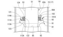
- the cushion member 82 has a first cushioning member 101 (first member) and a second cushioning member 102 (second member).
- the first cushioning member 101 is an elastic member and is formed in an annular shape, specifically an annular shape.
- the first cushioning member 101 has an outer peripheral surface portion 111, an inner peripheral surface portion 112, an end surface portion 113, and an end surface portion 114, as shown in FIG.
- the outer peripheral surface portion 111 is cylindrical.
- the inner peripheral surface portion 112 is cylindrical.
- the outer peripheral surface portion 111 and the inner peripheral surface portion 112 are arranged coaxially.
- the end face portion 113 is planar.
- the end face portion 113 spreads radially inwardly of the outer peripheral face portion 111 from one axial end edge portion of the outer peripheral face portion 111 and is connected to one axial end edge portion of the inner peripheral face portion 112 .
- the end surface portion 113 spreads within a plane perpendicular to the central axis of the outer peripheral surface portion 111 and the inner peripheral surface portion 112 .
- the end face portion 114 is planar.
- the end surface portion 114 spreads radially inward of the outer peripheral surface portion 111 from the edge portion on the opposite side of the end surface portion 113 in the axial direction of the outer peripheral surface portion 111 and extends axially opposite to the end surface portion 113 of the inner peripheral surface portion 112 . connected to the side edge.
- the end surface portion 114 spreads within a plane perpendicular to the central axis of the outer peripheral surface portion 111 and the inner peripheral surface portion 112 .
- the second cushioning member 102 is an elastic member and is formed in an annular shape, specifically an annular shape.
- the second cushioning member 102 has an outer peripheral surface portion 121 , an inner peripheral surface portion 122 , an end surface portion 123 and an end surface portion 124 .
- the outer peripheral surface portion 121 is cylindrical.
- the inner peripheral surface portion 122 is cylindrical.
- the diameter of the outer peripheral surface portion 121 that is, the outer diameter of the second cushioning member 102 is slightly larger than the diameter of the inner peripheral surface portion 112 , that is, the inner diameter of the first cushioning member 101 .
- the diameter of the inner peripheral surface portion 122 is slightly smaller than the diameter of the outer peripheral surface portion 53 of the main shaft portion 51 of the piston rod 50 , that is, the outer diameter of the main shaft portion 51 .
- the outer peripheral surface portion 121 and the inner peripheral surface portion 122 are arranged coaxially.
- the end surface portion 123 is planar.
- the end face portion 123 spreads radially inwardly of the outer peripheral face portion 121 from one axial end edge portion of the outer peripheral face portion 121 and is connected to one axial end edge portion of the inner peripheral face portion 122 .
- the end surface portion 123 spreads within a plane perpendicular to the central axis of the outer peripheral surface portion 121 and the inner peripheral surface portion 122 .
- the end face portion 124 is planar.
- the end surface portion 124 spreads radially inward of the outer peripheral surface portion 121 from the edge portion on the opposite side of the end surface portion 123 in the axial direction of the outer peripheral surface portion 121 and extends opposite to the end surface portion 123 in the axial direction of the inner peripheral surface portion 122 . connected to the side edge.
- the end surface portion 124 spreads within a plane perpendicular to the central axis of the outer peripheral surface portion 121 and the inner peripheral surface portion 122 .
- the axial length of the second cushioning member 102 is longer than the axial length of the first cushioning member 101 .
- the first cushioning member 101 has a smaller axial length than the second cushioning member 102 .
- the distance between end surfaces 123 and 124 is greater than the distance between end surfaces 113 and 114 .
- the difference between the outer diameter and the inner diameter of the second cushioning member 102 is equivalent to the difference between the outer diameter and the inner diameter of the first cushioning member 101 .
- the radial thickness of the second cushioning member 102 is the same as the radial thickness of the first cushioning member 101 .
- the second cushioning member 102 is arranged radially inside the first cushioning member 101 . At that time, the outer peripheral surface portion 121 of the second cushioning member 102 is in contact with the inner peripheral surface portion 112 of the first cushioning member 101 over the entire circumference. The second cushioning member 102 is fitted radially inwardly of the first cushioning member 101 with an interference.
- the cushion member 82 is integrally constructed by coaxially arranging the first cushioning member 101 and the second cushioning member 102 .
- the end surface portion 123 of the second cushioning member 102 and the end surface portion 113 of the first cushioning member 101 are aligned in the axial direction of the first cushioning member 101 and the second cushioning member 102 .
- the end surface portion 124 of the second cushioning member 102 is opposite to the end surface portions 113, 123 rather than the end surface portion 114 of the first cushioning member 101. located on the side.
- the cushion member 82 is configured such that the first cushioning member 101 and the second cushioning member 102 are connected to the rod guide 28 in a state in which the piston rod 50 is inserted radially inwardly of the second cushioning member 102 . It is arranged between the stopper member 81 and the stopper member 81 . Thereby, the first damping member 101 and the second damping member 102 are provided between the piston 45 and the rod guide 28 in the axial direction of the piston rod 50 . In other words, the cushion member 82 having the first cushioning member 101 and the second cushioning member 102 is provided between the piston 45 and the rod guide 28 . At that time, the second buffer member 102 is fitted to the main shaft portion 51 of the piston rod 50 with an interference.
- the inner peripheral surface portion 122 shown in FIG. 2 is pressed against the outer peripheral surface portion 53 of the main shaft portion 51 .
- the first buffer member 101 and the second buffer member 102 come into contact with the contact surface 93 of the stopper member 81 at the end surface portions 113 and 123 thereof in the axial direction of the piston rod 50 .
- the first damping member 101 and the second damping member 102 have end surface portions 114 and 124 opposed to the end surface 29 of the rod guide 28 shown in FIG. 1 in the axial direction of the piston rod 50 .
- the second buffer member 102 may have a gap in the radial direction with respect to the outer peripheral surface portion 53 of the piston rod 50 .
- the cushion member 82 having the first cushioning member 101 and the second cushioning member 102 contacts the rod guide 28 due to the extension of the piston rod 50 from the rod guide 28 and the seal member 41 .
- the first buffer member 101 and the second buffer member 102 come into contact with the rod guide 28 before the first buffer member 101 comes into contact with the second buffer member 102 .
- the second buffer member 102 of the cushion member 82 that abuts against the stopper member 81 is shown in FIG.
- the end surface portion 124 contacts the end surface 29 of the rod guide 28 shown in FIG.
- the moving speed of the piston rod 50 with respect to the rod guide 28 is further suppressed.
- the cushion member 82 is axially compressed and deformed to its limit, the piston rod 50 stops relative to the rod guide 28 , ie, the cylinder 17 .
- the cylinder device 11 is arranged so that the cushion member 82 bends the two first cushioning member 101 and the second cushioning member 102 against the rod guide 28 so that the deflection/load acts in parallel on the outer peripheral side and the inner peripheral side. are placed in
- the cylinder device 11 by making the axial lengths of the first damping member 101 and the second damping member 102 different, the contact timing of the first damping member 101 and the second damping member 102 with the rod guide 28 can be made different. I'm letting
- the first cushioning member 101 and the second cushioning member 102 are cushion materials made of different materials with different hardness.
- the hardness of the second cushioning member 102 is smaller than that of the first cushioning member 101 .
- the second cushioning member 102 made of a soft material comes into contact with the rod guide 28 before the first cushioning member 101 made of a hard material.
- the cushion member 82 is arranged so that the second cushioning member 102 made of a soft material is radially inside and the first cushioning member 101 made of a hard material is radially inside the first cushioning member 101 and the second cushioning member 102. It is placed outside.
- the first cushioning member 101 has greater hardness than the second cushioning member 102 .
- the first cushioning member 101 receives a larger load per unit deformation length in the axial direction than the second cushioning member 102 .
- the first cushioning member 101 is made of resin.
- the first cushioning member 101 is made of PA66 (nylon 66).
- the first cushioning member 101 includes, for example, PC (polycarbonate), PA6 (nylon 6), POM (polyacetal), PBT (polybutylene terephthalate), PPA (polyphthalamide), PPS (polyphenylene sulfide), It consists of PEEK (polyetheretherketone), PTFE (polytetrafluoroethylene), PFA (perfluoroalkoxyalkane), etc., and those containing carbon-based reinforcing materials and fillers with reinforcing effects such as glass fibers.
- PC polycarbonate
- PA6 nonylon 6
- POM polyacetal
- PBT polybutylene terephthalate
- PPA polyphthalamide
- PPS polyphenylene sulfide
- PEEK polyetheretherketone
- PTFE polytetrafluoroethylene
- PFA perfluoroalkoxyalkane
- the first cushioning member 101 may also be, for example, PE (polyethylene)-based TPEE (thermoplastic elastomer), PA (nylon)-based TPEE, PP (polypropylene)-based TPEE, U (urethane)-based TPEE, CFRP (carbon fiber reinforced plastic). , FKM (vinylidene fluoride-based fluororubber), etc., or those containing a reinforcing filler such as a carbon-based reinforcing material or glass fiber.
- PE polyethylene
- PA nylon-based TPEE
- PP polypropylene-based TPEE
- U urethane
- CFRP carbon fiber reinforced plastic
- FKM vinylidene fluoride-based fluorororubber
- those containing a reinforcing filler such as a carbon-based reinforcing material or glass fiber.
- the second cushioning member 102 has a lower hardness than the first cushioning member 101 .
- the second cushioning member 102 receives a load per unit deformation length in the axial direction smaller than that of the first cushioning member 101 .
- the second cushioning member 102 is made of an elastomer with large flexibility.
- the second cushioning member 102 is made of NBR (nitrile rubber).
- the second cushioning member 102 includes, for example, NR (natural rubber), IR (synthetic natural rubber), SBR (styrene butadiene rubber), BR (butadiene rubber), CR (chloroprene rubber), and IIR (butyl rubber).
- EPDM ethylene propylene rubber
- CSM chlorosulfonated polyethylene rubber
- ACM acrylic rubber
- U urethane rubber
- H-NBR hydrogenated nitrile rubber
- VMQ silicone rubber
- FVMQ fluorosilicone rubber
- FKM fluororubber
- the second cushioning member 102 may also be, for example, PE-based TPEE, PA-based TPEE, PP-based TPEE, U-based TPEE, or those containing fillers having reinforcing effects such as carbon-based reinforcing materials and glass fibers.
- the first cushioning member 101 and the second cushioning member 102 may be integrally formed at the molding stage instead of being integrally formed by fitting.
- the cushion member 82 abuts against the rod guide 28 due to the extension of the piston rod 50 from the rod guide 28 and the seal member 41 .
- the cushion member 82 is elastically deformed in the axial direction when the second cushioning member 102 comes into contact with the rod guide 28 earlier than the first cushioning member 101 , and then the cushion member 82 contacts the rod guide 28 with the first cushioning member 102 .
- 101 and the second cushioning member 102 are brought into contact with each other and elastically deformed in the axial direction.
- the cushion member 82 is designed so that both the first cushioning member 101 and the second member contact the rod guide 28 after that, rather than the first load characteristic that occurs after the second cushioning member 102 comes into contact with the rod guide 28 .
- the load received per unit deformation length is greater in the second load characteristic generated after contact.
- the cushion member 82 has a first load characteristic generated after the second cushioning member 102 abuts against the rod guide 28 and a load characteristic when the second cushioning member 102 and the first cushioning member 101 abut against the rod guide 28 . a second load characteristic that occurs later and has a greater load than the first load characteristic.
- the opening 24 side of the outer cylinder 16 is covered with a bumper cap 131 .
- the bumper cap 131 is an integrally molded product of synthetic resin and has a mounting portion 132 and a cover portion 133 .
- the mounting portion 132 is cylindrical.
- the cover portion 133 is in the shape of a perforated disc, and spreads radially inward from the end edge portion of the mounting portion 132 on the one end side in the axial direction.
- the mounting portion 132 of the bumper cap 131 is fitted to the body member 20 of the outer cylinder 16 so as to cover the outer peripheral surface thereof. Thereby, the bumper cap 131 is fixed to the outer cylinder 16 .
- the cover portion 133 of the bumper cap 131 covers the opening portion 24 side of the outer cylinder 16 and the seal member 41 .
- the piston rod 50 passes through the radially inner side of the cover portion 133 .
- the piston rod 50 is connected to the vehicle body side, and the mounting eye 25 fixed to the outer cylinder 16 is connected to the wheel side.
- a bump rubber 141 made of an elastic resin material is arranged between the bumper cap 131 attached to the cylinder device 11 and the vehicle body.
- the bump rubber 141 has a bellows tubular shape and is supported by the vehicle body with the main shaft portion 51 of the piston rod 50 inserted therein.
- the bumper cap 131 prevents the bump rubber 141 from interfering with the seal member 41 by abutting the cover portion 133 on the bump rubber 141 .
- Patent Documents 1 to 3 describe a cylinder device provided with a cushion that mitigates the impact when the piston rod is fully extended.
- Patent Document 1 discloses that nylon having high hardness and NBR having low hardness are connected in series.
- Japanese Patent Laid-Open No. 2002-200001 discloses a cylinder in which a cushion is arranged in a storage portion in order to prevent the cushion from being caught in the inner periphery of the cylinder.
- Patent Document 3 discloses a cushion in which a deformation restricting member is accommodated.
- the cushion is composed only of highly rigid members, even if the shape and size are devised, it is necessary to arrange multiple members in series in the axial direction of the piston rod in order to satisfy the high deflection characteristics. , especially in the axial direction.
- a coil spring made of metal and an elastic body such as rubber are arranged in series, not only does the size increase, but it also causes abnormal noise. Therefore, in any case, the size of the cushion is increased, and it is difficult to achieve a compact configuration. As a result, it is difficult to apply to a cylinder device with a small cylinder diameter or a cylinder device that requires a shortened shaft length.
- the cushion member 82 is located radially inward of the first cushioning member 101 and the first cushioning member 101 and contacts the rod guide 28 before the first cushioning member 101. It has a second cushioning member 102 having a lower hardness than the first cushioning member 101 and in contact therewith. In the cushion member 82 , the first cushioning member 101 and the second cushioning member 102 apply force to the rod guide 28 in parallel. As a result, the second cushioning member 102, which has a lower hardness than the first cushioning member 101, comes into contact with the rod guide 28 first and is deformed, thereby obtaining a high deflection characteristic that allows large deflection even with a small load.
- the second cushioning member 102 and the first cushioning member 101 having greater hardness act on the rod guide 28 in parallel.
- a high load characteristic is obtained in which the load received per unit deformation length in the axial direction is increased. Therefore, the cushion member 82 can effectively absorb the impact.
- the cushion member can be made more compact and more durable than the case where the cushion member is composed only of members with low hardness.
- it is not necessary to arrange a plurality of members in series so the size can be made compact.
- the second cushioning member 102 is located radially inward of the first cushioning member 101, the structure is more compact and the cost is reduced. Therefore, it is possible to effectively mitigate the impact when the piston rod 50 is fully extended with a compact structure.
- the cylinder device 11 has a first load characteristic generated after the second buffer member 102 of the cushion member 82 abuts against the rod guide 28 and a a second load characteristic of a greater load than the first load characteristic that occurs after contact.
- the first load characteristic is a high deflection characteristic that allows large deflection even with a small load
- the second load characteristic is a high load characteristic that increases the load received per unit deformation length in the axial direction. Therefore, the cushion member 82 can effectively absorb the impact.
- the cushion member can be made more compact and its durability can be improved as compared with the case where the cushion member is composed only of members with low hardness.
- the cushion member can be made compact as compared with the case where the cushion member is composed only of members having high hardness. Therefore, it is possible to effectively absorb the shock when the piston rod is fully extended with a cushion member having a compact structure.
- both the first cushioning member 101 and the second cushioning member 102 are formed in an annular shape, and the second cushioning member 102 is arranged on the inner peripheral side of the first cushioning member 101 . Therefore, even if the second cushioning member 102 that comes into contact with the rod guide 28 first among the first cushioning member 101 and the second cushioning member 102 is greatly crushed, the radially outward deformation is prevented by the first cushioning member 101 . inhibits. Further, even if the second cushioning member 102 swells, the first cushioning member 101 suppresses its radially outward deformation. Therefore, it is possible to prevent the second buffer member 102 from coming into contact with the inner cylinder 15 when the diameter of the cylinder device 11 is reduced.
- the cushion member 82 comes into contact with the inner cylinder 15, inhibiting the movement of the oil on both sides of the cushion member 82, and inhibiting the movement of the piston rod 50 toward the bottom portion 23, resulting in a so-called hydraulic lock state. can be suppressed.
- the axial length of the first buffer member 101 is smaller than that of the second buffer member 102 . Therefore, the second cushioning member 102 can be easily brought into contact with the rod guide 28 earlier than the first cushioning member 101 .
- the cylinder device 11 is configured such that the first damping member 101 and the second damping member 102 are integrally formed. Therefore, attachment to the piston rod 50 and component management are facilitated.
- integrally forming the first cushioning member 101 and the second cushioning member 102 at the time of molding it is possible to omit a process for integrating them.
- the rebound stopper 80 of the cylinder device 11 does not have a metallic coil spring, it is possible to suppress the generation of abnormal noise.
- a rebound stopper 80 ⁇ /b>A that is partially different from the rebound stopper 80 is provided instead of the rebound stopper 80 .
- the rebound stopper 80A has a cushion member 82A partially different from the cushion member 82 instead of the cushion member 82.
- the cushion member 82 ⁇ /b>A has a first cushioning member 101 ⁇ /b>A (first member) that is partially different from the first cushioning member 101 instead of the first cushioning member 101 .
- the first cushioning member 101A has an outer peripheral surface portion 111A, an inner peripheral surface portion 112A, an end surface portion 113A, and an end surface portion 114A.
- the outer peripheral surface portion 111A differs from the outer peripheral surface portion 111 in that it has a larger diameter than the outer peripheral surface portion 111 .
- the inner peripheral surface portion 112 ⁇ /b>A differs from the inner peripheral surface portion 112 in that it has a larger diameter than the inner peripheral surface portion 112 .
- the end face portion 113A differs from the end face portion 113 in that its inner diameter is larger than that of the end face portion 113 and its outer diameter is larger than that of the end face portion 113 .
- the end face portion 114A differs from the end face portion 114 in that its inner diameter is larger than that of the end face portion 114 and its outer diameter is larger than that of the end face portion 114 .
- the diameter of the inner peripheral surface portion 112A of the first cushioning member 101A is larger than the diameter of the outer peripheral surface portion 121, that is, the outer diameter of the second cushioning member . Therefore, when the second cushioning member 102 is arranged radially inward of the first cushioning member 101A, it provides a radial gap with respect to the first cushioning member 101A. Therefore, except when the second cushioning member 102 is deformed, the contact portion of the outer peripheral surface portion 121 with the inner peripheral surface portion 112A of the first cushioning member 101A does not cover the entire circumference of the outer peripheral surface portion 121 .
- Such a rebound stopper 80A is also attached to the piston rod 50 in the same manner as the rebound stopper 80 and operates in the same manner as the rebound stopper 80.
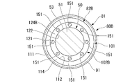
- a rebound stopper 80B that is partially different from the rebound stopper 80 is provided instead of the rebound stopper 80.
- the rebound stopper 80B has a cushion member 82B that is partially different from the cushion member 82 instead of the cushion member 82.
- the cushion member 82B has a second cushioning member 102B (second member) that is partially different from the second cushioning member 102 instead of the second cushioning member 102.
- second member second member
- the second cushioning member 102B has a through hole 151 axially penetrating through the second cushioning member 102B at a position between the outer peripheral surface portion 121 and the inner peripheral surface portion 122 in the radial direction.
- a plurality of (specifically, eight) through holes 151 are formed in the second cushioning member 102B at equal intervals in the circumferential direction.
- the second cushioning member 102B has an end surface portion 124B that is different from the end surface portion 124 in that the through hole 151 is opened.
- the second cushioning member 102B has an end face portion that is different from the end face portion 123 in that the through hole 151 is opened.
- Such a rebound stopper 80B is also attached to the piston rod 50 in the same manner as the rebound stopper 80 and operates in the same manner as the rebound stopper 80. Since a plurality of through holes 151 are formed in the rebound stopper 80B, the hardness thereof is lower than that of the rebound stopper 80, and compressive deformation in the axial direction is facilitated.
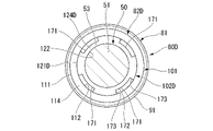
- a rebound stopper 80 ⁇ /b>C that is partially different from the rebound stopper 80 is provided instead of the rebound stopper 80 .
- the rebound stopper 80 ⁇ /b>C has a cushion member 82 ⁇ /b>C that is partially different from the cushion member 82 instead of the cushion member 82 .
- the cushion member 82C has a second cushioning member 102C (second member) that is partially different from the second cushioning member 102 instead of the second cushioning member 102. As shown in FIG.
- a groove portion 161 is formed in the radially inner portion of the second cushioning member 102C.
- the groove portion 161 extends in the axial direction of the second cushioning member 102C and penetrates the second cushioning member 102C in the axial direction.
- a plurality of (specifically, four) grooves 161 are formed at equal intervals in the circumferential direction of the second buffer member 102C.
- the second cushioning member 102C has an inner peripheral surface portion 122C that differs from the inner peripheral surface portion 122 in that it is formed of a plurality of grooves 161 .
- the second buffer member 102C has an end face portion 124C that differs from the end face portion 124 in that the groove portion 161 opens.
- the second cushioning member 102C has an end face portion that differs from the end face portion 123 in that the groove portion 161 opens.
- the groove portion 161 has a planar surface portion 162 and a pair of planar surface portions 163 .
- the surface portion 162 extends along the tangential direction of the outer peripheral surface portion 121 and along the axial direction of the outer peripheral surface portion 121 .
- the pair of surface portions 163 spread along the axial direction of the outer peripheral surface portion 121 .
- the pair of surface portions 163 spreads from both end edge portions of the surface portion 162 in the circumferential direction of the outer peripheral surface portion 121 toward the center axis of the outer peripheral surface portion 121 .
- the pair of surface portions 163 widen apart from each other in the circumferential direction of the outer peripheral surface portion 121 as they approach the central axis of the outer peripheral surface portion 121 .
- the surface portion 162 and the pair of planar surface portions 163 form an isosceles trapezoidal shape as a whole.
- Such a rebound stopper 80 ⁇ /b>C is also attached to the piston rod 50 in the same manner as the rebound stopper 80 and operates in the same manner as the rebound stopper 80 . Since the rebound stopper 80 ⁇ /b>C has a plurality of grooves 161 formed therein, the hardness of the rebound stopper 80 ⁇ /b>C is lower than that of the rebound stopper 80 , and compressive deformation in the axial direction is facilitated.
- a rebound stopper 80 ⁇ /b>D that is partially different from the rebound stopper 80 is provided instead of the rebound stopper 80 .
- the rebound stopper 80 ⁇ /b>D has a cushion member 82 ⁇ /b>D that is partially different from the cushion member 82 instead of the cushion member 82 .
- the cushion member 82 ⁇ /b>D has a second cushioning member 102 ⁇ /b>D (second member) that is partially different from the second cushioning member 102 instead of the second cushioning member 102 .
- a groove portion 171 is formed in the radially outer portion of the second cushioning member 102D.
- the groove portion 171 extends in the axial direction of the second cushioning member 102D and penetrates the second cushioning member 102D in the axial direction.
- a plurality of (specifically, four) grooves 171 are formed at equal intervals in the circumferential direction of the second cushioning member 102D.
- the second cushioning member 102D has an outer peripheral surface portion 121D that differs from the outer peripheral surface portion 121 in that the groove portion 171 opens.
- the second buffer member 102D has an end surface portion 124D that differs from the end surface portion 124 in that the groove portion 171 opens.
- the second cushioning member 102D has an end face portion that differs from the end face portion 123 in that the groove portion 171 opens.
- the groove portion 171 has a surface portion 172 shaped like a part of a cylindrical surface and a pair of planar surface portions 173 .
- the surface portion 172 is arranged on a cylindrical surface coaxial with the inner peripheral surface portion 122 .
- the pair of surface portions 173 spread outward in the radial direction of the inner peripheral surface portion 122 from both end edge portions of the surface portion 172 in the circumferential direction of the inner peripheral surface portion 122 .
- the pair of surface portions 173 spread along the radial direction of the inner peripheral surface portion 122 and along the axial direction of the inner peripheral surface portion 122 .
- Such a rebound stopper 80 ⁇ /b>D is also attached to the piston rod 50 in the same manner as the rebound stopper 80 and operates in the same manner as the rebound stopper 80 . Since the rebound stopper 80 ⁇ /b>D has a plurality of grooves 171 formed therein, the hardness thereof is lower than that of the rebound stopper 80 , and compressive deformation in the axial direction is facilitated.
- the axial length of the first cushioning member 101 is set to the second length as a configuration for bringing the second cushioning member 102 into contact with the rod guide 28 earlier than the first cushioning member 101.
- the axial length of the first cushioning member 101 and the axial length of the second cushioning member 102 may be made equal, and the rod guide 28 may be provided with unevenness.
- the outer peripheral side of the end face 29 of the rod guide 28 is recessed in the axial direction. This also allows the second cushioning member 102 to come into contact with the rod guide 28 earlier than the first cushioning member 101 .
- the double-tube cylinder device 11 was described as an example, but the above structure can also be applied to a single-tube cylinder device.
- a free piston is provided on the opposite side of the second chamber 49 from the first chamber 48, and a gas chamber is provided on the opposite side of the free piston from the second chamber 49. .
- Cylinder device 17 Cylinder 24 Opening 28 Rod guide (blocking member) 41 Sealing member (blocking member) 45 Piston 50 Piston rod 81 Stopper member 82, 82A ⁇ 82D... Cushion member, 101, 101A... First cushioning member (first member), 102, 102B to 102D... Second cushioning member (second member).
Landscapes
- Engineering & Computer Science (AREA)
- General Engineering & Computer Science (AREA)
- Mechanical Engineering (AREA)
- Fluid-Damping Devices (AREA)
Priority Applications (5)
| Application Number | Priority Date | Filing Date | Title |
|---|---|---|---|
| DE112022004605.8T DE112022004605T5 (de) | 2021-09-28 | 2022-09-16 | Zylindervorrichtung |
| KR1020247002862A KR20240023658A (ko) | 2021-09-28 | 2022-09-16 | 실린더 장치 |
| JP2023551320A JPWO2023054007A1 (https=) | 2021-09-28 | 2022-09-16 | |
| CN202280048364.XA CN117642565A (zh) | 2021-09-28 | 2022-09-16 | 缸装置 |
| US18/689,888 US20240426364A1 (en) | 2021-09-28 | 2022-09-16 | Cylinder device |
Applications Claiming Priority (2)
| Application Number | Priority Date | Filing Date | Title |
|---|---|---|---|
| JP2021157446 | 2021-09-28 | ||
| JP2021-157446 | 2021-09-28 |
Publications (1)
| Publication Number | Publication Date |
|---|---|
| WO2023054007A1 true WO2023054007A1 (ja) | 2023-04-06 |
Family
ID=85782504
Family Applications (1)
| Application Number | Title | Priority Date | Filing Date |
|---|---|---|---|
| PCT/JP2022/034686 Ceased WO2023054007A1 (ja) | 2021-09-28 | 2022-09-16 | シリンダ装置 |
Country Status (6)
| Country | Link |
|---|---|
| US (1) | US20240426364A1 (https=) |
| JP (1) | JPWO2023054007A1 (https=) |
| KR (1) | KR20240023658A (https=) |
| CN (1) | CN117642565A (https=) |
| DE (1) | DE112022004605T5 (https=) |
| WO (1) | WO2023054007A1 (https=) |
Citations (8)
| Publication number | Priority date | Publication date | Assignee | Title |
|---|---|---|---|---|
| JPS6137880Y2 (https=) * | 1980-01-19 | 1986-11-01 | ||
| JPS62202543U (https=) * | 1986-06-13 | 1987-12-24 | ||
| JPH08233020A (ja) * | 1995-02-28 | 1996-09-10 | Kayaba Ind Co Ltd | 伸び切りクッション構造 |
| JPH0914328A (ja) * | 1995-06-27 | 1997-01-14 | Kayaba Ind Co Ltd | 油圧緩衝器におけるリバウンドクッション装置 |
| JP2001065511A (ja) * | 1999-08-26 | 2001-03-16 | Sakagami Seisakusho Ltd | シリンダの緩衝リング |
| KR20040039649A (ko) * | 2002-11-04 | 2004-05-12 | 주식회사 만도 | 쇽 업소버의 스톱러버 |
| US20080314707A1 (en) * | 2007-06-20 | 2008-12-25 | Saiman Lun | Damper having a rebound bumper and damper subassembly having same |
| JP2015108414A (ja) * | 2013-12-05 | 2015-06-11 | Nok株式会社 | 緩衝体 |
Family Cites Families (2)
| Publication number | Priority date | Publication date | Assignee | Title |
|---|---|---|---|---|
| JP2006046509A (ja) | 2004-08-05 | 2006-02-16 | Kayaba Ind Co Ltd | 油圧緩衝器 |
| JP6868175B1 (ja) | 2020-03-26 | 2021-05-12 | 株式会社鈴康 | プログラム、情報処理方法及び情報処理システム |
-
2022
- 2022-09-16 CN CN202280048364.XA patent/CN117642565A/zh active Pending
- 2022-09-16 DE DE112022004605.8T patent/DE112022004605T5/de active Pending
- 2022-09-16 WO PCT/JP2022/034686 patent/WO2023054007A1/ja not_active Ceased
- 2022-09-16 JP JP2023551320A patent/JPWO2023054007A1/ja active Pending
- 2022-09-16 US US18/689,888 patent/US20240426364A1/en active Pending
- 2022-09-16 KR KR1020247002862A patent/KR20240023658A/ko not_active Abandoned
Patent Citations (8)
| Publication number | Priority date | Publication date | Assignee | Title |
|---|---|---|---|---|
| JPS6137880Y2 (https=) * | 1980-01-19 | 1986-11-01 | ||
| JPS62202543U (https=) * | 1986-06-13 | 1987-12-24 | ||
| JPH08233020A (ja) * | 1995-02-28 | 1996-09-10 | Kayaba Ind Co Ltd | 伸び切りクッション構造 |
| JPH0914328A (ja) * | 1995-06-27 | 1997-01-14 | Kayaba Ind Co Ltd | 油圧緩衝器におけるリバウンドクッション装置 |
| JP2001065511A (ja) * | 1999-08-26 | 2001-03-16 | Sakagami Seisakusho Ltd | シリンダの緩衝リング |
| KR20040039649A (ko) * | 2002-11-04 | 2004-05-12 | 주식회사 만도 | 쇽 업소버의 스톱러버 |
| US20080314707A1 (en) * | 2007-06-20 | 2008-12-25 | Saiman Lun | Damper having a rebound bumper and damper subassembly having same |
| JP2015108414A (ja) * | 2013-12-05 | 2015-06-11 | Nok株式会社 | 緩衝体 |
Also Published As
| Publication number | Publication date |
|---|---|
| KR20240023658A (ko) | 2024-02-22 |
| DE112022004605T5 (de) | 2024-07-18 |
| US20240426364A1 (en) | 2024-12-26 |
| CN117642565A (zh) | 2024-03-01 |
| JPWO2023054007A1 (https=) | 2023-04-06 |
Similar Documents
| Publication | Publication Date | Title |
|---|---|---|
| US9360078B2 (en) | Hydraulic shock absorber | |
| US10400843B2 (en) | Damper | |
| JP7118169B2 (ja) | 緩衝器 | |
| US20020063024A1 (en) | Hydraulic shock absorber | |
| CN106233026A (zh) | 缓冲器 | |
| CN112771284A (zh) | 缓冲器 | |
| WO2023054007A1 (ja) | シリンダ装置 | |
| JP7450583B2 (ja) | 緩衝器 | |
| JP6072270B2 (ja) | シリンダ装置およびシール部材 | |
| JP6443985B2 (ja) | シリンダ装置 | |
| KR20200002977A (ko) | 완충기 | |
| JP7515441B2 (ja) | 緩衝器 | |
| JP2021139439A (ja) | シリンダ装置 | |
| JP2023064207A (ja) | シリンダ装置 | |
| JP7770252B2 (ja) | シリンダ装置 | |
| US7559272B2 (en) | Cylinder apparatus | |
| JP2016188650A (ja) | シリンダ装置 | |
| JP2025178915A (ja) | 緩衝器 | |
| JP2013204748A (ja) | 流体圧緩衝器 | |
| JP7285750B2 (ja) | 緩衝器 | |
| JP2024048444A (ja) | 油圧緩衝器 | |
| JP7154199B2 (ja) | 緩衝器 | |
| JP2018135946A (ja) | シリンダ装置 | |
| JP7103723B2 (ja) | 緩衝器 | |
| CN121511365A (zh) | 缓冲器 |
Legal Events
| Date | Code | Title | Description |
|---|---|---|---|
| 121 | Ep: the epo has been informed by wipo that ep was designated in this application |
Ref document number: 22875878 Country of ref document: EP Kind code of ref document: A1 |
|
| WWE | Wipo information: entry into national phase |
Ref document number: 202280048364.X Country of ref document: CN |
|
| ENP | Entry into the national phase |
Ref document number: 20247002862 Country of ref document: KR Kind code of ref document: A |
|
| WWE | Wipo information: entry into national phase |
Ref document number: 1020247002862 Country of ref document: KR |
|
| WWE | Wipo information: entry into national phase |
Ref document number: 2023551320 Country of ref document: JP |
|
| WWE | Wipo information: entry into national phase |
Ref document number: 18689888 Country of ref document: US |
|
| WWE | Wipo information: entry into national phase |
Ref document number: 112022004605 Country of ref document: DE |
|
| 122 | Ep: pct application non-entry in european phase |
Ref document number: 22875878 Country of ref document: EP Kind code of ref document: A1 |