WO2023054007A1 - Cylinder device - Google Patents
Cylinder device Download PDFInfo
- Publication number
- WO2023054007A1 WO2023054007A1 PCT/JP2022/034686 JP2022034686W WO2023054007A1 WO 2023054007 A1 WO2023054007 A1 WO 2023054007A1 JP 2022034686 W JP2022034686 W JP 2022034686W WO 2023054007 A1 WO2023054007 A1 WO 2023054007A1
- Authority
- WO
- WIPO (PCT)
- Prior art keywords
- cylinder
- cushioning member
- surface portion
- piston
- piston rod
- Prior art date
Links
- 230000002093 peripheral effect Effects 0.000 claims description 100
- 230000004323 axial length Effects 0.000 claims description 10
- 239000012530 fluid Substances 0.000 claims description 10
- 238000013016 damping Methods 0.000 description 14
- 239000007788 liquid Substances 0.000 description 10
- 229920001971 elastomer Polymers 0.000 description 8
- 229920006346 thermoplastic polyester elastomer Polymers 0.000 description 8
- 239000000463 material Substances 0.000 description 7
- 239000005060 rubber Substances 0.000 description 7
- 239000002184 metal Substances 0.000 description 6
- 229920000459 Nitrile rubber Polymers 0.000 description 5
- OKTJSMMVPCPJKN-UHFFFAOYSA-N Carbon Chemical compound [C] OKTJSMMVPCPJKN-UHFFFAOYSA-N 0.000 description 4
- 229910052799 carbon Inorganic materials 0.000 description 4
- 239000003365 glass fiber Substances 0.000 description 4
- -1 polybutylene terephthalate Polymers 0.000 description 4
- 239000012779 reinforcing material Substances 0.000 description 4
- 230000035939 shock Effects 0.000 description 4
- 244000043261 Hevea brasiliensis Species 0.000 description 3
- 229920002302 Nylon 6,6 Polymers 0.000 description 3
- 239000004698 Polyethylene Substances 0.000 description 3
- 239000004743 Polypropylene Substances 0.000 description 3
- 239000006096 absorbing agent Substances 0.000 description 3
- 229920003052 natural elastomer Polymers 0.000 description 3
- 229920001194 natural rubber Polymers 0.000 description 3
- 230000002829 reductive effect Effects 0.000 description 3
- 239000012763 reinforcing filler Substances 0.000 description 3
- 239000004677 Nylon Substances 0.000 description 2
- 229920002292 Nylon 6 Polymers 0.000 description 2
- 239000004813 Perfluoroalkoxy alkane Substances 0.000 description 2
- 239000004696 Poly ether ether ketone Substances 0.000 description 2
- 239000005062 Polybutadiene Substances 0.000 description 2
- 239000004734 Polyphenylene sulfide Substances 0.000 description 2
- 239000004954 Polyphthalamide Substances 0.000 description 2
- 230000002159 abnormal effect Effects 0.000 description 2
- 230000000903 blocking effect Effects 0.000 description 2
- 229920005549 butyl rubber Polymers 0.000 description 2
- 239000004918 carbon fiber reinforced polymer Substances 0.000 description 2
- 230000008602 contraction Effects 0.000 description 2
- 238000002788 crimping Methods 0.000 description 2
- 229920001973 fluoroelastomer Polymers 0.000 description 2
- 229920005560 fluorosilicone rubber Polymers 0.000 description 2
- 230000002401 inhibitory effect Effects 0.000 description 2
- 238000000465 moulding Methods 0.000 description 2
- 229920001778 nylon Polymers 0.000 description 2
- 229920011301 perfluoro alkoxyl alkane Polymers 0.000 description 2
- 229920001084 poly(chloroprene) Polymers 0.000 description 2
- 229920002857 polybutadiene Polymers 0.000 description 2
- 229920001707 polybutylene terephthalate Polymers 0.000 description 2
- 239000004417 polycarbonate Substances 0.000 description 2
- 229920002530 polyetherether ketone Polymers 0.000 description 2
- 229920006324 polyoxymethylene Polymers 0.000 description 2
- 229920000069 polyphenylene sulfide Polymers 0.000 description 2
- 229920006375 polyphtalamide Polymers 0.000 description 2
- 229920001343 polytetrafluoroethylene Polymers 0.000 description 2
- 239000004810 polytetrafluoroethylene Substances 0.000 description 2
- 230000003014 reinforcing effect Effects 0.000 description 2
- 229920005989 resin Polymers 0.000 description 2
- 239000011347 resin Substances 0.000 description 2
- 239000007779 soft material Substances 0.000 description 2
- 229920003048 styrene butadiene rubber Polymers 0.000 description 2
- 239000000725 suspension Substances 0.000 description 2
- BQCIDUSAKPWEOX-UHFFFAOYSA-N 1,1-Difluoroethene Chemical compound FC(F)=C BQCIDUSAKPWEOX-UHFFFAOYSA-N 0.000 description 1
- 229920002943 EPDM rubber Polymers 0.000 description 1
- JOYRKODLDBILNP-UHFFFAOYSA-N Ethyl urethane Chemical compound CCOC(N)=O JOYRKODLDBILNP-UHFFFAOYSA-N 0.000 description 1
- 229920000181 Ethylene propylene rubber Polymers 0.000 description 1
- 229930182556 Polyacetal Natural products 0.000 description 1
- 239000002174 Styrene-butadiene Substances 0.000 description 1
- 229920006311 Urethane elastomer Polymers 0.000 description 1
- 229920000800 acrylic rubber Polymers 0.000 description 1
- 239000011248 coating agent Substances 0.000 description 1
- 238000000576 coating method Methods 0.000 description 1
- 238000004891 communication Methods 0.000 description 1
- 230000006835 compression Effects 0.000 description 1
- 238000007906 compression Methods 0.000 description 1
- 238000010586 diagram Methods 0.000 description 1
- 239000000806 elastomer Substances 0.000 description 1
- 239000000945 filler Substances 0.000 description 1
- 229920002681 hypalon Polymers 0.000 description 1
- 230000002452 interceptive effect Effects 0.000 description 1
- 238000000034 method Methods 0.000 description 1
- 230000000116 mitigating effect Effects 0.000 description 1
- 239000000203 mixture Substances 0.000 description 1
- 230000036961 partial effect Effects 0.000 description 1
- 230000000149 penetrating effect Effects 0.000 description 1
- 229920000058 polyacrylate Polymers 0.000 description 1
- 229920000515 polycarbonate Polymers 0.000 description 1
- 229920000573 polyethylene Polymers 0.000 description 1
- 229920001155 polypropylene Polymers 0.000 description 1
- 238000007789 sealing Methods 0.000 description 1
- 229920002379 silicone rubber Polymers 0.000 description 1
- 239000004945 silicone rubber Substances 0.000 description 1
- 229920003002 synthetic resin Polymers 0.000 description 1
- 239000000057 synthetic resin Substances 0.000 description 1
- 229920002725 thermoplastic elastomer Polymers 0.000 description 1
- 238000003466 welding Methods 0.000 description 1
Images


Classifications
-
- F—MECHANICAL ENGINEERING; LIGHTING; HEATING; WEAPONS; BLASTING
- F16—ENGINEERING ELEMENTS AND UNITS; GENERAL MEASURES FOR PRODUCING AND MAINTAINING EFFECTIVE FUNCTIONING OF MACHINES OR INSTALLATIONS; THERMAL INSULATION IN GENERAL
- F16F—SPRINGS; SHOCK-ABSORBERS; MEANS FOR DAMPING VIBRATION
- F16F9/00—Springs, vibration-dampers, shock-absorbers, or similarly-constructed movement-dampers using a fluid or the equivalent as damping medium
- F16F9/003—Dampers characterised by having pressure absorbing means other than gas, e.g. sponge rubber
-
- F—MECHANICAL ENGINEERING; LIGHTING; HEATING; WEAPONS; BLASTING
- F16—ENGINEERING ELEMENTS AND UNITS; GENERAL MEASURES FOR PRODUCING AND MAINTAINING EFFECTIVE FUNCTIONING OF MACHINES OR INSTALLATIONS; THERMAL INSULATION IN GENERAL
- F16F—SPRINGS; SHOCK-ABSORBERS; MEANS FOR DAMPING VIBRATION
- F16F9/00—Springs, vibration-dampers, shock-absorbers, or similarly-constructed movement-dampers using a fluid or the equivalent as damping medium
- F16F9/32—Details
- F16F9/58—Stroke limiting stops, e.g. arranged on the piston rod outside the cylinder
Abstract
A cylinder device comprising: a piston rod (50), one end side of which is connected to a piston, and the other end side of which is inserted into a stopping member and extends to the outside of a cylinder; and a cushion member (82) that is provided between the piston and the stopping member, and is brought into contact with the stopping member by extension of the piston rod (50). The cushion member (82) has a first member (101) and a second member (102) that is radially inward of the first member (101), is brought into contact with the stopping member before the first member (101), and has a lower hardness than the first member (101). The first member (101) and the second member (102) exert a force in parallel on the stopping member.
Description
本発明は、シリンダ装置に関する。
本願は、2021年9月28日に、日本に出願された特願2021-157446号に基づき優先権を主張し、その内容をここに援用する。 The present invention relates to a cylinder device.
This application claims priority based on Japanese Patent Application No. 2021-157446 filed in Japan on September 28, 2021, the contents of which are incorporated herein.
本願は、2021年9月28日に、日本に出願された特願2021-157446号に基づき優先権を主張し、その内容をここに援用する。 The present invention relates to a cylinder device.
This application claims priority based on Japanese Patent Application No. 2021-157446 filed in Japan on September 28, 2021, the contents of which are incorporated herein.
シリンダ装置において、ピストンロッドの伸び切り時の衝撃を緩和するクッションを設けたものがある(例えば、特許文献1~3参照)。
In some cylinder devices, a cushion is provided to reduce the impact when the piston rod is fully extended (see Patent Documents 1 to 3, for example).
シリンダ装置において、コンパクトな構成でピストンロッドの伸び切り時の衝撃を効果的に緩和することが求められている。
In the cylinder device, there is a demand for a compact structure that effectively mitigates the impact when the piston rod is fully extended.
したがって、本発明は、コンパクトな構成でピストンロッドの伸び切り時の衝撃を効果的に緩和することが可能となるシリンダ装置の提供を目的とする。
Therefore, an object of the present invention is to provide a cylinder device that can effectively mitigate the impact when the piston rod is fully extended with a compact configuration.
上記目的を達成するために、本発明に係る第1の態様のシリンダ装置は、作動流体が封入されるシリンダと、前記シリンダ内に摺動可能に設けられるピストンと、前記シリンダの開口部側に設けられる閉塞部材と、一端側が前記ピストンに連結され他端側が前記閉塞部材に挿通されて前記シリンダの外部まで延出されるピストンロッドと、前記ピストンと前記閉塞部材との間に設けられ、前記ピストンロッドの伸長によって前記閉塞部材に当接するクッション部材と、を備える。前記クッション部材は、第1部材と、該第1部材の径方向内側にあって、前記閉塞部材に対し前記第1部材よりも先に当接する、前記第1部材よりも硬度が小さい第2部材と、を有し、前記閉塞部材に対し前記第1部材および前記第2部材は並列に力を作用させる。
In order to achieve the above object, a cylinder device according to a first aspect of the present invention comprises a cylinder in which a working fluid is enclosed, a piston slidably provided in the cylinder, and an opening side of the cylinder. a closing member provided; a piston rod having one end connected to the piston and the other end inserted through the closing member and extending to the outside of the cylinder; a cushion member that abuts against the closure member upon extension of the rod. The cushion member includes a first member and a second member located radially inside the first member and having a lower hardness than the first member and contacting the closing member before the first member. and, the first member and the second member apply forces in parallel to the closing member.
本発明に係る第2の態様のシリンダ装置は、作動流体が封入されるシリンダと、前記シリンダ内に摺動可能に設けられるピストンと、前記シリンダの開口部側に設けられる閉塞部材と、一端側が前記ピストンに連結され他端側が前記閉塞部材に挿通されて前記シリンダの外部まで延出されるピストンロッドと、前記ピストンと前記閉塞部材との間に設けられ、前記ピストンロッドの伸長によって前記閉塞部材に当接するクッション部材と、を備える。前記クッション部材は、第1部材と、該第1部材よりも硬度が小さい第2部材と、を有し、前記第2部材が前記閉塞部材に当接した後に発生する第1荷重特性と、前記第2部材と前記第1部材とが前記閉塞部材に当接した後に発生する、前記第1荷重特性よりも大きな荷重の第2荷重特性と、を有する。
A cylinder device according to a second aspect of the present invention includes a cylinder in which a working fluid is sealed, a piston slidably provided in the cylinder, a closing member provided on an opening side of the cylinder, and one end side of which is A piston rod connected to the piston and having the other end inserted through the closing member and extending to the outside of the cylinder; and a cushion member that abuts. The cushion member has a first member and a second member having a hardness lower than that of the first member, a first load characteristic generated after the second member comes into contact with the closing member; a second load characteristic of a load greater than the first load characteristic occurring after the second member and the first member abut the closure member.
本発明によれば、コンパクトな構成でピストンロッドの伸び切り時の衝撃を効果的に緩和することが可能となる。
According to the present invention, it is possible to effectively mitigate the impact when the piston rod is fully extended with a compact configuration.
[第1実施形態]
第1実施形態のシリンダ装置について、図1~図3を参照しつつ以下に説明する。
図1は、第1実施形態のシリンダ装置11およびその周辺部品を示す図である。シリンダ装置11は、自動車や鉄道車両等の車両のサスペンション装置に用いられる緩衝器(Shock absorber)である。シリンダ装置11は、具体的には自動車のサスペンション装置に用いられる油圧緩衝器である。シリンダ装置11は、内筒15と外筒16とを有するシリンダ17を備えた複筒式の油圧緩衝器である。内筒15は円筒状である。外筒16は内筒15よりも大径の有底筒状である。外筒16は内筒15の径方向外側に、内筒15と同軸状に設けられている。外筒16と内筒15との間はリザーバ室18となっている。 [First embodiment]
A cylinder device of the first embodiment will be described below with reference to FIGS. 1 to 3. FIG.
FIG. 1 is a diagram showing acylinder device 11 and peripheral parts thereof according to the first embodiment. The cylinder device 11 is a shock absorber used in suspension devices of vehicles such as automobiles and railroad vehicles. The cylinder device 11 is specifically a hydraulic shock absorber used in an automobile suspension device. The cylinder device 11 is a twin-tube hydraulic shock absorber having a cylinder 17 having an inner cylinder 15 and an outer cylinder 16 . The inner cylinder 15 is cylindrical. The outer cylinder 16 has a bottomed cylindrical shape with a larger diameter than the inner cylinder 15 . The outer cylinder 16 is provided radially outside the inner cylinder 15 and coaxially with the inner cylinder 15 . A reservoir chamber 18 is provided between the outer cylinder 16 and the inner cylinder 15 .
第1実施形態のシリンダ装置について、図1~図3を参照しつつ以下に説明する。
図1は、第1実施形態のシリンダ装置11およびその周辺部品を示す図である。シリンダ装置11は、自動車や鉄道車両等の車両のサスペンション装置に用いられる緩衝器(Shock absorber)である。シリンダ装置11は、具体的には自動車のサスペンション装置に用いられる油圧緩衝器である。シリンダ装置11は、内筒15と外筒16とを有するシリンダ17を備えた複筒式の油圧緩衝器である。内筒15は円筒状である。外筒16は内筒15よりも大径の有底筒状である。外筒16は内筒15の径方向外側に、内筒15と同軸状に設けられている。外筒16と内筒15との間はリザーバ室18となっている。 [First embodiment]
A cylinder device of the first embodiment will be described below with reference to FIGS. 1 to 3. FIG.
FIG. 1 is a diagram showing a
外筒16は胴部材20と底部材21とを有している。胴部材20は円筒状である。底部材21は、外周部が円筒状をなしており、この外周部において、胴部材20の軸方向の一方の端部に嵌合されて溶接により固定されている。底部材21の胴部材20との嵌合部分と、胴部材20とが、外筒16の円筒状の胴部22を構成する。底部材21の胴部材20との嵌合部分よりも径方向内側の部分が外筒16の底部23を構成する。底部23は、胴部22の軸方向の一方の端部を閉塞する。胴部22の軸方向における底部23とは反対側は開口部24となっている。外筒16の開口部24は、シリンダ17においても軸方向の一端に設けられる開口部となる。外筒16の底部23は、シリンダ17においても軸方向の他端に設けられる底部となる。言い換えれば、シリンダ17は、軸方向の一端が開口し、軸方向の他端が閉塞されている。底部23は、その径方向内側の部分が、軸方向において胴部材20とは反対方向に延出している。底部23の延出部分の先端に取付アイ25が固定されている。取付アイ25は車両の車輪側に連結される部分である。内筒15は、金属製の一部材からなる一体成形品であり、円筒状である。内筒15は、その内周面が円筒面状である。
The outer cylinder 16 has a body member 20 and a bottom member 21 . The body member 20 is cylindrical. The bottom member 21 has a cylindrical outer peripheral portion, and is fitted to one axial end of the body member 20 at the outer peripheral portion and fixed by welding. A fitting portion of the bottom member 21 with the trunk member 20 and the trunk member 20 form a cylindrical trunk portion 22 of the outer cylinder 16 . A portion of the bottom member 21 radially inward of the fitting portion of the body member 20 constitutes a bottom portion 23 of the outer cylinder 16 . The bottom portion 23 closes one axial end of the body portion 22 . An opening 24 is formed on the side opposite to the bottom 23 in the axial direction of the body 22 . The opening 24 of the outer cylinder 16 is also an opening provided at one axial end of the cylinder 17 . The bottom portion 23 of the outer cylinder 16 also serves as a bottom portion provided at the other end in the axial direction of the cylinder 17 as well. In other words, the cylinder 17 is open at one axial end and closed at the other axial end. A radially inner portion of the bottom portion 23 extends in the opposite direction to the body member 20 in the axial direction. A mounting eye 25 is fixed to the tip of the extending portion of the bottom portion 23 . The mounting eye 25 is a portion connected to the wheel side of the vehicle. The inner cylinder 15 is an integrally molded product made of one member made of metal and has a cylindrical shape. The inner cylinder 15 has a cylindrical inner peripheral surface.
シリンダ装置11は、バルブボディ27とロッドガイド28(閉塞部材)とを備えている。バルブボディ27は、円環状であり、内筒15および外筒16の軸方向の一端部に設けられている。ロッドガイド28は、円環状であり、内筒15および外筒16の軸方向の他端部に設けられている。バルブボディ27は、ベースバルブ30を構成するものであり、外周部が、大径部分とこれよりも小径の小径部分とを有する段差状をなしている。バルブボディ27は底部23に載置されている。その際に、バルブボディ27は、外周部の大径部分において外筒16に対し径方向に位置決めされる。
The cylinder device 11 includes a valve body 27 and a rod guide 28 (closure member). The valve body 27 has an annular shape and is provided at one axial end of the inner cylinder 15 and the outer cylinder 16 . The rod guide 28 has an annular shape and is provided at the other axial ends of the inner cylinder 15 and the outer cylinder 16 . The valve body 27 constitutes the base valve 30 and has a stepped outer peripheral portion having a large diameter portion and a smaller diameter portion. A valve body 27 rests on the bottom 23 . At that time, the valve body 27 is radially positioned with respect to the outer cylinder 16 at the large-diameter portion of the outer peripheral portion.
ロッドガイド28は、ロッドガイド本体32とカラー33とを有している。ロッドガイド本体32は、金属製であって円環状である。ロッドガイド本体32は、外周部が大径部分とこれよりも小径の小径部分とを有する段差状をなしている。カラー33は円筒状である。カラー33は、金属製の円筒体の内周面を摺動性の高い材料で被覆してなるものである。カラー33は、ロッドガイド本体32の内周部に嵌合されて固定されている。ロッドガイド28は、ロッドガイド本体32の外周部の大径部分が、外筒16の胴部22の開口部24側の内周部に嵌合する。ロッドガイド28は、その軸方向の底部23側の端部にある端面29が平面状である。端面29は、ロッドガイド28の中心軸線に対し直交する平面内で広がっている。端面29はロッドガイド本体32およびカラー33に形成されている。
The rod guide 28 has a rod guide body 32 and a collar 33. The rod guide body 32 is made of metal and has an annular shape. The rod guide main body 32 has a stepped outer peripheral portion having a large-diameter portion and a small-diameter portion having a smaller diameter than the large-diameter portion. Collar 33 is cylindrical. The collar 33 is formed by coating the inner peripheral surface of a metal cylindrical body with a highly slidable material. The collar 33 is fitted and fixed to the inner peripheral portion of the rod guide body 32 . The large-diameter portion of the outer peripheral portion of the rod guide main body 32 of the rod guide 28 is fitted to the inner peripheral portion of the body portion 22 of the outer cylinder 16 on the side of the opening 24 . The rod guide 28 has a planar end face 29 at the end on the bottom 23 side in the axial direction. The end face 29 extends in a plane perpendicular to the central axis of the rod guide 28 . End face 29 is formed on rod guide body 32 and collar 33 .
内筒15は、軸方向の一端部が、バルブボディ27の外周部の小径部分に嵌合されている。内筒15は、軸方向の一端部が、バルブボディ27を介して外筒16の底部23に載置されている。また、内筒15は、軸方向の他端部が、ロッドガイド本体32の外周部の小径部分に嵌合されている。内筒15は、この他端部が、ロッドガイド28を介して外筒16の胴部22に嵌合している。この状態で、内筒15は、外筒16に対して軸方向および径方向に位置決めされる。ここで、バルブボディ27と底部23との間は、バルブボディ27に形成された通路溝40を介して内筒15と外筒16との間に連通している。バルブボディ27と底部23との間は、内筒15と外筒16との間と同様、リザーバ室18を構成している。
One axial end of the inner cylinder 15 is fitted to a small diameter portion of the outer peripheral portion of the valve body 27 . One axial end of the inner cylinder 15 is placed on the bottom 23 of the outer cylinder 16 via a valve body 27 . The other axial end of the inner cylinder 15 is fitted to the small-diameter portion of the outer circumference of the rod guide body 32 . The other end of the inner cylinder 15 is fitted to the trunk portion 22 of the outer cylinder 16 via a rod guide 28 . In this state, the inner cylinder 15 is axially and radially positioned with respect to the outer cylinder 16 . Here, the valve body 27 and the bottom portion 23 communicate with the inner cylinder 15 and the outer cylinder 16 via a passage groove 40 formed in the valve body 27 . A reservoir chamber 18 is formed between the valve body 27 and the bottom portion 23 as well as between the inner cylinder 15 and the outer cylinder 16 .
シリンダ装置11は、シール部材41(閉塞部材)を備えている。シール部材41は、ロッドガイド28の底部23とは反対側に設けられている。シール部材41は、円環状であり、ロッドガイド28と同様に胴部22の内周部に嵌合されている。胴部22の底部23とは反対の端部には係止部43が形成されている。係止部43は、胴部材20をカール加工等の加締め加工によって径方向内方に塑性変形させて形成されている。シール部材41は、係止部43とロッドガイド28とに挟持されている。シール部材41は、その際に、ロッドガイド28によって胴部22の内周面に押し付けられる。これにより、シール部材41は外筒16との隙間を閉塞する。シール部材41は、具体的にはオイルシールである。外筒16の径方向における係止部43よりも内側が、外筒16の開口部24となっている。
The cylinder device 11 includes a seal member 41 (closure member). The seal member 41 is provided on the side of the rod guide 28 opposite to the bottom portion 23 . The seal member 41 has an annular shape and is fitted to the inner peripheral portion of the trunk portion 22 in the same manner as the rod guide 28 . A locking portion 43 is formed at the end portion opposite to the bottom portion 23 of the body portion 22 . The locking portion 43 is formed by plastically deforming the body member 20 radially inward by crimping such as curling. The seal member 41 is sandwiched between the locking portion 43 and the rod guide 28 . At that time, the seal member 41 is pressed against the inner peripheral surface of the trunk portion 22 by the rod guide 28 . As a result, the seal member 41 closes the gap with the outer cylinder 16 . The seal member 41 is specifically an oil seal. An opening portion 24 of the outer cylinder 16 is formed inside the engaging portion 43 in the radial direction of the outer cylinder 16 .
シリンダ装置11はピストン45を備えている。ピストン45は、シリンダ17の内筒15内に摺動可能に設けられている。ピストン45は、内筒15内を第1室48と第2室49との2室に区画している。第1室48は、内筒15内のピストン45とロッドガイド28との間に設けられている。第2室49は、内筒15内のピストン45とバルブボディ27との間に設けられている。第2室49は、バルブボディ27によって、リザーバ室18と区画されている。シリンダ17内には、第1室48および第2室49に作動流体としての油液が封入されている。シリンダ17内には、リザーバ室18に作動流体としての油液とガスとが封入されている。
The cylinder device 11 has a piston 45. The piston 45 is slidably provided within the inner cylinder 15 of the cylinder 17 . The piston 45 divides the interior of the inner cylinder 15 into two chambers, a first chamber 48 and a second chamber 49 . The first chamber 48 is provided between the piston 45 and the rod guide 28 inside the inner cylinder 15 . The second chamber 49 is provided between the piston 45 and the valve body 27 inside the inner cylinder 15 . The second chamber 49 is separated from the reservoir chamber 18 by the valve body 27 . In the cylinder 17, the first chamber 48 and the second chamber 49 are filled with oil as working fluid. In the cylinder 17, a reservoir chamber 18 is filled with oil and gas as working fluids.
シリンダ装置11はピストンロッド50を備えている。ピストンロッド50は、軸方向の一端側の部分がシリンダ17の内部に挿入されている。ピストンロッド50は、この一端側の部分がピストン45に連結されている。ピストンロッド50は、軸方向の他端側の部分が、ロッドガイド28とシール部材41とに挿通されて外筒16の開口部24からシリンダ17の外部まで延出されている。ピストンロッド50は、金属製であって、第1室48内を貫通している。ピストンロッド50は第2室49を貫通していない。よって、第1室48はピストンロッド50が貫通するロッド側室である。第2室49はシリンダ17の底部23側のボトム側室である。ピストンロッド50は、シリンダ17から外部に延出する部分が車両の車体側に連結される。
The cylinder device 11 has a piston rod 50. A portion of the piston rod 50 on one end side in the axial direction is inserted inside the cylinder 17 . The piston rod 50 is connected to the piston 45 at this one end portion. The other axial end portion of the piston rod 50 is inserted through the rod guide 28 and the seal member 41 and extends from the opening 24 of the outer cylinder 16 to the outside of the cylinder 17 . The piston rod 50 is made of metal and extends through the first chamber 48 . The piston rod 50 does not pass through the second chamber 49 . Therefore, the first chamber 48 is a rod-side chamber through which the piston rod 50 passes. The second chamber 49 is a bottom-side chamber on the bottom 23 side of the cylinder 17 . A portion of the piston rod 50 that extends outside from the cylinder 17 is connected to the vehicle body side of the vehicle.
ピストンロッド50は主軸部51と取付軸部52とを有している。取付軸部52は、主軸部51の軸方向の一端から主軸部51の軸方向に沿って延出している。取付軸部52は、その外径が主軸部51の外径よりも小径である。主軸部51は、円筒面状の外周面部53を有している。ピストンロッド50は、取付軸部52側がシリンダ17内に挿入されている。ピストンロッド50には、取付軸部52に、ピストン45がナット54によって連結されて固定されている。ピストンロッド50は、主軸部51においてロッドガイド28およびシール部材41を通ってシリンダ17から外部へと延出している。ロッドガイド28およびシール部材41は、シリンダ17のピストンロッド50が延出する側の端部に設けられている。
The piston rod 50 has a main shaft portion 51 and a mounting shaft portion 52 . The attachment shaft portion 52 extends along the axial direction of the main shaft portion 51 from one axial end of the main shaft portion 51 . The mounting shaft portion 52 has an outer diameter smaller than that of the main shaft portion 51 . The main shaft portion 51 has a cylindrical outer peripheral surface portion 53 . The piston rod 50 is inserted into the cylinder 17 on the mounting shaft portion 52 side. A piston 45 is connected to a mounting shaft portion 52 of the piston rod 50 by a nut 54 and fixed thereto. The piston rod 50 extends outside from the cylinder 17 through the rod guide 28 and the seal member 41 at the main shaft portion 51 . The rod guide 28 and the seal member 41 are provided at the end of the cylinder 17 from which the piston rod 50 extends.
ロッドガイド28は、ピストンロッド50を径方向に位置決めし軸方向に摺動可能に支持する。ピストンロッド50は、主軸部51の外周面部53においてロッドガイド28に案内される。ロッドガイド28の端面29は、ピストンロッド50の外周面部53に対して直交する平面内で広がっている。ピストンロッド50は、シリンダ17に対して、ピストン45と一体に軸方向に移動する。ピストンロッド50がシリンダ17からの突出量を増やすシリンダ装置11の伸び行程において、ピストン45は第1室48側へ移動する。ピストンロッド50がシリンダ17からの突出量を減らすシリンダ装置11の縮み行程において、ピストン45は第2室49側へ移動する。
The rod guide 28 radially positions the piston rod 50 and axially slidably supports it. The piston rod 50 is guided by the rod guide 28 on the outer peripheral surface portion 53 of the main shaft portion 51 . The end surface 29 of the rod guide 28 extends in a plane perpendicular to the outer peripheral surface portion 53 of the piston rod 50 . The piston rod 50 moves axially together with the piston 45 relative to the cylinder 17 . In the extension stroke of the cylinder device 11 in which the piston rod 50 increases the amount of projection from the cylinder 17, the piston 45 moves toward the first chamber 48 side. The piston 45 moves toward the second chamber 49 during the compression stroke of the cylinder device 11 in which the amount of protrusion of the piston rod 50 from the cylinder 17 is reduced.
ピストンロッド50は、主軸部51の外周面部53がシール部材41の内周部に摺接する。その際に、シール部材41はピストンロッド50との隙間を閉塞する。シール部材41は、ロッドガイド28とによって、外筒16の胴部22とピストンロッド50の主軸部51との間をシールして、内筒15内の油液と、リザーバ室18内のガスおよび油液とが外部に漏出するのを規制する。ロッドガイド28とシール部材41とが、一端が開口部24とされ他端が閉塞されたシリンダ17の開口部24側に設けられて開口部24を閉塞する。
The outer peripheral surface portion 53 of the main shaft portion 51 of the piston rod 50 is in sliding contact with the inner peripheral portion of the seal member 41 . At that time, the seal member 41 closes the gap with the piston rod 50 . The seal member 41 seals between the body portion 22 of the outer cylinder 16 and the main shaft portion 51 of the piston rod 50 by means of the rod guide 28, so that the oil in the inner cylinder 15 and the gas and gas in the reservoir chamber 18 are separated. It regulates the leakage of oil and liquid to the outside. A rod guide 28 and a seal member 41 are provided on the opening 24 side of the cylinder 17 having one end serving as the opening 24 and the other end closed to close the opening 24 .
ピストン45には通路55および通路56が形成されている。通路55および通路56は、いずれもピストン45を軸方向に貫通している。通路55,56は、第1室48と第2室49とを連通可能である。シリンダ装置11は、ディスクバルブ57とディスクバルブ58とを備えている。ディスクバルブ57は、ピストン45の軸方向における底部23とは反対側に設けられている。ディスクバルブ57は、円環状であり、ピストン45に当接することで通路55を閉塞する。ディスクバルブ58は、ピストン45の軸方向における底部23側に設けられている。ディスクバルブ58は、円環状であり、ピストン45に当接することで通路56を閉塞する。ディスクバルブ57,58は、ピストン45とともにピストンロッド50に取り付けられている。
A passage 55 and a passage 56 are formed in the piston 45 . Both the passages 55 and 56 axially pass through the piston 45 . The passages 55 and 56 can communicate between the first chamber 48 and the second chamber 49 . The cylinder device 11 includes a disc valve 57 and a disc valve 58 . The disc valve 57 is provided on the side opposite to the bottom portion 23 in the axial direction of the piston 45 . The disk valve 57 has an annular shape and closes the passage 55 by contacting the piston 45 . The disk valve 58 is provided on the bottom portion 23 side in the axial direction of the piston 45 . The disk valve 58 has an annular shape and closes the passage 56 by contacting the piston 45 . Disc valves 57 and 58 are attached to piston rod 50 together with piston 45 .
ピストンロッド50が内筒15および外筒16内への進入量を増やす縮み側に移動しピストン45が第2室49を狭める方向に移動すると、第2室49の圧力が第1室48の圧力よりも高くなる。すると、ディスクバルブ57が通路55を開いて第2室49の油液を第1室48に流すことになる。その際にディスクバルブ57は減衰力を発生させる。ピストンロッド50が内筒15および外筒16からの突出量を増やす伸び側に移動しピストン45が第1室48を狭める方向に移動すると、第1室48の圧力が第2室49の圧力よりも高くなる。すると、ディスクバルブ58が通路56を開いて第1室48の油液を第2室49に流すことになる。その際にディスクバルブ58は減衰力を発生させる。
When the piston rod 50 moves to the contraction side to increase the amount of entry into the inner cylinder 15 and the outer cylinder 16 and the piston 45 moves in the direction to narrow the second chamber 49, the pressure in the second chamber 49 changes to the pressure in the first chamber 48. higher than Then, the disk valve 57 opens the passage 55 to allow the fluid in the second chamber 49 to flow into the first chamber 48 . At that time, the disk valve 57 generates a damping force. When the piston rod 50 moves to the extension side to increase the amount of protrusion from the inner cylinder 15 and the outer cylinder 16 and the piston 45 moves in the direction to narrow the first chamber 48, the pressure in the first chamber 48 becomes higher than the pressure in the second chamber 49. also higher. Then, the disk valve 58 opens the passage 56 to allow the fluid in the first chamber 48 to flow to the second chamber 49 . At that time, the disc valve 58 generates a damping force.
ピストン45およびディスクバルブ57のうちの少なくとも一方には図示略の固定オリフィスが形成されている。この固定オリフィスは、ディスクバルブ57が通路55を最も閉塞した状態でも通路55を介して第1室48と第2室49とを連通させる。また、ピストン45およびディスクバルブ58のうちの少なくとも一方にも図示略の固定オリフィスが形成されている。この固定オリフィスは、ディスクバルブ58が通路56を最も閉塞した状態でも通路56を介して第1室48と第2室49とを連通させる。
A fixed orifice (not shown) is formed in at least one of the piston 45 and the disc valve 57 . This fixed orifice allows communication between the first chamber 48 and the second chamber 49 via the passage 55 even when the disc valve 57 blocks the passage 55 most. At least one of the piston 45 and the disc valve 58 is also formed with a fixed orifice (not shown). This fixed orifice allows the first chamber 48 and the second chamber 49 to communicate with each other through the passage 56 even when the disk valve 58 blocks the passage 56 most.
バルブボディ27には液通路61および液通路62が形成されている。液通路61および液通路62は、いずれもバルブボディ27を軸方向に貫通している。液通路61,62は、いずれも第2室49とリザーバ室18とを連通可能である。ベースバルブ30は、ディスクバルブ65およびディスクバルブ66を備えている。ディスクバルブ65は、バルブボディ27の軸方向における底部23側に設けられている。ディスクバルブ65は、バルブボディ27に当接することで液通路61を閉塞する。ディスクバルブ66は、バルブボディ27の軸方向における底部23とは反対側に設けられている。ディスクバルブ66は、バルブボディ27に当接することで液通路62を閉塞する。ベースバルブ30は、ピン68を有している。ピン68がディスクバルブ65,66をバルブボディ27に取り付けている。バルブボディ27、ディスクバルブ65,66およびピン68等がベースバルブ30を構成している。
A liquid passage 61 and a liquid passage 62 are formed in the valve body 27 . Both the liquid passage 61 and the liquid passage 62 axially penetrate the valve body 27 . Both of the liquid passages 61 and 62 can communicate the second chamber 49 and the reservoir chamber 18 . The base valve 30 has a disc valve 65 and a disc valve 66 . The disk valve 65 is provided on the bottom portion 23 side in the axial direction of the valve body 27 . The disc valve 65 closes the liquid passage 61 by coming into contact with the valve body 27 . The disk valve 66 is provided on the opposite side of the bottom portion 23 in the axial direction of the valve body 27 . The disc valve 66 closes the liquid passage 62 by coming into contact with the valve body 27 . Base valve 30 has a pin 68 . A pin 68 attaches the disc valves 65 , 66 to the valve body 27 . The valve body 27, disk valves 65 and 66, pin 68 and the like constitute the base valve 30. As shown in FIG.
ピストンロッド50が縮み側に移動しピストン45が第2室49を狭める方向に移動すると第2室49の圧力がリザーバ室18の圧力よりも高くなる。すると、ベースバルブ30は、ディスクバルブ65が液通路61を開いて、第2室49の油液をリザーバ室18に流すことになる。その際にディスクバルブ65が減衰力を発生させる。ピストンロッド50が伸び側に移動しピストン45が第1室48側に移動すると第2室49の圧力がリザーバ室18の圧力より低下する。すると、ベースバルブ30は、ディスクバルブ66が液通路62を開いて、リザーバ室18の油液を第2室49に流すことになる。ディスクバルブ66は、その際にリザーバ室18から第2室49内に実質的に減衰力を発生させずに油液を流すサクションバルブである。
When the piston rod 50 moves to the contraction side and the piston 45 moves in the direction to narrow the second chamber 49, the pressure in the second chamber 49 becomes higher than the pressure in the reservoir chamber 18. Then, in the base valve 30 , the disk valve 65 opens the fluid passage 61 and the fluid in the second chamber 49 flows to the reservoir chamber 18 . At that time, the disc valve 65 generates a damping force. When the piston rod 50 moves to the extension side and the piston 45 moves to the first chamber 48 side, the pressure in the second chamber 49 becomes lower than the pressure in the reservoir chamber 18 . Then, in the base valve 30 , the disc valve 66 opens the liquid passage 62 and allows the oil liquid in the reservoir chamber 18 to flow to the second chamber 49 . The disk valve 66 is a suction valve that allows oil to flow from the reservoir chamber 18 into the second chamber 49 without substantially generating a damping force.
シリンダ装置11は、リバウンドストッパ80を備えている。リバウンドストッパ80は、ストッパ部材81とクッション部材82とを備えている。ここで、ピストンロッド50の主軸部51には係合溝85が形成されている。係合溝85は主軸部51の外周面部53から径方向内方に凹んでいる。係合溝85は主軸部51の外周面部53と同軸の円環状である。係合溝85は、主軸部51の内筒15内に配置される部位であってピストン45とロッドガイド28との間に配置される部位に形成されている。
The cylinder device 11 includes a rebound stopper 80. The rebound stopper 80 has a stopper member 81 and a cushion member 82 . Here, an engaging groove 85 is formed in the main shaft portion 51 of the piston rod 50 . The engagement groove 85 is recessed radially inward from the outer peripheral surface portion 53 of the main shaft portion 51 . The engagement groove 85 has an annular shape coaxial with the outer peripheral surface portion 53 of the main shaft portion 51 . The engagement groove 85 is formed in a portion of the main shaft portion 51 that is arranged inside the inner cylinder 15 and that is arranged between the piston 45 and the rod guide 28 .
ストッパ部材81は、金属製であり、当接部91と係合部92とを有している。当接部91は有孔円板状である。係合部92は、筒状であり、当接部91の内周縁部から当接部91の軸方向一側に突出している。ストッパ部材81は、係合部92が円筒状をなす状態で、ピストンロッド50の主軸部51を径方向内側に挿通させる。その際に、ストッパ部材81は、ピストンロッド50の軸方向において、係合部92の位置を係合溝85に重ね合わせる。また、その際に、ストッパ部材81は、当接部91よりも係合部92が、ピストンロッド50の軸方向における取付軸部52側に位置する向きとされる。この状態で、ストッパ部材81は、係合部92が径方向内方に加締められて塑性変形させられる。これにより、ストッパ部材81は、係合部92が主軸部51の係合溝85に入り込んで、ピストンロッド50に固定される。
The stopper member 81 is made of metal and has a contact portion 91 and an engaging portion 92 . The contact portion 91 is in the shape of a perforated disc. The engaging portion 92 has a cylindrical shape and protrudes from the inner peripheral edge portion of the contact portion 91 toward one axial side of the contact portion 91 . The stopper member 81 allows the main shaft portion 51 of the piston rod 50 to be inserted radially inward while the engaging portion 92 is cylindrical. At that time, the stopper member 81 aligns the engagement portion 92 with the engagement groove 85 in the axial direction of the piston rod 50 . At this time, the stopper member 81 is oriented such that the engaging portion 92 is located closer to the mounting shaft portion 52 in the axial direction of the piston rod 50 than the contact portion 91 is. In this state, the stopper member 81 is plastically deformed by crimping the engaging portion 92 radially inward. As a result, the stopper member 81 is fixed to the piston rod 50 by the engagement portion 92 entering the engagement groove 85 of the main shaft portion 51 .
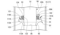
ストッパ部材81は、係合部92よりも当接部91が、ピストンロッド50の軸方向においてロッドガイド28側に位置する。図2に示すように、当接部91は、その軸方向における係合部92とは反対側の端部が当接面93となっている。当接面93は、平面状であり、ピストンロッド50の中心軸線に直交する平面内で広がっている。当接部91は、その当接面93が、ピストンロッド50の軸方向において図1に示すロッドガイド28の端面29と対向する。
The contact portion 91 of the stopper member 81 is located closer to the rod guide 28 than the engaging portion 92 in the axial direction of the piston rod 50 . As shown in FIG. 2 , the contact portion 91 has a contact surface 93 at the end opposite to the engaging portion 92 in the axial direction. The contact surface 93 is planar and spreads within a plane perpendicular to the central axis of the piston rod 50 . The contact surface 93 of the contact portion 91 faces the end face 29 of the rod guide 28 shown in FIG. 1 in the axial direction of the piston rod 50 .
クッション部材82は、第1緩衝部材101(第1部材)と第2緩衝部材102(第2部材)とを有している。
第1緩衝部材101は、弾性部材であり、環状、具体的には円環状に形成されている。第1緩衝部材101は、図2に示すように、外周面部111と内周面部112と端面部113と端面部114とを有している。
外周面部111は円筒面状である。内周面部112は円筒面状である。外周面部111と内周面部112とは同軸状に配置されている。 Thecushion member 82 has a first cushioning member 101 (first member) and a second cushioning member 102 (second member).
Thefirst cushioning member 101 is an elastic member and is formed in an annular shape, specifically an annular shape. The first cushioning member 101 has an outer peripheral surface portion 111, an inner peripheral surface portion 112, an end surface portion 113, and an end surface portion 114, as shown in FIG.
The outerperipheral surface portion 111 is cylindrical. The inner peripheral surface portion 112 is cylindrical. The outer peripheral surface portion 111 and the inner peripheral surface portion 112 are arranged coaxially.
第1緩衝部材101は、弾性部材であり、環状、具体的には円環状に形成されている。第1緩衝部材101は、図2に示すように、外周面部111と内周面部112と端面部113と端面部114とを有している。
外周面部111は円筒面状である。内周面部112は円筒面状である。外周面部111と内周面部112とは同軸状に配置されている。 The
The
The outer
端面部113は平面状である。端面部113は、外周面部111の軸方向の一端縁部から外周面部111の径方向における内方に広がって内周面部112の軸方向の一端縁部に繋がっている。端面部113は、外周面部111および内周面部112の中心軸線に対し直交する平面内で広がっている。端面部114は平面状である。端面部114は、外周面部111の軸方向における端面部113とは反対側の端縁部から外周面部111の径方向における内方に広がって内周面部112の軸方向における端面部113とは反対側の端縁部に繋がっている。端面部114は、外周面部111および内周面部112の中心軸線に対し直交する平面内で広がっている。端面部113および端面部114は、平行である。
The end face portion 113 is planar. The end face portion 113 spreads radially inwardly of the outer peripheral face portion 111 from one axial end edge portion of the outer peripheral face portion 111 and is connected to one axial end edge portion of the inner peripheral face portion 112 . The end surface portion 113 spreads within a plane perpendicular to the central axis of the outer peripheral surface portion 111 and the inner peripheral surface portion 112 . The end face portion 114 is planar. The end surface portion 114 spreads radially inward of the outer peripheral surface portion 111 from the edge portion on the opposite side of the end surface portion 113 in the axial direction of the outer peripheral surface portion 111 and extends axially opposite to the end surface portion 113 of the inner peripheral surface portion 112 . connected to the side edge. The end surface portion 114 spreads within a plane perpendicular to the central axis of the outer peripheral surface portion 111 and the inner peripheral surface portion 112 . The end surface portion 113 and the end surface portion 114 are parallel.
第2緩衝部材102は、弾性部材であり、環状、具体的には円環状に形成されている。第2緩衝部材102は、外周面部121と内周面部122と端面部123と端面部124とを有している。
外周面部121は円筒面状である。内周面部122は円筒面状である。外周面部121の径すなわち第2緩衝部材102の外径は、内周面部112の径すなわち第1緩衝部材101の内径よりも若干大径である。内周面部122の径すなわち第2緩衝部材102の内径は、ピストンロッド50の主軸部51の外周面部53の径すなわち主軸部51の外径よりも若干小径である。外周面部121と内周面部122とは同軸状に配置されている。 Thesecond cushioning member 102 is an elastic member and is formed in an annular shape, specifically an annular shape. The second cushioning member 102 has an outer peripheral surface portion 121 , an inner peripheral surface portion 122 , an end surface portion 123 and an end surface portion 124 .
The outerperipheral surface portion 121 is cylindrical. The inner peripheral surface portion 122 is cylindrical. The diameter of the outer peripheral surface portion 121 , that is, the outer diameter of the second cushioning member 102 is slightly larger than the diameter of the inner peripheral surface portion 112 , that is, the inner diameter of the first cushioning member 101 . The diameter of the inner peripheral surface portion 122 , that is, the inner diameter of the second buffer member 102 is slightly smaller than the diameter of the outer peripheral surface portion 53 of the main shaft portion 51 of the piston rod 50 , that is, the outer diameter of the main shaft portion 51 . The outer peripheral surface portion 121 and the inner peripheral surface portion 122 are arranged coaxially.
外周面部121は円筒面状である。内周面部122は円筒面状である。外周面部121の径すなわち第2緩衝部材102の外径は、内周面部112の径すなわち第1緩衝部材101の内径よりも若干大径である。内周面部122の径すなわち第2緩衝部材102の内径は、ピストンロッド50の主軸部51の外周面部53の径すなわち主軸部51の外径よりも若干小径である。外周面部121と内周面部122とは同軸状に配置されている。 The
The outer
端面部123は平面状である。端面部123は、外周面部121の軸方向の一端縁部から外周面部121の径方向における内方に広がって内周面部122の軸方向の一端縁部に繋がっている。端面部123は、外周面部121および内周面部122の中心軸線に対し直交する平面内で広がっている。端面部124は平面状である。端面部124は、外周面部121の軸方向における端面部123とは反対側の端縁部から外周面部121の径方向における内方に広がって内周面部122の軸方向における端面部123とは反対側の端縁部に繋がっている。端面部124は、外周面部121および内周面部122の中心軸線に対し直交する平面内で広がっている。端面部123および端面部124は、平行である。
The end surface portion 123 is planar. The end face portion 123 spreads radially inwardly of the outer peripheral face portion 121 from one axial end edge portion of the outer peripheral face portion 121 and is connected to one axial end edge portion of the inner peripheral face portion 122 . The end surface portion 123 spreads within a plane perpendicular to the central axis of the outer peripheral surface portion 121 and the inner peripheral surface portion 122 . The end face portion 124 is planar. The end surface portion 124 spreads radially inward of the outer peripheral surface portion 121 from the edge portion on the opposite side of the end surface portion 123 in the axial direction of the outer peripheral surface portion 121 and extends opposite to the end surface portion 123 in the axial direction of the inner peripheral surface portion 122 . connected to the side edge. The end surface portion 124 spreads within a plane perpendicular to the central axis of the outer peripheral surface portion 121 and the inner peripheral surface portion 122 . The end surface portion 123 and the end surface portion 124 are parallel.
第2緩衝部材102の軸方向の長さは、第1緩衝部材101の軸方向の長さよりも長い。言い換えれば、第1緩衝部材101は第2緩衝部材102よりも軸長が小さい。さらに言い換えれば、端面部123,124間の距離は、端面部113,114間の距離よりも大きい。第2緩衝部材102の外径および内径の差は、第1緩衝部材101の外径および内径の差と同等である。言い換えれば、第2緩衝部材102の径方向の厚さは、第1緩衝部材101の径方向の厚さと同等である。
The axial length of the second cushioning member 102 is longer than the axial length of the first cushioning member 101 . In other words, the first cushioning member 101 has a smaller axial length than the second cushioning member 102 . Furthermore, in other words, the distance between end surfaces 123 and 124 is greater than the distance between end surfaces 113 and 114 . The difference between the outer diameter and the inner diameter of the second cushioning member 102 is equivalent to the difference between the outer diameter and the inner diameter of the first cushioning member 101 . In other words, the radial thickness of the second cushioning member 102 is the same as the radial thickness of the first cushioning member 101 .
第2緩衝部材102は、第1緩衝部材101の径方向内側に配置されている。その際に、第2緩衝部材102の外周面部121は全周にわたって第1緩衝部材101の内周面部112に当接している。第2緩衝部材102は、第1緩衝部材101の径方向内側に締め代をもって嵌合されている。これにより、クッション部材82は、第1緩衝部材101と第2緩衝部材102とが同軸状に配置されて一体的に構成されている。第2緩衝部材102の端面部123と、第1緩衝部材101の端面部113とが、第1緩衝部材101および第2緩衝部材102の軸方向における位置を合わせている。これにより、第1緩衝部材101および第2緩衝部材102の軸方向において、第2緩衝部材102の端面部124は、第1緩衝部材101の端面部114よりも、端面部113,123とは反対側に位置する。
The second cushioning member 102 is arranged radially inside the first cushioning member 101 . At that time, the outer peripheral surface portion 121 of the second cushioning member 102 is in contact with the inner peripheral surface portion 112 of the first cushioning member 101 over the entire circumference. The second cushioning member 102 is fitted radially inwardly of the first cushioning member 101 with an interference. Thus, the cushion member 82 is integrally constructed by coaxially arranging the first cushioning member 101 and the second cushioning member 102 . The end surface portion 123 of the second cushioning member 102 and the end surface portion 113 of the first cushioning member 101 are aligned in the axial direction of the first cushioning member 101 and the second cushioning member 102 . As a result, in the axial direction of the first cushioning member 101 and the second cushioning member 102, the end surface portion 124 of the second cushioning member 102 is opposite to the end surface portions 113, 123 rather than the end surface portion 114 of the first cushioning member 101. located on the side.
図1に示すように、クッション部材82は、第1緩衝部材101および第2緩衝部材102が、第2緩衝部材102の径方向の内側にピストンロッド50を挿通させた状態で、ロッドガイド28とストッパ部材81との間に配置される。これにより、第1緩衝部材101および第2緩衝部材102が、ピストンロッド50の軸方向においてピストン45とロッドガイド28との間に設けられる。言い換えれば、第1緩衝部材101および第2緩衝部材102を有するクッション部材82は、ピストン45とロッドガイド28との間に設けられる。その際に、第2緩衝部材102は、ピストンロッド50の主軸部51に締め代をもって嵌合する。言い換えれば、図2に示す内周面部122が主軸部51の外周面部53に圧接する。また、その際に、第1緩衝部材101および第2緩衝部材102は、ピストンロッド50の軸方向において、端面部113および端面部123がストッパ部材81の当接面93と対向し当接する。第1緩衝部材101および第2緩衝部材102は、ピストンロッド50の軸方向において、端面部114および端面部124が図1に示すロッドガイド28の端面29と対向する。なお、第2緩衝部材102は、ピストンロッド50の外周面部53に対し径方向に隙間を有していても良い。
As shown in FIG. 1, the cushion member 82 is configured such that the first cushioning member 101 and the second cushioning member 102 are connected to the rod guide 28 in a state in which the piston rod 50 is inserted radially inwardly of the second cushioning member 102 . It is arranged between the stopper member 81 and the stopper member 81 . Thereby, the first damping member 101 and the second damping member 102 are provided between the piston 45 and the rod guide 28 in the axial direction of the piston rod 50 . In other words, the cushion member 82 having the first cushioning member 101 and the second cushioning member 102 is provided between the piston 45 and the rod guide 28 . At that time, the second buffer member 102 is fitted to the main shaft portion 51 of the piston rod 50 with an interference. In other words, the inner peripheral surface portion 122 shown in FIG. 2 is pressed against the outer peripheral surface portion 53 of the main shaft portion 51 . At this time, the first buffer member 101 and the second buffer member 102 come into contact with the contact surface 93 of the stopper member 81 at the end surface portions 113 and 123 thereof in the axial direction of the piston rod 50 . The first damping member 101 and the second damping member 102 have end surface portions 114 and 124 opposed to the end surface 29 of the rod guide 28 shown in FIG. 1 in the axial direction of the piston rod 50 . In addition, the second buffer member 102 may have a gap in the radial direction with respect to the outer peripheral surface portion 53 of the piston rod 50 .
第1緩衝部材101および第2緩衝部材102を有するクッション部材82は、ピストンロッド50のロッドガイド28およびシール部材41からの伸長によって、ロッドガイド28に当接する。その際に、第1緩衝部材101および第2緩衝部材102は、ロッドガイド28に対し、第1緩衝部材101よりも先に第2緩衝部材102が当接する。具体的には、ピストンロッド50が、ロッドガイド28に対して伸び切り側の第1所定位置に位置すると、ストッパ部材81に当接するクッション部材82のうち、第2緩衝部材102が図2に示す端面部124において図1に示すロッドガイド28の端面29に当接する。ピストンロッド50が、ロッドガイド28に対して第1所定位置よりもさらに伸び切り側に移動すると、第2緩衝部材102が軸方向に圧縮変形する。これにより、ピストンロッド50のロッドガイド28に対する移動速度を抑制する。ピストンロッド50が、ロッドガイド28に対して第1所定位置よりもさらに伸び切り側の第2所定位置に位置すると、クッション部材82のうち、第1緩衝部材101が図2に示す端面部114において図1に示すロッドガイド28の端面29に当接する。ピストンロッド50が、ロッドガイド28に対して第2所定位置よりもさらに伸び切り側に移動すると、第2緩衝部材102および第1緩衝部材101が共に軸方向に圧縮変形する。これにより、ピストンロッド50のロッドガイド28に対する移動速度をさらに抑制する。最終的に、クッション部材82が限界まで軸方向に圧縮変形すると、ピストンロッド50が、ロッドガイド28すなわちシリンダ17に対して停止する。
The cushion member 82 having the first cushioning member 101 and the second cushioning member 102 contacts the rod guide 28 due to the extension of the piston rod 50 from the rod guide 28 and the seal member 41 . At this time, the first buffer member 101 and the second buffer member 102 come into contact with the rod guide 28 before the first buffer member 101 comes into contact with the second buffer member 102 . Specifically, when the piston rod 50 is positioned at the first predetermined position on the fully extended side with respect to the rod guide 28, the second buffer member 102 of the cushion member 82 that abuts against the stopper member 81 is shown in FIG. The end surface portion 124 contacts the end surface 29 of the rod guide 28 shown in FIG. When the piston rod 50 moves further to the fully extended side than the first predetermined position with respect to the rod guide 28, the second cushioning member 102 is compressed and deformed in the axial direction. This suppresses the moving speed of the piston rod 50 with respect to the rod guide 28 . When the piston rod 50 is positioned at the second predetermined position on the extended side further than the first predetermined position with respect to the rod guide 28, the first cushioning member 101 of the cushion member 82 is moved at the end surface portion 114 shown in FIG. It abuts on the end face 29 of the rod guide 28 shown in FIG. When the piston rod 50 moves further to the extended side than the second predetermined position with respect to the rod guide 28, both the second cushioning member 102 and the first cushioning member 101 are compressed and deformed in the axial direction. Thereby, the moving speed of the piston rod 50 with respect to the rod guide 28 is further suppressed. Ultimately, when the cushion member 82 is axially compressed and deformed to its limit, the piston rod 50 stops relative to the rod guide 28 , ie, the cylinder 17 .
このように、ピストンロッド50が、ロッドガイド28に対して伸び切り側の第1所定位置まで移動すると、ロッドガイド28に対し第1緩衝部材101よりも第2緩衝部材102が先に当接し、その後のさらなるピストンロッド50のロッドガイド28に対する伸び切り側への移動で、第2緩衝部材102が軸方向に弾性変形する。その後、ピストンロッド50が、ロッドガイド28に対して第1所定位置よりも伸び切り側の第2所定位置まで移動すると、ロッドガイド28に対し第1緩衝部材101が当接し、その後のさらなるピストンロッド50のロッドガイド28に対する伸び切り側への移動で、第2緩衝部材102および第1緩衝部材101が共に軸方向に弾性変形する。このとき、第1緩衝部材101および第2緩衝部材102は、ロッドガイド28に対し並列に力を作用させる。
Thus, when the piston rod 50 moves to the first predetermined position on the fully extended side with respect to the rod guide 28, the second cushioning member 102 comes into contact with the rod guide 28 earlier than the first cushioning member 101, Further movement of the piston rod 50 to the extension side with respect to the rod guide 28 thereafter elastically deforms the second buffer member 102 in the axial direction. After that, when the piston rod 50 moves to a second predetermined position on the fully extended side of the first predetermined position with respect to the rod guide 28, the first cushioning member 101 abuts against the rod guide 28, and the further piston rod 50 after that comes into contact with the rod guide 28. Movement of 50 to the fully extended side relative to rod guide 28 causes both second cushioning member 102 and first cushioning member 101 to elastically deform in the axial direction. At this time, the first cushioning member 101 and the second cushioning member 102 apply force to the rod guide 28 in parallel.
言い換えれば、シリンダ装置11は、クッション部材82が、2つの第1緩衝部材101および第2緩衝部材102を、ロッドガイド28に対して、並列にたわみ・荷重が作用するよう外周側および内周側に配置している。また、シリンダ装置11は、第1緩衝部材101および第2緩衝部材102の軸方向長を異ならせることで、第1緩衝部材101および第2緩衝部材102のロッドガイド28との当接タイミングを異ならせている。
In other words, the cylinder device 11 is arranged so that the cushion member 82 bends the two first cushioning member 101 and the second cushioning member 102 against the rod guide 28 so that the deflection/load acts in parallel on the outer peripheral side and the inner peripheral side. are placed in In addition, in the cylinder device 11, by making the axial lengths of the first damping member 101 and the second damping member 102 different, the contact timing of the first damping member 101 and the second damping member 102 with the rod guide 28 can be made different. I'm letting
第1緩衝部材101および第2緩衝部材102は、硬度の異なる異材質のクッション材となっている。第2緩衝部材102は、その硬度が、第1緩衝部材101の硬度よりも小さい。これにより、第1緩衝部材101および第2緩衝部材102のうち、軟らかい材質の第2緩衝部材102が、硬い材質の第1緩衝部材101よりも先にロッドガイド28に当接するようになっている。しかも、シリンダ装置11は、クッション部材82が、第1緩衝部材101および第2緩衝部材102のうち、軟らかい材質の第2緩衝部材102を径方向内側、硬い材質の第1緩衝部材101を径方向外側となるよう配置している。
The first cushioning member 101 and the second cushioning member 102 are cushion materials made of different materials with different hardness. The hardness of the second cushioning member 102 is smaller than that of the first cushioning member 101 . As a result, of the first cushioning member 101 and the second cushioning member 102, the second cushioning member 102 made of a soft material comes into contact with the rod guide 28 before the first cushioning member 101 made of a hard material. . Moreover, in the cylinder device 11, the cushion member 82 is arranged so that the second cushioning member 102 made of a soft material is radially inside and the first cushioning member 101 made of a hard material is radially inside the first cushioning member 101 and the second cushioning member 102. It is placed outside.
このように、第1緩衝部材101は、第2緩衝部材102よりも硬度が大きい。第1緩衝部材101は、軸方向の単位変形長さ当たりに受ける荷重が、第2緩衝部材102のそれよりも大きい。第1緩衝部材101は、樹脂からなっている。第1緩衝部材101は、具体的には、PA66(ナイロン66)からなっている。第1緩衝部材101は、PA66以外にも、例えば、PC(ポリカーボネート)、PA6(ナイロン6)、POM(ポリアセタール)、PBT(ポリブチレンテレフタレート)、PPA(ポリフタルアミド)、PPS(ポリフェニレンサルファイド)、PEEK(ポリエーテルエーテルケトン)、PTFE(ポリテトラフルオロエチレン)、PFA(パーフルオロアルコキシアルカン)などや、それらにカーボン系補強材、ガラス繊維などの補強効果のある充填材を含んだものからなっていても良い。第1緩衝部材101は、また例えば、PE(ポリエチレン)系TPEE(熱可塑性エラストマー)、PA(ナイロン)系TPEE、PP(ポリプロピレン)系TPEE、U(ウレタン)系TPEE、CFRP(炭素繊維強化プラスチック)、FKM(フッ化ビニリデン系フッ素ゴム)などや、それらにカーボン系補強材、ガラス繊維などの補強効果のある充填材を含んだものからなっていても良い。
Thus, the first cushioning member 101 has greater hardness than the second cushioning member 102 . The first cushioning member 101 receives a larger load per unit deformation length in the axial direction than the second cushioning member 102 . The first cushioning member 101 is made of resin. Specifically, the first cushioning member 101 is made of PA66 (nylon 66). In addition to PA66, the first cushioning member 101 includes, for example, PC (polycarbonate), PA6 (nylon 6), POM (polyacetal), PBT (polybutylene terephthalate), PPA (polyphthalamide), PPS (polyphenylene sulfide), It consists of PEEK (polyetheretherketone), PTFE (polytetrafluoroethylene), PFA (perfluoroalkoxyalkane), etc., and those containing carbon-based reinforcing materials and fillers with reinforcing effects such as glass fibers. can be The first cushioning member 101 may also be, for example, PE (polyethylene)-based TPEE (thermoplastic elastomer), PA (nylon)-based TPEE, PP (polypropylene)-based TPEE, U (urethane)-based TPEE, CFRP (carbon fiber reinforced plastic). , FKM (vinylidene fluoride-based fluororubber), etc., or those containing a reinforcing filler such as a carbon-based reinforcing material or glass fiber.
第2緩衝部材102は、第1緩衝部材101よりも硬度が小さい。第2緩衝部材102は、軸方向の単位変形長さ当たりに受ける荷重が、第1緩衝部材101のそれよりも小さい。第2緩衝部材102はたわみの大きいエラストマーからなっている。第2緩衝部材102は、具体的には、NBR(ニトリルゴム)からなっている。第2緩衝部材102は、NBR以外にも、例えば、NR(天然ゴム)、IR(合成天然ゴム)、SBR(スチレンブタジエンゴム)、BR(ブタジエンゴム)、CR(クロロプレンゴム)、IIR(ブチルゴム)、EPDM(エチレンプロピレンゴム)、CSM(クロロスルホン化ポリエチレンゴム)、ACM(アクリルゴム)、U(ウレタンゴム)、H-NBR(水素化ニトリルゴム)、VMQ(シリコーンゴム)、FVMQ(フルオロシリコーンゴム)、FKM(フッ素ゴム)、上記ゴムの混合材などや、それらにカーボン系補強材、ガラス繊維などの補強効果のある充填材を含んだものでも良い。第2緩衝部材102は、また例えば、PE系TPEE、PA系TPEE、PP系TPEE、U系TPEEや、それらにカーボン系補強材、ガラス繊維などの補強効果のある充填材を含んだものでも良い。
ここで、第1緩衝部材101と第2緩衝部材102とは、嵌合により一体的に形成するのではなく、成形段階で一体的に形成しても良い。 Thesecond cushioning member 102 has a lower hardness than the first cushioning member 101 . The second cushioning member 102 receives a load per unit deformation length in the axial direction smaller than that of the first cushioning member 101 . The second cushioning member 102 is made of an elastomer with large flexibility. Specifically, the second cushioning member 102 is made of NBR (nitrile rubber). In addition to NBR, the second cushioning member 102 includes, for example, NR (natural rubber), IR (synthetic natural rubber), SBR (styrene butadiene rubber), BR (butadiene rubber), CR (chloroprene rubber), and IIR (butyl rubber). , EPDM (ethylene propylene rubber), CSM (chlorosulfonated polyethylene rubber), ACM (acrylic rubber), U (urethane rubber), H-NBR (hydrogenated nitrile rubber), VMQ (silicone rubber), FVMQ (fluorosilicone rubber) ), FKM (fluororubber), a mixture of the above rubbers, or a material containing a reinforcing filler such as a carbon-based reinforcing material or glass fiber. The second cushioning member 102 may also be, for example, PE-based TPEE, PA-based TPEE, PP-based TPEE, U-based TPEE, or those containing fillers having reinforcing effects such as carbon-based reinforcing materials and glass fibers. .
Here, thefirst cushioning member 101 and the second cushioning member 102 may be integrally formed at the molding stage instead of being integrally formed by fitting.
ここで、第1緩衝部材101と第2緩衝部材102とは、嵌合により一体的に形成するのではなく、成形段階で一体的に形成しても良い。 The
Here, the
クッション部材82は、ピストンロッド50のロッドガイド28およびシール部材41からの伸長によって、ロッドガイド28に当接する。その際に、クッション部材82は、ロッドガイド28に対し第1緩衝部材101よりも第2緩衝部材102が先に当接して軸方向に弾性変形し、その後、ロッドガイド28に対し第1緩衝部材101と第2緩衝部材102とが共に当接して軸方向に弾性変形する。このため、クッション部材82は、第2緩衝部材102がロッドガイド28に当接した後に発生する第1荷重特性よりも、その後、第1緩衝部材101と第2部材とが共にロッドガイド28に当接した後に発生する第2荷重特性の方が、単位変形長さ当たりに受ける荷重が大きい。言い換えれば、クッション部材82は、第2緩衝部材102がロッドガイド28に当接した後に発生する第1荷重特性と、第2緩衝部材102と第1緩衝部材101とがロッドガイド28に当接した後に発生する、第1荷重特性よりも大きな荷重の第2荷重特性と、を有する。
The cushion member 82 abuts against the rod guide 28 due to the extension of the piston rod 50 from the rod guide 28 and the seal member 41 . At this time, the cushion member 82 is elastically deformed in the axial direction when the second cushioning member 102 comes into contact with the rod guide 28 earlier than the first cushioning member 101 , and then the cushion member 82 contacts the rod guide 28 with the first cushioning member 102 . 101 and the second cushioning member 102 are brought into contact with each other and elastically deformed in the axial direction. For this reason, the cushion member 82 is designed so that both the first cushioning member 101 and the second member contact the rod guide 28 after that, rather than the first load characteristic that occurs after the second cushioning member 102 comes into contact with the rod guide 28 . The load received per unit deformation length is greater in the second load characteristic generated after contact. In other words, the cushion member 82 has a first load characteristic generated after the second cushioning member 102 abuts against the rod guide 28 and a load characteristic when the second cushioning member 102 and the first cushioning member 101 abut against the rod guide 28 . a second load characteristic that occurs later and has a greater load than the first load characteristic.
外筒16の開口部24側には、バンパキャップ131が被せられている。バンパキャップ131は、合成樹脂の一体成形品であり、取付部132とカバー部133とを有している。取付部132は円筒状である。カバー部133は、有孔円板状であり、取付部132の軸方向の一端側の端縁部から径方向内方に広がっている。バンパキャップ131は、取付部132が、外筒16の胴部材20にその外周面を覆うように嵌合される。これにより、バンパキャップ131が外筒16に固定される。バンパキャップ131は、カバー部133が、外筒16の開口部24側およびシール部材41を覆う。カバー部133の径方向内側にピストンロッド50が通っている。
The opening 24 side of the outer cylinder 16 is covered with a bumper cap 131 . The bumper cap 131 is an integrally molded product of synthetic resin and has a mounting portion 132 and a cover portion 133 . The mounting portion 132 is cylindrical. The cover portion 133 is in the shape of a perforated disc, and spreads radially inward from the end edge portion of the mounting portion 132 on the one end side in the axial direction. The mounting portion 132 of the bumper cap 131 is fitted to the body member 20 of the outer cylinder 16 so as to cover the outer peripheral surface thereof. Thereby, the bumper cap 131 is fixed to the outer cylinder 16 . The cover portion 133 of the bumper cap 131 covers the opening portion 24 side of the outer cylinder 16 and the seal member 41 . The piston rod 50 passes through the radially inner side of the cover portion 133 .
バンパキャップ131が取り付けられた状態のシリンダ装置11は、ピストンロッド50が車体側に連結され、外筒16に固定された取付アイ25が車輪側に連結される。そして、シリンダ装置11に取り付けられたバンパキャップ131と車体側との間には、弾性樹脂材料からなるバンプラバー141が配置される。バンプラバー141は、蛇腹の筒状をなしており、内側にピストンロッド50の主軸部51を挿通させた状態で車体側に支持される。バンパキャップ131は、そのカバー部133がバンプラバー141に当接することで、バンプラバー141のシール部材41との干渉を防ぐ。
In the cylinder device 11 with the bumper cap 131 attached, the piston rod 50 is connected to the vehicle body side, and the mounting eye 25 fixed to the outer cylinder 16 is connected to the wheel side. A bump rubber 141 made of an elastic resin material is arranged between the bumper cap 131 attached to the cylinder device 11 and the vehicle body. The bump rubber 141 has a bellows tubular shape and is supported by the vehicle body with the main shaft portion 51 of the piston rod 50 inserted therein. The bumper cap 131 prevents the bump rubber 141 from interfering with the seal member 41 by abutting the cover portion 133 on the bump rubber 141 .
上記した特許文献1~3には、ピストンロッドの伸び切り時の衝撃を緩和するクッションを設けたシリンダ装置が記載されている。例えば、特許文献1には、硬度が高いナイロンと、硬度が低いNBRとを直列に繋いだものが開示されている。また、特許文献2には、シリンダ内周へのクッションの噛み込みを防止するため、格納部内にクッションを配置したものが開示されている。また、特許文献3には、クッション内に変形規制部材を収納したものが開示されている。
The above-mentioned Patent Documents 1 to 3 describe a cylinder device provided with a cushion that mitigates the impact when the piston rod is fully extended. For example, Patent Document 1 discloses that nylon having high hardness and NBR having low hardness are connected in series. Further, Japanese Patent Laid-Open No. 2002-200001 discloses a cylinder in which a cushion is arranged in a storage portion in order to prevent the cushion from being caught in the inner periphery of the cylinder. Further, Patent Document 3 discloses a cushion in which a deformation restricting member is accommodated.
ところで、コンパクトな構成でピストンロッドの伸び切り時の衝撃を効果的に緩和することが求められている。衝撃を効果的に緩和するためには、例えば、軸方向の単位変形長さ当たりに受ける荷重が高い高荷重であって、しかも小さな荷重でも大きく撓むことができる高たわみのクッションを設けるのが良い。しかしながら、低剛性の部材のみでクッションを構成すると、形状やサイズを工夫したとしても、大型化してしまう。また、低剛性の部材のみでクッションを構成すると、大きく変形したときに潰れ量が大きく、傷つきやすく、耐久性を満たすことが難しい。他方、高剛性の部材のみでクッションを構成した場合、形状やサイズを工夫したとしても、高たわみの特性を満たすためには、ピストンロッドの軸方向に部材を複数個直列に配置する必要があり、特に軸方向に大型化してしまう。例えば、金属製のコイルスプリングとゴム等の弾性体とを直列に配置すると、大型化してしまう上、異音発生の原因にもなってしまう。よって、いずれにおいても、クッションが大型化してしまい、コンパクトな構成とすることは難しい。その結果、シリンダ径が小さいシリンダ装置や、軸長短縮を求められるシリンダ装置への適用は困難になっている。
By the way, there is a demand for effectively mitigating the impact of the fully extended piston rod with a compact configuration. In order to effectively absorb the impact, for example, it is recommended to provide a high-deflection cushion that receives a high load per unit deformation length in the axial direction and that can flex greatly even with a small load. good. However, if the cushion is composed only of low-rigidity members, even if the shape and size are devised, the size of the cushion increases. In addition, if the cushion is composed only of low-rigidity members, the amount of crushing is large when it is greatly deformed, and it is easily damaged, making it difficult to satisfy durability. On the other hand, if the cushion is composed only of highly rigid members, even if the shape and size are devised, it is necessary to arrange multiple members in series in the axial direction of the piston rod in order to satisfy the high deflection characteristics. , especially in the axial direction. For example, if a coil spring made of metal and an elastic body such as rubber are arranged in series, not only does the size increase, but it also causes abnormal noise. Therefore, in any case, the size of the cushion is increased, and it is difficult to achieve a compact configuration. As a result, it is difficult to apply to a cylinder device with a small cylinder diameter or a cylinder device that requires a shortened shaft length.
第1実施形態のシリンダ装置11は、クッション部材82が、第1緩衝部材101と、第1緩衝部材101の径方向内側にあって、ロッドガイド28に対し第1緩衝部材101よりも先に当接する、第1緩衝部材101よりも硬度が小さい第2緩衝部材102とを有している。そして、クッション部材82は、ロッドガイド28に対し第1緩衝部材101および第2緩衝部材102が並列に力を作用させる。これにより、第1緩衝部材101よりも硬度が小さい第2緩衝部材102が先にロッドガイド28に当接して変形することにより、小さな荷重でも大きく撓むことができる高たわみの特性を得る。そして、その後は、第2緩衝部材102と、これよりも硬度が大きい第1緩衝部材101とがロッドガイド28に対し並列に力を作用させる。これにより、軸方向の単位変形長さ当たりに受ける荷重を高くする高荷重の特性を得る。よって、クッション部材82で衝撃を効果的に緩和することができる。しかも、硬度が小さい部材のみでクッション部材を構成する場合と比べてコンパクトにでき、耐久性も向上できる。また、硬度が大きい部材のみでクッション部材を構成する場合と比べて、部材を複数個直列に配置する必要がないため、コンパクトにできる。さらに、第2緩衝部材102が第1緩衝部材101の径方向内側にあるため、一層コンパクトな構成になり、また安価になる。したがって、コンパクトな構成でピストンロッド50の伸び切り時の衝撃を効果的に緩和することが可能となる。
In the cylinder device 11 of the first embodiment, the cushion member 82 is located radially inward of the first cushioning member 101 and the first cushioning member 101 and contacts the rod guide 28 before the first cushioning member 101. It has a second cushioning member 102 having a lower hardness than the first cushioning member 101 and in contact therewith. In the cushion member 82 , the first cushioning member 101 and the second cushioning member 102 apply force to the rod guide 28 in parallel. As a result, the second cushioning member 102, which has a lower hardness than the first cushioning member 101, comes into contact with the rod guide 28 first and is deformed, thereby obtaining a high deflection characteristic that allows large deflection even with a small load. After that, the second cushioning member 102 and the first cushioning member 101 having greater hardness act on the rod guide 28 in parallel. As a result, a high load characteristic is obtained in which the load received per unit deformation length in the axial direction is increased. Therefore, the cushion member 82 can effectively absorb the impact. Moreover, the cushion member can be made more compact and more durable than the case where the cushion member is composed only of members with low hardness. In addition, compared to the case where the cushion member is composed only of members with high hardness, it is not necessary to arrange a plurality of members in series, so the size can be made compact. Furthermore, since the second cushioning member 102 is located radially inward of the first cushioning member 101, the structure is more compact and the cost is reduced. Therefore, it is possible to effectively mitigate the impact when the piston rod 50 is fully extended with a compact structure.
また、シリンダ装置11は、クッション部材82の第2緩衝部材102がロッドガイド28に当接した後に発生する第1荷重特性と、第2緩衝部材102と第1緩衝部材101とがロッドガイド28に当接した後に発生する、第1荷重特性よりも大きな荷重の第2荷重特性と、を有する。第1荷重特性は、小さな荷重でも大きく撓むことができる高たわみの特性となり、第2荷重特性は、軸方向の単位変形長さ当たりに受ける荷重を高くする高荷重の特性となる。よって、クッション部材82で衝撃を効果的に緩和することができる。しかも、硬度が小さい部材のみでクッション部材を構成する場合と比べてクッション部材をコンパクトにでき、耐久性も向上できる。また、硬度が大きい部材のみでクッション部材を構成する場合と比べて、部材を複数個直列に配置する必要がないため、クッション部材をコンパクトにできる。したがって、コンパクトな構成のクッション部材でピストンロッドの伸び切り時の衝撃を効果的に緩和することが可能となる。
In addition, the cylinder device 11 has a first load characteristic generated after the second buffer member 102 of the cushion member 82 abuts against the rod guide 28 and a a second load characteristic of a greater load than the first load characteristic that occurs after contact. The first load characteristic is a high deflection characteristic that allows large deflection even with a small load, and the second load characteristic is a high load characteristic that increases the load received per unit deformation length in the axial direction. Therefore, the cushion member 82 can effectively absorb the impact. Moreover, the cushion member can be made more compact and its durability can be improved as compared with the case where the cushion member is composed only of members with low hardness. In addition, since there is no need to arrange a plurality of members in series, the cushion member can be made compact as compared with the case where the cushion member is composed only of members having high hardness. Therefore, it is possible to effectively absorb the shock when the piston rod is fully extended with a cushion member having a compact structure.
また、シリンダ装置11は、第1緩衝部材101および第2緩衝部材102がいずれも環状に形成され、第2緩衝部材102は第1緩衝部材101の内周側に配置されている。このため、第1緩衝部材101および第2緩衝部材102のうち、先にロッドガイド28に当接する第2緩衝部材102が大きく潰れても、その径方向外方への変形を第1緩衝部材101が抑制する。また、第2緩衝部材102が膨潤しても、その径方向外方への変形を第1緩衝部材101が抑制する。したがって、シリンダ装置11を特に小径化した場合に、第2緩衝部材102が内筒15に接触してしまうことを抑制できる。その結果、クッション部材82が内筒15に接触しクッション部材82の両側での油液の行き来を阻害して、ピストンロッド50の底部23側への移動を阻害する、いわゆる油圧ロック状態になることを抑制することができる。
Also, in the cylinder device 11 , both the first cushioning member 101 and the second cushioning member 102 are formed in an annular shape, and the second cushioning member 102 is arranged on the inner peripheral side of the first cushioning member 101 . Therefore, even if the second cushioning member 102 that comes into contact with the rod guide 28 first among the first cushioning member 101 and the second cushioning member 102 is greatly crushed, the radially outward deformation is prevented by the first cushioning member 101 . inhibits. Further, even if the second cushioning member 102 swells, the first cushioning member 101 suppresses its radially outward deformation. Therefore, it is possible to prevent the second buffer member 102 from coming into contact with the inner cylinder 15 when the diameter of the cylinder device 11 is reduced. As a result, the cushion member 82 comes into contact with the inner cylinder 15, inhibiting the movement of the oil on both sides of the cushion member 82, and inhibiting the movement of the piston rod 50 toward the bottom portion 23, resulting in a so-called hydraulic lock state. can be suppressed.
また、シリンダ装置11は、第1緩衝部材101が第2緩衝部材102よりも軸長が小さい。このため、容易に、ロッドガイド28に対し第1緩衝部材101よりも先に第2緩衝部材102を当接させることができる。
Also, in the cylinder device 11 , the axial length of the first buffer member 101 is smaller than that of the second buffer member 102 . Therefore, the second cushioning member 102 can be easily brought into contact with the rod guide 28 earlier than the first cushioning member 101 .
また、シリンダ装置11は、第1緩衝部材101と第2緩衝部材102とが一体的に構成されている。このため、ピストンロッド50への取り付けおよび部品管理が容易となる。なお、第1緩衝部材101と第2緩衝部材102とを成形時に一体的に形成することにより、これらを一体化するためだけの工程を省くことができる。
In addition, the cylinder device 11 is configured such that the first damping member 101 and the second damping member 102 are integrally formed. Therefore, attachment to the piston rod 50 and component management are facilitated. By integrally forming the first cushioning member 101 and the second cushioning member 102 at the time of molding, it is possible to omit a process for integrating them.
また、シリンダ装置11は、リバウンドストッパ80が金属製のコイルスプリングをもたないため、異音の発生を抑制することができる。
In addition, since the rebound stopper 80 of the cylinder device 11 does not have a metallic coil spring, it is possible to suppress the generation of abnormal noise.
[第2実施形態]
次に、第2実施形態を主に図4に基づいて第1実施形態との相違部分を中心に説明する。なお、第1実施形態と共通する部位については、同一称呼、同一の符号で表す。
第2実施形態においては、リバウンドストッパ80とは一部異なるリバウンドストッパ80Aがリバウンドストッパ80にかえて設けられている。リバウンドストッパ80Aは、クッション部材82とは一部異なるクッション部材82Aをクッション部材82にかえて有している。クッション部材82Aは、第1緩衝部材101とは一部異なる第1緩衝部材101A(第1部材)を第1緩衝部材101にかえて有している。 [Second embodiment]
Next, the second embodiment will be described mainly based on FIG. 4, focusing on the differences from the first embodiment. Parts common to those of the first embodiment are denoted by the same designations and the same reference numerals.
In the second embodiment, arebound stopper 80</b>A that is partially different from the rebound stopper 80 is provided instead of the rebound stopper 80 . The rebound stopper 80A has a cushion member 82A partially different from the cushion member 82 instead of the cushion member 82. As shown in FIG. The cushion member 82</b>A has a first cushioning member 101</b>A (first member) that is partially different from the first cushioning member 101 instead of the first cushioning member 101 .
次に、第2実施形態を主に図4に基づいて第1実施形態との相違部分を中心に説明する。なお、第1実施形態と共通する部位については、同一称呼、同一の符号で表す。
第2実施形態においては、リバウンドストッパ80とは一部異なるリバウンドストッパ80Aがリバウンドストッパ80にかえて設けられている。リバウンドストッパ80Aは、クッション部材82とは一部異なるクッション部材82Aをクッション部材82にかえて有している。クッション部材82Aは、第1緩衝部材101とは一部異なる第1緩衝部材101A(第1部材)を第1緩衝部材101にかえて有している。 [Second embodiment]
Next, the second embodiment will be described mainly based on FIG. 4, focusing on the differences from the first embodiment. Parts common to those of the first embodiment are denoted by the same designations and the same reference numerals.
In the second embodiment, a
第1緩衝部材101Aは、外周面部111Aと内周面部112Aと端面部113Aと端面部114Aとを有している。外周面部111Aは、外周面部111よりも大径である点が外周面部111とは異なる。内周面部112Aは、内周面部112よりも大径である点が内周面部112とは異なる。端面部113Aは、内径が端面部113よりも大きく、外径が端面部113よりも大きい点が、端面部113とは異なる。端面部114Aは、内径が端面部114よりも大きく、外径が端面部114よりも大きい点が、端面部114とは異なる。
The first cushioning member 101A has an outer peripheral surface portion 111A, an inner peripheral surface portion 112A, an end surface portion 113A, and an end surface portion 114A. The outer peripheral surface portion 111A differs from the outer peripheral surface portion 111 in that it has a larger diameter than the outer peripheral surface portion 111 . The inner peripheral surface portion 112</b>A differs from the inner peripheral surface portion 112 in that it has a larger diameter than the inner peripheral surface portion 112 . The end face portion 113A differs from the end face portion 113 in that its inner diameter is larger than that of the end face portion 113 and its outer diameter is larger than that of the end face portion 113 . The end face portion 114A differs from the end face portion 114 in that its inner diameter is larger than that of the end face portion 114 and its outer diameter is larger than that of the end face portion 114 .
第1緩衝部材101Aの内周面部112Aの径、すなわち第1緩衝部材101Aの内径は、外周面部121の径すなわち第2緩衝部材102の外径よりも大径である。よって、第2緩衝部材102は、第1緩衝部材101Aの径方向内側に配置されると、第1緩衝部材101Aに対して径方向に隙間を設ける。これにより、第2緩衝部材102の変形時以外は、外周面部121の第1緩衝部材101Aの内周面部112Aへの当接部分が、外周面部121の全周にわたることはない。
このようなリバウンドストッパ80Aもピストンロッド50にリバウンドストッパ80と同様に取り付けられてリバウンドストッパ80と同様に作動する。 The diameter of the innerperipheral surface portion 112A of the first cushioning member 101A, that is, the inner diameter of the first cushioning member 101A, is larger than the diameter of the outer peripheral surface portion 121, that is, the outer diameter of the second cushioning member . Therefore, when the second cushioning member 102 is arranged radially inward of the first cushioning member 101A, it provides a radial gap with respect to the first cushioning member 101A. Therefore, except when the second cushioning member 102 is deformed, the contact portion of the outer peripheral surface portion 121 with the inner peripheral surface portion 112A of the first cushioning member 101A does not cover the entire circumference of the outer peripheral surface portion 121 .
Such arebound stopper 80A is also attached to the piston rod 50 in the same manner as the rebound stopper 80 and operates in the same manner as the rebound stopper 80.
このようなリバウンドストッパ80Aもピストンロッド50にリバウンドストッパ80と同様に取り付けられてリバウンドストッパ80と同様に作動する。 The diameter of the inner
Such a
[第3実施形態]
次に、第3実施形態を主に図5に基づいて第1実施形態との相違部分を中心に説明する。なお、第1実施形態と共通する部位については、同一称呼、同一の符号で表す。
第2実施形態においては、リバウンドストッパ80とは一部異なるリバウンドストッパ80Bがリバウンドストッパ80にかえて設けられている。リバウンドストッパ80Bは、クッション部材82とは一部異なるクッション部材82Bをクッション部材82にかえて有している。クッション部材82Bは、第2緩衝部材102とは一部異なる第2緩衝部材102B(第2部材)を第2緩衝部材102にかえて有している。 [Third embodiment]
Next, the third embodiment will be described mainly based on FIG. 5, focusing on the differences from the first embodiment. Parts common to those of the first embodiment are denoted by the same designations and the same reference numerals.
In the second embodiment, arebound stopper 80B that is partially different from the rebound stopper 80 is provided instead of the rebound stopper 80. As shown in FIG. The rebound stopper 80B has a cushion member 82B that is partially different from the cushion member 82 instead of the cushion member 82. As shown in FIG. The cushion member 82B has a second cushioning member 102B (second member) that is partially different from the second cushioning member 102 instead of the second cushioning member 102. As shown in FIG.
次に、第3実施形態を主に図5に基づいて第1実施形態との相違部分を中心に説明する。なお、第1実施形態と共通する部位については、同一称呼、同一の符号で表す。
第2実施形態においては、リバウンドストッパ80とは一部異なるリバウンドストッパ80Bがリバウンドストッパ80にかえて設けられている。リバウンドストッパ80Bは、クッション部材82とは一部異なるクッション部材82Bをクッション部材82にかえて有している。クッション部材82Bは、第2緩衝部材102とは一部異なる第2緩衝部材102B(第2部材)を第2緩衝部材102にかえて有している。 [Third embodiment]
Next, the third embodiment will be described mainly based on FIG. 5, focusing on the differences from the first embodiment. Parts common to those of the first embodiment are denoted by the same designations and the same reference numerals.
In the second embodiment, a
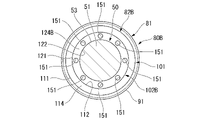
第2緩衝部材102Bには、その径方向における外周面部121と内周面部122との間位置に、第2緩衝部材102Bを軸方向に貫通する貫通孔151が形成されている。第2緩衝部材102Bには、その周方向に等間隔をあけて貫通孔151が複数(具体的には8カ所)形成されている。これにより、第2緩衝部材102Bは、端面部124に対して貫通孔151が開口する点が異なる端面部124Bを有している。また、第2緩衝部材102Bは、図示は略すが、端面部123に対して貫通孔151が開口する点が異なる端面部を有している。
このようなリバウンドストッパ80Bもピストンロッド50にリバウンドストッパ80と同様に取り付けられてリバウンドストッパ80と同様に作動する。
リバウンドストッパ80Bは、貫通孔151が複数形成されているため、硬度がリバウンドストッパ80よりも小さくなり、軸方向の圧縮変形が容易となる。 Thesecond cushioning member 102B has a through hole 151 axially penetrating through the second cushioning member 102B at a position between the outer peripheral surface portion 121 and the inner peripheral surface portion 122 in the radial direction. A plurality of (specifically, eight) through holes 151 are formed in the second cushioning member 102B at equal intervals in the circumferential direction. Thus, the second cushioning member 102B has an end surface portion 124B that is different from the end surface portion 124 in that the through hole 151 is opened. Although not shown, the second cushioning member 102B has an end face portion that is different from the end face portion 123 in that the through hole 151 is opened.
Such arebound stopper 80B is also attached to the piston rod 50 in the same manner as the rebound stopper 80 and operates in the same manner as the rebound stopper 80.
Since a plurality of throughholes 151 are formed in the rebound stopper 80B, the hardness thereof is lower than that of the rebound stopper 80, and compressive deformation in the axial direction is facilitated.
このようなリバウンドストッパ80Bもピストンロッド50にリバウンドストッパ80と同様に取り付けられてリバウンドストッパ80と同様に作動する。
リバウンドストッパ80Bは、貫通孔151が複数形成されているため、硬度がリバウンドストッパ80よりも小さくなり、軸方向の圧縮変形が容易となる。 The
Such a
Since a plurality of through
[第4実施形態]
次に、第4実施形態を主に図6に基づいて第1実施形態との相違部分を中心に説明する。なお、第1実施形態と共通する部位については、同一称呼、同一の符号で表す。
第4実施形態においては、リバウンドストッパ80とは一部異なるリバウンドストッパ80Cがリバウンドストッパ80にかえて設けられている。リバウンドストッパ80Cは、クッション部材82とは一部異なるクッション部材82Cをクッション部材82にかえて有している。クッション部材82Cは、第2緩衝部材102とは一部異なる第2緩衝部材102C(第2部材)を第2緩衝部材102にかえて有している。 [Fourth Embodiment]
Next, the fourth embodiment will be described mainly based on FIG. 6, focusing on the differences from the first embodiment. Parts common to those of the first embodiment are denoted by the same designations and the same reference numerals.
In the fourth embodiment, arebound stopper 80</b>C that is partially different from the rebound stopper 80 is provided instead of the rebound stopper 80 . The rebound stopper 80</b>C has a cushion member 82</b>C that is partially different from the cushion member 82 instead of the cushion member 82 . The cushion member 82C has a second cushioning member 102C (second member) that is partially different from the second cushioning member 102 instead of the second cushioning member 102. As shown in FIG.
次に、第4実施形態を主に図6に基づいて第1実施形態との相違部分を中心に説明する。なお、第1実施形態と共通する部位については、同一称呼、同一の符号で表す。
第4実施形態においては、リバウンドストッパ80とは一部異なるリバウンドストッパ80Cがリバウンドストッパ80にかえて設けられている。リバウンドストッパ80Cは、クッション部材82とは一部異なるクッション部材82Cをクッション部材82にかえて有している。クッション部材82Cは、第2緩衝部材102とは一部異なる第2緩衝部材102C(第2部材)を第2緩衝部材102にかえて有している。 [Fourth Embodiment]
Next, the fourth embodiment will be described mainly based on FIG. 6, focusing on the differences from the first embodiment. Parts common to those of the first embodiment are denoted by the same designations and the same reference numerals.
In the fourth embodiment, a
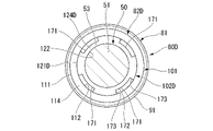
第2緩衝部材102Cには、その径方向の内側部分に溝部161が形成されている。溝部161は、第2緩衝部材102Cの軸方向に延びて第2緩衝部材102Cを軸方向に貫通している。第2緩衝部材102Cには、その周方向に等間隔をあけて溝部161が複数(具体的には4カ所)形成されている。これにより、第2緩衝部材102Cは、内周面部122に対して複数の溝部161で形成される点が異なる内周面部122Cを有している。また、第2緩衝部材102Cは、端面部124に対して溝部161が開口する点が異なる端面部124Cを有している。また、第2緩衝部材102Cは、図示は略すが、端面部123に対して溝部161が開口する点が異なる端面部を有している。
A groove portion 161 is formed in the radially inner portion of the second cushioning member 102C. The groove portion 161 extends in the axial direction of the second cushioning member 102C and penetrates the second cushioning member 102C in the axial direction. A plurality of (specifically, four) grooves 161 are formed at equal intervals in the circumferential direction of the second buffer member 102C. Thereby, the second cushioning member 102C has an inner peripheral surface portion 122C that differs from the inner peripheral surface portion 122 in that it is formed of a plurality of grooves 161 . Further, the second buffer member 102C has an end face portion 124C that differs from the end face portion 124 in that the groove portion 161 opens. Although not shown, the second cushioning member 102C has an end face portion that differs from the end face portion 123 in that the groove portion 161 opens.
溝部161は、平面状の面部162と一対の平面状の面部163とを有している。面部162は、外周面部121の接線方向に沿い且つ外周面部121の軸線方向に沿って広がっている。一対の面部163は、外周面部121の軸線方向に沿って広がっている。一対の面部163は、外周面部121の円周方向における面部162の両端縁部から、外周面部121の中心軸線に向かって広がっている。一対の面部163は、外周面部121の中心軸線に近づくほど互いに外周面部121の円周方向に離れるように広がっている。面部162と一対の平面状の面部163とは、全体として等脚台形の形状をなしている。
The groove portion 161 has a planar surface portion 162 and a pair of planar surface portions 163 . The surface portion 162 extends along the tangential direction of the outer peripheral surface portion 121 and along the axial direction of the outer peripheral surface portion 121 . The pair of surface portions 163 spread along the axial direction of the outer peripheral surface portion 121 . The pair of surface portions 163 spreads from both end edge portions of the surface portion 162 in the circumferential direction of the outer peripheral surface portion 121 toward the center axis of the outer peripheral surface portion 121 . The pair of surface portions 163 widen apart from each other in the circumferential direction of the outer peripheral surface portion 121 as they approach the central axis of the outer peripheral surface portion 121 . The surface portion 162 and the pair of planar surface portions 163 form an isosceles trapezoidal shape as a whole.
このようなリバウンドストッパ80Cもピストンロッド50にリバウンドストッパ80と同様に取り付けられてリバウンドストッパ80と同様に作動する。
リバウンドストッパ80Cは、溝部161が複数形成されているため、硬度がリバウンドストッパ80よりも小さくなり、軸方向の圧縮変形が容易となる。 Such arebound stopper 80</b>C is also attached to the piston rod 50 in the same manner as the rebound stopper 80 and operates in the same manner as the rebound stopper 80 .
Since therebound stopper 80</b>C has a plurality of grooves 161 formed therein, the hardness of the rebound stopper 80</b>C is lower than that of the rebound stopper 80 , and compressive deformation in the axial direction is facilitated.
リバウンドストッパ80Cは、溝部161が複数形成されているため、硬度がリバウンドストッパ80よりも小さくなり、軸方向の圧縮変形が容易となる。 Such a
Since the
[第5実施形態]
次に、第5実施形態を主に図7に基づいて第1実施形態との相違部分を中心に説明する。なお、第1実施形態と共通する部位については、同一称呼、同一の符号で表す。
第5実施形態においては、リバウンドストッパ80とは一部異なるリバウンドストッパ80Dがリバウンドストッパ80にかえて設けられている。リバウンドストッパ80Dは、クッション部材82とは一部異なるクッション部材82Dをクッション部材82にかえて有している。クッション部材82Dは、第2緩衝部材102とは一部異なる第2緩衝部材102D(第2部材)を第2緩衝部材102にかえて有している。 [Fifth embodiment]
Next, the fifth embodiment will be described mainly based on FIG. 7, focusing on the differences from the first embodiment. Parts common to those of the first embodiment are denoted by the same designations and the same reference numerals.
In the fifth embodiment, arebound stopper 80</b>D that is partially different from the rebound stopper 80 is provided instead of the rebound stopper 80 . The rebound stopper 80</b>D has a cushion member 82</b>D that is partially different from the cushion member 82 instead of the cushion member 82 . The cushion member 82</b>D has a second cushioning member 102</b>D (second member) that is partially different from the second cushioning member 102 instead of the second cushioning member 102 .
次に、第5実施形態を主に図7に基づいて第1実施形態との相違部分を中心に説明する。なお、第1実施形態と共通する部位については、同一称呼、同一の符号で表す。
第5実施形態においては、リバウンドストッパ80とは一部異なるリバウンドストッパ80Dがリバウンドストッパ80にかえて設けられている。リバウンドストッパ80Dは、クッション部材82とは一部異なるクッション部材82Dをクッション部材82にかえて有している。クッション部材82Dは、第2緩衝部材102とは一部異なる第2緩衝部材102D(第2部材)を第2緩衝部材102にかえて有している。 [Fifth embodiment]
Next, the fifth embodiment will be described mainly based on FIG. 7, focusing on the differences from the first embodiment. Parts common to those of the first embodiment are denoted by the same designations and the same reference numerals.
In the fifth embodiment, a
第2緩衝部材102Dには、その径方向の外側部分に溝部171が形成されている。溝部171は、第2緩衝部材102Dの軸方向に延び第2緩衝部材102Dを軸方向に貫通している。第2緩衝部材102Dには、その周方向に等間隔をあけて溝部171が複数(具体的には4カ所)形成されている。これにより、第2緩衝部材102Dは、外周面部121に対して溝部171が開口する点が異なる外周面部121Dを有している。また、第2緩衝部材102Dは、端面部124に対して溝部171が開口する点が異なる端面部124Dを有している。また、第2緩衝部材102Dは、図示は略すが、端面部123に対して溝部171が開口する点が異なる端面部を有している。
A groove portion 171 is formed in the radially outer portion of the second cushioning member 102D. The groove portion 171 extends in the axial direction of the second cushioning member 102D and penetrates the second cushioning member 102D in the axial direction. A plurality of (specifically, four) grooves 171 are formed at equal intervals in the circumferential direction of the second cushioning member 102D. Thus, the second cushioning member 102D has an outer peripheral surface portion 121D that differs from the outer peripheral surface portion 121 in that the groove portion 171 opens. Further, the second buffer member 102D has an end surface portion 124D that differs from the end surface portion 124 in that the groove portion 171 opens. Although not shown, the second cushioning member 102D has an end face portion that differs from the end face portion 123 in that the groove portion 171 opens.
溝部171は、円筒面の一部の形状の面部172と一対の平面状の面部173とを有している。面部172は、内周面部122と同軸の円筒面に配置されている。一対の面部173は、内周面部122の円周方向における面部172の両端縁部から、内周面部122の径方向における外側に向かって広がっている。一対の面部173は、内周面部122の径方向に沿い且つ内周面部122の軸方向に沿って広がっている。
The groove portion 171 has a surface portion 172 shaped like a part of a cylindrical surface and a pair of planar surface portions 173 . The surface portion 172 is arranged on a cylindrical surface coaxial with the inner peripheral surface portion 122 . The pair of surface portions 173 spread outward in the radial direction of the inner peripheral surface portion 122 from both end edge portions of the surface portion 172 in the circumferential direction of the inner peripheral surface portion 122 . The pair of surface portions 173 spread along the radial direction of the inner peripheral surface portion 122 and along the axial direction of the inner peripheral surface portion 122 .
このようなリバウンドストッパ80Dもピストンロッド50にリバウンドストッパ80と同様に取り付けられてリバウンドストッパ80と同様に作動する。
リバウンドストッパ80Dは、溝部171が複数形成されているため、硬度がリバウンドストッパ80よりも小さくなり、軸方向の圧縮変形が容易となる。 Such arebound stopper 80</b>D is also attached to the piston rod 50 in the same manner as the rebound stopper 80 and operates in the same manner as the rebound stopper 80 .
Since therebound stopper 80</b>D has a plurality of grooves 171 formed therein, the hardness thereof is lower than that of the rebound stopper 80 , and compressive deformation in the axial direction is facilitated.
リバウンドストッパ80Dは、溝部171が複数形成されているため、硬度がリバウンドストッパ80よりも小さくなり、軸方向の圧縮変形が容易となる。 Such a
Since the
なお、第1~第5実施形態において、ロッドガイド28に対し第1緩衝部材101よりも先に第2緩衝部材102を当接させるための構成として、第1緩衝部材101の軸長を第2緩衝部材102の軸長よりも小さくしたが、これに限らない。例えば、第1緩衝部材101の軸長と第2緩衝部材102の軸長とを同等とし、ロッドガイド28に凹凸を設けても良い。具体的には、ロッドガイド28の端面29の外周側を軸方向に凹ませる。これによっても、ロッドガイド28に対し第1緩衝部材101よりも先に第2緩衝部材102を当接させることができる。
In the first to fifth embodiments, the axial length of the first cushioning member 101 is set to the second length as a configuration for bringing the second cushioning member 102 into contact with the rod guide 28 earlier than the first cushioning member 101. Although it is shorter than the axial length of the cushioning member 102, it is not limited to this. For example, the axial length of the first cushioning member 101 and the axial length of the second cushioning member 102 may be made equal, and the rod guide 28 may be provided with unevenness. Specifically, the outer peripheral side of the end face 29 of the rod guide 28 is recessed in the axial direction. This also allows the second cushioning member 102 to come into contact with the rod guide 28 earlier than the first cushioning member 101 .
また、第1~第5実施形態においては、複筒式のシリンダ装置11を例にとり説明したが、上記構造は単筒式のシリンダ装置にも適用可能である。単筒式のシリンダ装置の場合、例えば、第2室49の第1室48とは反対側にフリーピストンを設け、フリーピストンの第2室49とは反対側にガス室を設けた構造となる。
Also, in the first to fifth embodiments, the double-tube cylinder device 11 was described as an example, but the above structure can also be applied to a single-tube cylinder device. In the case of a mono-cylinder type cylinder device, for example, a free piston is provided on the opposite side of the second chamber 49 from the first chamber 48, and a gas chamber is provided on the opposite side of the free piston from the second chamber 49. .
11…シリンダ装置、17…シリンダ、24…開口部、28…ロッドガイド(閉塞部材)、41…シール部材(閉塞部材)、45…ピストン、50…ピストンロッド、81…ストッパ部材、82,82A~82D…クッション部材、101,101A…第1緩衝部材(第1部材)、102,102B~102D…第2緩衝部材(第2部材)。
11 Cylinder device 17 Cylinder 24 Opening 28 Rod guide (blocking member) 41 Sealing member (blocking member) 45 Piston 50 Piston rod 81 Stopper member 82, 82A~ 82D... Cushion member, 101, 101A... First cushioning member (first member), 102, 102B to 102D... Second cushioning member (second member).
Claims (5)
- 作動流体が封入されるシリンダと、
前記シリンダ内に摺動可能に設けられるピストンと、
前記シリンダの開口部側に設けられる閉塞部材と、
一端側が前記ピストンに連結され他端側が前記閉塞部材に挿通されて前記シリンダの外部まで延出されるピストンロッドと、
前記ピストンと前記閉塞部材との間に設けられ、前記ピストンロッドの伸長によって前記閉塞部材に当接するクッション部材と、
を備え、
前記クッション部材は、
第1部材と、
該第1部材の径方向内側にあって、前記閉塞部材に対し前記第1部材よりも先に当接する、前記第1部材よりも硬度が小さい第2部材と、
を有し、
前記閉塞部材に対し前記第1部材および前記第2部材は並列に力を作用させるシリンダ装置。 a cylinder in which the working fluid is sealed;
a piston slidably provided within the cylinder;
a closing member provided on the opening side of the cylinder;
a piston rod having one end connected to the piston and having the other end inserted through the closing member and extending to the outside of the cylinder;
a cushion member provided between the piston and the closure member, the cushion member abutting against the closure member due to extension of the piston rod;
with
The cushion member is
a first member;
a second member located radially inside the first member and contacting the closing member before the first member, and having a lower hardness than the first member;
has
A cylinder device in which the first member and the second member apply forces in parallel to the closing member. - 作動流体が封入されるシリンダと、
前記シリンダ内に摺動可能に設けられるピストンと、
前記シリンダの開口部側に設けられる閉塞部材と、
一端側が前記ピストンに連結され他端側が前記閉塞部材に挿通されて前記シリンダの外部まで延出されるピストンロッドと、
前記ピストンと前記閉塞部材との間に設けられ、前記ピストンロッドの伸長によって前記閉塞部材に当接するクッション部材と、
を備え、
前記クッション部材は、
第1部材と、
該第1部材よりも硬度が小さい第2部材と、
を有し、
前記第2部材が前記閉塞部材に当接した後に発生する第1荷重特性と、前記第2部材と前記第1部材とが前記閉塞部材に当接した後に発生する、前記第1荷重特性よりも大きな荷重の第2荷重特性と、を有するシリンダ装置。 a cylinder in which the working fluid is sealed;
a piston slidably provided within the cylinder;
a closing member provided on the opening side of the cylinder;
a piston rod having one end connected to the piston and having the other end inserted through the closing member and extending to the outside of the cylinder;
a cushion member provided between the piston and the closure member, the cushion member abutting against the closure member due to extension of the piston rod;
with
The cushion member is
a first member;
a second member having a lower hardness than the first member;
has
A first load characteristic that occurs after the second member abuts against the closure member, and a first load characteristic that occurs after the second member and the first member abut against the closure member. and a second load characteristic of heavy load. - 前記第1部材および前記第2部材は環状に形成され、前記第2部材は前記第1部材の内周側に配置される請求項1または2に記載のシリンダ装置。 The cylinder device according to claim 1 or 2, wherein the first member and the second member are formed in an annular shape, and the second member is arranged on the inner peripheral side of the first member.
- 前記第1部材は前記第2部材よりも軸長が小さい請求項1乃至3の何れか一項に記載のシリンダ装置。 The cylinder device according to any one of claims 1 to 3, wherein the first member has a smaller axial length than the second member.
- 前記第1部材と前記第2部材とは、一体的に形成される請求項1乃至4の何れか一項に記載のシリンダ装置。 The cylinder device according to any one of claims 1 to 4, wherein the first member and the second member are integrally formed.
Priority Applications (3)
| Application Number | Priority Date | Filing Date | Title |
|---|---|---|---|
| KR1020247002862A KR20240023658A (en) | 2021-09-28 | 2022-09-16 | cylinder device |
| CN202280048364.XA CN117642565A (en) | 2021-09-28 | 2022-09-16 | Cylinder device |
| JP2023551320A JPWO2023054007A1 (en) | 2021-09-28 | 2022-09-16 |
Applications Claiming Priority (2)
| Application Number | Priority Date | Filing Date | Title |
|---|---|---|---|
| JP2021157446 | 2021-09-28 | ||
| JP2021-157446 | 2021-09-28 |
Publications (1)
| Publication Number | Publication Date |
|---|---|
| WO2023054007A1 true WO2023054007A1 (en) | 2023-04-06 |
Family
ID=85782504
Family Applications (1)
| Application Number | Title | Priority Date | Filing Date |
|---|---|---|---|
| PCT/JP2022/034686 WO2023054007A1 (en) | 2021-09-28 | 2022-09-16 | Cylinder device |
Country Status (4)
| Country | Link |
|---|---|
| JP (1) | JPWO2023054007A1 (en) |
| KR (1) | KR20240023658A (en) |
| CN (1) | CN117642565A (en) |
| WO (1) | WO2023054007A1 (en) |
Citations (8)
| Publication number | Priority date | Publication date | Assignee | Title |
|---|---|---|---|---|
| JPS6137880Y2 (en) * | 1980-01-19 | 1986-11-01 | ||
| JPS62202543U (en) * | 1986-06-13 | 1987-12-24 | ||
| JPH08233020A (en) * | 1995-02-28 | 1996-09-10 | Kayaba Ind Co Ltd | Structure of cushion at stroke end |
| JPH0914328A (en) * | 1995-06-27 | 1997-01-14 | Kayaba Ind Co Ltd | Rebound cushion device for hydraulic buffer |
| JP2001065511A (en) * | 1999-08-26 | 2001-03-16 | Sakagami Seisakusho Ltd | Buffer ring for cylinder |
| KR20040039649A (en) * | 2002-11-04 | 2004-05-12 | 주식회사 만도 | Stop rubber for use in a shock absorber |
| US20080314707A1 (en) * | 2007-06-20 | 2008-12-25 | Saiman Lun | Damper having a rebound bumper and damper subassembly having same |
| JP2015108414A (en) * | 2013-12-05 | 2015-06-11 | Nok株式会社 | Buffer body |
Family Cites Families (1)
| Publication number | Priority date | Publication date | Assignee | Title |
|---|---|---|---|---|
| JP2006046509A (en) | 2004-08-05 | 2006-02-16 | Kayaba Ind Co Ltd | Hydraulic shock absorber |
-
2022
- 2022-09-16 JP JP2023551320A patent/JPWO2023054007A1/ja active Pending
- 2022-09-16 KR KR1020247002862A patent/KR20240023658A/en active Search and Examination
- 2022-09-16 WO PCT/JP2022/034686 patent/WO2023054007A1/en active Application Filing
- 2022-09-16 CN CN202280048364.XA patent/CN117642565A/en active Pending
Patent Citations (8)
| Publication number | Priority date | Publication date | Assignee | Title |
|---|---|---|---|---|
| JPS6137880Y2 (en) * | 1980-01-19 | 1986-11-01 | ||
| JPS62202543U (en) * | 1986-06-13 | 1987-12-24 | ||
| JPH08233020A (en) * | 1995-02-28 | 1996-09-10 | Kayaba Ind Co Ltd | Structure of cushion at stroke end |
| JPH0914328A (en) * | 1995-06-27 | 1997-01-14 | Kayaba Ind Co Ltd | Rebound cushion device for hydraulic buffer |
| JP2001065511A (en) * | 1999-08-26 | 2001-03-16 | Sakagami Seisakusho Ltd | Buffer ring for cylinder |
| KR20040039649A (en) * | 2002-11-04 | 2004-05-12 | 주식회사 만도 | Stop rubber for use in a shock absorber |
| US20080314707A1 (en) * | 2007-06-20 | 2008-12-25 | Saiman Lun | Damper having a rebound bumper and damper subassembly having same |
| JP2015108414A (en) * | 2013-12-05 | 2015-06-11 | Nok株式会社 | Buffer body |
Also Published As
| Publication number | Publication date |
|---|---|
| KR20240023658A (en) | 2024-02-22 |
| JPWO2023054007A1 (en) | 2023-04-06 |
| CN117642565A (en) | 2024-03-01 |
Similar Documents
| Publication | Publication Date | Title |
|---|---|---|
| US9360078B2 (en) | Hydraulic shock absorber | |
| US10400843B2 (en) | Damper | |
| US6622832B2 (en) | Hydraulic shock absorber | |
| JP7118169B2 (en) | buffer | |
| CN112771284B (en) | Buffer device | |
| WO2023054007A1 (en) | Cylinder device | |
| CN110662906B (en) | Buffer device | |
| JP6072270B2 (en) | Cylinder device and seal member | |
| JP2023064207A (en) | Cylinder device | |
| US7559272B2 (en) | Cylinder apparatus | |
| JP2016188650A (en) | Cylinder device | |
| WO2018092327A1 (en) | Buffer | |
| JP2023004732A (en) | Shock absorber | |
| JP6443985B2 (en) | Cylinder device | |
| JP7285750B2 (en) | buffer | |
| CN111757996B (en) | Reciprocating fluid pressure device | |
| WO2022201760A1 (en) | Shock absorber | |
| JP7450583B2 (en) | buffer | |
| JP2024048444A (en) | Hydraulic shock absorber | |
| JP7154199B2 (en) | buffer | |
| JP2021139439A (en) | Cylinder device | |
| JP6246425B1 (en) | Shock absorber | |
| JP2023173970A (en) | cylinder device | |
| JP2022143217A (en) | Cylinder device | |
| JP2022087446A (en) | Cylinder device |
Legal Events
| Date | Code | Title | Description |
|---|---|---|---|
| 121 | Ep: the epo has been informed by wipo that ep was designated in this application |
Ref document number: 22875878 Country of ref document: EP Kind code of ref document: A1 |
|
| ENP | Entry into the national phase |
Ref document number: 20247002862 Country of ref document: KR Kind code of ref document: A |
|
| WWE | Wipo information: entry into national phase |
Ref document number: 1020247002862 Country of ref document: KR |
|
| WWE | Wipo information: entry into national phase |
Ref document number: 2023551320 Country of ref document: JP |