WO2023053691A1 - 自動分析装置 - Google Patents
自動分析装置 Download PDFInfo
- Publication number
- WO2023053691A1 WO2023053691A1 PCT/JP2022/028341 JP2022028341W WO2023053691A1 WO 2023053691 A1 WO2023053691 A1 WO 2023053691A1 JP 2022028341 W JP2022028341 W JP 2022028341W WO 2023053691 A1 WO2023053691 A1 WO 2023053691A1
- Authority
- WO
- WIPO (PCT)
- Prior art keywords
- temperature
- liquid
- temperature control
- analysis
- automatic
- Prior art date
- Legal status (The legal status is an assumption and is not a legal conclusion. Google has not performed a legal analysis and makes no representation as to the accuracy of the status listed.)
- Ceased
Links
Images





Classifications
-
- G—PHYSICS
- G01—MEASURING; TESTING
- G01N—INVESTIGATING OR ANALYSING MATERIALS BY DETERMINING THEIR CHEMICAL OR PHYSICAL PROPERTIES
- G01N35/00—Automatic analysis not limited to methods or materials provided for in any single one of groups G01N1/00 - G01N33/00; Handling materials therefor
-
- G—PHYSICS
- G01—MEASURING; TESTING
- G01N—INVESTIGATING OR ANALYSING MATERIALS BY DETERMINING THEIR CHEMICAL OR PHYSICAL PROPERTIES
- G01N35/00—Automatic analysis not limited to methods or materials provided for in any single one of groups G01N1/00 - G01N33/00; Handling materials therefor
- G01N35/10—Devices for transferring samples or any liquids to, in, or from, the analysis apparatus, e.g. suction devices, injection devices
- G01N35/1002—Reagent dispensers
-
- G—PHYSICS
- G01—MEASURING; TESTING
- G01N—INVESTIGATING OR ANALYSING MATERIALS BY DETERMINING THEIR CHEMICAL OR PHYSICAL PROPERTIES
- G01N1/00—Sampling; Preparing specimens for investigation
- G01N1/28—Preparing specimens for investigation including physical details of (bio-)chemical methods covered elsewhere, e.g. G01N33/50, C12Q
- G01N1/38—Diluting, dispersing or mixing samples
-
- G—PHYSICS
- G01—MEASURING; TESTING
- G01N—INVESTIGATING OR ANALYSING MATERIALS BY DETERMINING THEIR CHEMICAL OR PHYSICAL PROPERTIES
- G01N35/00—Automatic analysis not limited to methods or materials provided for in any single one of groups G01N1/00 - G01N33/00; Handling materials therefor
- G01N35/08—Automatic analysis not limited to methods or materials provided for in any single one of groups G01N1/00 - G01N33/00; Handling materials therefor using a stream of discrete samples flowing along a tube system, e.g. flow injection analysis
-
- G—PHYSICS
- G01—MEASURING; TESTING
- G01N—INVESTIGATING OR ANALYSING MATERIALS BY DETERMINING THEIR CHEMICAL OR PHYSICAL PROPERTIES
- G01N35/00—Automatic analysis not limited to methods or materials provided for in any single one of groups G01N1/00 - G01N33/00; Handling materials therefor
- G01N2035/00178—Special arrangements of analysers
- G01N2035/00277—Special precautions to avoid contamination (e.g. enclosures, glove- boxes, sealed sample carriers, disposal of contaminated material)
-
- G—PHYSICS
- G01—MEASURING; TESTING
- G01N—INVESTIGATING OR ANALYSING MATERIALS BY DETERMINING THEIR CHEMICAL OR PHYSICAL PROPERTIES
- G01N35/00—Automatic analysis not limited to methods or materials provided for in any single one of groups G01N1/00 - G01N33/00; Handling materials therefor
- G01N2035/00346—Heating or cooling arrangements
- G01N2035/00425—Heating or cooling means associated with pipettes or the like, e.g. for supplying sample/reagent at given temperature
-
- G—PHYSICS
- G01—MEASURING; TESTING
- G01N—INVESTIGATING OR ANALYSING MATERIALS BY DETERMINING THEIR CHEMICAL OR PHYSICAL PROPERTIES
- G01N35/00—Automatic analysis not limited to methods or materials provided for in any single one of groups G01N1/00 - G01N33/00; Handling materials therefor
- G01N35/10—Devices for transferring samples or any liquids to, in, or from, the analysis apparatus, e.g. suction devices, injection devices
- G01N2035/1027—General features of the devices
- G01N2035/1032—Dilution or aliquotting
-
- G—PHYSICS
- G01—MEASURING; TESTING
- G01N—INVESTIGATING OR ANALYSING MATERIALS BY DETERMINING THEIR CHEMICAL OR PHYSICAL PROPERTIES
- G01N35/00—Automatic analysis not limited to methods or materials provided for in any single one of groups G01N1/00 - G01N33/00; Handling materials therefor
- G01N35/10—Devices for transferring samples or any liquids to, in, or from, the analysis apparatus, e.g. suction devices, injection devices
- G01N35/1095—Devices for transferring samples or any liquids to, in, or from, the analysis apparatus, e.g. suction devices, injection devices for supplying the samples to flow-through analysers
Definitions
- the present invention relates to an automatic analyzer.
- Ion-selective electrodes are used in a wide range of fields such as biology, medicine, and the environment because they can quickly quantify the concentration of ions to be measured. Especially in the medical field, there is a close relationship between the metabolic reaction of the body and the ion concentration. It is also used for the diagnosis of kidney disease, neuropathy, etc.
- the concentration of electrolytes in the body is usually maintained within a narrow concentration range, and even a slight change in concentration has a significant meaning.
- ion-selective electrodes are required to have extremely high measurement accuracy, and various technological developments are underway to reduce measurement errors as much as possible. Moreover, in clinical practice, there is a need to continuously analyze a large number of specimens.
- the ion-selective polar method measures the concentration of electrolytes in a sample by measuring the potential difference between an ion-selective electrode and a reference electrode.
- An ion-selective electrode comprises an ion-sensitive membrane that produces a potential difference in response to an ionic component.
- the reference electrode is configured to be in contact with a solution called a reference electrode solution to maintain a reference potential.
- a solution called a reference electrode solution for example, a high-concentration KCl aqueous solution is used.
- a flow cell type device can be formed to achieve high throughput.
- a channel for supplying a sample to be measured is provided inside a housing, and a sensitive membrane is provided in contact with the channel.
- the non-dilution method and the dilution method are known as methods for quantifying the concentration of electrolytes contained in biological samples (blood, especially serum, plasma, urine, etc.).
- a non-dilution method is a method in which a biological sample is measured as it is as a specimen without being diluted.
- a predetermined amount of biological sample is diluted with a predetermined amount of diluent, and the diluted specimen solution (diluted biological sample) is measured using an ion-selective electrode method or the like. be.
- the dilution method requires a small amount of sample solution, the concentration of coexisting substances such as proteins and lipids in the measurement solution is low, and the effect of contamination by coexisting substances is low, so it has high stability in the ion-selective electrode method. is feasible.
- the measurement method that combines the ion-selective electrode method using the flow cell method and the dilution method is currently the mainstream.
- a container called a dilution tank is used to dilute the sample.
- a diluted biological sample prepared in a dilution tank is sent to a flow cell type ion selective electrode through a pipe, and the sample is measured.
- Electrolyte analyzers are generally known to have unstable analytical performance if bacteria propagate in diluted samples. etc.) contain preservatives to prevent bacterial growth. These reagents are used as consumables in flow-type electrolyte analyzers, and are supplied from reagent containers that are individually replaceable.
- the amount used is determined by an arbitrary set value, and as the number of inspection devices and the number of inspections increase, the frequency of replacing reagent bottles increases, increasing the burden on workers.
- the conventional apparatus requires bottle replacement once every several hours during continuous operation, and the apparatus operator is bound by the time schedule for reagent bottle replacement.
- the standard solution in particular is a reagent that serves as the standard for analysis, and minute changes in concentration affect the analytical value, so it is necessary to calibrate each time the bottle is replaced.
- the actual analysis throughput decreases due to the downtime of the device caused by the work caused by the bottle exchange, such as bottle exchange work and subsequent calibration, and the burden on the user increases. rice field.
- One of the countermeasures against the substantial throughput drop described above is to use the pure water available at the customer's facility as the sample diluent, and to adopt a method of diluting the sample with pure water.
- pure water is automatically supplied to the equipment from the piping of the facility, which is effective in reducing the replacement frequency.
- the pure water does not contain preservatives, so unlike when using the above-mentioned dedicated reagents, there is no means to suppress the growth of germs when they occur. Therefore, once bacteria propagate in the flow path inside the device, there is a possibility that the analysis performance will deteriorate. Therefore, the maintenance burden on the operator is increased. On the other hand, if maintenance is emphasized and measures such as ultraviolet sterilization are taken, additional components are required, making the system complicated and expensive.
- an automatic electrolyte analyzer has a temperature sensor and a temperature control mechanism, and it is customary to analyze specimens, reagents, and electrodes in a state where the temperature is controlled at around 30 to 40°C, which is close to the body temperature of the human body. .
- ⁇ a sample temperature control block is provided in a flow path from a sample suction nozzle to an electrode block, and sensors for measuring the temperature of the electrode block, the sample temperature control block, and the outside air are mounted in various places to select ions.
- the output of the heater installed in each block is controlled so that the temperature of the electrode, the reference electrode, the internal solution of the reference electrode, the sample when it reaches each electrode channel, and the calibration solution are the same temperature.
- Patent Document 2 describes a measurement unit that measures the electromotive force of each of a standard solution and a sample solution using an electrode unit having a working electrode and a reference electrode, and a sample solution that is diluted with a diluent to generate a sample solution.
- sample supply means for supplying the sample solution to the dilution tank; diluent supply means for supplying the diluent to the dilution tank; and standard solution supply for supplying the standard solution to the dilution tank means, a measuring solution supplying means for alternately supplying the standard solution and the sample solution from the dilution tank to the electrode part, and a heat provided in the measuring solution supplying means between the dilution tank and the electrode part.
- a replacement part is described.
- a measuring device equipped with a temperature control mechanism for reagents and analysis units is used for analysis in order to ensure analytical performance.
- various bacteria tend to grow in the specimen and reagents, so adding a preservative to the reagent ensures the suppression of the growth of various bacteria in the liquid, which adversely affects analytical performance.
- Patent Documents 1 and 2 do not describe reducing the burden on workers by exchanging reagents to suppress the propagation of bacteria in reagents, nor do they describe countermeasures against lowering analysis throughput due to reagent exchange.
- the present invention has been made in view of the above, and an object of the present invention is to use a temperature control mechanism provided to ensure analytical performance, without adding a complicated structure or work, and appropriately adding pure water.
- a temperature control mechanism provided to ensure analytical performance, without adding a complicated structure or work, and appropriately adding pure water.
- the automatic analyzer comprises an analysis unit that analyzes a sample, a liquid storage unit that stores a liquid used for analysis of the sample, and at least one flow for sending the liquid from the liquid storage unit to the analysis unit. a flow path, a liquid feeding section that feeds the liquid from the liquid storage section to the analysis section through the flow path, and a temperature control section that controls temperatures of the analysis section and the flow path,
- the adjustment unit adjusts the temperature of the analysis unit to a first temperature of 20 to 45°C during the analysis operation, and adjusts the at least one flow path to a temperature of 50 to 90°C after the analysis operation by the analysis unit is completed. The temperature is adjusted to the second temperature.
- FIG. 1 is a diagram showing a schematic configuration of an automatic electrolyte analyzer according to Example 1.
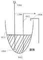
- FIG. 4 is a diagram schematically showing a state in which only the tip portion of the measurement solution suction nozzle is arranged near the deepest part of the dilution tank.
- FIG. 4 is a diagram schematically showing a state in which both the tip portion of the measurement solution suction nozzle and the tip portion of the waste liquid nozzle are arranged in the vicinity of the deepest part of the dilution tank.
- FIG. 4 is a diagram showing a state in which only the tip portion of the waste liquid nozzle is arranged in the vicinity of the deepest part of the dilution tank.
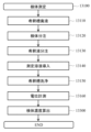
- 4 is a flow chart showing a schematic operation of the automatic electrolyte analyzer according to Example 1.
- FIG. 4 is a flow chart showing an outline of a sample measurement process in Example 1.
- FIG. FIG. 6 is a flow chart showing a part of the flow chart shown in FIG. 5;
- FIG. 1 is a diagram showing a schematic configuration of an automatic electrolyte analyzer 1000 according to the first embodiment.
- an automatic electrolyte analyzer 1000 for measuring the ion concentration contained in a sample includes a dilution tank 1010, a sample dispensing mechanism 1020, a diluent dispensing mechanism 1030, an internal standard solution dispensing mechanism 1040, a liquid sending mechanism 1050, Reference electrode liquid delivery mechanism 1060, flow cell type chloride ion selective electrode (hereinafter referred to as “Cl-ISE”) 1071, flow cell type potassium ion selective electrode (hereinafter referred to as “K-ISE”) 1072, flow cell type It has a sodium ion selective electrode (hereinafter referred to as “Na-ISE”) 1073 , a flow cell type liquid junction 1080 , a flow cell type reference electrode 1090 , a measurement control device 1100 and a dilution tank waste liquid mechanism 1200 .
- Ca-ISE sodium ion selective electrode
- the analysis unit 1092 has a Cl-ISE 1071, a K-ISE 1072, a Na-ISE 1073, a liquid junction 1080 and a reference electrode 1090.
- the first temperature control section 1091 includes an analysis section 1092 that performs ion concentration analysis and a dilution tank 1010 .
- the automatic electrolyte analyzer 1000 includes a sample container 1023 that stores a sample 1021, a diluent 1031, a diluent containing bottle 1032, an internal standard solution 1041, an internal standard solution containing bottle 1042, a reference electrode solution 1061, and a reference electrode.
- Liquid containing bottles 1062 can be installed respectively.
- a waste liquid reservoir 1059 can also be installed in the automatic electrolyte analyzer 1000 .
- the diluent dispensing mechanism 1030 includes a diluent dispensing nozzle 1034, a diluent channel 1033, a second temperature control section 1036 of the diluent channel 1033, and a temperature control mechanism serving as a heat source for the second temperature control section 1036. 1035 and a heat insulating mechanism (heat insulating material) 1037 for insulating the second temperature control section 1036 from the surroundings.
- the heat insulation mechanism 1037 is arranged between the first temperature control section 1091 and the second temperature control section 1036 .
- a channel (not shown) is connected to the diluent dispensing nozzle 1034 .
- the internal standard liquid dispensing mechanism 1040 includes an internal standard liquid dispensing nozzle 1044, an internal standard liquid channel 1043, a second temperature control section 1036, and a temperature control mechanism that serves as a heat source for the second temperature control section 1036. 1035 and a heat insulation mechanism 1037 for insulating the second temperature control section 1036 from the surroundings.
- the second temperature control section 1036 is a metal box that accommodates the diluent channel 1033 and controls the temperature of the diluent channel 1033 with the heat of the temperature control mechanism 1035 .
- a metal box is used, but the second temperature control unit 1036 only needs to transmit the heat of the temperature control mechanism 1035 to the diluent flow channel 1033, and the diluent flow channel 1033 and second temperature control unit 1036 It may be a plate-like structure that contacts with.
- the material is not limited to metal, and any material having high thermal conductivity may be used.
- a channel (not shown) is connected to the diluent dispensing nozzle 1034 .
- the liquid feeding mechanism 1050 includes a measurement solution suction nozzle 1052 and a mechanism (not shown) that drives the measurement solution suction nozzle 1052 in the vertical direction.
- the measurement solution suction nozzle 1052 is connected to the vertical driving mechanism described above.
- a channel (not shown) is connected to the measurement solution suction nozzle 1052 .
- the diluting tank waste liquid mechanism 1200 includes a waste liquid trap 1201, a vacuum pump 1202, an electromagnetic valve 1203, a waste liquid flow path 1204, a waste liquid nozzle 1205 forming the tip of the waste liquid flow path 1204, and a vertical drive mechanism for the waste liquid nozzle 1205. shown).
- a vacuum pump 1202 is located downstream of the waste liquid trap 1201 and introduces into the waste liquid trap 1201 the waste liquid sucked from the waste liquid nozzle 1205 through the open electromagnetic valve 1203 .
- the waste liquid temporarily stored in the waste liquid trap 1201 is transferred to the waste liquid reservoir 1059 by a waste liquid transfer mechanism (not shown).
- the tip of the measurement solution suction nozzle 1052 can be placed near the deepest part 1012 (shown in FIG. 2) of the dilution tank 1010 by a dedicated vertical drive mechanism.
- the tip portion of the waste liquid nozzle 1205 can also be arranged near the deepest portion 1012 of the dilution tank 1010 by a dedicated vertical drive mechanism.
- FIG. 2 schematically shows a state in which only the tip portion of the measurement solution suction nozzle 1052 is arranged near the deepest portion 1012 of the dilution tank 1010 .
- FIG. 3 schematically shows a state in which both the tip portion of the measurement solution suction nozzle 1052 and the tip portion of the waste liquid nozzle 1205 are arranged near the deepest portion 1012 of the dilution tank 1010 .
- FIG. 4 shows a state in which only the tip portion of the waste liquid nozzle 1205 is arranged near the deepest portion 1012 of the dilution tank 1010 .
- the measurement solution suction nozzle 1052 and the waste liquid nozzle 1205 are arranged at positions facing each other across the vertical line that is the rotation axis of the dilution tank 1010 (positions separated by 180°).
- the measuring solution suction nozzle 1052 and the waste liquid nozzle 1205 in the present embodiment 1 are moved up and down parallel to the vertical line by their dedicated vertical drive mechanisms.
- a plurality of flow paths for calibrating liquid or the like may be provided as needed, similar to the second temperature control section 1036 and heat insulation mechanism 1037 .
- the second temperature control unit 1036, the temperature control mechanism 1035, and the heat insulation mechanism 1037 for heat insulation control the temperature of the diluent flow channel 1033 and the internal standard liquid flow channel 1043.
- the second temperature control unit 1036, the temperature control mechanism 1035, and the heat insulation mechanism 1037 for heat insulation may be provided for each of the diluent flow channel 1033 and the internal standard liquid flow channel 1043.
- FIG. 5 is a flow chart showing an outline of the operation performed in the automatic electrolyte analyzer 1000.
- the operations performed in the automatic electrolyte analyzer 1000 are automatically and continuously performed by a program provided in the measurement control device 1100.
- the measurement step 13000 is repeated by the number of samples, and a step of determining whether or not all the samples have been measured.
- a shutdown step 15000 is performed.
- next sample presence/absence determination step 16000 After the shutdown step 15000 is executed, it is determined whether or not there is a next sample by the next sample presence/absence determination step 16000. If it is determined in the next sample presence/absence determination step 16000 that the next sample is present, the process returns to the measurement step 13000 .
- next sample presence/absence determination step 16000 if it is determined that there is no next sample, the shutdown operation 17000 is performed.
- the initialization process 11000 includes preparations such as startup and cleaning of each element mechanism that constitutes the automatic electrolyte analyzer 1000 .
- the measurement control device 1100 sends the reference electrode solution 1061 to the flow cell type liquid junction 1080 via the reference electrode 1090 .
- the measurement control device 1100 dispenses the internal standard solution 1041 into the dilution tank 1010 and sends it to the flow cell liquid junction 1080 via the Cl-ISE 1071, K-ISE 1072 and Na-ISE 1073. Each ISE is conditioned by this liquid feeding.
- the calibration process 12000 includes a low-concentration standard solution measurement process 12100 (not shown), a high-concentration standard solution measurement process 12200 (not shown), a calibration solution measurement process 12300 (not shown), and a calibration curve creation process 12400 (not shown). ) and so on.
- the procedure for measuring the low-concentration standard solution, the high-concentration standard solution, and the calibration solution conforms to the measurement step 13000 described later.
- the standard solution and calibration solution of each concentration are measured in the same manner as the sample, and the electromotive force of each ISE is recorded.
- the measurement control device 1100 obtains the slope sensitivity from the electromotive force measurement results of standard solutions with two different concentrations, high and low.
- the measurement control device 1100 obtains the concentration of the internal standard solution based on the slope sensitivity and the electromotive force of the internal standard solution.
- the measurement control device 1100 also obtains the calculated concentration of the calibration liquid based on the measurement result of the electromotive force of the calibration liquid and the slope sensitivity.
- the measurement control device 1100 obtains an offset correction value based on the difference between the true concentration (display value) of the calibration liquid and the calculated concentration of the calibration liquid.
- the slope sensitivity and offset correction values are called a "calibration curve”.
- the measurement process 13000 mainly consists of a specimen measurement process 13100 , an internal standard solution measurement process 13200 (not shown) and a specimen concentration calculation process 13300 .
- FIG. 6 is a flow chart showing an overview of the sample measurement process 13100.
- the specimen measurement process 13100 includes a dilution tank waste liquid process 13110, a specimen dispensing process 13120, a diluent dispensing process 13130, a measurement solution introduction process 13140, a dilution tank cleaning process 13150, a potential measurement process 13160, and a specimen concentration calculation process. 13300 and the like. Details of each step of the sample measurement step 13100 will be described below.
- the measurement control device 1100 operates the dilution tank waste liquid mechanism 1200 to discharge the liquid inside the dilution tank 1010 (internal standard liquid 1041, dilution liquid 1031, system water (not shown), etc.). do.
- the solenoid valve 1203 is closed until this process is started.
- the solenoid valve 1203 is basically closed in processes other than the dilution tank waste liquid.
- the vacuum pump 1202 operates to evacuate the interior of the drainage channel 1204 and the waste liquid trap 1201 to reduce the pressure.
- the electromagnetic valve 1203 is closed, the pressure inside the waste liquid nozzle 1205 is maintained at atmospheric pressure.
- the measurement control device 1100 drives the vertical drive mechanism (not shown) to immerse the tip of the waste liquid nozzle 1205 in the dilution tank 1010 (see FIG. 4). More specifically, the tip portion of the waste liquid nozzle 1205 is placed at a position approximately 1 mm in the radial direction (horizontal direction) from the deepest portion 1012 of the dilution tank 1010 and 0.5 mm above the surface of the dilution tank 1010 in the vertical direction. .
- the measurement control device 1100 opens the electromagnetic valve 1203 in this state to provide the dilution tank 1010 with a reduced pressure environment through the waste liquid nozzle 1205 .
- the liquid inside the dilution tank 1010 is discharged to the waste liquid trap 1201 through the waste liquid nozzle 1205, the waste liquid flow path 1204, and the solenoid valve 1203.
- the measurement control device 1100 closes the electromagnetic valve 1203 to cut off the pressure reduction.
- the pressure inside the waste liquid nozzle 1205 returns to the atmospheric pressure.
- the measurement control device 1100 drives a vertical drive mechanism (not shown) to position the tip of the waste liquid nozzle 1205 vertically above the dilution tank 1010 (see FIG. 2). That is, the tip portion of the waste liquid nozzle 1205 is moved out of the dilution tank 1010 .
- the measurement control device 1100 uses the sample dispensing mechanism 1020 to suck the sample 1021 into the sample dispensing nozzle 1022 . After that, the measurement control device 1100 brings the tip portion of the sample pipetting nozzle 1022 into contact with the inner wall surface of the dilution tank 1010 to discharge all of the sucked sample 1021 .
- the measurement control device 1100 uses the diluent dispensing mechanism 1030 to dispense the diluent 1031 through the diluent dispensing nozzle 1034 from above the sample 1021 discharged into the dilution tank 1010. It is discharged toward the specimen 1021 .
- the diluent 1031 spirally swirls along the inner surface of the dilution tank 1010, engulfs the specimen 1021, and flows into the inner bottom of the dilution tank 1010.
- the specimen 1021 is diluted with the diluent 1031, and both Mix.
- a diluted sample obtained by diluting the sample 1021 with the diluent 1031 at a predetermined ratio (hereinafter referred to as “dilution ratio”) is obtained in the dilution tank 1010 .
- the dilution ratio is 31 times.
- a diluted sample is a kind of sample solution and is called a “sample solution”.
- the measurement control device 1100 uses a dedicated vertical drive mechanism (not shown) to dip the measurement solution suction nozzle 1052 into the sample solution in the dilution tank 1010 (see FIG. 2). ).
- the vertical drive mechanism basically positions the measurement solution suction nozzle 1052 vertically above the dilution tank 1010 and moves the tip of the measurement solution suction nozzle 1052 out of the dilution tank 1010 . out.
- the measurement control device 1100 interlocks the liquid feeding mechanism 1050 and the reference electrode liquid feeding mechanism 1060 to feed the reference electrode liquid 1061 to the flow cell type liquid junction 1080 via the reference electrode 1090 .
- the measurement control device 1100 sends the sample solution in the dilution tank 1010 as the measurement solution through the Cl-ISE 1071, K-ISE 1072, and Na-ISE 1073 in order to the flow cell liquid junction 1080.
- the measurement solution and the reference electrode liquid 1061 come into contact with each other to form a free flow type liquid junction, and the potential can be measured.
- the measurement control device 1100 discharges the liquid between the flow cell type liquid junction 1080 and the liquid transfer mechanism 1050 to the waste liquid reservoir 1059 .
- the measurement control device 1100 lifts the measurement solution suction nozzle 1052 from the dilution tank 1010 using the vertical drive mechanism for the measurement solution suction nozzle 1052 .
- the measurement control device 1100 first performs the same operation as the dilution tank waste liquid process 13110 described above to drain the sample solution remaining in the dilution tank 1010 .
- the measurement control device 1100 controls the diluent pipetting mechanism 1030 and the internal standard liquid pipetting mechanism 1040, and uses a syringe pump (not shown) connected to the specimen pipetting nozzle 1022 to control a system (not shown).
- Water is dispensed into the dilution tank 1010 through the sample dispensing nozzle 1022 to wash the dilution tank 1010 .
- Diluent 1031 or internal standard 1041 can be dispensed instead of system water.
- the diluent 1031, internal standard liquid 1041, and system water may be dispensed and mixed to clean the dilution tank 1010.
- the measurement control device 1100 measures each electromotive force of the flow cell type Cl-ISE1071, K-ISE1072, and Na-ISE1073 with reference to the reference electrode 1090 using a built-in voltage amplifier, an AD converter, and a microcomputer. etc. to measure and record.
- the specimen concentration calculation step 13300 is executed.
- the measurement control device 1100 calculates the potential measurement process 13160 of the specimen measurement process 13100 and the potential measurement process 13160, which is the internal standard solution measurement process, for the diluted specimen and the internal standard solution in each ISE. Based on the electromotive force difference and the slope sensitivity and dilution ratio (31 times in this Example 1) obtained in the calibration step 12000 (FIG. 5), which is the calibration curve creation step, the concentration ratio between the specimen and the internal standard solution was calculated. demand.
- the measurement control device 1100 multiplies the concentration of the internal standard solution obtained in the calibration step 12000 by this concentration ratio to obtain the concentration of the specimen (before offset correction). By adding the offset correction value to the concentration of the specimen, the measurement control device 1100 obtains the concentration of the specimen (after offset correction).
- the measurement control device 1100 obtains the concentrations of Cl, K, and Na in the sample, and reports the results to the user.
- Steps 14000 and 15000 Returning to the description of FIG. After the measurement step 13000, the measurement control device 1100 executes a step 14000 for determining whether or not all the samples have been measured. Suppression processing 15000 is executed.
- germ suppression processing 15000 which is a pre-startup processing operation, has a constant temperature holding processing step 15001 and a return processing step 15002 to the temperature control state.
- the first temperature control unit 1091 controls the temperature of the analysis unit 1092 and the dilution tank 1010 under the control of the measurement control device 1100 .
- the first temperature control unit 1091 includes a waste liquid nozzle 1205, a diluent dispensing nozzle 1034, a measurement solution suction nozzle 1052, Cl-ISE 1071, K-ISE 1072, Na-ISE 1073, a flow cell type liquid junction 1080, and a flow cell type reference electrode 1090. are maintained at a first temperature (20 to 45° C.), which is a constant temperature range.
- the second temperature control unit 1036 which is thermally separated from the electrode 1090, uses the temperature control mechanism 1035 under the control of the measurement control device 1100 to keep the diluent channel 1033 and the internal standard solution channel 43 constant for a certain period of time. It is held at the second temperature (50° C. to 90° C.), which is the temperature range.
- the liquid in the diluent flow path 1033 and the liquid in the internal standard liquid flow path 1043 are sterilized to suppress the propagation of germs.
- the time required to suppress the growth of bacteria is mainly determined by the set temperature of the temperature control mechanism 1035. For example, at 63°C, 30 minutes is a standard, and the higher the set temperature, the shorter the time required to suppress the growth of bacteria. can.
- the return processing step 15002 includes feeding and discharging the diluent 1031 and the internal standard solution 1041 held in the dilution tank 1010 within a constant temperature range (50 to 90° C.) (FIGS. 2 to 4). ) once (at least part of the liquid used for analysis of the sample is drained by the dilution tank waste liquid mechanism 1200) or multiple times, Cl-ISE 1071, K-ISE 1072, Na-ISE 1073, flow cell type While the liquid junction 1080 and the flow cell type reference electrode 1090 are kept at 20 to 45° C., the temperature control state of the second temperature control unit 1036 is measured. °C).
- a liquid having a temperature equivalent to room temperature is sent to the diluent channel 1033 and the internal standard liquid channel 1043 at least once or more, and the liquid is discharged at least once or more using the dilution tank drainage mechanism 1200.
- a heat exhaust operation is performed to exhaust heat from the diluent storage bottle 1032 and the internal standard fluid storage bottle 1042, which are storage units.
- the second temperature control unit 1036 may include temperature cooling means such as a Peltier element.
- the temperature control state (20 to 45°C) during the measurement step 13000 can be quickly adjusted.
- the measurement process 13000 can be performed without adding cooling means to the diluent liquid flow path 1033 and the internal standard liquid flow path 1043. It is possible to quickly return to the medium temperature control state (20 to 45°C).
- the same operation as in the measurement step 13000 is performed from the waste liquid nozzle 1205 to the dilution tank waste liquid mechanism 1200 at a constant temperature range (50° C.). ⁇ 90°C), when parts with low heat resistance temperature are used for each part such as dilution tank waste liquid mechanism 1200, waste liquid trap 1201, vacuum pump 1202, electromagnetic valve 1203, and waste liquid nozzle 1205. , there is a danger that part or all of the dilution tank waste liquid mechanism 1200, waste liquid trap 1201, vacuum pump 1202, electromagnetic valve 1203, and waste liquid nozzle 1205 will deteriorate.
- a syringe pump (not shown) connected to the specimen dispensing nozzle 1022 is used to dispense system water (not shown) (room temperature) through the specimen dispensing nozzle 1022 into the dilution tank 1010.
- system water not shown
- the liquid discharged from the diluent dispensing nozzle 1034 or the internal standard liquid dispensing nozzle 1044 into the dilution tank 1010 and having a constant temperature range (50° C. to 90° C.) substantially the same as that of the second temperature control unit 1036 is diluted
- the liquid is discharged to the dilution tank waste liquid mechanism 1200 using the waste liquid nozzle 1205 (see FIG. 4).
- Each component of valve 1203 and waste nozzle 1205 can be protected from unnecessary heating.
- the temperature control mechanism 1035 and the heat insulation mechanism 1037 may be thermally separated by separating a physical space, or by using a heat insulating material, the waste liquid nozzle 1205, diluent dispensing nozzle 1034, measurement solution suction nozzle 1052, A state in which physical contact with Cl-ISE 1071, K-ISE 1072, Na-ISE 1073, flow cell type liquid junction 1080, and flow cell type reference electrode 1090 is generated may also be possible.
- the diluent 1031 and internal standard solution 1041 required for measurement are discharged into the dilution tank 1010 in a heated state. , the heat insulation mechanism 1037 is provided, the accuracy of the analysis may be lowered.
- step 14000 even if it is determined that there is no next sample in step 14000 for determining whether or not all samples have been measured, and the shutdown preprocessing operation 15000 is started, additional measurement of the next sample is made in haste due to the circumstances of the analyzer user. may be required to do so. Even in this case, the heating operation of the diluent flow path 1033 and the internal standard liquid flow path 1043 started in the shutdown preprocessing operation 15000 is promptly stopped, and the dilution tank 1010 is kept at a constant temperature range (50 to 90° C) By repeating the feeding and discharging (see FIGS.
- the shutdown operation 17000 of the apparatus is performed to prepare for power shutdown.
- the pre-shutdown processing operation (bacteria suppression processing by heating the flow path) 15000 is automated by specifying the process start time according to the customer's usage status. Support for automation is also possible, such as starting the step 15000 .
- the second temperature control unit 1036 starts heating at an arbitrary time from the state where the temperature is controlled at the first temperature by the first temperature control unit 1091, and the state where the temperature is controlled at the second temperature within a certain period of time. , and the state in which the temperature is controlled at the second temperature is changed to the state in which the temperature is controlled at the first temperature in a short period of time due to the heat exhaust operation described above.
- the heat insulation mechanism 1037 for the second temperature control unit 1036 and the temperature control mechanism 1035 is maintained at 50 to 90° C. in the pre-shutdown operation (bacteria suppression processing by heating the flow path) 15000. It also has a function to prevent a customer from directly touching the temperature control unit 1036 and the temperature control mechanism 1035 and getting burned.
- Example 1 using a temperature control mechanism provided to ensure analytical performance, various bacteria in pure water are appropriately sterilized or sterilized without adding a complicated structure or work, It is possible to provide an automatic analyzer capable of ensuring both analytical performance and reducing the burden on workers.
- Example 2 of the present invention will be described.
- Example 1 the diluent flow path 1033, the internal standard liquid flow path 1043, the liquid in the flow path, and the temperature control state of the second temperature control unit 1036 were changed to the temperature control state (20 to 45°C) during the measurement step 13000.
- the internal standard solution 1041 held in the constant temperature range (50 to 90 ° C.) in the dilution tank 1010 is repeatedly sent and discharged (see FIGS. 2 to 4) once or multiple times.
- Cl-ISE 1071, K-ISE 1072, Na-ISE 1073, flow cell liquid junction 1080, and flow cell reference electrode 1090 are maintained at 20 to 45° C., and the temperature of the second temperature control unit 1036 is changed. It is possible to quickly return the control state to the temperature control state (20 to 45° C.) during the measurement step 13000 and return to the measurement step 13000 in a relatively short time.
- the second temperature control section 1036 is brought into contact with the diluent channel 1033 and the internal standard liquid channel 1043, and the diluent channel 1033 and the internal standard liquid channel 1043 can exchange heat through the second temperature control section 1036. configuration.
- the system water is introduced as the diluent 1032 into the diluent storage bottle 1032, and the system water is automatically replenished in the diluent storage bottle 1032, and the internal standard solution 1041 is neither fed nor discharged. , Only system water is sent and discharged.
- the temperature control state of the second temperature control unit 1036 can be changed to the temperature control state (20 to 45° It is possible to quickly return to C) and return to the measurement step 13000 in a relatively short time.
- the return processing step 15002 can be realized using only system water as the diluent 1032.
- this return processing step 15002 it is possible for the diluent flow path 1033 and the internal standard liquid flow path 1043 to thermally exchange in the second temperature control section 1036, and the internal standard liquid flow path 1043 is also the internal standard liquid. It is possible to quickly return to the temperature control state (20 to 45° C.) during the measurement step 13000 without consuming 1041, and to return to the measurement step 13000 in a relatively short time.
- Liquids that do not have antiseptic ability can be used as system water.
- Example 2 in addition to being able to obtain the same effect as Example 1, it is possible to perform the process of returning to the temperature control state (20 to 45°C) without consuming the internal standard solution.
- the diluent flow channel 1033 and the internal standard liquid flow channel 1043 are configured to exchange heat via the second temperature control unit 1036.
- 1043 can exchange heat, and other configurations may be used as long as they can exchange heat with each other without going through the second temperature control section 1036 .
- At least one of the diluent channel 1033 and the internal standard liquid channel 1043 is configured to be temperature-controlled to a second temperature of 50°C to 90°C. It is also possible to Also, the first temperature control section 1091 and the second temperature control section 1036 are collectively referred to as a temperature control section. Therefore, the temperature control section includes the first temperature control section 1091 and the second temperature control section 1036 . The first temperature control section 1091 and the second temperature control section 1036 can perform temperature control operations independently of each other.
- the above example is an example in which the present invention is applied to an automatic electrolyte analyzer, but the present invention can be applied to other automatic analyzers.
Landscapes
- Physics & Mathematics (AREA)
- Health & Medical Sciences (AREA)
- Life Sciences & Earth Sciences (AREA)
- Chemical & Material Sciences (AREA)
- Analytical Chemistry (AREA)
- Biochemistry (AREA)
- General Health & Medical Sciences (AREA)
- General Physics & Mathematics (AREA)
- Immunology (AREA)
- Pathology (AREA)
- Automatic Analysis And Handling Materials Therefor (AREA)
Priority Applications (4)
| Application Number | Priority Date | Filing Date | Title |
|---|---|---|---|
| CN202280059559.4A CN117940775A (zh) | 2021-09-30 | 2022-07-21 | 自动分析装置 |
| JP2023550409A JP7660212B2 (ja) | 2021-09-30 | 2022-07-21 | 自動分析装置 |
| US18/695,964 US20250004003A1 (en) | 2021-09-30 | 2022-07-21 | Automatic analyzer |
| EP22875568.2A EP4411380A4 (en) | 2021-09-30 | 2022-07-21 | AUTOMATIC ANALYZER |
Applications Claiming Priority (2)
| Application Number | Priority Date | Filing Date | Title |
|---|---|---|---|
| JP2021161042 | 2021-09-30 | ||
| JP2021-161042 | 2021-09-30 |
Publications (1)
| Publication Number | Publication Date |
|---|---|
| WO2023053691A1 true WO2023053691A1 (ja) | 2023-04-06 |
Family
ID=85782234
Family Applications (1)
| Application Number | Title | Priority Date | Filing Date |
|---|---|---|---|
| PCT/JP2022/028341 Ceased WO2023053691A1 (ja) | 2021-09-30 | 2022-07-21 | 自動分析装置 |
Country Status (5)
| Country | Link |
|---|---|
| US (1) | US20250004003A1 (https=) |
| EP (1) | EP4411380A4 (https=) |
| JP (1) | JP7660212B2 (https=) |
| CN (1) | CN117940775A (https=) |
| WO (1) | WO2023053691A1 (https=) |
Cited By (2)
| Publication number | Priority date | Publication date | Assignee | Title |
|---|---|---|---|---|
| WO2024075383A1 (ja) * | 2022-10-06 | 2024-04-11 | 株式会社日立ハイテク | 自動分析装置および自動分析装置の運転方法 |
| WO2026042388A1 (ja) * | 2024-08-22 | 2026-02-26 | 株式会社日立ハイテク | 自動分析装置 |
Citations (8)
| Publication number | Priority date | Publication date | Assignee | Title |
|---|---|---|---|---|
| JP2007093252A (ja) | 2005-09-27 | 2007-04-12 | Jokoh Co Ltd | 電解質分析装置の温調システム |
| JP2012181102A (ja) | 2011-03-01 | 2012-09-20 | Jeol Ltd | 電解質測定装置 |
| JP2017146182A (ja) * | 2016-02-17 | 2017-08-24 | 株式会社日立ハイテクノロジーズ | 自動分析装置及びその洗浄方法 |
| JP2018036080A (ja) * | 2016-08-30 | 2018-03-08 | 株式会社日立ハイテクノロジーズ | 自動分析装置 |
| JP2018146374A (ja) * | 2017-03-06 | 2018-09-20 | テラメックス株式会社 | 温調システム |
| JP2019074311A (ja) * | 2016-02-19 | 2019-05-16 | 株式会社日立ハイテクノロジーズ | 自動分析装置および分注プローブの洗浄方法 |
| JP2020041875A (ja) * | 2018-09-10 | 2020-03-19 | 株式会社日立ハイテクノロジーズ | 自動分析装置 |
| JP2020106424A (ja) * | 2018-12-27 | 2020-07-09 | 株式会社日立ハイテク | 自動分析装置 |
Family Cites Families (9)
| Publication number | Priority date | Publication date | Assignee | Title |
|---|---|---|---|---|
| JPS6087887A (ja) * | 1983-10-19 | 1985-05-17 | Shinwa Control Kk | 流水システムの配管系及びその滅菌法 |
| JP4620551B2 (ja) * | 2005-08-24 | 2011-01-26 | 株式会社日立ハイテクノロジーズ | 電解質測定装置 |
| DE102009029305A1 (de) * | 2009-09-09 | 2011-03-10 | Endress + Hauser Conducta Gesellschaft für Mess- und Regeltechnik mbH + Co. KG | Analysegerät zur automatisierten Bestimmung einer Messgröße einer Flüssigkeitsprobe |
| DE102011007011B4 (de) * | 2011-04-07 | 2024-02-01 | Endress+Hauser Conducta Gmbh+Co. Kg | Analysegerät zur automatisierten Bestimmung einer Messgröße einer Flüssigkeitsprobe und Verfahren zur Überwachung einer Messgröße |
| CN113287022B (zh) * | 2018-12-27 | 2023-12-12 | 株式会社日立高新技术 | 自动分析装置、自动分析系统及样品的自动分析方法 |
| EP4040158A4 (en) * | 2019-07-22 | 2023-12-06 | Hitachi High-Tech Corporation | Automatic analysis device and method of automatic sample analysis |
| CN115004020B (zh) * | 2020-01-29 | 2024-08-27 | 株式会社日立高新技术 | 电解质分析装置 |
| EP4105651B1 (en) * | 2020-02-14 | 2025-08-13 | Hitachi High-Tech Corporation | Electrolyte analysis apparatus |
| JP7231576B2 (ja) * | 2020-03-09 | 2023-03-01 | 株式会社日立ハイテク | 電解質濃度測定装置 |
-
2022
- 2022-07-21 WO PCT/JP2022/028341 patent/WO2023053691A1/ja not_active Ceased
- 2022-07-21 CN CN202280059559.4A patent/CN117940775A/zh active Pending
- 2022-07-21 US US18/695,964 patent/US20250004003A1/en active Pending
- 2022-07-21 EP EP22875568.2A patent/EP4411380A4/en active Pending
- 2022-07-21 JP JP2023550409A patent/JP7660212B2/ja active Active
Patent Citations (8)
| Publication number | Priority date | Publication date | Assignee | Title |
|---|---|---|---|---|
| JP2007093252A (ja) | 2005-09-27 | 2007-04-12 | Jokoh Co Ltd | 電解質分析装置の温調システム |
| JP2012181102A (ja) | 2011-03-01 | 2012-09-20 | Jeol Ltd | 電解質測定装置 |
| JP2017146182A (ja) * | 2016-02-17 | 2017-08-24 | 株式会社日立ハイテクノロジーズ | 自動分析装置及びその洗浄方法 |
| JP2019074311A (ja) * | 2016-02-19 | 2019-05-16 | 株式会社日立ハイテクノロジーズ | 自動分析装置および分注プローブの洗浄方法 |
| JP2018036080A (ja) * | 2016-08-30 | 2018-03-08 | 株式会社日立ハイテクノロジーズ | 自動分析装置 |
| JP2018146374A (ja) * | 2017-03-06 | 2018-09-20 | テラメックス株式会社 | 温調システム |
| JP2020041875A (ja) * | 2018-09-10 | 2020-03-19 | 株式会社日立ハイテクノロジーズ | 自動分析装置 |
| JP2020106424A (ja) * | 2018-12-27 | 2020-07-09 | 株式会社日立ハイテク | 自動分析装置 |
Non-Patent Citations (1)
| Title |
|---|
| See also references of EP4411380A4 |
Cited By (4)
| Publication number | Priority date | Publication date | Assignee | Title |
|---|---|---|---|---|
| WO2024075383A1 (ja) * | 2022-10-06 | 2024-04-11 | 株式会社日立ハイテク | 自動分析装置および自動分析装置の運転方法 |
| JPWO2024075383A1 (https=) * | 2022-10-06 | 2024-04-11 | ||
| JP7821899B2 (ja) | 2022-10-06 | 2026-02-27 | 株式会社日立ハイテク | 自動分析装置および自動分析装置の運転方法 |
| WO2026042388A1 (ja) * | 2024-08-22 | 2026-02-26 | 株式会社日立ハイテク | 自動分析装置 |
Also Published As
| Publication number | Publication date |
|---|---|
| CN117940775A (zh) | 2024-04-26 |
| US20250004003A1 (en) | 2025-01-02 |
| EP4411380A4 (en) | 2025-08-06 |
| JPWO2023053691A1 (https=) | 2023-04-06 |
| JP7660212B2 (ja) | 2025-04-10 |
| EP4411380A1 (en) | 2024-08-07 |
Similar Documents
| Publication | Publication Date | Title |
|---|---|---|
| US10768136B2 (en) | Electrolyte concentration measurement device | |
| US8647592B2 (en) | Method for transport of suspensions containing mechanically sensitive material | |
| WO2023053691A1 (ja) | 自動分析装置 | |
| EP2479560A1 (en) | Automatic analyzing device | |
| US12055484B2 (en) | Computer-implemented method and system for spectroscopic analysis of biological material | |
| WO2018135048A1 (ja) | 自動分析装置、自動分析装置における廃液方法、及び、三方電磁弁 | |
| JP6126387B2 (ja) | 二重管構造試料吸引ノズルを備えた電解質分析装置 | |
| US12332209B2 (en) | Electrolyte analysis device | |
| JP7492540B2 (ja) | 電解質分析装置 | |
| JP5492833B2 (ja) | 自動分析装置およびその制御方法 | |
| JP7821899B2 (ja) | 自動分析装置および自動分析装置の運転方法 | |
| JP7391224B2 (ja) | 電解質分析装置 | |
| US20170227565A1 (en) | Method for operating an automated analysis machine | |
| CN117616283A (zh) | 自动分析装置以及自动分析装置的试剂管理方法 | |
| US20250154447A1 (en) | Measurement System and Method for in Situ Calibration | |
| WO2025220386A1 (ja) | 電解質分析装置、制御方法 | |
| WO2024154436A1 (ja) | 分析装置、および分析装置の流路の共洗い方法 | |
| CN114127550A (zh) | 脱气装置及电解质测量系统 | |
| JP6671213B2 (ja) | 自動分析装置および自動分析方法 | |
| WO2025225258A1 (ja) | 分析装置 |
Legal Events
| Date | Code | Title | Description |
|---|---|---|---|
| 121 | Ep: the epo has been informed by wipo that ep was designated in this application |
Ref document number: 22875568 Country of ref document: EP Kind code of ref document: A1 |
|
| WWE | Wipo information: entry into national phase |
Ref document number: 2023550409 Country of ref document: JP |
|
| WWE | Wipo information: entry into national phase |
Ref document number: 202280059559.4 Country of ref document: CN |
|
| WWE | Wipo information: entry into national phase |
Ref document number: 18695964 Country of ref document: US |
|
| NENP | Non-entry into the national phase |
Ref country code: DE |
|
| ENP | Entry into the national phase |
Ref document number: 2022875568 Country of ref document: EP Effective date: 20240430 |