WO2023053245A1 - ガイドワイヤ - Google Patents
ガイドワイヤ Download PDFInfo
- Publication number
- WO2023053245A1 WO2023053245A1 PCT/JP2021/035773 JP2021035773W WO2023053245A1 WO 2023053245 A1 WO2023053245 A1 WO 2023053245A1 JP 2021035773 W JP2021035773 W JP 2021035773W WO 2023053245 A1 WO2023053245 A1 WO 2023053245A1
- Authority
- WO
- WIPO (PCT)
- Prior art keywords
- guide wire
- guidewire
- core shaft
- main body
- rear end
- Prior art date
- Legal status (The legal status is an assumption and is not a legal conclusion. Google has not performed a legal analysis and makes no representation as to the accuracy of the status listed.)
- Ceased
Links
Images








Classifications
-
- A—HUMAN NECESSITIES
- A61—MEDICAL OR VETERINARY SCIENCE; HYGIENE
- A61B—DIAGNOSIS; SURGERY; IDENTIFICATION
- A61B17/00—Surgical instruments, devices or methods
- A61B17/22—Implements for squeezing-off ulcers or the like on inner organs of the body; Implements for scraping-out cavities of body organs, e.g. bones; for invasive removal or destruction of calculus using mechanical vibrations; for removing obstructions in blood vessels, not otherwise provided for
-
- A—HUMAN NECESSITIES
- A61—MEDICAL OR VETERINARY SCIENCE; HYGIENE
- A61M—DEVICES FOR INTRODUCING MEDIA INTO, OR ONTO, THE BODY; DEVICES FOR TRANSDUCING BODY MEDIA OR FOR TAKING MEDIA FROM THE BODY; DEVICES FOR PRODUCING OR ENDING SLEEP OR STUPOR
- A61M25/00—Catheters; Hollow probes
- A61M25/01—Introducing, guiding, advancing, emplacing or holding catheters
- A61M25/09—Guide wires
-
- A—HUMAN NECESSITIES
- A61—MEDICAL OR VETERINARY SCIENCE; HYGIENE
- A61B—DIAGNOSIS; SURGERY; IDENTIFICATION
- A61B17/00—Surgical instruments, devices or methods
- A61B17/00234—Surgical instruments, devices or methods for minimally invasive surgery
-
- A—HUMAN NECESSITIES
- A61—MEDICAL OR VETERINARY SCIENCE; HYGIENE
- A61B—DIAGNOSIS; SURGERY; IDENTIFICATION
- A61B17/00—Surgical instruments, devices or methods
- A61B17/00234—Surgical instruments, devices or methods for minimally invasive surgery
- A61B2017/00238—Type of minimally invasive operation
-
- A—HUMAN NECESSITIES
- A61—MEDICAL OR VETERINARY SCIENCE; HYGIENE
- A61B—DIAGNOSIS; SURGERY; IDENTIFICATION
- A61B17/00—Surgical instruments, devices or methods
- A61B17/22—Implements for squeezing-off ulcers or the like on inner organs of the body; Implements for scraping-out cavities of body organs, e.g. bones; for invasive removal or destruction of calculus using mechanical vibrations; for removing obstructions in blood vessels, not otherwise provided for
- A61B2017/22038—Implements for squeezing-off ulcers or the like on inner organs of the body; Implements for scraping-out cavities of body organs, e.g. bones; for invasive removal or destruction of calculus using mechanical vibrations; for removing obstructions in blood vessels, not otherwise provided for with a guide wire
- A61B2017/22042—Details of the tip of the guide wire
-
- A—HUMAN NECESSITIES
- A61—MEDICAL OR VETERINARY SCIENCE; HYGIENE
- A61M—DEVICES FOR INTRODUCING MEDIA INTO, OR ONTO, THE BODY; DEVICES FOR TRANSDUCING BODY MEDIA OR FOR TAKING MEDIA FROM THE BODY; DEVICES FOR PRODUCING OR ENDING SLEEP OR STUPOR
- A61M25/00—Catheters; Hollow probes
- A61M25/01—Introducing, guiding, advancing, emplacing or holding catheters
- A61M25/09—Guide wires
- A61M2025/09058—Basic structures of guide wires
- A61M2025/09083—Basic structures of guide wires having a coil around a core
-
- A—HUMAN NECESSITIES
- A61—MEDICAL OR VETERINARY SCIENCE; HYGIENE
- A61M—DEVICES FOR INTRODUCING MEDIA INTO, OR ONTO, THE BODY; DEVICES FOR TRANSDUCING BODY MEDIA OR FOR TAKING MEDIA FROM THE BODY; DEVICES FOR PRODUCING OR ENDING SLEEP OR STUPOR
- A61M25/00—Catheters; Hollow probes
- A61M25/01—Introducing, guiding, advancing, emplacing or holding catheters
- A61M25/09—Guide wires
- A61M2025/09133—Guide wires having specific material compositions or coatings; Materials with specific mechanical behaviours, e.g. stiffness, strength to transmit torque
-
- A—HUMAN NECESSITIES
- A61—MEDICAL OR VETERINARY SCIENCE; HYGIENE
- A61M—DEVICES FOR INTRODUCING MEDIA INTO, OR ONTO, THE BODY; DEVICES FOR TRANSDUCING BODY MEDIA OR FOR TAKING MEDIA FROM THE BODY; DEVICES FOR PRODUCING OR ENDING SLEEP OR STUPOR
- A61M25/00—Catheters; Hollow probes
- A61M25/01—Introducing, guiding, advancing, emplacing or holding catheters
- A61M25/09—Guide wires
- A61M2025/0915—Guide wires having features for changing the stiffness
-
- A—HUMAN NECESSITIES
- A61—MEDICAL OR VETERINARY SCIENCE; HYGIENE
- A61M—DEVICES FOR INTRODUCING MEDIA INTO, OR ONTO, THE BODY; DEVICES FOR TRANSDUCING BODY MEDIA OR FOR TAKING MEDIA FROM THE BODY; DEVICES FOR PRODUCING OR ENDING SLEEP OR STUPOR
- A61M25/00—Catheters; Hollow probes
- A61M25/01—Introducing, guiding, advancing, emplacing or holding catheters
- A61M25/09—Guide wires
- A61M2025/09175—Guide wires having specific characteristics at the distal tip
Definitions
- the present invention relates to guidewires.
- a guide wire is conventionally known as a medical device that is used by percutaneously inserting it into a blood vessel in order to treat a stenosis that has occurred in the blood vessel.
- Patent Literature 1 describes a guide wire used for treatment of lower extremity blood vessels.
- FIG. 26 is an explanatory diagram illustrating blood vessels of the lower extremities of the human body.
- FIG. 27 is an explanatory diagram exemplifying the X area in FIG. 26 in an enlarged manner.
- the guide wire 1 is inserted into the blood vessel from the puncture site 101 near the thigh of the leg other than the leg having the stenosis Le, and passes through the common iliac artery (hereinafter referred to as the CIA).
- the leg is moved to the leg on which the constricted portion Le exists, and the leg is reached to the constricted portion Le.
- FIG. 26 illustrates a state in which the guide wire 1 is inserted into the blood vessels of the lower extremities of the human body.
- a stenosed portion Le occurs in the anterior tibial artery (hereinafter referred to as ATA) included in the below-the-knee area (hereinafter referred to as BK area).
- the guide wire 1 is first percutaneously inserted into a blood vessel in the body from a puncture site 101 near the thigh of the leg other than the leg where the constriction Le occurs.
- the guide wire 1 advances through the CIA toward the abdominal aorta (hereinafter referred to as AA), passes through the curved portion 100 of the CIA, and further advances through the CIA toward the constricted portion Le.
- AA abdominal aorta
- the guidewire 1 is used for the external iliac artery (hereinafter referred to as EIA), common femoral artery (hereinafter referred to as CFA), superficial femoral artery (hereinafter referred to as SFA) and popliteal artery (hereinafter referred to as Pop.A ) to reach the anterior tibial artery (ATA).
- EIA external iliac artery
- CFA common femoral artery
- SFA superficial femoral artery
- Pop.A popliteal artery
- the guidewire 1 is left in the vicinity of the stenosis Le, and a combined instrument such as a catheter is inserted into the blood vessel along the guidewire 1 to treat the stenosis Le.
- a combined instrument such as a catheter is inserted into the blood vessel along the guidewire 1 to treat the stenosis Le.
- the guidewire passes through the CIA, EIA, and CFA, which are relatively curved even in the blood vessels of the lower
- transmission performance transmission performance
- delivery performance improvement in the performance for allowing a combined instrument such as a catheter inserted into a blood vessel along a guide wire to pass through the CIA, which has a particularly large degree of curvature.
- the present invention has been made in order to solve the above-described problems.
- An object is to provide a guide wire that is excellent in both.
- the present invention has been made to solve at least part of the above problems, and can be implemented as the following forms.
- a guidewire is provided.
- This guide wire has a core shaft, the main body of which is 350 mm or more and 750 mm or less from the tip is made of a nickel-titanium alloy, and the main body has an outer diameter of 0.58 mm or more and 0.73 mm or less. be.
- the main body which is a portion of 350 mm or more and 750 mm or less from the tip of the core shaft, is made of a nickel-titanium alloy and has an outer diameter of 0.58 mm or more and 0.73 mm or less. It is possible to provide a guide wire that is excellent in both torque transmission performance during treatment by the crossover method and delivery performance. Specifically, since the main body is made of a nickel-titanium alloy, even when the main body passes through CIA, EIA, and CFA, which have a large degree of curvature, the operability due to the deformation of the core shaft is improved by the crossover method. Exacerbation can be reduced.
- the main body has an outer diameter of 0.58 mm or more, by placing the main body in the vicinity of the CIA, a combined instrument such as a catheter can be easily advanced from one leg to the other along the guide wire. be able to.
- the main body is 0.73 mm or less, the rotating operation of the operator can be efficiently transmitted to the distal end of the guide wire by arranging the main body near the CIA.
- the main body is in the range of 350 mm or more and 750 mm or less from the tip of the core shaft, the main body can be placed near the CIA regardless of the length of the patient's blood vessel, and torque transmission of the guide wire Performance and delivery performance can be improved in more patients.
- the outer diameter of the main body of the core shaft may be 0.71 mm or less.
- the torque transmission performance during treatment by the crossover method can be further improved. can be planned.
- the present invention can be implemented in various aspects, for example, in the form of a guidewire, a guidewire manufacturing method, a catheter manufacturing method, an endoscope, a dilator, and the like.
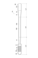
- FIG. 1 is an explanatory diagram illustrating the overall configuration of a guidewire according to a first embodiment
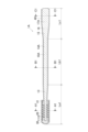
- FIG. 2 is an explanatory diagram illustrating an overall vertical cross-section of the guidewire of the first embodiment
- FIG. 2 is an explanatory diagram illustrating an A1-A1 cross section of the guidewire of the first embodiment
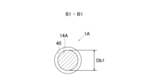
- FIG. 2 is an explanatory diagram illustrating a B1-B1 cross section of the guidewire of the first embodiment
- FIG. 2 is an explanatory diagram illustrating a C1-C1 cross section of the guidewire of the first embodiment
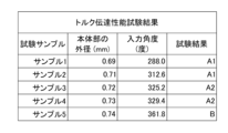
- It is the figure which showed the test result of the torque transmission performance test.
- FIG. 4 is an explanatory diagram showing a test method for a torque transmission performance test
- FIG. 4 is an explanatory diagram showing a test method for a torque transmission performance test
- FIG. 4 is a diagram showing test results of a delivery performance test
- FIG. 3 is an explanatory diagram showing a test method for a delivery performance test
- FIG. 4 is an explanatory diagram showing an example of good delivery performance
- FIG. 4 is an explanatory diagram showing an example of poor delivery performance
- FIG. 10 is a diagram showing measurement results of a bending load of a catheter
- FIG. 4 is a diagram illustrating a state in which a guidewire is indwelled in a blood vessel of a lower extremity of a human body
- FIG. 10 is an explanatory diagram illustrating an overall vertical cross-section of the guidewire of the second embodiment
- FIG. 10 is an explanatory diagram illustrating the A2-A2 cross section of the guidewire of the second embodiment
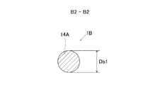
- FIG. 10 is an explanatory diagram illustrating a B2-B2 cross section of the guidewire of the second embodiment
- FIG. 10 is an explanatory diagram illustrating a C2-C2 cross section of the guidewire of the second embodiment
- FIG. 11 is an explanatory diagram illustrating an overall vertical cross-section of a guidewire according to a third embodiment
- FIG. 11 is an explanatory diagram illustrating the A3-A3 cross section of the guidewire of the third embodiment
- FIG. 11 is an explanatory diagram illustrating a B3-B3 cross section of the guidewire of the third embodiment
- FIG. 11 is an explanatory diagram illustrating a C3-C3 cross section of the guidewire of the third embodiment
- FIG. 11 is an explanatory diagram illustrating an overall vertical cross-section of a guidewire according to a fourth embodiment
- FIG. 12 is an explanatory diagram illustrating an A4-A4 cross section of the guidewire of the fourth embodiment
- FIG. 11 is an explanatory diagram illustrating a B4-B4 cross section of the guidewire of the fourth embodiment
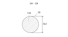
- FIG. 11 is an explanatory diagram illustrating a C4-C4 cross section of the guidewire of the fourth embodiment
- FIG. 27 is an explanatory diagram exemplifying an enlarged X region in FIG. 26;
- a guide wire is a medical device that is inserted into blood vessels and digestive organs by a doctor or the like and used for treatment and examination.
- distal side of the guidewire and guidewire components of the present invention
- distal side of the guidewire and guidewire components of the present invention
- distal side It is called the "rear end side” of the member.
- the distal end of the guidewire is the side that is inserted into the body before the guidewire is inserted into the body
- rearward end of the guidewire is the side that is operated by an operator such as a doctor (proximal). side).
- the end located on the distal side of the guide wire and each component of the guide wire is referred to as the "tip", and the part including the "tip” and extending halfway toward the rear end from the tip is the "tip". and described.
- the end located on the rear end side of the guide wire and each component member of the guide wire is referred to as the "rear end", and the portion including the “rear end” and extending halfway from the rear end toward the distal side is Described as “rear end”.
- the left-right direction in each of FIGS. 1, 2, 14, 18 and 22 is referred to as the longitudinal direction of the guide wire and each component of the guide wire. Also, the direction orthogonal to the longitudinal direction is called the radial direction of the guide wire and each component of the guide wire.
- each of FIGS. 1 to 27 includes a portion describing the relative size ratio of the guide wire and each component of the guide wire in a relative ratio different from the actual size.
- the outer diameter of the core shaft is the average value of all the measured outer diameters. Further, in the present application, that the outer diameter of the core shaft is substantially constant means that the maximum value of the outer diameter of the core shaft is 1.05 times or less the minimum value. In the present application, the outer diameter of the core shaft is measured by an outer diameter measuring device that uses a laser beam in a non-contact manner, and is measured at intervals of 0.15 mm or less in the longitudinal direction of the core shaft.
- FIG. 1 is an explanatory diagram illustrating the overall configuration of the guidewire 1A of the first embodiment.
- FIG. 1 illustrates the inside of the resin film 40 through the resin film 40 .
- FIG. 2 is an explanatory diagram illustrating the entire longitudinal section of the guidewire 1A of the first embodiment.
- the guide wire 1A of the first embodiment is a medical device that is used by percutaneously inserting it into a blood vessel to treat stenosis that has occurred in a lower limb blood vessel.
- the guide wire 1A has a core shaft 10A, a coil 20 covering part of the outer circumference of the core shaft 10A, and a resin film 40.
- a distal end portion of the coil 20 and a distal end portion of the core shaft 10A are fixed by a distal end side fixing portion 30 .
- the rear end portion of the coil 20 and the core shaft 10A are fixed by a rear end side fixing portion 31. As shown in FIG.
- the core shaft 10A is a member with an overall length of about 2000mm to about 4000mm.
- the core shaft 10A has a circular cross section and a maximum outer diameter of 0.58 mm or more and about 1.0 mm or less.
- the core shaft 10A has a small diameter portion 11, a main body portion 14A, and a large diameter portion 15 from the front end side to the rear end side.
- the small diameter portion 11 is a portion having an outer diameter smaller than the outer diameter Db1 of the main body portion 14A.
- the small diameter portion 11 has a distal straight portion 12 and a distal tapered portion 13 .
- the tip-side straight portion 12 constitutes the tip of the core shaft 10A, and its outer diameter Da1 (FIG. 3) is substantially constant along the longitudinal direction of the core shaft 10A.
- the tip-side tapered portion 13 is provided between the tip-side straight portion 12 and the body portion 14A, and has a tapered shape in which the outer diameter gradually increases toward the rear end side of the core shaft 10A.
- a part of the outer circumference of the small diameter portion 11 is covered with the coil 20 .
- a portion of the small-diameter portion 11 that is covered with the coil 20 is used as a reinforcing portion.
- the main body portion 14A is provided between the small diameter portion 11 and the large diameter portion 15 of the core shaft 10A, and its outer diameter Db1 (FIG. 4) is substantially constant along the longitudinal direction of the core shaft 10A.
- the large diameter portion 15 is a portion having an outer diameter larger than the outer diameter Db1 of the main body portion 14A.
- the large diameter portion 15 has a rear end tapered portion 16 and a rear end straight portion 17A.
- the rear end side tapered portion 16 is provided between the main body portion 14A and the rear end side straight portion 17A, and has a tapered shape in which the outer diameter gradually increases toward the rear end side of the core shaft 10A.
- the rear end side straight portion 17A constitutes the rear end of the core shaft 10A, and its outer diameter Dc1 (FIG. 5) is substantially constant along the longitudinal direction of the core shaft 10A.
- the large-diameter portion 15 functions as a high-rigidity portion having higher torsional rigidity than the main body portion 14A.
- La1 is the length of the small diameter portion 11 in the major axis direction.
- Lb1 is the length of the main body portion 14A in the longitudinal direction.
- Lc1 is the length of the large diameter portion 15 in the major axis direction.
- the body portion 14A is made of a nickel-titanium alloy.
- a nickel-titanium alloy is an alloy whose composition consists predominantly of nickel and titanium.
- a nickel-titanium alloy is an alloy having about 54% to about 57.0 wt% nickel and the remainder of which is titanium.
- Nickel-titanium alloys may also contain inclusions such as carbon, cobalt, copper, and chromium.
- Portions of the core shaft 10A other than the main body 14A can be made of materials such as nickel-titanium alloys, stainless steel alloys (SUS302, SUS304, SUS316, etc.), piano wires, nickel-chromium alloys, cobalt alloys, and tungsten.
- the body portion 14A and the portion of the core shaft 10A other than the body portion 14A are made of the same material, that is, a nickel-titanium alloy.
- the coil 20 is an example of the reinforcing body described in the claims of this application.
- the coil 20 is a tubular member that partially covers the outer circumference of the small diameter portion 11 .
- the coil 20 is formed by spirally winding a thin metal wire.
- the coil 20 can be made of materials such as nickel-titanium alloys, stainless steel alloys (SUS302, SUS304, SUS316, etc.), piano wires, nickel-chromium alloys, cobalt alloys, and tungsten.
- the distal end portion of the core shaft 10A and the distal end portion of the coil 20 are fixed by a distal end side fixing portion 30.
- a rear end portion of the core shaft 10 ⁇ /b>A and a rear end portion of the coil 20 are fixed by a rear end side fixing portion 31 .
- the distal end portion of the distal end side fixing portion 30 is formed to have a hemispherical shape.
- the front end side fixing portion 30 and the rear end side fixing portion 31 are formed by, for example, metal solder such as silver brazing or gold brazing, or an adhesive agent using epoxy resin.
- the resin film 40 is a thin film member that covers the entire length of the outer circumference of the guide wire 1A.
- the resin film 40 is made of, for example, polyvinyl alcohol, polyvinylpyrrolidone, polyethylene glycol, polyacrylamide, polyacrylic acid, sodium polyacrylate, polyurethane, polytetrafluoroethylene, perfluoroalkoxyalkane, poly(2-hydroxyethyl methacrylate), anhydrous Maleic acid copolymer, ethylene vinyl alcohol copolymer, 2-methacryloyloxyethylphosphorylcholine or its copolymer, (2-hydroxyethyl methacrylate)-styrene block copolymer, various synthetic polypeptides, collagen, hyaluronic acid, Formed by cellulosic polymers, mixtures thereof, and the like.
- FIG. 3 is an explanatory diagram illustrating the A1-A1 cross section of the guidewire 1A of the first embodiment.
- FIG. 3 shows a cross section of the distal straight portion 12 .
- FIG. 4 is an explanatory diagram illustrating the B1-B1 cross section of the guidewire 1A of the first embodiment.
- FIG. 4 shows a cross section of the body portion 14A.
- FIG. 5 is an explanatory diagram illustrating the C1-C1 cross section of the guidewire 1A of the first embodiment.
- FIG. 5 shows a cross section of the rear end side straight portion 17A.
- the cross section of the distal straight portion 12 is circular with an outer diameter Da1.
- the distal straight portion 12 is the thinnest portion of the core shaft 10A.
- the outer diameter Da1 of the distal end side straight portion 12 is smaller than the outer diameter Db1 of the main body portion 14A.
- the cross section of the body portion 14A is circular with an outer diameter Db1.
- the outer diameter Db1 of the main body portion 14A is larger than the outer diameter Da1 of the front end side straight portion 12 and smaller than the outer diameter Dc1 of the rear end side straight portion 17A.
- the rear end side straight portion 17A has a circular cross section with an outer diameter Dc1.
- the rear end side straight portion 17A is the thickest portion of the core shaft 10A.
- the outer diameter Dc1 of the rear end side straight portion 17A is larger than the outer diameter Db1 of the main body portion 14A.
- the outer diameter Db1 of the body portion 14A is set to 0.58 mm or more and 0.73 mm or less in consideration of the torque transmission performance and delivery performance of the guide wire used in the crossover method. Further, as will be described later, the outer diameter Db1 of the main body portion 14A is more preferably 0.58 mm or more and 0.71 mm or less.
- FIG. 6 is a diagram showing test results of a torque transmission performance test.
- five types (Samples 1 to 5) of guidewires having different body diameters Db1 were prepared. As shown in FIG. 6, the larger the sample number, the larger the outer diameter Db1 of the main body 14A.
- the "input angle" in FIG. 6 is the evaluation value of each sample obtained by the torque transmission performance test, and the "test result” is the result determined from the evaluation value of the "input angle".
- samples with an input angle of 315 degrees or less are labeled as “A1”
- samples with an input angle of greater than 315 degrees and less than or equal to 360 degrees are labeled with "A2”
- samples with an input angle of greater than 360 degrees are labeled with "B”.
- Fig. 7 is an explanatory diagram showing the test method of the torque transmission performance test.
- the blood vessel model T4 for torque performance test is provided with a simulated blood vessel T5 that simulates the CIA and its surrounding blood vessels.
- the torque transmission performance test is performed by the following procedure using the torque transmission performance test blood vessel model T4.
- the catheter T3 is arranged over the entire length of the simulated blood vessel T5.
- the guide wire 1S which is one of the samples 1 to 5
- the rear end of the guide wire 1S is connected to the guide wire rotation unit T1, and rotated in the direction of rotation T2 in FIG. 7 by the rotation unit T1.
- the measurement marker T6 attached to the tip of the guide wire 1S is photographed by the camera T7, and the input angle of the rotation unit T1 when the rotation angle reaches 180 degrees is recorded.
- the "input angle" column in FIG. 6 shows the input angle of the rotation unit T1 when the rotation angle of the measurement marker T6 is 180 degrees for each of the samples 1-5.
- the rotation angle of the measurement marker T6 corresponds to the rotation angle of the distal end of the guidewire 1S.
- the input angle of the rotation unit T1 corresponds to the rotation angle when the operator rotates the rear end of the guide wire 1S.
- the samples with test results A1 and A2 were judged to have good torque transmission performance.
- the sample with test results A1 was judged to be better. This criterion is based on the fact that when the operator rotates the distal end of the guidewire to determine the direction of movement at a bifurcation of a blood vessel, one finger operation of the operator (the rear end of the guidewire is rotated approximately once) It was determined in consideration of the fact that the tip of the guide wire is required to have torque transmission performance to the extent that it rotates half a turn depending on the operation).
- A1 is a sample that exhibits better torque transmission performance, such that the operator can turn the distal end of the guidewire half a turn without turning the posterior end of the guidewire once.
- A2 is a sample in which the tip of the tip can be rotated halfway. From the test results, it can be determined that samples 3 and 4 have good torque transmission performance, and samples 1 and 2 have better torque transmission performance. From this, when the outer diameter Db1 of the main body portion 14A is 0.73 mm or less, the torque transmission performance is good, and when the outer diameter Db1 of the main body portion 14A is 0.71 mm or less, the torque transmission performance is better. can be determined to be
- FIG. 8 is a diagram showing test results of a delivery performance test.
- the delivery performance test as shown in FIG. 8, five types (Samples 6 to 10) of guidewires having different body diameters Db1 were prepared. As shown in FIG. 8, the larger the sample number, the larger the outer diameter Db1 of the main body 14A.
- the test method and evaluation method of the delivery performance test will be described later with reference to FIGS. 9 to 11.
- FIG. "Test results" in FIG. 8 are the results evaluated by the evaluation method described later.
- the sample in which the situation shown in FIG. 10 occurred at the time of delivery was designated as "A”
- the sample in which the state shown in FIG. 11 occurred was designated as "B”. Samples with a test result of A show good delivery performance.
- a sample with a test result of B indicates that the delivery performance was not good.
- FIG. 9 is an explanatory diagram showing the test method of the delivery performance test.
- FIG. 10 is an explanatory diagram showing an example of good delivery performance in the delivery performance test.
- FIG. 11 is an explanatory diagram showing an example of poor delivery performance in the delivery performance test.
- FIG. 12 shows measurement results of the bending load of the catheter used in the delivery performance test.
- the delivery performance test blood vessel model T8 is provided with a simulated blood vessel T9 that imitates the shape of the CIA and the blood vessels near the CIA.
- the delivery performance test is conducted according to the following procedure. First, the guide wire 1S, which is one of the samples 6 to 10, is inserted into the simulated blood vessel T9 through the opening T11 provided at the end of the simulated blood vessel T9, and the main body portion is placed in the curved portion 100 of the CIA. left in place. Next, the catheter T10 is inserted along the guide wire 1A through the opening T11 into the simulated blood vessel T9. In this test, the catheter T10 used was Terumo Corporation's DESTINATION (registered trademark), which is a catheter commonly used in lower extremity vascular treatment.
- Catheter T10 has an inner diameter of approximately 2.24 mm and an outer diameter of approximately 2.79 mm.
- FIG. 12 shows the bending load corresponding to the distance from the tip of the catheter T10.
- the catheter T10 is then advanced over the bend 100 of the CIA toward the EIA.
- the catheter T10 can be advanced beyond the curved portion 100 of the CIA without the position of the main body of the indwelling guidewire 1A changing significantly by moving the catheter T10.
- the resulting sample was judged to have good delivery performance.
- the position of the main body of the indwelling guidewire 1S is greatly changed by attempting to advance the catheter T10 toward the EIA, and the main body and the catheter T10 move toward the AA. It was judged that the delivery performance was not good for the sample in which the catheter T10 could not be advanced beyond the curved portion 100 of the CIA by being pushed out.
- FIG. 13 is an explanatory diagram illustrating a state in which the guidewire 1A is indwelled in the lower limb blood vessel of the human body by the crossover method.
- the main body having the outer diameter Db1 obtained in the torque transmission performance test and the delivery performance test described above when the guidewire is indwelled in the blood vessel of the lower limb by the crossover method is located at the curved portion of the blood vessel of the lower limb.
- blood vessels of the lower extremities are formed in the order AA (abdominal aorta), CIA (common iliac artery), EIA (external iliac artery), and CFA (common femoral artery) from the abdomen toward the toes. It is CFA branches into SFA (superficial femoral artery) and DFA (deep femoral artery), and SFA is pop. A (popliteal artery), Pop. A is ATA (anterior tibial artery), PTA (posterior tibial artery), Pero. It branches into A (peroneal artery).
- the BK region in FIG. 13 includes ATA, PTA and Pero. Lower extremity vessels including A are shown.
- CIA, EIA, and CFA tend to have highly curved vessels such as the curved portion 100 of the CIA.
- the X region shown in FIG. 13 indicates a region containing blood vessels with a large degree of curvature.
- L1 shown in FIG. 13 is the length from the end of AA to the end of CFA. L1 is approximately 150 mm according to CT scan data obtained from the patient.
- the puncture portion 101 which is the position where the guide wire 1A is inserted in the crossover method, is often near the distal end of the CFA, the distance from the puncture portion 101 to the distal end of the AA is approximately the same as L1.
- the length from the puncture portion 101 to the end of the CFA on the other leg is approximately 300 mm.
- L2 extends from the end of CFA to Pop. It is the length up to the end of A.
- L2 is about 350 mm to about 450 mm according to CT scan data obtained from the patient. For example, ATA, PTA or Pero.
- CT scan data obtained from the patient. For example, ATA, PTA or Pero.
- the length of the core shaft 10A of the guidewire 1A is about 350 mm from the tip.
- a range of 350 mm or more and about 650 mm or less is arranged in the X region.
- the X region should be about 350 mm or more from the tip of the core shaft 10A of the guide wire 1A and about 750 mm or more. It is a part that is likely to be placed.
- the portion of the core shaft 10A that is arranged in the X region changes depending on the location of the constricted portion Le and the location of the puncture portion 101 .
- the inventors identified a position in the human body where the puncture site 101 can be easily set, and made it so that the tip of the guide wire reaches the BK region where the constriction Le is likely to occur and torque transmission and delivery are most required. The above setting was performed so that the main body portion 14A is positioned in the X region even when the guidewire is placed in the X region.
- the portion of the core shaft 10A that is 350 mm or more and 750 mm or more from the distal end is the main body portion 14A.
- the outer diameter Db1 of the body portion 14A is 0.73 mm or less.
- the outer diameter Db1 of the body portion 14A may be 0.71 mm or less.
- the amount of strain due to bending deformation is further reduced, and the contact resistance that the main body portion 14A receives from the inner wall of the blood vessel is further reduced.
- 1A can exhibit better torque transmission performance even in the crossover method.
- the outer diameter Db1 of the body portion 14A is 0.58 mm or more, the guidewire 1A can exhibit good delivery performance even in the crossover method.
- the body portion 14A is made of a nickel-titanium alloy. As a result, deterioration of operability due to deformation of the core shaft 10A can be reduced even when the main body is inserted into the CIA, EIA, and CFA, which have relatively large degrees of curvature.
- the outer diameter Db1 of the body portion 14A is substantially the same in length in the longitudinal direction.
- a tapered shape in which the outer diameter Db1 of the main body portion 14A gradually increases along the long axis direction a stepped shape in which the outer diameter Db1 of the main body portion 14A increases for each fixed length in the long axis direction, etc.
- good torque transmission performance and delivery performance can be exhibited regardless of the relative positional relationship between the body portion 14A and the blood vessel. In other words, good torque transmission performance and delivery performance are achieved in both cases where the front end side and the rear end side of the body portion 14A are arranged in the CIA, EIA, and CFA, which have relatively large degrees of curvature. can be demonstrated.
- the guide wire 1A of the first embodiment has a resin film 40.
- the sliding resistance between the outer peripheral surface of the guidewire 1A and the inside of the blood vessel can be reduced, and the slipperiness of the guidewire 1A inside the blood vessel is improved.
- the guidewire 1A of the first embodiment has a coil 20.
- the strength of the reinforcing portion of the guide wire 1A that is inserted into the narrower blood vessel at the distal end can be improved by the reinforcing body.
- the reinforcing portion is the portion of the small diameter portion 11 whose outer circumference is covered with the coil 20 .
- the guide wire 1A has the small-diameter portion 11, the flexibility of the distal end side of the guide wire 1A can be further improved.
- the guide wire 1A has a distal side tapered portion 13. As shown in FIG. As a result, the flexural rigidity of the core shaft 10A can be gradually increased from the distal end straight portion 11 toward the main body portion 14A.
- the guidewire 1A also has a large diameter portion 15 .
- the torsional rigidity of the rear end portion of the guide wire 1A is high, so the torque transmission performance can be further improved.
- the guide wire 1A has a rear end tapered portion 16. As shown in FIG. As a result, the flexural rigidity of the core shaft 10A can be gradually increased from the body portion 14A toward the rear end side straight portion 17A, and stress is concentrated on the portion between the body portion 14A and the rear end side straight portion 17A. Therefore, it is possible to reduce the possibility that the core shaft 10A will kink.
- FIG. 14 is an explanatory view exemplifying the longitudinal section of the entire guidewire 1B of the second embodiment.
- FIG. 15 is an explanatory diagram illustrating the A2-A2 cross section of the guide wire 1B of the second embodiment.
- FIG. 16 is an explanatory diagram illustrating the B2-B2 cross section of the guide wire 1B of the second embodiment.
- FIG. 17 is an explanatory diagram illustrating the C2-C2 cross section of the guide wire 1B of the second embodiment.
- the guidewire 1B of the second embodiment differs from the guidewire 1A of the first embodiment in that it does not have a large diameter portion 15 (Fig. 2). Portions other than the large diameter portion 15 of the guide wire 1B of the second embodiment are common to the guide wire 1A of the first embodiment.
- the guide wire 1B has a core shaft 10B with a rear end side straight portion 17B.
- the rear end side straight portion 17B is a portion that is on the rear end side of the main body portion 14A and constitutes the rear end portion of the core shaft 10B.
- Lc2 is the length in the longitudinal direction of the rear end side straight portion 17B.
- the outer diameter Dc2 of the rear end side straight portion 17B is substantially the same as the outer diameter Db1 of the main body portion 14A.
- the guide wire 1B of the second embodiment described above can also exhibit the same effects as the guide wire 1A of the first embodiment. Since the outer diameter Dc2 of the rear end side straight portion 17B is substantially the same as the outer diameter Db1 of the main body portion 14A, for example, CIA, EIA, and CFA, which have a large degree of curvature, are longer than expected, and are located on the rear end side of the main body portion 14A. Even when the core shaft 10B is placed in those blood vessels, good torque transmission performance and delivery performance can be exhibited.
- FIG. 18 is an explanatory view exemplifying the longitudinal section of the entire guidewire 1C of the third embodiment.
- FIG. 19 is an explanatory diagram illustrating the A3-A3 cross section of the guidewire 1C of the third embodiment.
- FIG. 20 is an explanatory diagram illustrating the B3-B3 cross section of the guidewire 1C of the third embodiment.
- FIG. 21 is an explanatory view exemplifying the C3-C3 cross section of the guide wire 1C of the third embodiment.
- the rear end side straight portion 17C of the guidewire 1C is formed of a different material having higher torsional rigidity than the main portion 14A. Different in Parts other than the rear end side straight portion 17C of the guide wire 1C of the third embodiment are common to the guide wire 1A of the first embodiment.
- the rear end side straight portion 17C is a portion depicted in FIG. 18 with a hatching pattern different from that of the main body portion 14A.
- the guide wire 1C has a core shaft 10C having a rear end side straight portion 17C.
- the rear end side straight portion 17C is a portion that is on the rear end side of the main body portion 14A and constitutes the rear end portion of the core shaft 10C.
- the outer diameter Dc3 of the rear end side straight portion 17C is substantially the same as the outer diameter Db1 of the main body portion 14A.
- Lc3 is the length in the longitudinal direction of the rear end side straight portion 17C.
- the rear end side straight portion 17C is made of a different material having a higher lateral elastic modulus than the material of the main body portion 14A.
- the rear straight portion 17C can be made of materials such as stainless alloy (SUS302, SUS304, SUS316, etc.), piano wire, nickel-chromium alloy, cobalt alloy, and tungsten.
- the rear end portion of the main body portion 14A and the front end portion of the rear end side straight portion 17C are joined by a method such as soldering, adhesive, or welding.
- the guidewire 1C of the third embodiment described above can also exhibit the same effects as the guidewire 1A of the first embodiment.
- the lateral elastic modulus of the material of the rear end side straight portion 17C is higher than that of the material of the main body portion 14A, the torsional rigidity of the rear end portion of the core shaft 10C is higher, resulting in better torque transmission performance. can demonstrate.
- FIG. 22 is an explanatory view exemplifying the longitudinal section of the entire guide wire 1D of the fourth embodiment.
- FIG. 23 is an explanatory diagram illustrating the A4-A4 section of the guide wire 1D of the fourth embodiment.
- FIG. 24 is an explanatory diagram illustrating the B4-B4 cross section of the guide wire 1D of the fourth embodiment.
- FIG. 25 is an explanatory diagram illustrating the C4-C4 cross section of the guide wire 1D of the fourth embodiment.
- the body portion 14D of the guidewire 1D has a tapered shape in which the outer diameter Db4 gradually increases toward the rear end side of the core shaft 10D. different in that. Parts other than the main body portion 14D of the guide wire 1D of the fourth embodiment are common to the guide wire 1A of the first embodiment.
- the guidewire 1D has a core shaft 10D with a body portion 14D.
- the outer diameter Db4 of the body portion 14D gradually increases toward the rear end side of the core shaft 10D.
- Lb4 is the length of the main body portion 14D in the longitudinal direction.
- the guide wire 1D of the fourth embodiment described above can also exhibit the same effects as the guide wire 1A of the first embodiment. Since the main body portion 14D of the guide wire 1D has a tapered shape, the flexural rigidity of the core shaft 10D can be gradually increased from the small diameter portion 11 toward the large diameter portion 15. As shown in FIG. Therefore, it is possible to reduce the possibility that stress concentrates on the body portion 14D and the body portion 14D kinks.
- the distal side straight portion 12, the main body portion 14A, and the rear end side straight portion 17A are straight, and the distal side tapered portion 13 and the rear end side tapered portion 16 are formed on the distal side.
- the outer diameter of each portion of the core shaft may be a straight shape in which the outer diameter is substantially constant in the long axis direction, or a tapered shape in which the outer diameter gradually increases or decreases toward the rear end side of the core shaft. It's okay.
- the outer diameter of each portion of the core shaft may have a stepped shape in which the outer diameter increases or decreases for each fixed length in the longitudinal direction of the core shaft.
- the cross section of the core shaft 10 of the guide wire 1A of the first embodiment is circular.
- the cross section of the core shaft 10 does not have to be circular, and may be rectangular such as square or rectangular, or triangular.
- the cross section of the distal straight portion 12 of the guide wire 1A is anisotropic in the direction in which deformation is likely to occur, such as a rectangle, the operator can easily shape the distal end portion of the guide wire. .
- the torsional rigidity is higher on the rear end side than on the front end side.
- the core shaft may be configured to have greater torsional stiffness on the distal end side in its longitudinal direction.
- the torsional rigidity of the small diameter portion may be higher than the torsional rigidity of the body portion.
- the resin film 40 of the first embodiment is composed of a single type, and its characteristics do not change.
- the properties of the resin film covering the outer circumference of the core shaft may change in the longitudinal direction of the core shaft.
- the main body and the large diameter portion may be covered with a hydrophobic resin film, or only the large diameter portion may be covered with a hydrophobic resin film.
- a guide wire whose large diameter portion is covered with a hydrophobic resin film can have sufficient frictional force to allow an operator to easily grip the guide wire while having the sliding performance of the guide wire.
- the entire body portion may be covered with resin films having the same properties, or different portions of the body portion may be covered with a plurality of resin films having different properties.
- part or all of the core shaft may be covered with a plurality of layers of resin.
- the outer circumferences of the coil and the main body may be covered with a resin film containing urethane, and the outer circumference of the resin film containing urethane may be covered with a hydrophilic resin film.
- the reinforcing body of the first embodiment is formed by spirally winding a thin metal wire.
- the reinforcing body may be a hollow coil formed by twisting a plurality of metal filaments.
- the guidewire may not have a reinforcing body.
- the outer circumference of the tip portion of the core shaft may be covered with a resin film.
Landscapes
- Health & Medical Sciences (AREA)
- Life Sciences & Earth Sciences (AREA)
- Surgery (AREA)
- General Health & Medical Sciences (AREA)
- Engineering & Computer Science (AREA)
- Veterinary Medicine (AREA)
- Biomedical Technology (AREA)
- Heart & Thoracic Surgery (AREA)
- Public Health (AREA)
- Animal Behavior & Ethology (AREA)
- Medical Informatics (AREA)
- Nuclear Medicine, Radiotherapy & Molecular Imaging (AREA)
- Molecular Biology (AREA)
- Orthopedic Medicine & Surgery (AREA)
- Vascular Medicine (AREA)
- Hematology (AREA)
- Anesthesiology (AREA)
- Pulmonology (AREA)
- Biophysics (AREA)
- Media Introduction/Drainage Providing Device (AREA)
Priority Applications (5)
| Application Number | Priority Date | Filing Date | Title |
|---|---|---|---|
| PCT/JP2021/035773 WO2023053245A1 (ja) | 2021-09-29 | 2021-09-29 | ガイドワイヤ |
| CN202180102768.8A CN118076406A (zh) | 2021-09-29 | 2021-09-29 | 导丝 |
| JP2023550825A JP7682286B2 (ja) | 2021-09-29 | 2021-09-29 | ガイドワイヤ |
| EP21959293.8A EP4410353A4 (en) | 2021-09-29 | 2021-09-29 | GUIDE WIRE |
| US18/619,678 US20240237996A1 (en) | 2021-09-29 | 2024-03-28 | Guide wire |
Applications Claiming Priority (1)
| Application Number | Priority Date | Filing Date | Title |
|---|---|---|---|
| PCT/JP2021/035773 WO2023053245A1 (ja) | 2021-09-29 | 2021-09-29 | ガイドワイヤ |
Related Child Applications (1)
| Application Number | Title | Priority Date | Filing Date |
|---|---|---|---|
| US18/619,678 Continuation US20240237996A1 (en) | 2021-09-29 | 2024-03-28 | Guide wire |
Publications (1)
| Publication Number | Publication Date |
|---|---|
| WO2023053245A1 true WO2023053245A1 (ja) | 2023-04-06 |
Family
ID=85781540
Family Applications (1)
| Application Number | Title | Priority Date | Filing Date |
|---|---|---|---|
| PCT/JP2021/035773 Ceased WO2023053245A1 (ja) | 2021-09-29 | 2021-09-29 | ガイドワイヤ |
Country Status (5)
| Country | Link |
|---|---|
| US (1) | US20240237996A1 (https=) |
| EP (1) | EP4410353A4 (https=) |
| JP (1) | JP7682286B2 (https=) |
| CN (1) | CN118076406A (https=) |
| WO (1) | WO2023053245A1 (https=) |
Families Citing this family (4)
| Publication number | Priority date | Publication date | Assignee | Title |
|---|---|---|---|---|
| US10285720B2 (en) | 2014-03-11 | 2019-05-14 | Neuravi Limited | Clot retrieval system for removing occlusive clot from a blood vessel |
| ES2989493T3 (es) | 2014-06-13 | 2024-11-26 | Neuravi Ltd | Dispositivos para eliminar las obstrucciones agudas de los vasos sanguíneos |
| US12539130B2 (en) | 2019-11-27 | 2026-02-03 | Neuravi Limited | Aspiration catheter, systems, and methods thereof |
| US20260097189A1 (en) * | 2024-10-09 | 2026-04-09 | Neuravi Limited | Navigation device for use with a funnel catheter minimizing catching at a vessel bifurcation |
Citations (6)
| Publication number | Priority date | Publication date | Assignee | Title |
|---|---|---|---|---|
| JP2000503225A (ja) * | 1996-01-16 | 2000-03-21 | ボストン・サイエンティフィック・コーポレーション | 医用ガイドワイヤ |
| JP2005508229A (ja) * | 2001-11-05 | 2005-03-31 | メンリー コーポレイション | 加工硬化擬弾性ガイドワイヤ |
| JP2005211511A (ja) * | 2004-01-30 | 2005-08-11 | Terumo Corp | ガイドワイヤ |
| JP2007537009A (ja) * | 2004-05-14 | 2007-12-20 | エシコン・エンド−サージェリィ・インコーポレイテッド | ガイドワイヤ構造体 |
| JP2016174645A (ja) | 2015-03-18 | 2016-10-06 | テルモ株式会社 | ガイドワイヤ |
| JP2017153615A (ja) * | 2016-02-29 | 2017-09-07 | 株式会社パイオラックスメディカルデバイス | ガイドワイヤ及びその製造方法 |
Family Cites Families (5)
| Publication number | Priority date | Publication date | Assignee | Title |
|---|---|---|---|---|
| US8167821B2 (en) * | 2003-02-26 | 2012-05-01 | Boston Scientific Scimed, Inc. | Multiple diameter guidewire |
| JP4987531B2 (ja) * | 2007-03-27 | 2012-07-25 | 日本ライフライン株式会社 | 医療用ガイドワイヤおよびその製造方法 |
| US20130110000A1 (en) * | 2011-10-31 | 2013-05-02 | Terumo Medical Corporation | Dual Diameter Introducer Guide Wire |
| US10029076B2 (en) * | 2012-02-28 | 2018-07-24 | Covidien Lp | Intravascular guidewire |
| US20150148706A1 (en) * | 2013-11-26 | 2015-05-28 | Boston Scientific Scimed, Inc. | Medical devices for accessing body lumens |
-
2021
- 2021-09-29 WO PCT/JP2021/035773 patent/WO2023053245A1/ja not_active Ceased
- 2021-09-29 JP JP2023550825A patent/JP7682286B2/ja active Active
- 2021-09-29 CN CN202180102768.8A patent/CN118076406A/zh active Pending
- 2021-09-29 EP EP21959293.8A patent/EP4410353A4/en active Pending
-
2024
- 2024-03-28 US US18/619,678 patent/US20240237996A1/en active Pending
Patent Citations (6)
| Publication number | Priority date | Publication date | Assignee | Title |
|---|---|---|---|---|
| JP2000503225A (ja) * | 1996-01-16 | 2000-03-21 | ボストン・サイエンティフィック・コーポレーション | 医用ガイドワイヤ |
| JP2005508229A (ja) * | 2001-11-05 | 2005-03-31 | メンリー コーポレイション | 加工硬化擬弾性ガイドワイヤ |
| JP2005211511A (ja) * | 2004-01-30 | 2005-08-11 | Terumo Corp | ガイドワイヤ |
| JP2007537009A (ja) * | 2004-05-14 | 2007-12-20 | エシコン・エンド−サージェリィ・インコーポレイテッド | ガイドワイヤ構造体 |
| JP2016174645A (ja) | 2015-03-18 | 2016-10-06 | テルモ株式会社 | ガイドワイヤ |
| JP2017153615A (ja) * | 2016-02-29 | 2017-09-07 | 株式会社パイオラックスメディカルデバイス | ガイドワイヤ及びその製造方法 |
Non-Patent Citations (1)
| Title |
|---|
| See also references of EP4410353A4 |
Also Published As
| Publication number | Publication date |
|---|---|
| EP4410353A1 (en) | 2024-08-07 |
| US20240237996A1 (en) | 2024-07-18 |
| CN118076406A (zh) | 2024-05-24 |
| JPWO2023053245A1 (https=) | 2023-04-06 |
| JP7682286B2 (ja) | 2025-05-23 |
| EP4410353A4 (en) | 2025-07-02 |
Similar Documents
| Publication | Publication Date | Title |
|---|---|---|
| JP7682286B2 (ja) | ガイドワイヤ | |
| EP0749334B2 (en) | Catheter guidewire with radiopaque markers | |
| JP2019532767A (ja) | 複数の伸縮式カテーテルの導入および操作のための装置 | |
| KR20120027116A (ko) | 의료용 가이드 와이어 | |
| JP2016514977A (ja) | 形状記憶先端部を備えたセンサ・ガイド・ワイヤ | |
| JPWO2013140669A1 (ja) | バルーンカテーテル | |
| JP2012152362A (ja) | ガイドワイヤ | |
| JPWO2018092387A1 (ja) | カテーテル組立体 | |
| JP2016506286A (ja) | 冠状動脈ガイドワイヤ | |
| US20110319922A1 (en) | Balloon catheter | |
| WO2022158418A1 (ja) | カテーテル | |
| JP2007130116A (ja) | カテーテル | |
| JP2013111339A (ja) | カテーテルキット、ガイドワイヤ及びカテーテル | |
| JP4260058B2 (ja) | 医療用チューブの挿入具 | |
| CN116328152A (zh) | 一种球囊导管 | |
| JP2018108119A (ja) | ガイドワイヤおよび医療用コイル | |
| JP2018064890A (ja) | カテーテル組立体 | |
| JP6220056B2 (ja) | ガイドワイヤ | |
| CN216022317U (zh) | 一种造影导丝 | |
| WO2025244010A1 (ja) | カテーテル | |
| WO2022158417A1 (ja) | カテーテル | |
| JP2002143314A (ja) | 拡張カテーテル | |
| WO2022154118A1 (ja) | カテーテルおよびカテーテル組立体 | |
| CN121038841A (zh) | 扭曲导丝 | |
| JP2025035462A (ja) | カテーテル |
Legal Events
| Date | Code | Title | Description |
|---|---|---|---|
| 121 | Ep: the epo has been informed by wipo that ep was designated in this application |
Ref document number: 21959293 Country of ref document: EP Kind code of ref document: A1 |
|
| WWE | Wipo information: entry into national phase |
Ref document number: 2023550825 Country of ref document: JP |
|
| WWE | Wipo information: entry into national phase |
Ref document number: 202180102768.8 Country of ref document: CN |
|
| NENP | Non-entry into the national phase |
Ref country code: DE |
|
| ENP | Entry into the national phase |
Ref document number: 2021959293 Country of ref document: EP Effective date: 20240429 |