WO2023053245A1 - Guide wire - Google Patents
Guide wire Download PDFInfo
- Publication number
- WO2023053245A1 WO2023053245A1 PCT/JP2021/035773 JP2021035773W WO2023053245A1 WO 2023053245 A1 WO2023053245 A1 WO 2023053245A1 JP 2021035773 W JP2021035773 W JP 2021035773W WO 2023053245 A1 WO2023053245 A1 WO 2023053245A1
- Authority
- WO
- WIPO (PCT)
- Prior art keywords
- guide wire
- guidewire
- core shaft
- main body
- rear end
- Prior art date
Links
- 229910001000 nickel titanium Inorganic materials 0.000 claims abstract description 13
- 210000004204 blood vessel Anatomy 0.000 description 47
- 238000010586 diagram Methods 0.000 description 47
- 230000005540 biological transmission Effects 0.000 description 33
- 238000011056 performance test Methods 0.000 description 28
- 238000000034 method Methods 0.000 description 21
- 229920005989 resin Polymers 0.000 description 19
- 239000011347 resin Substances 0.000 description 19
- 239000010408 film Substances 0.000 description 18
- 238000012360 testing method Methods 0.000 description 16
- 210000003141 lower extremity Anatomy 0.000 description 15
- 210000002465 tibial artery Anatomy 0.000 description 15
- 210000000702 aorta abdominal Anatomy 0.000 description 10
- 210000002414 leg Anatomy 0.000 description 9
- 239000000463 material Substances 0.000 description 9
- 230000003014 reinforcing effect Effects 0.000 description 9
- 210000001105 femoral artery Anatomy 0.000 description 8
- 208000031481 Pathologic Constriction Diseases 0.000 description 7
- 230000036262 stenosis Effects 0.000 description 7
- 208000037804 stenosis Diseases 0.000 description 7
- 229910045601 alloy Inorganic materials 0.000 description 6
- 239000000956 alloy Substances 0.000 description 6
- 238000005452 bending Methods 0.000 description 6
- 210000003090 iliac artery Anatomy 0.000 description 6
- 238000005259 measurement Methods 0.000 description 6
- 238000010998 test method Methods 0.000 description 6
- 238000011156 evaluation Methods 0.000 description 5
- 238000012986 modification Methods 0.000 description 5
- 230000004048 modification Effects 0.000 description 5
- PXHVJJICTQNCMI-UHFFFAOYSA-N Nickel Chemical compound [Ni] PXHVJJICTQNCMI-UHFFFAOYSA-N 0.000 description 4
- 240000001987 Pyrus communis Species 0.000 description 4
- 239000000788 chromium alloy Substances 0.000 description 4
- 239000003550 marker Substances 0.000 description 4
- 229910052751 metal Inorganic materials 0.000 description 4
- 239000002184 metal Substances 0.000 description 4
- 229910000531 Co alloy Inorganic materials 0.000 description 3
- HZEWFHLRYVTOIW-UHFFFAOYSA-N [Ti].[Ni] Chemical compound [Ti].[Ni] HZEWFHLRYVTOIW-UHFFFAOYSA-N 0.000 description 3
- 230000000694 effects Effects 0.000 description 3
- 230000002209 hydrophobic effect Effects 0.000 description 3
- 229910000623 nickel–chromium alloy Inorganic materials 0.000 description 3
- -1 polytetrafluoroethylene Polymers 0.000 description 3
- 210000003137 popliteal artery Anatomy 0.000 description 3
- WFKWXMTUELFFGS-UHFFFAOYSA-N tungsten Chemical compound [W] WFKWXMTUELFFGS-UHFFFAOYSA-N 0.000 description 3
- 229910052721 tungsten Inorganic materials 0.000 description 3
- 239000010937 tungsten Substances 0.000 description 3
- JOYRKODLDBILNP-UHFFFAOYSA-N Ethyl urethane Chemical compound CCOC(N)=O JOYRKODLDBILNP-UHFFFAOYSA-N 0.000 description 2
- RTAQQCXQSZGOHL-UHFFFAOYSA-N Titanium Chemical compound [Ti] RTAQQCXQSZGOHL-UHFFFAOYSA-N 0.000 description 2
- 239000000853 adhesive Substances 0.000 description 2
- 210000001367 artery Anatomy 0.000 description 2
- 238000005219 brazing Methods 0.000 description 2
- 238000002591 computed tomography Methods 0.000 description 2
- 229920001577 copolymer Polymers 0.000 description 2
- 230000007423 decrease Effects 0.000 description 2
- 238000004519 manufacturing process Methods 0.000 description 2
- 239000000203 mixture Substances 0.000 description 2
- 229910052759 nickel Inorganic materials 0.000 description 2
- 229910001256 stainless steel alloy Inorganic materials 0.000 description 2
- 239000010936 titanium Substances 0.000 description 2
- 229910052719 titanium Inorganic materials 0.000 description 2
- 210000000689 upper leg Anatomy 0.000 description 2
- 238000004804 winding Methods 0.000 description 2
- KIUKXJAPPMFGSW-DNGZLQJQSA-N (2S,3S,4S,5R,6R)-6-[(2S,3R,4R,5S,6R)-3-Acetamido-2-[(2S,3S,4R,5R,6R)-6-[(2R,3R,4R,5S,6R)-3-acetamido-2,5-dihydroxy-6-(hydroxymethyl)oxan-4-yl]oxy-2-carboxy-4,5-dihydroxyoxan-3-yl]oxy-5-hydroxy-6-(hydroxymethyl)oxan-4-yl]oxy-3,4,5-trihydroxyoxane-2-carboxylic acid Chemical compound CC(=O)N[C@H]1[C@H](O)O[C@H](CO)[C@@H](O)[C@@H]1O[C@H]1[C@H](O)[C@@H](O)[C@H](O[C@H]2[C@@H]([C@@H](O[C@H]3[C@@H]([C@@H](O)[C@H](O)[C@H](O3)C(O)=O)O)[C@H](O)[C@@H](CO)O2)NC(C)=O)[C@@H](C(O)=O)O1 KIUKXJAPPMFGSW-DNGZLQJQSA-N 0.000 description 1
- ZSZRUEAFVQITHH-UHFFFAOYSA-N 2-(2-methylprop-2-enoyloxy)ethyl 2-(trimethylazaniumyl)ethyl phosphate Chemical compound CC(=C)C(=O)OCCOP([O-])(=O)OCC[N+](C)(C)C ZSZRUEAFVQITHH-UHFFFAOYSA-N 0.000 description 1
- OPVBUKANCGEZEQ-UHFFFAOYSA-N 5-hydroxy-2-methylpent-2-enoic acid;styrene Chemical compound C=CC1=CC=CC=C1.OC(=O)C(C)=CCCO OPVBUKANCGEZEQ-UHFFFAOYSA-N 0.000 description 1
- OKTJSMMVPCPJKN-UHFFFAOYSA-N Carbon Chemical compound [C] OKTJSMMVPCPJKN-UHFFFAOYSA-N 0.000 description 1
- VYZAMTAEIAYCRO-UHFFFAOYSA-N Chromium Chemical compound [Cr] VYZAMTAEIAYCRO-UHFFFAOYSA-N 0.000 description 1
- 102000008186 Collagen Human genes 0.000 description 1
- 108010035532 Collagen Proteins 0.000 description 1
- RYGMFSIKBFXOCR-UHFFFAOYSA-N Copper Chemical compound [Cu] RYGMFSIKBFXOCR-UHFFFAOYSA-N 0.000 description 1
- 229920000219 Ethylene vinyl alcohol Polymers 0.000 description 1
- 239000004813 Perfluoroalkoxy alkane Substances 0.000 description 1
- 239000002202 Polyethylene glycol Substances 0.000 description 1
- 239000004372 Polyvinyl alcohol Substances 0.000 description 1
- OFOBLEOULBTSOW-UHFFFAOYSA-N Propanedioic acid Natural products OC(=O)CC(O)=O OFOBLEOULBTSOW-UHFFFAOYSA-N 0.000 description 1
- BQCADISMDOOEFD-UHFFFAOYSA-N Silver Chemical compound [Ag] BQCADISMDOOEFD-UHFFFAOYSA-N 0.000 description 1
- 229920002125 Sokalan® Polymers 0.000 description 1
- 206010057469 Vascular stenosis Diseases 0.000 description 1
- 210000001015 abdomen Anatomy 0.000 description 1
- 230000001070 adhesive effect Effects 0.000 description 1
- 229910052799 carbon Inorganic materials 0.000 description 1
- 229910052804 chromium Inorganic materials 0.000 description 1
- 239000011651 chromium Substances 0.000 description 1
- 239000010941 cobalt Substances 0.000 description 1
- 229910017052 cobalt Inorganic materials 0.000 description 1
- GUTLYIVDDKVIGB-UHFFFAOYSA-N cobalt atom Chemical compound [Co] GUTLYIVDDKVIGB-UHFFFAOYSA-N 0.000 description 1
- 229920001436 collagen Polymers 0.000 description 1
- 239000012141 concentrate Substances 0.000 description 1
- 229910052802 copper Inorganic materials 0.000 description 1
- 239000010949 copper Substances 0.000 description 1
- 230000006866 deterioration Effects 0.000 description 1
- 239000003822 epoxy resin Substances 0.000 description 1
- 230000005713 exacerbation Effects 0.000 description 1
- PCHJSUWPFVWCPO-UHFFFAOYSA-N gold Chemical compound [Au] PCHJSUWPFVWCPO-UHFFFAOYSA-N 0.000 description 1
- 229910052737 gold Inorganic materials 0.000 description 1
- 239000010931 gold Substances 0.000 description 1
- 230000012447 hatching Effects 0.000 description 1
- 229920002674 hyaluronan Polymers 0.000 description 1
- 229960003160 hyaluronic acid Drugs 0.000 description 1
- 210000003127 knee Anatomy 0.000 description 1
- 239000011976 maleic acid Substances 0.000 description 1
- 210000004798 organs belonging to the digestive system Anatomy 0.000 description 1
- 229920011301 perfluoro alkoxyl alkane Polymers 0.000 description 1
- 230000002093 peripheral effect Effects 0.000 description 1
- 229920001495 poly(sodium acrylate) polymer Polymers 0.000 description 1
- 229920002401 polyacrylamide Polymers 0.000 description 1
- 239000004584 polyacrylic acid Substances 0.000 description 1
- 229920000647 polyepoxide Polymers 0.000 description 1
- 229920001223 polyethylene glycol Polymers 0.000 description 1
- 229920002338 polyhydroxyethylmethacrylate Polymers 0.000 description 1
- 229920000642 polymer Polymers 0.000 description 1
- 229920001184 polypeptide Polymers 0.000 description 1
- 229920001343 polytetrafluoroethylene Polymers 0.000 description 1
- 239000004810 polytetrafluoroethylene Substances 0.000 description 1
- 229920002635 polyurethane Polymers 0.000 description 1
- 239000004814 polyurethane Substances 0.000 description 1
- 229920002451 polyvinyl alcohol Polymers 0.000 description 1
- 229920000036 polyvinylpyrrolidone Polymers 0.000 description 1
- 239000001267 polyvinylpyrrolidone Substances 0.000 description 1
- 235000013855 polyvinylpyrrolidone Nutrition 0.000 description 1
- 102000004196 processed proteins & peptides Human genes 0.000 description 1
- 108090000765 processed proteins & peptides Proteins 0.000 description 1
- 229910052709 silver Inorganic materials 0.000 description 1
- 239000004332 silver Substances 0.000 description 1
- NNMHYFLPFNGQFZ-UHFFFAOYSA-M sodium polyacrylate Chemical compound [Na+].[O-]C(=O)C=C NNMHYFLPFNGQFZ-UHFFFAOYSA-M 0.000 description 1
- 229910000679 solder Inorganic materials 0.000 description 1
- 238000005476 soldering Methods 0.000 description 1
- 229920006132 styrene block copolymer Polymers 0.000 description 1
- 239000010409 thin film Substances 0.000 description 1
- 210000003371 toe Anatomy 0.000 description 1
- VZCYOOQTPOCHFL-UHFFFAOYSA-N trans-butenedioic acid Natural products OC(=O)C=CC(O)=O VZCYOOQTPOCHFL-UHFFFAOYSA-N 0.000 description 1
- 230000002792 vascular Effects 0.000 description 1
- 238000003466 welding Methods 0.000 description 1
Images


Classifications
-
- A—HUMAN NECESSITIES
- A61—MEDICAL OR VETERINARY SCIENCE; HYGIENE
- A61M—DEVICES FOR INTRODUCING MEDIA INTO, OR ONTO, THE BODY; DEVICES FOR TRANSDUCING BODY MEDIA OR FOR TAKING MEDIA FROM THE BODY; DEVICES FOR PRODUCING OR ENDING SLEEP OR STUPOR
- A61M25/00—Catheters; Hollow probes
- A61M25/01—Introducing, guiding, advancing, emplacing or holding catheters
- A61M25/09—Guide wires
Definitions
- the present invention relates to guidewires.
- a guide wire is conventionally known as a medical device that is used by percutaneously inserting it into a blood vessel in order to treat a stenosis that has occurred in the blood vessel.
- Patent Literature 1 describes a guide wire used for treatment of lower extremity blood vessels.
- FIG. 26 is an explanatory diagram illustrating blood vessels of the lower extremities of the human body.
- FIG. 27 is an explanatory diagram exemplifying the X area in FIG. 26 in an enlarged manner.
- the guide wire 1 is inserted into the blood vessel from the puncture site 101 near the thigh of the leg other than the leg having the stenosis Le, and passes through the common iliac artery (hereinafter referred to as the CIA).
- the leg is moved to the leg on which the constricted portion Le exists, and the leg is reached to the constricted portion Le.
- FIG. 26 illustrates a state in which the guide wire 1 is inserted into the blood vessels of the lower extremities of the human body.
- a stenosed portion Le occurs in the anterior tibial artery (hereinafter referred to as ATA) included in the below-the-knee area (hereinafter referred to as BK area).
- the guide wire 1 is first percutaneously inserted into a blood vessel in the body from a puncture site 101 near the thigh of the leg other than the leg where the constriction Le occurs.
- the guide wire 1 advances through the CIA toward the abdominal aorta (hereinafter referred to as AA), passes through the curved portion 100 of the CIA, and further advances through the CIA toward the constricted portion Le.
- AA abdominal aorta
- the guidewire 1 is used for the external iliac artery (hereinafter referred to as EIA), common femoral artery (hereinafter referred to as CFA), superficial femoral artery (hereinafter referred to as SFA) and popliteal artery (hereinafter referred to as Pop.A ) to reach the anterior tibial artery (ATA).
- EIA external iliac artery
- CFA common femoral artery
- SFA superficial femoral artery
- Pop.A popliteal artery
- the guidewire 1 is left in the vicinity of the stenosis Le, and a combined instrument such as a catheter is inserted into the blood vessel along the guidewire 1 to treat the stenosis Le.
- a combined instrument such as a catheter is inserted into the blood vessel along the guidewire 1 to treat the stenosis Le.
- the guidewire passes through the CIA, EIA, and CFA, which are relatively curved even in the blood vessels of the lower
- transmission performance transmission performance
- delivery performance improvement in the performance for allowing a combined instrument such as a catheter inserted into a blood vessel along a guide wire to pass through the CIA, which has a particularly large degree of curvature.
- the present invention has been made in order to solve the above-described problems.
- An object is to provide a guide wire that is excellent in both.
- the present invention has been made to solve at least part of the above problems, and can be implemented as the following forms.
- a guidewire is provided.
- This guide wire has a core shaft, the main body of which is 350 mm or more and 750 mm or less from the tip is made of a nickel-titanium alloy, and the main body has an outer diameter of 0.58 mm or more and 0.73 mm or less. be.
- the main body which is a portion of 350 mm or more and 750 mm or less from the tip of the core shaft, is made of a nickel-titanium alloy and has an outer diameter of 0.58 mm or more and 0.73 mm or less. It is possible to provide a guide wire that is excellent in both torque transmission performance during treatment by the crossover method and delivery performance. Specifically, since the main body is made of a nickel-titanium alloy, even when the main body passes through CIA, EIA, and CFA, which have a large degree of curvature, the operability due to the deformation of the core shaft is improved by the crossover method. Exacerbation can be reduced.
- the main body has an outer diameter of 0.58 mm or more, by placing the main body in the vicinity of the CIA, a combined instrument such as a catheter can be easily advanced from one leg to the other along the guide wire. be able to.
- the main body is 0.73 mm or less, the rotating operation of the operator can be efficiently transmitted to the distal end of the guide wire by arranging the main body near the CIA.
- the main body is in the range of 350 mm or more and 750 mm or less from the tip of the core shaft, the main body can be placed near the CIA regardless of the length of the patient's blood vessel, and torque transmission of the guide wire Performance and delivery performance can be improved in more patients.
- the outer diameter of the main body of the core shaft may be 0.71 mm or less.
- the torque transmission performance during treatment by the crossover method can be further improved. can be planned.
- the present invention can be implemented in various aspects, for example, in the form of a guidewire, a guidewire manufacturing method, a catheter manufacturing method, an endoscope, a dilator, and the like.
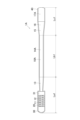
- FIG. 1 is an explanatory diagram illustrating the overall configuration of a guidewire according to a first embodiment
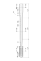
- FIG. 2 is an explanatory diagram illustrating an overall vertical cross-section of the guidewire of the first embodiment
- FIG. 2 is an explanatory diagram illustrating an A1-A1 cross section of the guidewire of the first embodiment
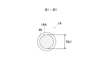
- FIG. 2 is an explanatory diagram illustrating a B1-B1 cross section of the guidewire of the first embodiment
- FIG. 2 is an explanatory diagram illustrating a C1-C1 cross section of the guidewire of the first embodiment
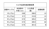
- It is the figure which showed the test result of the torque transmission performance test.
- FIG. 4 is an explanatory diagram showing a test method for a torque transmission performance test
- FIG. 4 is an explanatory diagram showing a test method for a torque transmission performance test
- FIG. 4 is a diagram showing test results of a delivery performance test
- FIG. 3 is an explanatory diagram showing a test method for a delivery performance test
- FIG. 4 is an explanatory diagram showing an example of good delivery performance
- FIG. 4 is an explanatory diagram showing an example of poor delivery performance
- FIG. 10 is a diagram showing measurement results of a bending load of a catheter
- FIG. 4 is a diagram illustrating a state in which a guidewire is indwelled in a blood vessel of a lower extremity of a human body
- FIG. 10 is an explanatory diagram illustrating an overall vertical cross-section of the guidewire of the second embodiment
- FIG. 10 is an explanatory diagram illustrating the A2-A2 cross section of the guidewire of the second embodiment
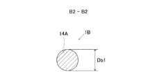
- FIG. 10 is an explanatory diagram illustrating a B2-B2 cross section of the guidewire of the second embodiment
- FIG. 10 is an explanatory diagram illustrating a C2-C2 cross section of the guidewire of the second embodiment
- FIG. 11 is an explanatory diagram illustrating an overall vertical cross-section of a guidewire according to a third embodiment
- FIG. 11 is an explanatory diagram illustrating the A3-A3 cross section of the guidewire of the third embodiment
- FIG. 11 is an explanatory diagram illustrating a B3-B3 cross section of the guidewire of the third embodiment
- FIG. 11 is an explanatory diagram illustrating a C3-C3 cross section of the guidewire of the third embodiment
- FIG. 11 is an explanatory diagram illustrating an overall vertical cross-section of a guidewire according to a fourth embodiment
- FIG. 12 is an explanatory diagram illustrating an A4-A4 cross section of the guidewire of the fourth embodiment
- FIG. 11 is an explanatory diagram illustrating a B4-B4 cross section of the guidewire of the fourth embodiment
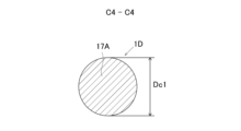
- FIG. 11 is an explanatory diagram illustrating a C4-C4 cross section of the guidewire of the fourth embodiment
- FIG. 27 is an explanatory diagram exemplifying an enlarged X region in FIG. 26;
- a guide wire is a medical device that is inserted into blood vessels and digestive organs by a doctor or the like and used for treatment and examination.
- distal side of the guidewire and guidewire components of the present invention
- distal side of the guidewire and guidewire components of the present invention
- distal side It is called the "rear end side” of the member.
- the distal end of the guidewire is the side that is inserted into the body before the guidewire is inserted into the body
- rearward end of the guidewire is the side that is operated by an operator such as a doctor (proximal). side).
- the end located on the distal side of the guide wire and each component of the guide wire is referred to as the "tip", and the part including the "tip” and extending halfway toward the rear end from the tip is the "tip". and described.
- the end located on the rear end side of the guide wire and each component member of the guide wire is referred to as the "rear end", and the portion including the “rear end” and extending halfway from the rear end toward the distal side is Described as “rear end”.
- the left-right direction in each of FIGS. 1, 2, 14, 18 and 22 is referred to as the longitudinal direction of the guide wire and each component of the guide wire. Also, the direction orthogonal to the longitudinal direction is called the radial direction of the guide wire and each component of the guide wire.
- each of FIGS. 1 to 27 includes a portion describing the relative size ratio of the guide wire and each component of the guide wire in a relative ratio different from the actual size.
- the outer diameter of the core shaft is the average value of all the measured outer diameters. Further, in the present application, that the outer diameter of the core shaft is substantially constant means that the maximum value of the outer diameter of the core shaft is 1.05 times or less the minimum value. In the present application, the outer diameter of the core shaft is measured by an outer diameter measuring device that uses a laser beam in a non-contact manner, and is measured at intervals of 0.15 mm or less in the longitudinal direction of the core shaft.
- FIG. 1 is an explanatory diagram illustrating the overall configuration of the guidewire 1A of the first embodiment.
- FIG. 1 illustrates the inside of the resin film 40 through the resin film 40 .
- FIG. 2 is an explanatory diagram illustrating the entire longitudinal section of the guidewire 1A of the first embodiment.
- the guide wire 1A of the first embodiment is a medical device that is used by percutaneously inserting it into a blood vessel to treat stenosis that has occurred in a lower limb blood vessel.
- the guide wire 1A has a core shaft 10A, a coil 20 covering part of the outer circumference of the core shaft 10A, and a resin film 40.
- a distal end portion of the coil 20 and a distal end portion of the core shaft 10A are fixed by a distal end side fixing portion 30 .
- the rear end portion of the coil 20 and the core shaft 10A are fixed by a rear end side fixing portion 31. As shown in FIG.
- the core shaft 10A is a member with an overall length of about 2000mm to about 4000mm.
- the core shaft 10A has a circular cross section and a maximum outer diameter of 0.58 mm or more and about 1.0 mm or less.
- the core shaft 10A has a small diameter portion 11, a main body portion 14A, and a large diameter portion 15 from the front end side to the rear end side.
- the small diameter portion 11 is a portion having an outer diameter smaller than the outer diameter Db1 of the main body portion 14A.
- the small diameter portion 11 has a distal straight portion 12 and a distal tapered portion 13 .
- the tip-side straight portion 12 constitutes the tip of the core shaft 10A, and its outer diameter Da1 (FIG. 3) is substantially constant along the longitudinal direction of the core shaft 10A.
- the tip-side tapered portion 13 is provided between the tip-side straight portion 12 and the body portion 14A, and has a tapered shape in which the outer diameter gradually increases toward the rear end side of the core shaft 10A.
- a part of the outer circumference of the small diameter portion 11 is covered with the coil 20 .
- a portion of the small-diameter portion 11 that is covered with the coil 20 is used as a reinforcing portion.
- the main body portion 14A is provided between the small diameter portion 11 and the large diameter portion 15 of the core shaft 10A, and its outer diameter Db1 (FIG. 4) is substantially constant along the longitudinal direction of the core shaft 10A.
- the large diameter portion 15 is a portion having an outer diameter larger than the outer diameter Db1 of the main body portion 14A.
- the large diameter portion 15 has a rear end tapered portion 16 and a rear end straight portion 17A.
- the rear end side tapered portion 16 is provided between the main body portion 14A and the rear end side straight portion 17A, and has a tapered shape in which the outer diameter gradually increases toward the rear end side of the core shaft 10A.
- the rear end side straight portion 17A constitutes the rear end of the core shaft 10A, and its outer diameter Dc1 (FIG. 5) is substantially constant along the longitudinal direction of the core shaft 10A.
- the large-diameter portion 15 functions as a high-rigidity portion having higher torsional rigidity than the main body portion 14A.
- La1 is the length of the small diameter portion 11 in the major axis direction.
- Lb1 is the length of the main body portion 14A in the longitudinal direction.
- Lc1 is the length of the large diameter portion 15 in the major axis direction.
- the body portion 14A is made of a nickel-titanium alloy.
- a nickel-titanium alloy is an alloy whose composition consists predominantly of nickel and titanium.
- a nickel-titanium alloy is an alloy having about 54% to about 57.0 wt% nickel and the remainder of which is titanium.
- Nickel-titanium alloys may also contain inclusions such as carbon, cobalt, copper, and chromium.
- Portions of the core shaft 10A other than the main body 14A can be made of materials such as nickel-titanium alloys, stainless steel alloys (SUS302, SUS304, SUS316, etc.), piano wires, nickel-chromium alloys, cobalt alloys, and tungsten.
- the body portion 14A and the portion of the core shaft 10A other than the body portion 14A are made of the same material, that is, a nickel-titanium alloy.
- the coil 20 is an example of the reinforcing body described in the claims of this application.
- the coil 20 is a tubular member that partially covers the outer circumference of the small diameter portion 11 .
- the coil 20 is formed by spirally winding a thin metal wire.
- the coil 20 can be made of materials such as nickel-titanium alloys, stainless steel alloys (SUS302, SUS304, SUS316, etc.), piano wires, nickel-chromium alloys, cobalt alloys, and tungsten.
- the distal end portion of the core shaft 10A and the distal end portion of the coil 20 are fixed by a distal end side fixing portion 30.
- a rear end portion of the core shaft 10 ⁇ /b>A and a rear end portion of the coil 20 are fixed by a rear end side fixing portion 31 .
- the distal end portion of the distal end side fixing portion 30 is formed to have a hemispherical shape.
- the front end side fixing portion 30 and the rear end side fixing portion 31 are formed by, for example, metal solder such as silver brazing or gold brazing, or an adhesive agent using epoxy resin.
- the resin film 40 is a thin film member that covers the entire length of the outer circumference of the guide wire 1A.
- the resin film 40 is made of, for example, polyvinyl alcohol, polyvinylpyrrolidone, polyethylene glycol, polyacrylamide, polyacrylic acid, sodium polyacrylate, polyurethane, polytetrafluoroethylene, perfluoroalkoxyalkane, poly(2-hydroxyethyl methacrylate), anhydrous Maleic acid copolymer, ethylene vinyl alcohol copolymer, 2-methacryloyloxyethylphosphorylcholine or its copolymer, (2-hydroxyethyl methacrylate)-styrene block copolymer, various synthetic polypeptides, collagen, hyaluronic acid, Formed by cellulosic polymers, mixtures thereof, and the like.
- FIG. 3 is an explanatory diagram illustrating the A1-A1 cross section of the guidewire 1A of the first embodiment.
- FIG. 3 shows a cross section of the distal straight portion 12 .
- FIG. 4 is an explanatory diagram illustrating the B1-B1 cross section of the guidewire 1A of the first embodiment.
- FIG. 4 shows a cross section of the body portion 14A.
- FIG. 5 is an explanatory diagram illustrating the C1-C1 cross section of the guidewire 1A of the first embodiment.
- FIG. 5 shows a cross section of the rear end side straight portion 17A.
- the cross section of the distal straight portion 12 is circular with an outer diameter Da1.
- the distal straight portion 12 is the thinnest portion of the core shaft 10A.
- the outer diameter Da1 of the distal end side straight portion 12 is smaller than the outer diameter Db1 of the main body portion 14A.
- the cross section of the body portion 14A is circular with an outer diameter Db1.
- the outer diameter Db1 of the main body portion 14A is larger than the outer diameter Da1 of the front end side straight portion 12 and smaller than the outer diameter Dc1 of the rear end side straight portion 17A.
- the rear end side straight portion 17A has a circular cross section with an outer diameter Dc1.
- the rear end side straight portion 17A is the thickest portion of the core shaft 10A.
- the outer diameter Dc1 of the rear end side straight portion 17A is larger than the outer diameter Db1 of the main body portion 14A.
- the outer diameter Db1 of the body portion 14A is set to 0.58 mm or more and 0.73 mm or less in consideration of the torque transmission performance and delivery performance of the guide wire used in the crossover method. Further, as will be described later, the outer diameter Db1 of the main body portion 14A is more preferably 0.58 mm or more and 0.71 mm or less.
- FIG. 6 is a diagram showing test results of a torque transmission performance test.
- five types (Samples 1 to 5) of guidewires having different body diameters Db1 were prepared. As shown in FIG. 6, the larger the sample number, the larger the outer diameter Db1 of the main body 14A.
- the "input angle" in FIG. 6 is the evaluation value of each sample obtained by the torque transmission performance test, and the "test result” is the result determined from the evaluation value of the "input angle".
- samples with an input angle of 315 degrees or less are labeled as “A1”
- samples with an input angle of greater than 315 degrees and less than or equal to 360 degrees are labeled with "A2”
- samples with an input angle of greater than 360 degrees are labeled with "B”.
- Fig. 7 is an explanatory diagram showing the test method of the torque transmission performance test.
- the blood vessel model T4 for torque performance test is provided with a simulated blood vessel T5 that simulates the CIA and its surrounding blood vessels.
- the torque transmission performance test is performed by the following procedure using the torque transmission performance test blood vessel model T4.
- the catheter T3 is arranged over the entire length of the simulated blood vessel T5.
- the guide wire 1S which is one of the samples 1 to 5
- the rear end of the guide wire 1S is connected to the guide wire rotation unit T1, and rotated in the direction of rotation T2 in FIG. 7 by the rotation unit T1.
- the measurement marker T6 attached to the tip of the guide wire 1S is photographed by the camera T7, and the input angle of the rotation unit T1 when the rotation angle reaches 180 degrees is recorded.
- the "input angle" column in FIG. 6 shows the input angle of the rotation unit T1 when the rotation angle of the measurement marker T6 is 180 degrees for each of the samples 1-5.
- the rotation angle of the measurement marker T6 corresponds to the rotation angle of the distal end of the guidewire 1S.
- the input angle of the rotation unit T1 corresponds to the rotation angle when the operator rotates the rear end of the guide wire 1S.
- the samples with test results A1 and A2 were judged to have good torque transmission performance.
- the sample with test results A1 was judged to be better. This criterion is based on the fact that when the operator rotates the distal end of the guidewire to determine the direction of movement at a bifurcation of a blood vessel, one finger operation of the operator (the rear end of the guidewire is rotated approximately once) It was determined in consideration of the fact that the tip of the guide wire is required to have torque transmission performance to the extent that it rotates half a turn depending on the operation).
- A1 is a sample that exhibits better torque transmission performance, such that the operator can turn the distal end of the guidewire half a turn without turning the posterior end of the guidewire once.
- A2 is a sample in which the tip of the tip can be rotated halfway. From the test results, it can be determined that samples 3 and 4 have good torque transmission performance, and samples 1 and 2 have better torque transmission performance. From this, when the outer diameter Db1 of the main body portion 14A is 0.73 mm or less, the torque transmission performance is good, and when the outer diameter Db1 of the main body portion 14A is 0.71 mm or less, the torque transmission performance is better. can be determined to be
- FIG. 8 is a diagram showing test results of a delivery performance test.
- the delivery performance test as shown in FIG. 8, five types (Samples 6 to 10) of guidewires having different body diameters Db1 were prepared. As shown in FIG. 8, the larger the sample number, the larger the outer diameter Db1 of the main body 14A.
- the test method and evaluation method of the delivery performance test will be described later with reference to FIGS. 9 to 11.
- FIG. "Test results" in FIG. 8 are the results evaluated by the evaluation method described later.
- the sample in which the situation shown in FIG. 10 occurred at the time of delivery was designated as "A”
- the sample in which the state shown in FIG. 11 occurred was designated as "B”. Samples with a test result of A show good delivery performance.
- a sample with a test result of B indicates that the delivery performance was not good.
- FIG. 9 is an explanatory diagram showing the test method of the delivery performance test.
- FIG. 10 is an explanatory diagram showing an example of good delivery performance in the delivery performance test.
- FIG. 11 is an explanatory diagram showing an example of poor delivery performance in the delivery performance test.
- FIG. 12 shows measurement results of the bending load of the catheter used in the delivery performance test.
- the delivery performance test blood vessel model T8 is provided with a simulated blood vessel T9 that imitates the shape of the CIA and the blood vessels near the CIA.
- the delivery performance test is conducted according to the following procedure. First, the guide wire 1S, which is one of the samples 6 to 10, is inserted into the simulated blood vessel T9 through the opening T11 provided at the end of the simulated blood vessel T9, and the main body portion is placed in the curved portion 100 of the CIA. left in place. Next, the catheter T10 is inserted along the guide wire 1A through the opening T11 into the simulated blood vessel T9. In this test, the catheter T10 used was Terumo Corporation's DESTINATION (registered trademark), which is a catheter commonly used in lower extremity vascular treatment.
- Catheter T10 has an inner diameter of approximately 2.24 mm and an outer diameter of approximately 2.79 mm.
- FIG. 12 shows the bending load corresponding to the distance from the tip of the catheter T10.
- the catheter T10 is then advanced over the bend 100 of the CIA toward the EIA.
- the catheter T10 can be advanced beyond the curved portion 100 of the CIA without the position of the main body of the indwelling guidewire 1A changing significantly by moving the catheter T10.
- the resulting sample was judged to have good delivery performance.
- the position of the main body of the indwelling guidewire 1S is greatly changed by attempting to advance the catheter T10 toward the EIA, and the main body and the catheter T10 move toward the AA. It was judged that the delivery performance was not good for the sample in which the catheter T10 could not be advanced beyond the curved portion 100 of the CIA by being pushed out.
- FIG. 13 is an explanatory diagram illustrating a state in which the guidewire 1A is indwelled in the lower limb blood vessel of the human body by the crossover method.
- the main body having the outer diameter Db1 obtained in the torque transmission performance test and the delivery performance test described above when the guidewire is indwelled in the blood vessel of the lower limb by the crossover method is located at the curved portion of the blood vessel of the lower limb.
- blood vessels of the lower extremities are formed in the order AA (abdominal aorta), CIA (common iliac artery), EIA (external iliac artery), and CFA (common femoral artery) from the abdomen toward the toes. It is CFA branches into SFA (superficial femoral artery) and DFA (deep femoral artery), and SFA is pop. A (popliteal artery), Pop. A is ATA (anterior tibial artery), PTA (posterior tibial artery), Pero. It branches into A (peroneal artery).
- the BK region in FIG. 13 includes ATA, PTA and Pero. Lower extremity vessels including A are shown.
- CIA, EIA, and CFA tend to have highly curved vessels such as the curved portion 100 of the CIA.
- the X region shown in FIG. 13 indicates a region containing blood vessels with a large degree of curvature.
- L1 shown in FIG. 13 is the length from the end of AA to the end of CFA. L1 is approximately 150 mm according to CT scan data obtained from the patient.
- the puncture portion 101 which is the position where the guide wire 1A is inserted in the crossover method, is often near the distal end of the CFA, the distance from the puncture portion 101 to the distal end of the AA is approximately the same as L1.
- the length from the puncture portion 101 to the end of the CFA on the other leg is approximately 300 mm.
- L2 extends from the end of CFA to Pop. It is the length up to the end of A.
- L2 is about 350 mm to about 450 mm according to CT scan data obtained from the patient. For example, ATA, PTA or Pero.
- CT scan data obtained from the patient. For example, ATA, PTA or Pero.
- the length of the core shaft 10A of the guidewire 1A is about 350 mm from the tip.
- a range of 350 mm or more and about 650 mm or less is arranged in the X region.
- the X region should be about 350 mm or more from the tip of the core shaft 10A of the guide wire 1A and about 750 mm or more. It is a part that is likely to be placed.
- the portion of the core shaft 10A that is arranged in the X region changes depending on the location of the constricted portion Le and the location of the puncture portion 101 .
- the inventors identified a position in the human body where the puncture site 101 can be easily set, and made it so that the tip of the guide wire reaches the BK region where the constriction Le is likely to occur and torque transmission and delivery are most required. The above setting was performed so that the main body portion 14A is positioned in the X region even when the guidewire is placed in the X region.
- the portion of the core shaft 10A that is 350 mm or more and 750 mm or more from the distal end is the main body portion 14A.
- the outer diameter Db1 of the body portion 14A is 0.73 mm or less.
- the outer diameter Db1 of the body portion 14A may be 0.71 mm or less.
- the amount of strain due to bending deformation is further reduced, and the contact resistance that the main body portion 14A receives from the inner wall of the blood vessel is further reduced.
- 1A can exhibit better torque transmission performance even in the crossover method.
- the outer diameter Db1 of the body portion 14A is 0.58 mm or more, the guidewire 1A can exhibit good delivery performance even in the crossover method.
- the body portion 14A is made of a nickel-titanium alloy. As a result, deterioration of operability due to deformation of the core shaft 10A can be reduced even when the main body is inserted into the CIA, EIA, and CFA, which have relatively large degrees of curvature.
- the outer diameter Db1 of the body portion 14A is substantially the same in length in the longitudinal direction.
- a tapered shape in which the outer diameter Db1 of the main body portion 14A gradually increases along the long axis direction a stepped shape in which the outer diameter Db1 of the main body portion 14A increases for each fixed length in the long axis direction, etc.
- good torque transmission performance and delivery performance can be exhibited regardless of the relative positional relationship between the body portion 14A and the blood vessel. In other words, good torque transmission performance and delivery performance are achieved in both cases where the front end side and the rear end side of the body portion 14A are arranged in the CIA, EIA, and CFA, which have relatively large degrees of curvature. can be demonstrated.
- the guide wire 1A of the first embodiment has a resin film 40.
- the sliding resistance between the outer peripheral surface of the guidewire 1A and the inside of the blood vessel can be reduced, and the slipperiness of the guidewire 1A inside the blood vessel is improved.
- the guidewire 1A of the first embodiment has a coil 20.
- the strength of the reinforcing portion of the guide wire 1A that is inserted into the narrower blood vessel at the distal end can be improved by the reinforcing body.
- the reinforcing portion is the portion of the small diameter portion 11 whose outer circumference is covered with the coil 20 .
- the guide wire 1A has the small-diameter portion 11, the flexibility of the distal end side of the guide wire 1A can be further improved.
- the guide wire 1A has a distal side tapered portion 13. As shown in FIG. As a result, the flexural rigidity of the core shaft 10A can be gradually increased from the distal end straight portion 11 toward the main body portion 14A.
- the guidewire 1A also has a large diameter portion 15 .
- the torsional rigidity of the rear end portion of the guide wire 1A is high, so the torque transmission performance can be further improved.
- the guide wire 1A has a rear end tapered portion 16. As shown in FIG. As a result, the flexural rigidity of the core shaft 10A can be gradually increased from the body portion 14A toward the rear end side straight portion 17A, and stress is concentrated on the portion between the body portion 14A and the rear end side straight portion 17A. Therefore, it is possible to reduce the possibility that the core shaft 10A will kink.
- FIG. 14 is an explanatory view exemplifying the longitudinal section of the entire guidewire 1B of the second embodiment.
- FIG. 15 is an explanatory diagram illustrating the A2-A2 cross section of the guide wire 1B of the second embodiment.
- FIG. 16 is an explanatory diagram illustrating the B2-B2 cross section of the guide wire 1B of the second embodiment.
- FIG. 17 is an explanatory diagram illustrating the C2-C2 cross section of the guide wire 1B of the second embodiment.
- the guidewire 1B of the second embodiment differs from the guidewire 1A of the first embodiment in that it does not have a large diameter portion 15 (Fig. 2). Portions other than the large diameter portion 15 of the guide wire 1B of the second embodiment are common to the guide wire 1A of the first embodiment.
- the guide wire 1B has a core shaft 10B with a rear end side straight portion 17B.
- the rear end side straight portion 17B is a portion that is on the rear end side of the main body portion 14A and constitutes the rear end portion of the core shaft 10B.
- Lc2 is the length in the longitudinal direction of the rear end side straight portion 17B.
- the outer diameter Dc2 of the rear end side straight portion 17B is substantially the same as the outer diameter Db1 of the main body portion 14A.
- the guide wire 1B of the second embodiment described above can also exhibit the same effects as the guide wire 1A of the first embodiment. Since the outer diameter Dc2 of the rear end side straight portion 17B is substantially the same as the outer diameter Db1 of the main body portion 14A, for example, CIA, EIA, and CFA, which have a large degree of curvature, are longer than expected, and are located on the rear end side of the main body portion 14A. Even when the core shaft 10B is placed in those blood vessels, good torque transmission performance and delivery performance can be exhibited.
- FIG. 18 is an explanatory view exemplifying the longitudinal section of the entire guidewire 1C of the third embodiment.
- FIG. 19 is an explanatory diagram illustrating the A3-A3 cross section of the guidewire 1C of the third embodiment.
- FIG. 20 is an explanatory diagram illustrating the B3-B3 cross section of the guidewire 1C of the third embodiment.
- FIG. 21 is an explanatory view exemplifying the C3-C3 cross section of the guide wire 1C of the third embodiment.
- the rear end side straight portion 17C of the guidewire 1C is formed of a different material having higher torsional rigidity than the main portion 14A. Different in Parts other than the rear end side straight portion 17C of the guide wire 1C of the third embodiment are common to the guide wire 1A of the first embodiment.
- the rear end side straight portion 17C is a portion depicted in FIG. 18 with a hatching pattern different from that of the main body portion 14A.
- the guide wire 1C has a core shaft 10C having a rear end side straight portion 17C.
- the rear end side straight portion 17C is a portion that is on the rear end side of the main body portion 14A and constitutes the rear end portion of the core shaft 10C.
- the outer diameter Dc3 of the rear end side straight portion 17C is substantially the same as the outer diameter Db1 of the main body portion 14A.
- Lc3 is the length in the longitudinal direction of the rear end side straight portion 17C.
- the rear end side straight portion 17C is made of a different material having a higher lateral elastic modulus than the material of the main body portion 14A.
- the rear straight portion 17C can be made of materials such as stainless alloy (SUS302, SUS304, SUS316, etc.), piano wire, nickel-chromium alloy, cobalt alloy, and tungsten.
- the rear end portion of the main body portion 14A and the front end portion of the rear end side straight portion 17C are joined by a method such as soldering, adhesive, or welding.
- the guidewire 1C of the third embodiment described above can also exhibit the same effects as the guidewire 1A of the first embodiment.
- the lateral elastic modulus of the material of the rear end side straight portion 17C is higher than that of the material of the main body portion 14A, the torsional rigidity of the rear end portion of the core shaft 10C is higher, resulting in better torque transmission performance. can demonstrate.
- FIG. 22 is an explanatory view exemplifying the longitudinal section of the entire guide wire 1D of the fourth embodiment.
- FIG. 23 is an explanatory diagram illustrating the A4-A4 section of the guide wire 1D of the fourth embodiment.
- FIG. 24 is an explanatory diagram illustrating the B4-B4 cross section of the guide wire 1D of the fourth embodiment.
- FIG. 25 is an explanatory diagram illustrating the C4-C4 cross section of the guide wire 1D of the fourth embodiment.
- the body portion 14D of the guidewire 1D has a tapered shape in which the outer diameter Db4 gradually increases toward the rear end side of the core shaft 10D. different in that. Parts other than the main body portion 14D of the guide wire 1D of the fourth embodiment are common to the guide wire 1A of the first embodiment.
- the guidewire 1D has a core shaft 10D with a body portion 14D.
- the outer diameter Db4 of the body portion 14D gradually increases toward the rear end side of the core shaft 10D.
- Lb4 is the length of the main body portion 14D in the longitudinal direction.
- the guide wire 1D of the fourth embodiment described above can also exhibit the same effects as the guide wire 1A of the first embodiment. Since the main body portion 14D of the guide wire 1D has a tapered shape, the flexural rigidity of the core shaft 10D can be gradually increased from the small diameter portion 11 toward the large diameter portion 15. As shown in FIG. Therefore, it is possible to reduce the possibility that stress concentrates on the body portion 14D and the body portion 14D kinks.
- the distal side straight portion 12, the main body portion 14A, and the rear end side straight portion 17A are straight, and the distal side tapered portion 13 and the rear end side tapered portion 16 are formed on the distal side.
- the outer diameter of each portion of the core shaft may be a straight shape in which the outer diameter is substantially constant in the long axis direction, or a tapered shape in which the outer diameter gradually increases or decreases toward the rear end side of the core shaft. It's okay.
- the outer diameter of each portion of the core shaft may have a stepped shape in which the outer diameter increases or decreases for each fixed length in the longitudinal direction of the core shaft.
- the cross section of the core shaft 10 of the guide wire 1A of the first embodiment is circular.
- the cross section of the core shaft 10 does not have to be circular, and may be rectangular such as square or rectangular, or triangular.
- the cross section of the distal straight portion 12 of the guide wire 1A is anisotropic in the direction in which deformation is likely to occur, such as a rectangle, the operator can easily shape the distal end portion of the guide wire. .
- the torsional rigidity is higher on the rear end side than on the front end side.
- the core shaft may be configured to have greater torsional stiffness on the distal end side in its longitudinal direction.
- the torsional rigidity of the small diameter portion may be higher than the torsional rigidity of the body portion.
- the resin film 40 of the first embodiment is composed of a single type, and its characteristics do not change.
- the properties of the resin film covering the outer circumference of the core shaft may change in the longitudinal direction of the core shaft.
- the main body and the large diameter portion may be covered with a hydrophobic resin film, or only the large diameter portion may be covered with a hydrophobic resin film.
- a guide wire whose large diameter portion is covered with a hydrophobic resin film can have sufficient frictional force to allow an operator to easily grip the guide wire while having the sliding performance of the guide wire.
- the entire body portion may be covered with resin films having the same properties, or different portions of the body portion may be covered with a plurality of resin films having different properties.
- part or all of the core shaft may be covered with a plurality of layers of resin.
- the outer circumferences of the coil and the main body may be covered with a resin film containing urethane, and the outer circumference of the resin film containing urethane may be covered with a hydrophilic resin film.
- the reinforcing body of the first embodiment is formed by spirally winding a thin metal wire.
- the reinforcing body may be a hollow coil formed by twisting a plurality of metal filaments.
- the guidewire may not have a reinforcing body.
- the outer circumference of the tip portion of the core shaft may be covered with a resin film.
Abstract
This guide wire comprises a core shaft. A main body of the guide wire, which is a portion 350-750 mm from the tip of the core shaft, is made of nickel-titanium alloy, and the outer diameter of the main body is 0.58-0.73 mm.
Description
本発明は、ガイドワイヤに関する。
The present invention relates to guidewires.
従来から、血管に発生した狭窄部を治療するために経皮的に血管内に挿入して使用される医療器具として、ガイドワイヤが知られている。このガイドワイヤに関して、特許文献1には、下肢血管の治療に用いられるガイドワイヤが記載されている。
A guide wire is conventionally known as a medical device that is used by percutaneously inserting it into a blood vessel in order to treat a stenosis that has occurred in the blood vessel. Regarding this guide wire, Patent Literature 1 describes a guide wire used for treatment of lower extremity blood vessels.
ガイドワイヤを用いて下肢血管の狭窄部を治療するための方法として、クロスオーバー法という手法が採用されている。図26は、人体の下肢血管を例示した説明図である。図27は、図26におけるX領域を拡大して例示した説明図である。クロスオーバー法は、ガイドワイヤ1を、狭窄部Leのある脚ではない方の脚の大腿部付近の穿刺部101から血管内に挿入し、総腸骨動脈(以下、CIAとする)を通過させて狭窄部Leのある方の脚まで進め、狭窄部Leまで到達させる方法である。図26には、人体の下肢血管にガイドワイヤ1が挿入された状態が例示されている。ここでは、膝下領域(以下、BK領域とする)に含まれる前脛骨動脈(以下、ATAとする)に狭窄部Leが発生しているものとする。ガイドワイヤ1は、まず、狭窄部Leが発生した脚ではない方の脚の大腿部付近の穿刺部101から経皮的に体内の血管に挿入される。ガイドワイヤ1は、CIAを腹部大動脈(以下、AAとする)に向かって進み、CIAの湾曲部100を通過して、さらにCIA内を狭窄部Leに向かって進む。ガイドワイヤ1は、外腸骨動脈(以下、EIAとする)、総大腿動脈(以下、CFAとする)、浅大腿動脈(以下、SFAとする)および膝窩動脈(以下、Pop.Aとする)を通過し、前脛骨動脈(ATA)に到達する。ガイドワイヤ1は狭窄部Leの付近に留置され、ガイドワイヤ1に沿ってカテーテルなどの併用器具が血管内に挿入され、狭窄部Leの治療が行われる。このように、クロスオーバー法においては、ガイドワイヤが下肢血管においても比較的湾曲度合いの大きいCIA、EIAおよびCFAを通過するため、手技者がガイドワイヤを回転させる操作をガイドワイヤの先端まで効率よく伝える性能(トルク伝達性能)に、なお改善の余地があった。また、ガイドワイヤに沿って血管内に挿入されるカテーテルなどの併用器具を、特に湾曲度合いの大きいCIAを通過させるための性能(デリバリー性能)にも、なお改善の余地があった。
A technique called the crossover method is adopted as a method for treating stenosis of lower extremity blood vessels using a guide wire. FIG. 26 is an explanatory diagram illustrating blood vessels of the lower extremities of the human body. FIG. 27 is an explanatory diagram exemplifying the X area in FIG. 26 in an enlarged manner. In the crossover method, the guide wire 1 is inserted into the blood vessel from the puncture site 101 near the thigh of the leg other than the leg having the stenosis Le, and passes through the common iliac artery (hereinafter referred to as the CIA). In this method, the leg is moved to the leg on which the constricted portion Le exists, and the leg is reached to the constricted portion Le. FIG. 26 illustrates a state in which the guide wire 1 is inserted into the blood vessels of the lower extremities of the human body. Here, it is assumed that a stenosed portion Le occurs in the anterior tibial artery (hereinafter referred to as ATA) included in the below-the-knee area (hereinafter referred to as BK area). The guide wire 1 is first percutaneously inserted into a blood vessel in the body from a puncture site 101 near the thigh of the leg other than the leg where the constriction Le occurs. The guide wire 1 advances through the CIA toward the abdominal aorta (hereinafter referred to as AA), passes through the curved portion 100 of the CIA, and further advances through the CIA toward the constricted portion Le. The guidewire 1 is used for the external iliac artery (hereinafter referred to as EIA), common femoral artery (hereinafter referred to as CFA), superficial femoral artery (hereinafter referred to as SFA) and popliteal artery (hereinafter referred to as Pop.A ) to reach the anterior tibial artery (ATA). The guidewire 1 is left in the vicinity of the stenosis Le, and a combined instrument such as a catheter is inserted into the blood vessel along the guidewire 1 to treat the stenosis Le. Thus, in the crossover method, the guidewire passes through the CIA, EIA, and CFA, which are relatively curved even in the blood vessels of the lower extremities. There was still room for improvement in transmission performance (torque transmission performance). In addition, there is still room for improvement in the performance (delivery performance) for allowing a combined instrument such as a catheter inserted into a blood vessel along a guide wire to pass through the CIA, which has a particularly large degree of curvature.
本発明は、上述した課題を解決するためになされたものであり、下肢血管の狭窄部を治療するために使用されるガイドワイヤにおいて、クロスオーバー法による治療時のトルク伝達性能と、デリバリー性能の両方に優れるガイドワイヤの提供を目的とする。
The present invention has been made in order to solve the above-described problems. An object is to provide a guide wire that is excellent in both.
本発明は、上述の課題の少なくとも一部を解決するためになされたものであり、以下の形態として実現することが可能である。
The present invention has been made to solve at least part of the above problems, and can be implemented as the following forms.
(1)本発明の一形態によれば、ガイドワイヤが提供される。このガイドワイヤは、コアシャフトを備え、コアシャフトは、先端から350mm以上かつ750mm以下の部分である本体部がニッケルチタン合金からなり、本体部の外径が0.58mm以上かつ0.73mm以下である。
(1) According to one aspect of the present invention, a guidewire is provided. This guide wire has a core shaft, the main body of which is 350 mm or more and 750 mm or less from the tip is made of a nickel-titanium alloy, and the main body has an outer diameter of 0.58 mm or more and 0.73 mm or less. be.
この構成によれば、コアシャフトの先端から350mm以上かつ750mm以下の部分である本体部がニッケルチタン合金により形成され、かつ、外径が0.58mm以上かつ0.73mm以下となっているため、クロスオーバー法による治療時のトルク伝達性能と、デリバリー性能の両方に優れるガイドワイヤを提供することができる。具体的には、本体部がニッケルチタン合金により形成されているため、クロスオーバー法によって、本体部が湾曲度合いの大きいCIA、EIAおよびCFAを通過した場合においても、コアシャフトの変形による操作性の悪化を低減することができる。また、本体部の外径が0.58mm以上であることにより、本体部をCIA付近に配置することで、カテーテルなどの併用器具をガイドワイヤに沿って片方の脚から他方の脚に容易に進めることができる。また、本体部が0.73mm以下であることにより、本体部をCIA付近に配置することで、手技者の回転操作を効率よくガイドワイヤの先端まで伝えることができる。また、本体部がコアシャフトの先端から350mm以上かつ750mm以下の範囲にあることにより、患者の血管の長さによらずに本体部をCIA付近に配置することが可能となり、ガイドワイヤのトルク伝達性能とデリバリー性能をより多くの患者で向上させることができる。
According to this configuration, the main body, which is a portion of 350 mm or more and 750 mm or less from the tip of the core shaft, is made of a nickel-titanium alloy and has an outer diameter of 0.58 mm or more and 0.73 mm or less. It is possible to provide a guide wire that is excellent in both torque transmission performance during treatment by the crossover method and delivery performance. Specifically, since the main body is made of a nickel-titanium alloy, even when the main body passes through CIA, EIA, and CFA, which have a large degree of curvature, the operability due to the deformation of the core shaft is improved by the crossover method. Exacerbation can be reduced. In addition, since the main body has an outer diameter of 0.58 mm or more, by placing the main body in the vicinity of the CIA, a combined instrument such as a catheter can be easily advanced from one leg to the other along the guide wire. be able to. In addition, since the main body is 0.73 mm or less, the rotating operation of the operator can be efficiently transmitted to the distal end of the guide wire by arranging the main body near the CIA. In addition, since the main body is in the range of 350 mm or more and 750 mm or less from the tip of the core shaft, the main body can be placed near the CIA regardless of the length of the patient's blood vessel, and torque transmission of the guide wire Performance and delivery performance can be improved in more patients.
(2)上記形態のガイドワイヤにおいて、コアシャフトは、本体部の外径が0.71mm以下であってもよい。
(2) In the guidewire of the above configuration, the outer diameter of the main body of the core shaft may be 0.71 mm or less.
この構成によれば、コアシャフトの先端から350mm以上かつ750mm以下の部分である本体部の外径が0.71mm以下となっているため、クロスオーバー法による治療時のトルク伝達性能のさらなる向上を図ることができる。
According to this configuration, since the outer diameter of the main body, which is the portion of 350 mm or more and 750 mm or less from the tip of the core shaft, is 0.71 mm or less, the torque transmission performance during treatment by the crossover method can be further improved. can be planned.
なお、本発明は、種々の態様で実現することが可能であり、例えば、ガイドワイヤ、ガイドワイヤの製造方法、カテーテルの製造方法、内視鏡、ダイレータ、などの形態で実現することができる。
The present invention can be implemented in various aspects, for example, in the form of a guidewire, a guidewire manufacturing method, a catheter manufacturing method, an endoscope, a dilator, and the like.
ガイドワイヤは、医師等によって血管や消化器官に挿入され、治療や検査に用いられる医療器具である。
A guide wire is a medical device that is inserted into blood vessels and digestive organs by a doctor or the like and used for treatment and examination.
以下では、図1、図2、図14、図18および図22の各図における左側を本発明のガイドワイヤおよびガイドワイヤの各構成部材の「先端側」と呼び、右側をガイドワイヤおよび各構成部材の「後端側」と呼ぶ。ガイドワイヤの先端側は、ガイドワイヤが体内に挿入される際に先行して体内に挿入される側であり、ガイドワイヤの後端側は、医師等の手技者によって操作される側(近位側)である。また、ガイドワイヤ及びガイドワイヤの各構成部材の、先端側に位置する端部を「先端」と記載し、「先端」を含み先端から後端側に向かって中途まで延びる部位を「先端部」と記載する。同様に、ガイドワイヤ及びガイドワイヤの各構成部材の、後端側に位置する端部を「後端」と記載し、「後端」を含み後端から先端側に向かって中途まで延びる部位を「後端部」と記載する。
1, 2, 14, 18 and 22 are referred to as the "distal side" of the guidewire and guidewire components of the present invention, and the right side of the guidewire and components are referred to as the "distal side". It is called the "rear end side" of the member. The distal end of the guidewire is the side that is inserted into the body before the guidewire is inserted into the body, and the rearward end of the guidewire is the side that is operated by an operator such as a doctor (proximal). side). In addition, the end located on the distal side of the guide wire and each component of the guide wire is referred to as the "tip", and the part including the "tip" and extending halfway toward the rear end from the tip is the "tip". and described. Similarly, the end located on the rear end side of the guide wire and each component member of the guide wire is referred to as the "rear end", and the portion including the "rear end" and extending halfway from the rear end toward the distal side is Described as "rear end".
図1、図2、図14、図18および図22の各図における左右方向をガイドワイヤおよびガイドワイヤの各構成部材の長軸方向と呼ぶ。また、長軸方向に対して直交する方向をガイドワイヤおよびガイドワイヤの各構成部材の径方向と呼ぶ。
The left-right direction in each of FIGS. 1, 2, 14, 18 and 22 is referred to as the longitudinal direction of the guide wire and each component of the guide wire. Also, the direction orthogonal to the longitudinal direction is called the radial direction of the guide wire and each component of the guide wire.
図1から図27の各図は、説明の便宜上、ガイドワイヤおよびガイドワイヤの各構成部材の大きさの相対比を実際とは異なる相対比で記載している部分を含んでいる。
For convenience of explanation, each of FIGS. 1 to 27 includes a portion describing the relative size ratio of the guide wire and each component of the guide wire in a relative ratio different from the actual size.
本願においてコアシャフトの外径とは、その測定された全ての外径の平均値とする。また、本願においてコアシャフトの外径が略一定であるとは、コアシャフトの外径のうちの、最大値が最小値の1.05倍以下であることを意味する。本願においては、コアシャフトの外径はレーザー光により非接触式で測定する外径測定器により測定され、コアシャフトの長軸方向において0.15mm以下の間隔で測定される。
In this application, the outer diameter of the core shaft is the average value of all the measured outer diameters. Further, in the present application, that the outer diameter of the core shaft is substantially constant means that the maximum value of the outer diameter of the core shaft is 1.05 times or less the minimum value. In the present application, the outer diameter of the core shaft is measured by an outer diameter measuring device that uses a laser beam in a non-contact manner, and is measured at intervals of 0.15 mm or less in the longitudinal direction of the core shaft.
<第1実施形態>
図1は、第1実施形態のガイドワイヤ1Aの全体構成を例示した説明図である。図1では、樹脂膜40を透過して樹脂膜40の内部が例示されている。図2は、第1実施形態のガイドワイヤ1Aの全体の縦断面を例示した説明図である。 <First Embodiment>
FIG. 1 is an explanatory diagram illustrating the overall configuration of theguidewire 1A of the first embodiment. FIG. 1 illustrates the inside of the resin film 40 through the resin film 40 . FIG. 2 is an explanatory diagram illustrating the entire longitudinal section of the guidewire 1A of the first embodiment.
図1は、第1実施形態のガイドワイヤ1Aの全体構成を例示した説明図である。図1では、樹脂膜40を透過して樹脂膜40の内部が例示されている。図2は、第1実施形態のガイドワイヤ1Aの全体の縦断面を例示した説明図である。 <First Embodiment>
FIG. 1 is an explanatory diagram illustrating the overall configuration of the
第1実施形態のガイドワイヤ1Aは、下肢血管に発生した狭窄部を治療するために経皮的に血管内に挿入して使用される医療器具である。ガイドワイヤ1Aは、コアシャフト10Aと、コアシャフト10Aの外周の一部を覆うコイル20と、樹脂膜40と、を有する。コイル20の先端部とコアシャフト10Aの先端部は、先端側固定部30により固定されている。また、コイル20の後端部とコアシャフト10Aは、後端側固定部31により固定されている。
The guide wire 1A of the first embodiment is a medical device that is used by percutaneously inserting it into a blood vessel to treat stenosis that has occurred in a lower limb blood vessel. The guide wire 1A has a core shaft 10A, a coil 20 covering part of the outer circumference of the core shaft 10A, and a resin film 40. A distal end portion of the coil 20 and a distal end portion of the core shaft 10A are fixed by a distal end side fixing portion 30 . Further, the rear end portion of the coil 20 and the core shaft 10A are fixed by a rear end side fixing portion 31. As shown in FIG.
コアシャフト10Aは、全長が約2000mmから約4000mmの部材である。コアシャフト10Aの横断面は円形であり、その最大外径は0.58mm以上であり約1.0mm以下である。コアシャフト10Aは、その先端側から後端側に向かって、小径部11、本体部14Aおよび、大径部15を有している。小径部11は、本体部14Aの外径Db1よりも小さい外径を有する部分である。小径部11は、先端側ストレート部12と、先端側テーパ部13を有する。先端側ストレート部12は、コアシャフト10Aの先端を構成し、その外径Da1(図3)は、コアシャフト10Aの長軸方向に沿って略一定である。先端側テーパ部13は、先端側ストレート部12と本体部14Aの間に設けられ、コアシャフト10Aの後端側に向かって外径が徐々に大きくなるテーパ形状である。小径部11の外周の一部は、コイル20によって覆われている。小径部11のうち、コイル20に覆われている部分を補強部とする。本体部14Aは、コアシャフト10Aの小径部11と、大径部15の間に設けられ、その外径Db1(図4)は、コアシャフト10Aの長軸方向に沿って略一定である。大径部15は、本体部14Aの外径Db1よりも大きい外径を有する部分である。大径部15は、後端側テーパ部16と、後端側ストレート部17Aを有する。後端側テーパ部16は、本体部14Aと、後端側ストレート部17Aの間に設けられ、コアシャフト10Aの後端側に向かって外径が徐々に大きくなるテーパ形状である。後端側ストレート部17Aは、コアシャフト10Aの後端を構成し、その外径Dc1(図5)は、コアシャフト10Aの長軸方向に沿って略一定である。大径部15は、本体部14Aよりも捻り剛性が高い高剛性部として機能する。
The core shaft 10A is a member with an overall length of about 2000mm to about 4000mm. The core shaft 10A has a circular cross section and a maximum outer diameter of 0.58 mm or more and about 1.0 mm or less. The core shaft 10A has a small diameter portion 11, a main body portion 14A, and a large diameter portion 15 from the front end side to the rear end side. The small diameter portion 11 is a portion having an outer diameter smaller than the outer diameter Db1 of the main body portion 14A. The small diameter portion 11 has a distal straight portion 12 and a distal tapered portion 13 . The tip-side straight portion 12 constitutes the tip of the core shaft 10A, and its outer diameter Da1 (FIG. 3) is substantially constant along the longitudinal direction of the core shaft 10A. The tip-side tapered portion 13 is provided between the tip-side straight portion 12 and the body portion 14A, and has a tapered shape in which the outer diameter gradually increases toward the rear end side of the core shaft 10A. A part of the outer circumference of the small diameter portion 11 is covered with the coil 20 . A portion of the small-diameter portion 11 that is covered with the coil 20 is used as a reinforcing portion. The main body portion 14A is provided between the small diameter portion 11 and the large diameter portion 15 of the core shaft 10A, and its outer diameter Db1 (FIG. 4) is substantially constant along the longitudinal direction of the core shaft 10A. The large diameter portion 15 is a portion having an outer diameter larger than the outer diameter Db1 of the main body portion 14A. The large diameter portion 15 has a rear end tapered portion 16 and a rear end straight portion 17A. The rear end side tapered portion 16 is provided between the main body portion 14A and the rear end side straight portion 17A, and has a tapered shape in which the outer diameter gradually increases toward the rear end side of the core shaft 10A. The rear end side straight portion 17A constitutes the rear end of the core shaft 10A, and its outer diameter Dc1 (FIG. 5) is substantially constant along the longitudinal direction of the core shaft 10A. The large-diameter portion 15 functions as a high-rigidity portion having higher torsional rigidity than the main body portion 14A.
第1実施形態のガイドワイヤ1Aにおいて、La1は、小径部11の長軸方向の長さである。Lb1は、本体部14Aの長軸方向の長さである。Lc1は、大径部15の長軸方向の長さである。
In the guidewire 1A of the first embodiment, La1 is the length of the small diameter portion 11 in the major axis direction. Lb1 is the length of the main body portion 14A in the longitudinal direction. Lc1 is the length of the large diameter portion 15 in the major axis direction.
本体部14Aは、ニッケルチタン合金からなる。ニッケルチタン合金とは、その組成の主要部分がニッケルとチタンからなる合金である。例えばニッケルチタン合金とは、ニッケルを約54%から約57.0wt%有し、その他の部分がチタンからなる合金である。またニッケルチタン合金は、カーボン、コバルト、銅、クロムなどの介在物を含む場合がある。コアシャフト10Aのうち本体部14A以外の部分は、例えば、ニッケルチタン合金、ステンレス合金(SUS302、SUS304、SUS316等)、ピアノ線、ニッケル-クロム系合金、コバルト合金、タングステン等の材料で形成できる。本実施形態では、本体部14Aとコアシャフト10Aのうち本体部14A以外の部分は同じ材料、すなわち、ニッケルチタン合金によって形成されている。
The body portion 14A is made of a nickel-titanium alloy. A nickel-titanium alloy is an alloy whose composition consists predominantly of nickel and titanium. For example, a nickel-titanium alloy is an alloy having about 54% to about 57.0 wt% nickel and the remainder of which is titanium. Nickel-titanium alloys may also contain inclusions such as carbon, cobalt, copper, and chromium. Portions of the core shaft 10A other than the main body 14A can be made of materials such as nickel-titanium alloys, stainless steel alloys (SUS302, SUS304, SUS316, etc.), piano wires, nickel-chromium alloys, cobalt alloys, and tungsten. In this embodiment, the body portion 14A and the portion of the core shaft 10A other than the body portion 14A are made of the same material, that is, a nickel-titanium alloy.
コイル20は、本願の特許請求の範囲に記載の補強体の一例である。コイル20は、小径部11の外周の一部を覆う管状の部材である。コイル20は、細径の金属素線を螺旋状に巻くことにより形成される。コイル20は、例えば、ニッケルチタン合金、ステンレス合金(SUS302、SUS304、SUS316等)、ピアノ線、ニッケル-クロム系合金、コバルト合金、タングステン等の材料で形成できる。
The coil 20 is an example of the reinforcing body described in the claims of this application. The coil 20 is a tubular member that partially covers the outer circumference of the small diameter portion 11 . The coil 20 is formed by spirally winding a thin metal wire. The coil 20 can be made of materials such as nickel-titanium alloys, stainless steel alloys (SUS302, SUS304, SUS316, etc.), piano wires, nickel-chromium alloys, cobalt alloys, and tungsten.
コアシャフト10Aの先端部と、コイル20の先端部は、先端側固定部30により固定されている。コアシャフト10Aの後端部と、コイル20の後端部は、後端側固定部31により固定されている。先端側固定部30の先端部は、半球状になるように形成されている。先端側固定部30と、後端側固定部31は、例えば、銀ロウ、金ロウ等の金属はんだ、またはエポキシ系樹脂を用いた接着剤などによって形成される。
The distal end portion of the core shaft 10A and the distal end portion of the coil 20 are fixed by a distal end side fixing portion 30. A rear end portion of the core shaft 10</b>A and a rear end portion of the coil 20 are fixed by a rear end side fixing portion 31 . The distal end portion of the distal end side fixing portion 30 is formed to have a hemispherical shape. The front end side fixing portion 30 and the rear end side fixing portion 31 are formed by, for example, metal solder such as silver brazing or gold brazing, or an adhesive agent using epoxy resin.
樹脂膜40は、ガイドワイヤ1Aの外周の全長を覆う薄膜の部材である。樹脂膜40は、例えば、ポリビニルアルコール、ポリビニルピロリドン、ポリエチレングリコール、ポリアクリルアミド、ポリアクリル酸、ポリアクリル酸ナトリウム、ポリウレタン、ポリテトラフルオロエチレン、パーフルオロアルコキシアルカン、ポリ(2-ヒドロキシエチルメタクリレート)、無水マレイン酸系共重合体、エチレンビニルアルコール共重合体、2-メタクリロイルオキシエチルホスホリルコリンまたはその共重合体、(2-ヒドロキシエチルメタクリレート)―スチレンブロック共重合体、各種合成ポリペプチド、コラーゲン、ヒアルロン酸、セルロース系ポリマー、およびこれらの混合物などによって形成される。
The resin film 40 is a thin film member that covers the entire length of the outer circumference of the guide wire 1A. The resin film 40 is made of, for example, polyvinyl alcohol, polyvinylpyrrolidone, polyethylene glycol, polyacrylamide, polyacrylic acid, sodium polyacrylate, polyurethane, polytetrafluoroethylene, perfluoroalkoxyalkane, poly(2-hydroxyethyl methacrylate), anhydrous Maleic acid copolymer, ethylene vinyl alcohol copolymer, 2-methacryloyloxyethylphosphorylcholine or its copolymer, (2-hydroxyethyl methacrylate)-styrene block copolymer, various synthetic polypeptides, collagen, hyaluronic acid, Formed by cellulosic polymers, mixtures thereof, and the like.
図3は、第1実施形態のガイドワイヤ1AのA1-A1断面を例示した説明図である。図3では、先端側ストレート部12の横断面が示されている。図4は、第1実施形態のガイドワイヤ1AのB1-B1断面を例示した説明図である。図4では、本体部14Aの横断面が示されている。図5は、第1実施形態のガイドワイヤ1AのC1-C1断面を例示した説明図である。図5では、後端側ストレート部17Aの横断面が示されている。
FIG. 3 is an explanatory diagram illustrating the A1-A1 cross section of the guidewire 1A of the first embodiment. FIG. 3 shows a cross section of the distal straight portion 12 . FIG. 4 is an explanatory diagram illustrating the B1-B1 cross section of the guidewire 1A of the first embodiment. FIG. 4 shows a cross section of the body portion 14A. FIG. 5 is an explanatory diagram illustrating the C1-C1 cross section of the guidewire 1A of the first embodiment. FIG. 5 shows a cross section of the rear end side straight portion 17A.
先端側ストレート部12の横断面は、外径Da1の円形である。先端側ストレート部12は、コアシャフト10Aのうちの最も細い部分である。先端側ストレート部12の外径Da1は、本体部14Aの外径Db1よりも小さい。本体部14Aの横断面は、外径Db1の円形である。本体部14Aの外径Db1は、先端側ストレート部12の外径Da1よりも大きく、後端側ストレート部17Aの外径Dc1よりも小さい。後端側ストレート部17Aの横断面は、外径Dc1の円形である。後端側ストレート部17Aは、コアシャフト10Aのうちで、最も太い部分である。後端側ストレート部17Aの外径Dc1は、本体部14Aの外径Db1よりも大きい。
The cross section of the distal straight portion 12 is circular with an outer diameter Da1. The distal straight portion 12 is the thinnest portion of the core shaft 10A. The outer diameter Da1 of the distal end side straight portion 12 is smaller than the outer diameter Db1 of the main body portion 14A. The cross section of the body portion 14A is circular with an outer diameter Db1. The outer diameter Db1 of the main body portion 14A is larger than the outer diameter Da1 of the front end side straight portion 12 and smaller than the outer diameter Dc1 of the rear end side straight portion 17A. The rear end side straight portion 17A has a circular cross section with an outer diameter Dc1. The rear end side straight portion 17A is the thickest portion of the core shaft 10A. The outer diameter Dc1 of the rear end side straight portion 17A is larger than the outer diameter Db1 of the main body portion 14A.
後述するように、クロスオーバー法に使用されるガイドワイヤのトルク伝達性能およびデリバリー性能を考慮して、本体部14Aの外径Db1は、0.58mm以上かつ0.73mm以下となっている。また、後述するように、本体部14Aの外径Db1は、0.58mm以上かつ0.71mm以下となることがより好ましい。
As will be described later, the outer diameter Db1 of the body portion 14A is set to 0.58 mm or more and 0.73 mm or less in consideration of the torque transmission performance and delivery performance of the guide wire used in the crossover method. Further, as will be described later, the outer diameter Db1 of the main body portion 14A is more preferably 0.58 mm or more and 0.71 mm or less.
<トルク伝達性能試験>
図6は、トルク伝達性能試験の試験結果を示した図である。トルク伝達性能試験では、図6に示すように、本体部の外径Db1が互いに異なる5種類(サンプル1~5)のガイドワイヤを用意した。図6に示すように、サンプル番号数が大きいものほど本体部14Aの外径Db1が大きい。トルク伝達性能試験の試験方法については図7を用いて後述する。図6の「入力角度」はトルク伝達性能試験によって得られた各サンプルの評価値であり、「試験結果」は、「入力角度」の評価値から判定した結果である。ここでは、後述する理由から、入力角度が315度以下のサンプルを「A1」、315度より大きく、360度以下のサンプルを「A2」、360度より大きいサンプルを「B」とした。 <Torque transmission performance test>
FIG. 6 is a diagram showing test results of a torque transmission performance test. In the torque transmission performance test, as shown in FIG. 6, five types (Samples 1 to 5) of guidewires having different body diameters Db1 were prepared. As shown in FIG. 6, the larger the sample number, the larger the outer diameter Db1 of the main body 14A. A test method for the torque transmission performance test will be described later with reference to FIG. The "input angle" in FIG. 6 is the evaluation value of each sample obtained by the torque transmission performance test, and the "test result" is the result determined from the evaluation value of the "input angle". Here, for reasons described later, samples with an input angle of 315 degrees or less are labeled as "A1", samples with an input angle of greater than 315 degrees and less than or equal to 360 degrees are labeled with "A2", and samples with an input angle of greater than 360 degrees are labeled with "B".
図6は、トルク伝達性能試験の試験結果を示した図である。トルク伝達性能試験では、図6に示すように、本体部の外径Db1が互いに異なる5種類(サンプル1~5)のガイドワイヤを用意した。図6に示すように、サンプル番号数が大きいものほど本体部14Aの外径Db1が大きい。トルク伝達性能試験の試験方法については図7を用いて後述する。図6の「入力角度」はトルク伝達性能試験によって得られた各サンプルの評価値であり、「試験結果」は、「入力角度」の評価値から判定した結果である。ここでは、後述する理由から、入力角度が315度以下のサンプルを「A1」、315度より大きく、360度以下のサンプルを「A2」、360度より大きいサンプルを「B」とした。 <Torque transmission performance test>
FIG. 6 is a diagram showing test results of a torque transmission performance test. In the torque transmission performance test, as shown in FIG. 6, five types (
図7は、トルク伝達性能試験の試験方法を示した説明図である。トルク性能試験用血管モデルT4には、CIAとその付近の血管を模した模擬血管T5が設けられている。トルク伝達性能試験は、トルク伝達性能試験用血管モデルT4を用いて次の手順により実施される。まず、模擬血管T5の全長にわたるようにカテーテルT3を配置する。次に、サンプル1~5のうちの一つのガイドワイヤ1Sを、カテーテルT3の内部に挿入し、本体部がトルク伝達性能試験用モデルT4の全長にわたるように配置する。次に、ガイドワイヤ1Sの後端部をガイドワイヤ回転ユニットT1に接続し、回転ユニットT1によって、図7の回転方向T2の方向に回転させる。ガイドワイヤ1Sの先端部に取り付けられた測定マーカT6をカメラT7により撮影し、その回転角度が180度になったときの回転ユニットT1の入力角度を記録する。図6の「入力角度」の列には、サンプル1~5のそれぞれについて、測定マーカT6の回転角度が180度になったときの回転ユニットT1の入力角度が示されている。測定マーカT6の回転角度は、ガイドワイヤ1Sの先端部の回転角度に相当する。回転ユニットT1の入力角度は、手技者がガイドワイヤ1Sの後端部を回転させるときの回転角度に相当する。
Fig. 7 is an explanatory diagram showing the test method of the torque transmission performance test. The blood vessel model T4 for torque performance test is provided with a simulated blood vessel T5 that simulates the CIA and its surrounding blood vessels. The torque transmission performance test is performed by the following procedure using the torque transmission performance test blood vessel model T4. First, the catheter T3 is arranged over the entire length of the simulated blood vessel T5. Next, the guide wire 1S, which is one of the samples 1 to 5, is inserted into the catheter T3 and arranged so that the main body extends over the entire length of the torque transmission performance test model T4. Next, the rear end of the guide wire 1S is connected to the guide wire rotation unit T1, and rotated in the direction of rotation T2 in FIG. 7 by the rotation unit T1. The measurement marker T6 attached to the tip of the guide wire 1S is photographed by the camera T7, and the input angle of the rotation unit T1 when the rotation angle reaches 180 degrees is recorded. The "input angle" column in FIG. 6 shows the input angle of the rotation unit T1 when the rotation angle of the measurement marker T6 is 180 degrees for each of the samples 1-5. The rotation angle of the measurement marker T6 corresponds to the rotation angle of the distal end of the guidewire 1S. The input angle of the rotation unit T1 corresponds to the rotation angle when the operator rotates the rear end of the guide wire 1S.
本試験の試験結果については、試験結果がA1およびA2のサンプルをトルク伝達性能が良好であると判断した。特に、試験結果がA1のサンプルをより良好であると判断した。この基準は、血管の分岐部などにおいて手技者がガイドワイヤの先端を回転させてその進行方向を決定する際、手技者の1回の指の操作(ガイドワイヤの後端部を約1回転させる操作)によって、ガイドワイヤの先端部が半回転する程度のトルク伝達性能が求められていることを考慮して決定した。手技者がガイドワイヤの後端部を1回転させずともガイドワイヤの先端部を半回転させることができるような、より良好なトルク伝達性能を示すサンプルをA1とし、少なくとも1回転以下でガイドワイヤの先端部を半回転させることができるサンプルをA2とした。試験結果より、サンプル3およびサンプル4はトルク伝達性能が良好であり、サンプル1およびサンプル2のトルク伝達性能はより良好であることが判断できる。このことから、本体部14Aの外径Db1が0.73mm以下である場合はトルク伝達性能が良好であり、本体部14Aの外径Db1が0.71mm下である場合はトルク伝達性能がより良好であると判断できる。
Regarding the test results of this test, the samples with test results A1 and A2 were judged to have good torque transmission performance. In particular, the sample with test results A1 was judged to be better. This criterion is based on the fact that when the operator rotates the distal end of the guidewire to determine the direction of movement at a bifurcation of a blood vessel, one finger operation of the operator (the rear end of the guidewire is rotated approximately once) It was determined in consideration of the fact that the tip of the guide wire is required to have torque transmission performance to the extent that it rotates half a turn depending on the operation). A1 is a sample that exhibits better torque transmission performance, such that the operator can turn the distal end of the guidewire half a turn without turning the posterior end of the guidewire once. A2 is a sample in which the tip of the tip can be rotated halfway. From the test results, it can be determined that samples 3 and 4 have good torque transmission performance, and samples 1 and 2 have better torque transmission performance. From this, when the outer diameter Db1 of the main body portion 14A is 0.73 mm or less, the torque transmission performance is good, and when the outer diameter Db1 of the main body portion 14A is 0.71 mm or less, the torque transmission performance is better. can be determined to be
<デリバリー性能試験>
図8は、デリバリー性能試験の試験結果を示した図である。デリバリー性能試験では、図8に示すように、本体部の外径Db1が互いに異なる5種類(サンプル6~10)のガイドワイヤを用意した。図8に示すように、サンプル番号数が大きいものほど本体部14Aの外径Db1が大きい。デリバリー性能試験の試験方法および評価方法については図9~図11を用いて後述する。図8の「試験結果」は、後述する評価方法で評価した結果である。ここでは、デリバリー時に図10に示される状況となったサンプルを「A」、図11に示される状況となったサンプルを「B」とした。試験結果がAであるサンプルは、デリバリー性能が良好であることを示している。試験結果がBであるサンプルは、デリバリー性能が良好ではなかったことを示している。 <Delivery performance test>
FIG. 8 is a diagram showing test results of a delivery performance test. In the delivery performance test, as shown in FIG. 8, five types (Samples 6 to 10) of guidewires having different body diameters Db1 were prepared. As shown in FIG. 8, the larger the sample number, the larger the outer diameter Db1 of themain body 14A. The test method and evaluation method of the delivery performance test will be described later with reference to FIGS. 9 to 11. FIG. "Test results" in FIG. 8 are the results evaluated by the evaluation method described later. Here, the sample in which the situation shown in FIG. 10 occurred at the time of delivery was designated as "A", and the sample in which the state shown in FIG. 11 occurred was designated as "B". Samples with a test result of A show good delivery performance. A sample with a test result of B indicates that the delivery performance was not good.
図8は、デリバリー性能試験の試験結果を示した図である。デリバリー性能試験では、図8に示すように、本体部の外径Db1が互いに異なる5種類(サンプル6~10)のガイドワイヤを用意した。図8に示すように、サンプル番号数が大きいものほど本体部14Aの外径Db1が大きい。デリバリー性能試験の試験方法および評価方法については図9~図11を用いて後述する。図8の「試験結果」は、後述する評価方法で評価した結果である。ここでは、デリバリー時に図10に示される状況となったサンプルを「A」、図11に示される状況となったサンプルを「B」とした。試験結果がAであるサンプルは、デリバリー性能が良好であることを示している。試験結果がBであるサンプルは、デリバリー性能が良好ではなかったことを示している。 <Delivery performance test>
FIG. 8 is a diagram showing test results of a delivery performance test. In the delivery performance test, as shown in FIG. 8, five types (Samples 6 to 10) of guidewires having different body diameters Db1 were prepared. As shown in FIG. 8, the larger the sample number, the larger the outer diameter Db1 of the
図9は、デリバリー性能試験の試験方法を示した説明図である。図10は、デリバリー性能試験においてデリバリー性能が良好である例を示した説明図である。図11は、デリバリー性能試験においてデリバリー性能が良好ではない例を示した説明図である。図12は、デリバリー性能試験に使用したカテーテルの曲げ荷重の測定結果である。
Fig. 9 is an explanatory diagram showing the test method of the delivery performance test. FIG. 10 is an explanatory diagram showing an example of good delivery performance in the delivery performance test. FIG. 11 is an explanatory diagram showing an example of poor delivery performance in the delivery performance test. FIG. 12 shows measurement results of the bending load of the catheter used in the delivery performance test.
デリバリー性能試験用血管モデルT8には、CIAとCIA付近の血管の形状を模した模擬血管T9が設けられている。デリバリー性能試験は、次の手順により実施される。まず、サンプル6~10のうちの一つであるガイドワイヤ1Sを、模擬血管T9の端部に設けられた開口部T11から模擬血管T9に挿入し、CIAの湾曲部100に本体部が配置された状態で留置する。次に、カテーテルT10をガイドワイヤ1Aに沿って開口部T11から模擬血管T9に挿入する。本試験において、カテーテルT10は、下肢血管治療において一般に用いられるカテーテルである、テルモ株式会社のDESTINATION(登録商標)を使用した。カテーテルT10は、内径が約2.24mm、外径が約2.79mmである。図12には、カテーテルT10の先端からの距離に対応する曲げ荷重を示している。次に、カテーテルT10をCIAの湾曲部100を超えてEIAに向かって進める。このとき、図10に示すように、留置されているガイドワイヤ1Aの本体部の位置が、カテーテルT10を移動させることによって大きく変わることなく、カテーテルT10をCIAの湾曲部100より先に進めることができたサンプルはデリバリー性能が良好であると判断した。反対に、図11に示すように、留置されているガイドワイヤ1Sの本体部の位置が、カテーテルT10をEIAに向かって進めようとすることによって大きく変わり、本体部とカテーテルT10とがAAの方に押し出されることで、カテーテルT10をCIAの湾曲部100より先に進めることができなかったサンプルはデリバリー性能が良好ではないと判断した。
The delivery performance test blood vessel model T8 is provided with a simulated blood vessel T9 that imitates the shape of the CIA and the blood vessels near the CIA. The delivery performance test is conducted according to the following procedure. First, the guide wire 1S, which is one of the samples 6 to 10, is inserted into the simulated blood vessel T9 through the opening T11 provided at the end of the simulated blood vessel T9, and the main body portion is placed in the curved portion 100 of the CIA. left in place. Next, the catheter T10 is inserted along the guide wire 1A through the opening T11 into the simulated blood vessel T9. In this test, the catheter T10 used was Terumo Corporation's DESTINATION (registered trademark), which is a catheter commonly used in lower extremity vascular treatment. Catheter T10 has an inner diameter of approximately 2.24 mm and an outer diameter of approximately 2.79 mm. FIG. 12 shows the bending load corresponding to the distance from the tip of the catheter T10. The catheter T10 is then advanced over the bend 100 of the CIA toward the EIA. At this time, as shown in FIG. 10, the catheter T10 can be advanced beyond the curved portion 100 of the CIA without the position of the main body of the indwelling guidewire 1A changing significantly by moving the catheter T10. The resulting sample was judged to have good delivery performance. Conversely, as shown in FIG. 11, the position of the main body of the indwelling guidewire 1S is greatly changed by attempting to advance the catheter T10 toward the EIA, and the main body and the catheter T10 move toward the AA. It was judged that the delivery performance was not good for the sample in which the catheter T10 could not be advanced beyond the curved portion 100 of the CIA by being pushed out.
図8に示す本試験の試験結果においては、カテーテルT10をCIAの湾曲部100より先に進めることができたサンプル10のデリバリー性能は良好であると判断し、カテーテルT10をCIAの湾曲部100より先に進めることができなかったサンプル6から9のデリバリー性能は良好ではないと判断した。このことから、本体部14Aの外径Db1が0.58mm以上である場合はデリバリー性能が良好であると判断できる。
In the test results of this test shown in FIG. 8, it was judged that the delivery performance of the sample 10, in which the catheter T10 could be advanced beyond the bending portion 100 of the CIA, was good. The delivery performance of samples 6 through 9 that could not be advanced was judged to be poor. From this, it can be determined that the delivery performance is good when the outer diameter Db1 of the main body portion 14A is 0.58 mm or more.
<本体部の位置・範囲評価>
図13は、クロスオーバー法によってガイドワイヤ1Aを人体の下肢血管に留置させた状態を例示した説明図である。ここでは、クロスオーバー法によってガイドワイヤを下肢血管に留置させたときに上述のトルク伝達性能試験、デリバリー性能試験で得られた外径Db1を有する本体部が下肢血管の湾曲部に位置するための本体部の位置・範囲について検討する。図13に示されるように下肢血管は、腹部から足先に向かって、AA(腹部大動脈)、CIA(総腸骨動脈)、EIA(外腸骨動脈)、CFA(総大腿動脈)の順に形成されている。CFAは、SFA(浅大腿動脈)とDFA(深大腿動脈)に分岐し、SFAはPop.A(膝窩動脈)に繋がり、Pop.AはATA(前脛骨動脈)、PTA(後脛骨動脈)、Pero.A(腓骨動脈)に分岐する。図13のBK領域は、ATA、PTAおよびPero.Aを含む下肢血管を示している。下肢血管においては、CIAの湾曲部100のような湾曲度合いの大きい血管が、CIA、EIAおよびCFAに多い傾向にある。図13に示されるX領域は、湾曲度合いの大きい血管が含まれる領域を示している。図13に示されるL1は、AAの末端からCFAの末端までの長さである。L1は、患者から得られたCTスキャンデータによると、約150mmである。また、クロスオーバー法においてガイドワイヤ1Aを挿入する位置となる穿刺部101は、CFAの末端付近であることが多いため、穿刺部101からAAの末端までの距離はL1と略同一となる。これより、穿刺部101から他方の脚のCFAの末端までの長さは約300mmとなる。また、L2は、CFAの末端からPop.Aの末端までの長さである。L2は、患者から得られたCTスキャンデータによると、約350mmから約450mmである。例えば、ATA、PTAまたはPero.Aに狭窄部Leが発生し、ガイドワイヤ1Aの先端部をそれらの血管に配置したときに、L2の長さが約350mmであった場合、ガイドワイヤ1Aのコアシャフト10Aのうち、先端から約350mm以上であって、約650mm以下の範囲がX領域に配置される。また、L2の長さが約450mmであった場合、ガイドワイヤ1Aのコアシャフト10のうち、先端から約450mm以上であって、約750mm以下の範囲がX領域に配置される。このため、BK領域に発生した狭窄部Leをクロスオーバー法により治療する場合においては、ガイドワイヤ1Aのコアシャフト10Aのうち、先端から約350mm以上であって、約750mm以上の範囲がX領域に配置される可能性が高い部分となる。 <Evaluation of the position and range of the main body>
FIG. 13 is an explanatory diagram illustrating a state in which theguidewire 1A is indwelled in the lower limb blood vessel of the human body by the crossover method. Here, the main body having the outer diameter Db1 obtained in the torque transmission performance test and the delivery performance test described above when the guidewire is indwelled in the blood vessel of the lower limb by the crossover method is located at the curved portion of the blood vessel of the lower limb. Consider the position and range of the main body. As shown in FIG. 13, blood vessels of the lower extremities are formed in the order AA (abdominal aorta), CIA (common iliac artery), EIA (external iliac artery), and CFA (common femoral artery) from the abdomen toward the toes. It is CFA branches into SFA (superficial femoral artery) and DFA (deep femoral artery), and SFA is pop. A (popliteal artery), Pop. A is ATA (anterior tibial artery), PTA (posterior tibial artery), Pero. It branches into A (peroneal artery). The BK region in FIG. 13 includes ATA, PTA and Pero. Lower extremity vessels including A are shown. In lower extremity vessels, CIA, EIA, and CFA tend to have highly curved vessels such as the curved portion 100 of the CIA. The X region shown in FIG. 13 indicates a region containing blood vessels with a large degree of curvature. L1 shown in FIG. 13 is the length from the end of AA to the end of CFA. L1 is approximately 150 mm according to CT scan data obtained from the patient. In addition, since the puncture portion 101, which is the position where the guide wire 1A is inserted in the crossover method, is often near the distal end of the CFA, the distance from the puncture portion 101 to the distal end of the AA is approximately the same as L1. Accordingly, the length from the puncture portion 101 to the end of the CFA on the other leg is approximately 300 mm. In addition, L2 extends from the end of CFA to Pop. It is the length up to the end of A. L2 is about 350 mm to about 450 mm according to CT scan data obtained from the patient. For example, ATA, PTA or Pero. When the stenosis Le occurs in A, and the tip of the guidewire 1A is placed in those vessels, and the length of L2 is about 350 mm, the length of the core shaft 10A of the guidewire 1A is about 350 mm from the tip. A range of 350 mm or more and about 650 mm or less is arranged in the X region. Further, when the length of L2 is about 450 mm, a range of about 450 mm or more and about 750 mm or less from the distal end of the core shaft 10 of the guidewire 1A is arranged in the X region. Therefore, in the case of treating the constriction Le generated in the BK region by the crossover method, the X region should be about 350 mm or more from the tip of the core shaft 10A of the guide wire 1A and about 750 mm or more. It is a part that is likely to be placed.
図13は、クロスオーバー法によってガイドワイヤ1Aを人体の下肢血管に留置させた状態を例示した説明図である。ここでは、クロスオーバー法によってガイドワイヤを下肢血管に留置させたときに上述のトルク伝達性能試験、デリバリー性能試験で得られた外径Db1を有する本体部が下肢血管の湾曲部に位置するための本体部の位置・範囲について検討する。図13に示されるように下肢血管は、腹部から足先に向かって、AA(腹部大動脈)、CIA(総腸骨動脈)、EIA(外腸骨動脈)、CFA(総大腿動脈)の順に形成されている。CFAは、SFA(浅大腿動脈)とDFA(深大腿動脈)に分岐し、SFAはPop.A(膝窩動脈)に繋がり、Pop.AはATA(前脛骨動脈)、PTA(後脛骨動脈)、Pero.A(腓骨動脈)に分岐する。図13のBK領域は、ATA、PTAおよびPero.Aを含む下肢血管を示している。下肢血管においては、CIAの湾曲部100のような湾曲度合いの大きい血管が、CIA、EIAおよびCFAに多い傾向にある。図13に示されるX領域は、湾曲度合いの大きい血管が含まれる領域を示している。図13に示されるL1は、AAの末端からCFAの末端までの長さである。L1は、患者から得られたCTスキャンデータによると、約150mmである。また、クロスオーバー法においてガイドワイヤ1Aを挿入する位置となる穿刺部101は、CFAの末端付近であることが多いため、穿刺部101からAAの末端までの距離はL1と略同一となる。これより、穿刺部101から他方の脚のCFAの末端までの長さは約300mmとなる。また、L2は、CFAの末端からPop.Aの末端までの長さである。L2は、患者から得られたCTスキャンデータによると、約350mmから約450mmである。例えば、ATA、PTAまたはPero.Aに狭窄部Leが発生し、ガイドワイヤ1Aの先端部をそれらの血管に配置したときに、L2の長さが約350mmであった場合、ガイドワイヤ1Aのコアシャフト10Aのうち、先端から約350mm以上であって、約650mm以下の範囲がX領域に配置される。また、L2の長さが約450mmであった場合、ガイドワイヤ1Aのコアシャフト10のうち、先端から約450mm以上であって、約750mm以下の範囲がX領域に配置される。このため、BK領域に発生した狭窄部Leをクロスオーバー法により治療する場合においては、ガイドワイヤ1Aのコアシャフト10Aのうち、先端から約350mm以上であって、約750mm以上の範囲がX領域に配置される可能性が高い部分となる。 <Evaluation of the position and range of the main body>
FIG. 13 is an explanatory diagram illustrating a state in which the
狭窄部Leの発生箇所や、穿刺部101の場所によってコアシャフト10AのうちのX領域に配置される部分は変化する。発明者らは、人体において穿刺部101を設定しやすい位置を特定し、かつ、狭窄部Leが発生しやすく、トルク伝達性およびデリバリー性が最も必要となるBK領域にガイドワイヤの先端が届くようにガイドワイヤを留置した場合にもX領域に本体部14Aが位置するように上記設定をおこなった。
The portion of the core shaft 10A that is arranged in the X region changes depending on the location of the constricted portion Le and the location of the puncture portion 101 . The inventors identified a position in the human body where the puncture site 101 can be easily set, and made it so that the tip of the guide wire reaches the BK region where the constriction Le is likely to occur and torque transmission and delivery are most required. The above setting was performed so that the main body portion 14A is positioned in the X region even when the guidewire is placed in the X region.
以上説明したように、本実施形態のガイドワイヤ1Aは、コアシャフト10Aのうち、先端から350mm以上であって、750mm以上の部分を本体部14Aとしている。このような構成により、BK領域などに発生した狭窄部Leをクロスオーバー法により治療する場合において、L2の長さによらず本体部14AがX領域に配置される可能性が高くなる。本体部14Aの外径Db1は、0.73mm以下である。これにより、本体部14Aが血管の湾曲部に挿入された際に、曲げ変形によるひずみの量を低下させ、加えて本体部14Aが血管内壁から受ける接触抵抗を低減することで、ガイドワイヤ1Aは、クロスオーバー法においても良好なトルク伝達性能を発揮することができる。または、本体部14Aの外径Db1は、0.71mm以下であってもよい。これにより、本体部14Aが血管の湾曲部に挿入された際に、曲げ変形によるひずみの量をさらに低下させ、加えて本体部14Aが血管内壁から受ける接触抵抗をさらに低減することで、ガイドワイヤ1Aは、クロスオーバー法においてもより良好なトルク伝達性能を発揮することができる。また、本体部14Aの外径Db1は、0.58mm以上であるため、ガイドワイヤ1Aは、クロスオーバー法においても良好なデリバリー性能を発揮することができる。
As described above, in the guide wire 1A of the present embodiment, the portion of the core shaft 10A that is 350 mm or more and 750 mm or more from the distal end is the main body portion 14A. With such a configuration, when the constricted portion Le generated in the BK region or the like is treated by the crossover method, the main body portion 14A is more likely to be arranged in the X region regardless of the length of L2. The outer diameter Db1 of the body portion 14A is 0.73 mm or less. As a result, when the body portion 14A is inserted into the curved portion of the blood vessel, the amount of strain due to bending deformation is reduced, and in addition, the contact resistance that the body portion 14A receives from the inner wall of the blood vessel is reduced. , good torque transmission performance can be exhibited even in the crossover method. Alternatively, the outer diameter Db1 of the body portion 14A may be 0.71 mm or less. As a result, when the main body portion 14A is inserted into the curved portion of the blood vessel, the amount of strain due to bending deformation is further reduced, and the contact resistance that the main body portion 14A receives from the inner wall of the blood vessel is further reduced. 1A can exhibit better torque transmission performance even in the crossover method. Moreover, since the outer diameter Db1 of the body portion 14A is 0.58 mm or more, the guidewire 1A can exhibit good delivery performance even in the crossover method.
本体部14Aはニッケルチタン合金により形成される。これにより、本体部が比較的湾曲度合いの大きいCIA、EIAおよびCFAに挿入された場合においても、コアシャフト10Aの変形による操作性の悪化を低減することができる。
The body portion 14A is made of a nickel-titanium alloy. As a result, deterioration of operability due to deformation of the core shaft 10A can be reduced even when the main body is inserted into the CIA, EIA, and CFA, which have relatively large degrees of curvature.
第1実施形態のガイドワイヤ1Aにおいて、本体部14Aの外径Db1は長軸方向の長さにおいて略同一である。これにより、例えば、本体部14Aの外径Db1が長軸方向に沿って徐々に大きくなるテーパ形状や、本体部14Aの外径Db1が長軸方向の一定の長さごとに大きくなる階段形状などの、本体部14Aの外径Db1が略一定でない場合と比較して、本体部14Aと血管との相対的な位置関係によらずに良好なトルク伝達性能とデリバリー性能を発揮することができる。言い換えると、比較的湾曲度合いの大きいCIA、EIAおよびCFAに、本体部14Aの先端側が配置された場合でも、後端側が配置された場合でも、どちらの場合においても良好なトルク伝達性能とデリバリー性能を発揮することができる。
In the guidewire 1A of the first embodiment, the outer diameter Db1 of the body portion 14A is substantially the same in length in the longitudinal direction. As a result, for example, a tapered shape in which the outer diameter Db1 of the main body portion 14A gradually increases along the long axis direction, a stepped shape in which the outer diameter Db1 of the main body portion 14A increases for each fixed length in the long axis direction, etc. However, compared to the case where the outer diameter Db1 of the body portion 14A is not substantially constant, good torque transmission performance and delivery performance can be exhibited regardless of the relative positional relationship between the body portion 14A and the blood vessel. In other words, good torque transmission performance and delivery performance are achieved in both cases where the front end side and the rear end side of the body portion 14A are arranged in the CIA, EIA, and CFA, which have relatively large degrees of curvature. can be demonstrated.
第1実施形態のガイドワイヤ1Aは、樹脂膜40を有する。これにより、ガイドワイヤ1Aの外周面と血管内部との摺動抵抗を低下させることができ、血管内部におけるガイドワイヤ1Aの滑り性が向上する。
The guide wire 1A of the first embodiment has a resin film 40. As a result, the sliding resistance between the outer peripheral surface of the guidewire 1A and the inside of the blood vessel can be reduced, and the slipperiness of the guidewire 1A inside the blood vessel is improved.
第1実施形態のガイドワイヤ1Aは、コイル20を有する。これにより、ガイドワイヤ1Aのうちでより末端の細径な血管に挿入される補強部の強度を補強体により向上させることができる。第1実施形態においては、補強部は、コイル20により外周が覆われた小径部11の部分である。また、ガイドワイヤ1Aは、小径部11を有することにより、ガイドワイヤ1Aの先端側の柔軟性をより向上させることができる。また、ガイドワイヤ1Aは、先端側テーパ部13を有する。これにより、先端側ストレート部11から本体部14Aへ向かってコアシャフト10Aの曲げ剛性を徐々に大きくすることができ、先端側ストレート部12と本体部14Aの間の部分に応力が集中して、コアシャフト10Aがキンクする可能性を低減することができる。また、ガイドワイヤ1Aは、大径部15を有する。これにより、ガイドワイヤ1Aの後端部の捻り剛性が高いため、トルク伝達性能をより向上させることができる。また、ガイドワイヤ1Aは、後端側テーパ部16を有する。これにより、本体部14Aから後端側ストレート部17Aへ向かってコアシャフト10Aの曲げ剛性を徐々に大きくすることができ、本体部14Aと後端側ストレート部17Aの間の部分に応力が集中してコアシャフト10Aがキンクする可能性を低減することができる。
The guidewire 1A of the first embodiment has a coil 20. As a result, the strength of the reinforcing portion of the guide wire 1A that is inserted into the narrower blood vessel at the distal end can be improved by the reinforcing body. In the first embodiment, the reinforcing portion is the portion of the small diameter portion 11 whose outer circumference is covered with the coil 20 . Moreover, since the guide wire 1A has the small-diameter portion 11, the flexibility of the distal end side of the guide wire 1A can be further improved. Further, the guide wire 1A has a distal side tapered portion 13. As shown in FIG. As a result, the flexural rigidity of the core shaft 10A can be gradually increased from the distal end straight portion 11 toward the main body portion 14A. It is possible to reduce the possibility that the core shaft 10A will kink. The guidewire 1A also has a large diameter portion 15 . As a result, the torsional rigidity of the rear end portion of the guide wire 1A is high, so the torque transmission performance can be further improved. Further, the guide wire 1A has a rear end tapered portion 16. As shown in FIG. As a result, the flexural rigidity of the core shaft 10A can be gradually increased from the body portion 14A toward the rear end side straight portion 17A, and stress is concentrated on the portion between the body portion 14A and the rear end side straight portion 17A. Therefore, it is possible to reduce the possibility that the core shaft 10A will kink.
<第2実施形態>
図14は、第2実施形態のガイドワイヤ1Bの全体の縦断面を例示した説明図である。図15は、第2実施形態のガイドワイヤ1BのA2-A2断面を例示した説明図である。図16は、第2実施形態のガイドワイヤ1BのB2-B2断面を例示した説明図である。図17は、第2実施形態のガイドワイヤ1BのC2-C2断面を例示した説明図である。 <Second embodiment>
FIG. 14 is an explanatory view exemplifying the longitudinal section of theentire guidewire 1B of the second embodiment. FIG. 15 is an explanatory diagram illustrating the A2-A2 cross section of the guide wire 1B of the second embodiment. FIG. 16 is an explanatory diagram illustrating the B2-B2 cross section of the guide wire 1B of the second embodiment. FIG. 17 is an explanatory diagram illustrating the C2-C2 cross section of the guide wire 1B of the second embodiment.
図14は、第2実施形態のガイドワイヤ1Bの全体の縦断面を例示した説明図である。図15は、第2実施形態のガイドワイヤ1BのA2-A2断面を例示した説明図である。図16は、第2実施形態のガイドワイヤ1BのB2-B2断面を例示した説明図である。図17は、第2実施形態のガイドワイヤ1BのC2-C2断面を例示した説明図である。 <Second embodiment>
FIG. 14 is an explanatory view exemplifying the longitudinal section of the
第2実施形態のガイドワイヤ1Bは、第1実施形態のガイドワイヤ1Aと比較すると、大径部15(図2)を有していないという点で異なる。第2実施形態のガイドワイヤ1Bの大径部15以外の部分は、第1実施形態のガイドワイヤ1Aと共通する。ガイドワイヤ1Bは、後端側ストレート部17Bを有するコアシャフト10Bを有している。後端側ストレート部17Bは、本体部14Aより後端側であって、コアシャフト10Bの後端部を構成する部分である。Lc2は後端側ストレート部17Bの長軸方向の長さである。後端側ストレート部17Bの外径Dc2は、本体部14Aの外径Db1と略同一である。
The guidewire 1B of the second embodiment differs from the guidewire 1A of the first embodiment in that it does not have a large diameter portion 15 (Fig. 2). Portions other than the large diameter portion 15 of the guide wire 1B of the second embodiment are common to the guide wire 1A of the first embodiment. The guide wire 1B has a core shaft 10B with a rear end side straight portion 17B. The rear end side straight portion 17B is a portion that is on the rear end side of the main body portion 14A and constitutes the rear end portion of the core shaft 10B. Lc2 is the length in the longitudinal direction of the rear end side straight portion 17B. The outer diameter Dc2 of the rear end side straight portion 17B is substantially the same as the outer diameter Db1 of the main body portion 14A.
以上説明した、第2実施形態のガイドワイヤ1Bによっても、第1実施形態のガイドワイヤ1Aと同等の効果を発揮することができる。後端側ストレート部17Bの外径Dc2は、本体部14Aの外径Db1と略同一であるため、例えば、湾曲度合いの大きいCIA、EIAおよびCFAが想定よりも長く、本体部14Aより後端側のコアシャフト10Bがそれらの血管内に配置される場合においても、良好なトルク伝達性能とデリバリー性能を発揮することができる。
The guide wire 1B of the second embodiment described above can also exhibit the same effects as the guide wire 1A of the first embodiment. Since the outer diameter Dc2 of the rear end side straight portion 17B is substantially the same as the outer diameter Db1 of the main body portion 14A, for example, CIA, EIA, and CFA, which have a large degree of curvature, are longer than expected, and are located on the rear end side of the main body portion 14A. Even when the core shaft 10B is placed in those blood vessels, good torque transmission performance and delivery performance can be exhibited.
<第3実施形態>
図18は、第3実施形態のガイドワイヤ1Cの全体の縦断面を例示した説明図である。図19は、第3実施形態のガイドワイヤ1CのA3-A3断面を例示した説明図である。図20は、第3実施形態のガイドワイヤ1CのB3-B3断面を例示した説明図である。図21は、第3実施形態のガイドワイヤ1CのC3-C3断面を例示した説明図である。 <Third Embodiment>
FIG. 18 is an explanatory view exemplifying the longitudinal section of theentire guidewire 1C of the third embodiment. FIG. 19 is an explanatory diagram illustrating the A3-A3 cross section of the guidewire 1C of the third embodiment. FIG. 20 is an explanatory diagram illustrating the B3-B3 cross section of the guidewire 1C of the third embodiment. FIG. 21 is an explanatory view exemplifying the C3-C3 cross section of the guide wire 1C of the third embodiment.
図18は、第3実施形態のガイドワイヤ1Cの全体の縦断面を例示した説明図である。図19は、第3実施形態のガイドワイヤ1CのA3-A3断面を例示した説明図である。図20は、第3実施形態のガイドワイヤ1CのB3-B3断面を例示した説明図である。図21は、第3実施形態のガイドワイヤ1CのC3-C3断面を例示した説明図である。 <Third Embodiment>
FIG. 18 is an explanatory view exemplifying the longitudinal section of the
第1実施形態のガイドワイヤ1Aと第3実施形態のガイドワイヤ1Cは、ガイドワイヤ1Cの後端側ストレート部17Cが、本体部14Aよりも捻り剛性が高い別の材料で形成されているという点で異なる。第3実施形態のガイドワイヤ1Cの後端側ストレート部17C以外の部分は、第1実施形態のガイドワイヤ1Aと共通する。後端側ストレート部17Cは、図18中において、本体部14Aのハッチングと異なるパターンのハッチングで描写されている部分である。ガイドワイヤ1Cは、後端側ストレート部17Cを有するコアシャフト10Cを有している。後端側ストレート部17Cは、本体部14Aより後端側であって、コアシャフト10Cの後端部を構成する部分である。後端側ストレート部17Cの外径Dc3は、本体部14Aの外径Db1と略同一である。Lc3は後端側ストレート部17Cの長軸方向の長さである。後端側ストレート部17Cは、本体部14Aの材料よりも横弾性係数が高い別の材料で構成されている。後端側ストレート部17Cは、例えば、ステンレス合金(SUS302、SUS304、SUS316等)、ピアノ線、ニッケル-クロム系合金、コバルト合金、タングステン等の材料で形成できる。本体部14Aの後端部と、後端側ストレート部17Cの先端部は、はんだ付け、接着剤または溶接などの方法により接合される。
In the guidewire 1A of the first embodiment and the guidewire 1C of the third embodiment, the rear end side straight portion 17C of the guidewire 1C is formed of a different material having higher torsional rigidity than the main portion 14A. different in Parts other than the rear end side straight portion 17C of the guide wire 1C of the third embodiment are common to the guide wire 1A of the first embodiment. The rear end side straight portion 17C is a portion depicted in FIG. 18 with a hatching pattern different from that of the main body portion 14A. The guide wire 1C has a core shaft 10C having a rear end side straight portion 17C. The rear end side straight portion 17C is a portion that is on the rear end side of the main body portion 14A and constitutes the rear end portion of the core shaft 10C. The outer diameter Dc3 of the rear end side straight portion 17C is substantially the same as the outer diameter Db1 of the main body portion 14A. Lc3 is the length in the longitudinal direction of the rear end side straight portion 17C. The rear end side straight portion 17C is made of a different material having a higher lateral elastic modulus than the material of the main body portion 14A. The rear straight portion 17C can be made of materials such as stainless alloy (SUS302, SUS304, SUS316, etc.), piano wire, nickel-chromium alloy, cobalt alloy, and tungsten. The rear end portion of the main body portion 14A and the front end portion of the rear end side straight portion 17C are joined by a method such as soldering, adhesive, or welding.
以上説明した、第3実施形態のガイドワイヤ1Cによっても、第1実施形態のガイドワイヤ1Aと同等の効果を発揮することができる。また、後端側ストレート部17Cの材料の横弾性係数が本体部14Aの材料の横弾性係数よりも高いため、コアシャフト10Cの後端部の捻り剛性がより高く、より良好なトルク伝達性能を発揮することができる。
The guidewire 1C of the third embodiment described above can also exhibit the same effects as the guidewire 1A of the first embodiment. In addition, since the lateral elastic modulus of the material of the rear end side straight portion 17C is higher than that of the material of the main body portion 14A, the torsional rigidity of the rear end portion of the core shaft 10C is higher, resulting in better torque transmission performance. can demonstrate.
<第4実施形態>
図22は、第4実施形態のガイドワイヤ1Dの全体の縦断面を例示した説明図である。図23は、第4実施形態のガイドワイヤ1DのA4-A4断面を例示した説明図である。図24は、第4実施形態のガイドワイヤ1DのB4-B4断面を例示した説明図である。図25は、第4実施形態のガイドワイヤ1DのC4-C4断面を例示した説明図である。 <Fourth Embodiment>
FIG. 22 is an explanatory view exemplifying the longitudinal section of theentire guide wire 1D of the fourth embodiment. FIG. 23 is an explanatory diagram illustrating the A4-A4 section of the guide wire 1D of the fourth embodiment. FIG. 24 is an explanatory diagram illustrating the B4-B4 cross section of the guide wire 1D of the fourth embodiment. FIG. 25 is an explanatory diagram illustrating the C4-C4 cross section of the guide wire 1D of the fourth embodiment.
図22は、第4実施形態のガイドワイヤ1Dの全体の縦断面を例示した説明図である。図23は、第4実施形態のガイドワイヤ1DのA4-A4断面を例示した説明図である。図24は、第4実施形態のガイドワイヤ1DのB4-B4断面を例示した説明図である。図25は、第4実施形態のガイドワイヤ1DのC4-C4断面を例示した説明図である。 <Fourth Embodiment>
FIG. 22 is an explanatory view exemplifying the longitudinal section of the
第1実施形態のガイドワイヤ1Aと第4実施形態のガイドワイヤ1Dは、ガイドワイヤ1Dの本体部14Dが、コアシャフト10Dの後端側に向かって外径Db4が徐々に大きくなるテーパ形状であるという点で異なる。第4実施形態のガイドワイヤ1Dの本体部14D以外の部分は、第1実施形態のガイドワイヤ1Aと共通する。ガイドワイヤ1Dは、本体部14Dを有するコアシャフト10Dを有している。本体部14Dの外径Db4は、コアシャフト10Dの後端側に向かって徐々に大きくなる。Lb4は本体部14Dの長軸方向の長さである。
In the guidewire 1A of the first embodiment and the guidewire 1D of the fourth embodiment, the body portion 14D of the guidewire 1D has a tapered shape in which the outer diameter Db4 gradually increases toward the rear end side of the core shaft 10D. different in that. Parts other than the main body portion 14D of the guide wire 1D of the fourth embodiment are common to the guide wire 1A of the first embodiment. The guidewire 1D has a core shaft 10D with a body portion 14D. The outer diameter Db4 of the body portion 14D gradually increases toward the rear end side of the core shaft 10D. Lb4 is the length of the main body portion 14D in the longitudinal direction.
以上説明した、第4実施形態のガイドワイヤ1Dによっても、第1実施形態のガイドワイヤ1Aと同等の効果を発揮することができる。ガイドワイヤ1Dは、本体部14Dがテーパ形状であるため、小径部11から大径部15へ向かってコアシャフト10Dの曲げ剛性を徐々に大きくすることができる。そのため、本体部14Dに応力が集中して本体部14Dがキンクする可能性を低減することができる。
The guide wire 1D of the fourth embodiment described above can also exhibit the same effects as the guide wire 1A of the first embodiment. Since the main body portion 14D of the guide wire 1D has a tapered shape, the flexural rigidity of the core shaft 10D can be gradually increased from the small diameter portion 11 toward the large diameter portion 15. As shown in FIG. Therefore, it is possible to reduce the possibility that stress concentrates on the body portion 14D and the body portion 14D kinks.
<変形例1>
第1実施形態のガイドワイヤ1Aは、先端側ストレート部12と、本体部14Aと、後端側ストレート部17Aがストレート形状であり、先端側テーパ部13と、後端側テーパ部16が先端側から基端側に向かって拡径しているものとして説明した。しかし、コアシャフトの各部分の外径は、その外径が長軸方向において略一定のストレート形状でもよく、コアシャフトの後端側に向かって外径が徐々に大きくなる、または小さくなるテーパ形状でもよい。または、コアシャフトの各部分の外径は、コアシャフトの長軸方向の一定の長さごとにその外径が増減する階段形状でもよい。 <Modification 1>
In theguide wire 1A of the first embodiment, the distal side straight portion 12, the main body portion 14A, and the rear end side straight portion 17A are straight, and the distal side tapered portion 13 and the rear end side tapered portion 16 are formed on the distal side. The explanation has been made assuming that the diameter expands from the tip toward the base end. However, the outer diameter of each portion of the core shaft may be a straight shape in which the outer diameter is substantially constant in the long axis direction, or a tapered shape in which the outer diameter gradually increases or decreases toward the rear end side of the core shaft. It's okay. Alternatively, the outer diameter of each portion of the core shaft may have a stepped shape in which the outer diameter increases or decreases for each fixed length in the longitudinal direction of the core shaft.
第1実施形態のガイドワイヤ1Aは、先端側ストレート部12と、本体部14Aと、後端側ストレート部17Aがストレート形状であり、先端側テーパ部13と、後端側テーパ部16が先端側から基端側に向かって拡径しているものとして説明した。しかし、コアシャフトの各部分の外径は、その外径が長軸方向において略一定のストレート形状でもよく、コアシャフトの後端側に向かって外径が徐々に大きくなる、または小さくなるテーパ形状でもよい。または、コアシャフトの各部分の外径は、コアシャフトの長軸方向の一定の長さごとにその外径が増減する階段形状でもよい。 <
In the
<変形例2>
第1実施形態のガイドワイヤ1Aのコアシャフトの10の横断面は、円形であるとした。しかし、コアシャフト10の横断面は、円形でなくてもよく、正方形や長方形などの矩形形状や、三角形でもよい。特に、ガイドワイヤ1Aの先端側ストレート部12の横断面が、長方形のように変形しやすい方向が異方的である場合は、手技者がガイドワイヤの先端部を形状付けすることが容易となる。 <Modification 2>
The cross section of the core shaft 10 of theguide wire 1A of the first embodiment is circular. However, the cross section of the core shaft 10 does not have to be circular, and may be rectangular such as square or rectangular, or triangular. In particular, when the cross section of the distal straight portion 12 of the guide wire 1A is anisotropic in the direction in which deformation is likely to occur, such as a rectangle, the operator can easily shape the distal end portion of the guide wire. .
第1実施形態のガイドワイヤ1Aのコアシャフトの10の横断面は、円形であるとした。しかし、コアシャフト10の横断面は、円形でなくてもよく、正方形や長方形などの矩形形状や、三角形でもよい。特に、ガイドワイヤ1Aの先端側ストレート部12の横断面が、長方形のように変形しやすい方向が異方的である場合は、手技者がガイドワイヤの先端部を形状付けすることが容易となる。 <Modification 2>
The cross section of the core shaft 10 of the
<変形例3>
第1実施形態のガイドワイヤ1Aは、先端側よりも後端側の方が捻り剛性が大きくなるものとした。しかし、コアシャフトは、その長軸方向において先端側の捻り剛性がより大きい構成でもよい。例えば、小径部の捻り剛性が本体部の捻り剛性よりも高くてもよい。 <Modification 3>
In theguide wire 1A of the first embodiment, the torsional rigidity is higher on the rear end side than on the front end side. However, the core shaft may be configured to have greater torsional stiffness on the distal end side in its longitudinal direction. For example, the torsional rigidity of the small diameter portion may be higher than the torsional rigidity of the body portion.
第1実施形態のガイドワイヤ1Aは、先端側よりも後端側の方が捻り剛性が大きくなるものとした。しかし、コアシャフトは、その長軸方向において先端側の捻り剛性がより大きい構成でもよい。例えば、小径部の捻り剛性が本体部の捻り剛性よりも高くてもよい。 <Modification 3>
In the
<変形例4>
第1実施形態の樹脂膜40は単一種類で構成され特性が変化しないものとした。しかし、コアシャフトの外周を覆う樹脂膜は、コアシャフトの長軸方向において特性が変化してもよい。例えば、本体部及び大径部を疎水性の樹脂膜で覆ってもよく、大径部のみを疎水性の樹脂膜により覆ってもよい。大径部を疎水性の樹脂膜で覆われたガイドワイヤは、ガイドワイヤの滑り性能を有しながらも、手技者がガイドワイヤを容易に把持できる程度の摩擦力を有することができる。また、本体部の全てが同じ特性の樹脂膜で覆われてもよく、本体部のうちの異なる部分を異なる特性を有する複数の樹脂膜により覆われてもよい。また、コアシャフトの一部または全てを、複数の樹脂が層状になるように覆われてもよい。例えば、コイルおよび本体部の外周を、ウレタンを含む樹脂膜により覆い、さらにそのウレタンを含む樹脂膜の外周を親水性の樹脂膜で覆ってもよい。 <Modification 4>
Theresin film 40 of the first embodiment is composed of a single type, and its characteristics do not change. However, the properties of the resin film covering the outer circumference of the core shaft may change in the longitudinal direction of the core shaft. For example, the main body and the large diameter portion may be covered with a hydrophobic resin film, or only the large diameter portion may be covered with a hydrophobic resin film. A guide wire whose large diameter portion is covered with a hydrophobic resin film can have sufficient frictional force to allow an operator to easily grip the guide wire while having the sliding performance of the guide wire. Also, the entire body portion may be covered with resin films having the same properties, or different portions of the body portion may be covered with a plurality of resin films having different properties. Also, part or all of the core shaft may be covered with a plurality of layers of resin. For example, the outer circumferences of the coil and the main body may be covered with a resin film containing urethane, and the outer circumference of the resin film containing urethane may be covered with a hydrophilic resin film.
第1実施形態の樹脂膜40は単一種類で構成され特性が変化しないものとした。しかし、コアシャフトの外周を覆う樹脂膜は、コアシャフトの長軸方向において特性が変化してもよい。例えば、本体部及び大径部を疎水性の樹脂膜で覆ってもよく、大径部のみを疎水性の樹脂膜により覆ってもよい。大径部を疎水性の樹脂膜で覆われたガイドワイヤは、ガイドワイヤの滑り性能を有しながらも、手技者がガイドワイヤを容易に把持できる程度の摩擦力を有することができる。また、本体部の全てが同じ特性の樹脂膜で覆われてもよく、本体部のうちの異なる部分を異なる特性を有する複数の樹脂膜により覆われてもよい。また、コアシャフトの一部または全てを、複数の樹脂が層状になるように覆われてもよい。例えば、コイルおよび本体部の外周を、ウレタンを含む樹脂膜により覆い、さらにそのウレタンを含む樹脂膜の外周を親水性の樹脂膜で覆ってもよい。 <Modification 4>
The
<変形例5>
第1実施形態の補強体は細径の金属素線を螺旋状に巻いて形成されるものとした。しかし、補強体は、複数の金属素線を撚り合わせて形成した中空のコイルでもよい。また、ガイドワイヤは、補強体を有していなくてもよい。補強体を有していない場合は、コアシャフトの先端部の外周が樹脂膜により覆われてもよい。 <Modification 5>
The reinforcing body of the first embodiment is formed by spirally winding a thin metal wire. However, the reinforcing body may be a hollow coil formed by twisting a plurality of metal filaments. Also, the guidewire may not have a reinforcing body. When the reinforcing member is not provided, the outer circumference of the tip portion of the core shaft may be covered with a resin film.
1、1A、1B、1C、1D、1S…ガイドワイヤ
10A、10B、10C、10D…コアシャフト
11…小径部
12…先端側ストレート部
13…先端側テーパ部
14A、14D…本体部
15…大径部
16…後端側テーパ部
17A、17B、17C…後端側ストレート部
20…コイル
30…先端側固定部
31…後端側固定部
40…樹脂膜
100…CIAの湾曲部
101…穿刺部
La1…コアシャフト小径部の長さ
Lb1、Lb4…コアシャフト本体部の長さ
Lc1、Lc2、Lc3…コアシャフト大径部の長さ
Da1…先端側ストレート部の外径
Db1、Db4…本体部の外径
Dc1、Dc2、Dc3…後端側ストレート部の外径
AA…腹部大動脈
CIA…総腸骨動脈
EIA…外腸骨動脈
CFA…総大腿動脈
SFA…浅大腿動脈
DFA…深大腿動脈
Pop.A…膝窩動脈
ATA…前脛骨動脈
PTA…後脛骨動脈
Pero.A…腓骨動脈
BK…膝下領域
Le…血管狭窄部
L1…AA湾曲部からCFA末端までの長さ
L2…CFA末端からPop.A末端までの長さ
T1…ガイドワイヤ回転ユニット
T2…ガイドワイヤの回転方向
T3、T10…カテーテル
T4…トルク性能試験用血管モデル
T5…模擬血管
T6…測定マーカ
T7…カメラ
T8…デリバリー性能試験用血管モデル
T9…模擬血管
T11、T12…開口部 DESCRIPTION OF SYMBOLS 1, 1A, 1B, 1C, 1D, 1S... Guide wire 10A, 10B, 10C, 10D... Core shaft 11... Small diameter part 12... Tip side straight part 13... Tip side taper part 14A, 14D... Body part 15... Large diameter Part 16 Rear end side taper part 17A, 17B, 17C Rear end side straight part 20 Coil 30 Front end side fixing part 31 Rear end side fixing part 40 Resin film 100 Curved part of CIA 101 Puncture part La1 ... Length of core shaft small diameter portion Lb1, Lb4 ... Length of core shaft body portion Lc1, Lc2, Lc3 ... Length of core shaft large diameter portion Da1 ... Outer diameter of tip side straight portion Db1, Db4 ... Outside of body portion Diameters Dc1, Dc2, Dc3... Outer diameter of rear straight portion AA... Abdominal aorta CIA... Common iliac artery EIA... External iliac artery CFA... Common femoral artery SFA... Superficial femoral artery DFA... Deep femoral artery Pop. A...popliteal artery ATA...anterior tibial artery PTA...posterior tibial artery Pero. A... Peroneal artery BK... Below knee area Le... Vascular stenosis L1... Length from AA curved part to CFA terminal L2... CFA terminal to Pop. Length to A terminal T1 Guide wire rotation unit T2 Guide wire rotation direction T3, T10 Catheter T4 Torque performance test blood vessel model T5 Simulated blood vessel T6 Measurement marker T7 Camera T8 Delivery performance test blood vessel Model T9... Simulated blood vessel T11, T12... Opening
10A、10B、10C、10D…コアシャフト
11…小径部
12…先端側ストレート部
13…先端側テーパ部
14A、14D…本体部
15…大径部
16…後端側テーパ部
17A、17B、17C…後端側ストレート部
20…コイル
30…先端側固定部
31…後端側固定部
40…樹脂膜
100…CIAの湾曲部
101…穿刺部
La1…コアシャフト小径部の長さ
Lb1、Lb4…コアシャフト本体部の長さ
Lc1、Lc2、Lc3…コアシャフト大径部の長さ
Da1…先端側ストレート部の外径
Db1、Db4…本体部の外径
Dc1、Dc2、Dc3…後端側ストレート部の外径
AA…腹部大動脈
CIA…総腸骨動脈
EIA…外腸骨動脈
CFA…総大腿動脈
SFA…浅大腿動脈
DFA…深大腿動脈
Pop.A…膝窩動脈
ATA…前脛骨動脈
PTA…後脛骨動脈
Pero.A…腓骨動脈
BK…膝下領域
Le…血管狭窄部
L1…AA湾曲部からCFA末端までの長さ
L2…CFA末端からPop.A末端までの長さ
T1…ガイドワイヤ回転ユニット
T2…ガイドワイヤの回転方向
T3、T10…カテーテル
T4…トルク性能試験用血管モデル
T5…模擬血管
T6…測定マーカ
T7…カメラ
T8…デリバリー性能試験用血管モデル
T9…模擬血管
T11、T12…開口部 DESCRIPTION OF
Claims (2)
- ガイドワイヤであって、
コアシャフトを備え、
前記コアシャフトは、先端から350mm以上かつ750mm以下の部分である本体部がニッケルチタン合金からなり、前記本体部の外径が0.58mm以上かつ0.73mm以下である、
ガイドワイヤ。 a guide wire,
Equipped with a core shaft,
The core shaft has a body portion, which is a portion of 350 mm or more and 750 mm or less from the tip, made of a nickel-titanium alloy, and the body portion has an outer diameter of 0.58 mm or more and 0.73 mm or less.
guide wire. - 請求項1に記載のガイドワイヤであって、
前記コアシャフトは、前記本体部の外径が0.58mm以上かつ0.71mm以下である、
ガイドワイヤ。
The guidewire of claim 1, comprising:
The core shaft has an outer diameter of the main body of 0.58 mm or more and 0.71 mm or less.
guide wire.
Priority Applications (1)
| Application Number | Priority Date | Filing Date | Title |
|---|---|---|---|
| PCT/JP2021/035773 WO2023053245A1 (en) | 2021-09-29 | 2021-09-29 | Guide wire |
Applications Claiming Priority (1)
| Application Number | Priority Date | Filing Date | Title |
|---|---|---|---|
| PCT/JP2021/035773 WO2023053245A1 (en) | 2021-09-29 | 2021-09-29 | Guide wire |
Publications (1)
| Publication Number | Publication Date |
|---|---|
| WO2023053245A1 true WO2023053245A1 (en) | 2023-04-06 |
Family
ID=85781540
Family Applications (1)
| Application Number | Title | Priority Date | Filing Date |
|---|---|---|---|
| PCT/JP2021/035773 WO2023053245A1 (en) | 2021-09-29 | 2021-09-29 | Guide wire |
Country Status (1)
| Country | Link |
|---|---|
| WO (1) | WO2023053245A1 (en) |
Citations (6)
| Publication number | Priority date | Publication date | Assignee | Title |
|---|---|---|---|---|
| JP2000503225A (en) * | 1996-01-16 | 2000-03-21 | ボストン・サイエンティフィック・コーポレーション | Medical guidewire |
| JP2005508229A (en) * | 2001-11-05 | 2005-03-31 | メンリー コーポレイション | Work-hardening pseudoelastic guidewire |
| JP2005211511A (en) * | 2004-01-30 | 2005-08-11 | Terumo Corp | Guide wire |
| JP2007537009A (en) * | 2004-05-14 | 2007-12-20 | エシコン・エンド−サージェリィ・インコーポレイテッド | Guide wire structure |
| JP2016174645A (en) | 2015-03-18 | 2016-10-06 | テルモ株式会社 | Guide wire |
| JP2017153615A (en) * | 2016-02-29 | 2017-09-07 | 株式会社パイオラックスメディカルデバイス | Guide wire and manufacturing method for the same |
-
2021
- 2021-09-29 WO PCT/JP2021/035773 patent/WO2023053245A1/en active Application Filing
Patent Citations (6)
| Publication number | Priority date | Publication date | Assignee | Title |
|---|---|---|---|---|
| JP2000503225A (en) * | 1996-01-16 | 2000-03-21 | ボストン・サイエンティフィック・コーポレーション | Medical guidewire |
| JP2005508229A (en) * | 2001-11-05 | 2005-03-31 | メンリー コーポレイション | Work-hardening pseudoelastic guidewire |
| JP2005211511A (en) * | 2004-01-30 | 2005-08-11 | Terumo Corp | Guide wire |
| JP2007537009A (en) * | 2004-05-14 | 2007-12-20 | エシコン・エンド−サージェリィ・インコーポレイテッド | Guide wire structure |
| JP2016174645A (en) | 2015-03-18 | 2016-10-06 | テルモ株式会社 | Guide wire |
| JP2017153615A (en) * | 2016-02-29 | 2017-09-07 | 株式会社パイオラックスメディカルデバイス | Guide wire and manufacturing method for the same |
Similar Documents
| Publication | Publication Date | Title |
|---|---|---|
| EP0749334B2 (en) | Catheter guidewire with radiopaque markers | |
| US5569200A (en) | Vascular catheter | |
| JP6069532B2 (en) | Sensor guide wire with shape memory tip | |
| JP2019532767A (en) | Device for the introduction and operation of multiple telescopic catheters | |
| US20080269641A1 (en) | Method of using a guidewire with stiffened distal section | |
| KR20120027116A (en) | Medical guide wire | |
| JP2005538747A (en) | Catheter with improved torque transmission shaft | |
| CN216876522U (en) | Puncture instrument | |
| JP2012152362A (en) | Guide wire | |
| JP2007130116A (en) | Catheter | |
| US20110319922A1 (en) | Balloon catheter | |
| WO2023053245A1 (en) | Guide wire | |
| JPWO2018092387A1 (en) | Catheter assembly | |
| JP2018108119A (en) | Guide wire and medical coil | |
| WO2018163564A1 (en) | Catheter | |
| US20140194779A1 (en) | Coronary guidewire | |
| WO2022158417A1 (en) | Catheter | |
| WO2022154118A1 (en) | Catheter and catheter assembly | |
| JP2020048606A (en) | Catheter and treatment method using the same | |
| WO2022158418A1 (en) | Catheter | |
| CN216022317U (en) | Radiography guide wire | |
| WO2023199517A1 (en) | Guide wire | |
| WO2022118845A1 (en) | Catheter | |
| JP2002143314A (en) | Dilation catheter | |
| JP2018064890A (en) | Catheter assembly |
Legal Events
| Date | Code | Title | Description |
|---|---|---|---|
| 121 | Ep: the epo has been informed by wipo that ep was designated in this application |
Ref document number: 21959293 Country of ref document: EP Kind code of ref document: A1 |
|
| WWE | Wipo information: entry into national phase |
Ref document number: 2023550825 Country of ref document: JP |