WO2023038063A1 - 潜熱蓄熱粒子、熱交換材料、および潜熱蓄熱粒子の製造方法 - Google Patents
潜熱蓄熱粒子、熱交換材料、および潜熱蓄熱粒子の製造方法 Download PDFInfo
- Publication number
- WO2023038063A1 WO2023038063A1 PCT/JP2022/033596 JP2022033596W WO2023038063A1 WO 2023038063 A1 WO2023038063 A1 WO 2023038063A1 JP 2022033596 W JP2022033596 W JP 2022033596W WO 2023038063 A1 WO2023038063 A1 WO 2023038063A1
- Authority
- WO
- WIPO (PCT)
- Prior art keywords
- particles
- heat storage
- core
- latent heat
- particle
- Prior art date
Links
- 239000002245 particle Substances 0.000 title claims abstract description 343
- 238000005338 heat storage Methods 0.000 title claims abstract description 154
- 238000004519 manufacturing process Methods 0.000 title claims description 27
- 238000000034 method Methods 0.000 title claims description 27
- 239000000463 material Substances 0.000 title claims description 20
- 239000007771 core particle Substances 0.000 claims abstract description 117
- 239000011248 coating agent Substances 0.000 claims abstract description 64
- 238000000576 coating method Methods 0.000 claims abstract description 64
- 238000002844 melting Methods 0.000 claims abstract description 46
- 230000008018 melting Effects 0.000 claims abstract description 46
- 229910045601 alloy Inorganic materials 0.000 claims abstract description 28
- 239000000956 alloy Substances 0.000 claims abstract description 28
- 229910052782 aluminium Inorganic materials 0.000 claims abstract description 22
- 150000002484 inorganic compounds Chemical class 0.000 claims abstract description 15
- 229910010272 inorganic material Inorganic materials 0.000 claims abstract description 15
- 229910052710 silicon Inorganic materials 0.000 claims abstract description 15
- 229910052802 copper Inorganic materials 0.000 claims abstract description 14
- 229910052718 tin Inorganic materials 0.000 claims abstract description 14
- 229910052749 magnesium Inorganic materials 0.000 claims abstract description 11
- 239000000203 mixture Substances 0.000 claims abstract description 11
- 229910052725 zinc Inorganic materials 0.000 claims abstract description 11
- 229910052738 indium Inorganic materials 0.000 claims abstract description 10
- 229910052797 bismuth Inorganic materials 0.000 claims abstract description 9
- 229910052787 antimony Inorganic materials 0.000 claims abstract description 8
- 229910052793 cadmium Inorganic materials 0.000 claims abstract description 8
- 238000006243 chemical reaction Methods 0.000 claims abstract description 8
- 150000001875 compounds Chemical class 0.000 claims abstract description 8
- 229910052733 gallium Inorganic materials 0.000 claims abstract description 8
- 229910052742 iron Inorganic materials 0.000 claims abstract description 8
- 229910052745 lead Inorganic materials 0.000 claims abstract description 8
- 229910052759 nickel Inorganic materials 0.000 claims abstract description 8
- 229910052719 titanium Inorganic materials 0.000 claims abstract description 8
- 239000002994 raw material Substances 0.000 claims description 68
- 238000010438 heat treatment Methods 0.000 claims description 66
- 239000011162 core material Substances 0.000 claims description 64
- 238000009396 hybridization Methods 0.000 claims description 52
- 229910018072 Al 2 O 3 Inorganic materials 0.000 claims description 32
- 239000000919 ceramic Substances 0.000 claims description 13
- PNEYBMLMFCGWSK-UHFFFAOYSA-N Alumina Chemical compound [O-2].[O-2].[O-2].[Al+3].[Al+3] PNEYBMLMFCGWSK-UHFFFAOYSA-N 0.000 claims description 9
- 229910002706 AlOOH Inorganic materials 0.000 claims description 7
- 239000011521 glass Substances 0.000 claims description 7
- 229910000838 Al alloy Inorganic materials 0.000 claims description 6
- 238000010304 firing Methods 0.000 claims description 5
- 229910018626 Al(OH) Inorganic materials 0.000 claims description 4
- 229910021364 Al-Si alloy Inorganic materials 0.000 claims description 4
- 229910001128 Sn alloy Inorganic materials 0.000 claims description 4
- 230000002093 peripheral effect Effects 0.000 claims description 4
- 239000002243 precursor Substances 0.000 claims description 4
- 229910000676 Si alloy Inorganic materials 0.000 claims description 2
- 238000012360 testing method Methods 0.000 description 89
- 238000005259 measurement Methods 0.000 description 28
- 229910052751 metal Inorganic materials 0.000 description 24
- 239000002184 metal Substances 0.000 description 24
- 239000012782 phase change material Substances 0.000 description 23
- 238000001878 scanning electron micrograph Methods 0.000 description 22
- 238000000113 differential scanning calorimetry Methods 0.000 description 17
- 238000007711 solidification Methods 0.000 description 17
- 230000008023 solidification Effects 0.000 description 17
- 238000001514 detection method Methods 0.000 description 15
- 238000002149 energy-dispersive X-ray emission spectroscopy Methods 0.000 description 14
- 239000010410 layer Substances 0.000 description 12
- VZSRBBMJRBPUNF-UHFFFAOYSA-N 2-(2,3-dihydro-1H-inden-2-ylamino)-N-[3-oxo-3-(2,4,6,7-tetrahydrotriazolo[4,5-c]pyridin-5-yl)propyl]pyrimidine-5-carboxamide Chemical compound C1C(CC2=CC=CC=C12)NC1=NC=C(C=N1)C(=O)NCCC(N1CC2=C(CC1)NN=N2)=O VZSRBBMJRBPUNF-UHFFFAOYSA-N 0.000 description 11
- 239000010408 film Substances 0.000 description 11
- 230000008859 change Effects 0.000 description 7
- 229910052760 oxygen Inorganic materials 0.000 description 7
- 239000011232 storage material Substances 0.000 description 7
- 239000002775 capsule Substances 0.000 description 6
- 238000005516 engineering process Methods 0.000 description 5
- 238000007254 oxidation reaction Methods 0.000 description 5
- QVGXLLKOCUKJST-UHFFFAOYSA-N atomic oxygen Chemical compound [O] QVGXLLKOCUKJST-UHFFFAOYSA-N 0.000 description 4
- 238000013507 mapping Methods 0.000 description 4
- 230000003647 oxidation Effects 0.000 description 4
- TWNQGVIAIRXVLR-UHFFFAOYSA-N oxo(oxoalumanyloxy)alumane Chemical compound O=[Al]O[Al]=O TWNQGVIAIRXVLR-UHFFFAOYSA-N 0.000 description 4
- 239000001301 oxygen Substances 0.000 description 4
- 239000000843 powder Substances 0.000 description 4
- 239000000126 substance Substances 0.000 description 4
- 229910006404 SnO 2 Inorganic materials 0.000 description 3
- 229910001297 Zn alloy Inorganic materials 0.000 description 3
- 239000011258 core-shell material Substances 0.000 description 3
- 239000013078 crystal Substances 0.000 description 3
- 238000001938 differential scanning calorimetry curve Methods 0.000 description 3
- 238000009826 distribution Methods 0.000 description 3
- 238000005538 encapsulation Methods 0.000 description 3
- 239000010419 fine particle Substances 0.000 description 3
- 230000004927 fusion Effects 0.000 description 3
- 239000007791 liquid phase Substances 0.000 description 3
- 239000003094 microcapsule Substances 0.000 description 3
- 239000000178 monomer Substances 0.000 description 3
- 239000012071 phase Substances 0.000 description 3
- 229910017758 Cu-Si Inorganic materials 0.000 description 2
- 229910017931 Cu—Si Inorganic materials 0.000 description 2
- VYPSYNLAJGMNEJ-UHFFFAOYSA-N Silicium dioxide Chemical compound O=[Si]=O VYPSYNLAJGMNEJ-UHFFFAOYSA-N 0.000 description 2
- 229910007570 Zn-Al Inorganic materials 0.000 description 2
- 230000001133 acceleration Effects 0.000 description 2
- 230000005540 biological transmission Effects 0.000 description 2
- 230000015572 biosynthetic process Effects 0.000 description 2
- 238000001354 calcination Methods 0.000 description 2
- 230000015271 coagulation Effects 0.000 description 2
- 238000005345 coagulation Methods 0.000 description 2
- 239000002131 composite material Substances 0.000 description 2
- 238000001816 cooling Methods 0.000 description 2
- 239000000498 cooling water Substances 0.000 description 2
- 230000007797 corrosion Effects 0.000 description 2
- 238000005260 corrosion Methods 0.000 description 2
- 230000006866 deterioration Effects 0.000 description 2
- 238000010586 diagram Methods 0.000 description 2
- 150000004679 hydroxides Chemical class 0.000 description 2
- 239000007788 liquid Substances 0.000 description 2
- 238000002360 preparation method Methods 0.000 description 2
- 230000008569 process Effects 0.000 description 2
- -1 salt hydrates Chemical class 0.000 description 2
- 239000002918 waste heat Substances 0.000 description 2
- HMUNWXXNJPVALC-UHFFFAOYSA-N 1-[4-[2-(2,3-dihydro-1H-inden-2-ylamino)pyrimidin-5-yl]piperazin-1-yl]-2-(2,4,6,7-tetrahydrotriazolo[4,5-c]pyridin-5-yl)ethanone Chemical compound C1C(CC2=CC=CC=C12)NC1=NC=C(C=N1)N1CCN(CC1)C(CN1CC2=C(CC1)NN=N2)=O HMUNWXXNJPVALC-UHFFFAOYSA-N 0.000 description 1
- CONKBQPVFMXDOV-QHCPKHFHSA-N 6-[(5S)-5-[[4-[2-(2,3-dihydro-1H-inden-2-ylamino)pyrimidin-5-yl]piperazin-1-yl]methyl]-2-oxo-1,3-oxazolidin-3-yl]-3H-1,3-benzoxazol-2-one Chemical compound C1C(CC2=CC=CC=C12)NC1=NC=C(C=N1)N1CCN(CC1)C[C@H]1CN(C(O1)=O)C1=CC2=C(NC(O2)=O)C=C1 CONKBQPVFMXDOV-QHCPKHFHSA-N 0.000 description 1
- 229910018125 Al-Si Inorganic materials 0.000 description 1
- 229910018520 Al—Si Inorganic materials 0.000 description 1
- 102100037709 Desmocollin-3 Human genes 0.000 description 1
- MYMOFIZGZYHOMD-UHFFFAOYSA-N Dioxygen Chemical compound O=O MYMOFIZGZYHOMD-UHFFFAOYSA-N 0.000 description 1
- 101000968042 Homo sapiens Desmocollin-2 Proteins 0.000 description 1
- 101000880960 Homo sapiens Desmocollin-3 Proteins 0.000 description 1
- AFCARXCZXQIEQB-UHFFFAOYSA-N N-[3-oxo-3-(2,4,6,7-tetrahydrotriazolo[4,5-c]pyridin-5-yl)propyl]-2-[[3-(trifluoromethoxy)phenyl]methylamino]pyrimidine-5-carboxamide Chemical compound O=C(CCNC(=O)C=1C=NC(=NC=1)NCC1=CC(=CC=C1)OC(F)(F)F)N1CC2=C(CC1)NN=N2 AFCARXCZXQIEQB-UHFFFAOYSA-N 0.000 description 1
- 229910052581 Si3N4 Inorganic materials 0.000 description 1
- 229910004298 SiO 2 Inorganic materials 0.000 description 1
- 229910018725 Sn—Al Inorganic materials 0.000 description 1
- 230000009471 action Effects 0.000 description 1
- 239000000654 additive Substances 0.000 description 1
- 238000005054 agglomeration Methods 0.000 description 1
- 230000004931 aggregating effect Effects 0.000 description 1
- 230000002776 aggregation Effects 0.000 description 1
- 238000004458 analytical method Methods 0.000 description 1
- 230000003064 anti-oxidating effect Effects 0.000 description 1
- 239000003963 antioxidant agent Substances 0.000 description 1
- 239000011230 binding agent Substances 0.000 description 1
- 239000011449 brick Substances 0.000 description 1
- 150000004649 carbonic acid derivatives Chemical class 0.000 description 1
- 230000003197 catalytic effect Effects 0.000 description 1
- 150000003841 chloride salts Chemical class 0.000 description 1
- 239000011247 coating layer Substances 0.000 description 1
- 239000000470 constituent Substances 0.000 description 1
- 230000001186 cumulative effect Effects 0.000 description 1
- 125000004122 cyclic group Chemical group 0.000 description 1
- 230000007547 defect Effects 0.000 description 1
- 230000008021 deposition Effects 0.000 description 1
- 229910001882 dioxygen Inorganic materials 0.000 description 1
- 238000001035 drying Methods 0.000 description 1
- 230000000694 effects Effects 0.000 description 1
- 238000009713 electroplating Methods 0.000 description 1
- 230000002209 hydrophobic effect Effects 0.000 description 1
- 230000003116 impacting effect Effects 0.000 description 1
- 239000011261 inert gas Substances 0.000 description 1
- 238000003780 insertion Methods 0.000 description 1
- 230000037431 insertion Effects 0.000 description 1
- 238000010884 ion-beam technique Methods 0.000 description 1
- 150000002500 ions Chemical class 0.000 description 1
- 229910001338 liquidmetal Inorganic materials 0.000 description 1
- 238000010297 mechanical methods and process Methods 0.000 description 1
- 239000000155 melt Substances 0.000 description 1
- 150000002739 metals Chemical class 0.000 description 1
- 239000011859 microparticle Substances 0.000 description 1
- 238000002156 mixing Methods 0.000 description 1
- 238000012986 modification Methods 0.000 description 1
- 230000004048 modification Effects 0.000 description 1
- 239000003960 organic solvent Substances 0.000 description 1
- 230000001590 oxidative effect Effects 0.000 description 1
- 238000002135 phase contrast microscopy Methods 0.000 description 1
- 229920000642 polymer Polymers 0.000 description 1
- 238000012545 processing Methods 0.000 description 1
- 230000005855 radiation Effects 0.000 description 1
- 239000011347 resin Substances 0.000 description 1
- 229920005989 resin Polymers 0.000 description 1
- 230000000717 retained effect Effects 0.000 description 1
- 238000007873 sieving Methods 0.000 description 1
- HBMJWWWQQXIZIP-UHFFFAOYSA-N silicon carbide Chemical compound [Si+]#[C-] HBMJWWWQQXIZIP-UHFFFAOYSA-N 0.000 description 1
- 229910010271 silicon carbide Inorganic materials 0.000 description 1
- 239000000377 silicon dioxide Substances 0.000 description 1
- HQVNEWCFYHHQES-UHFFFAOYSA-N silicon nitride Chemical compound N12[Si]34N5[Si]62N3[Si]51N64 HQVNEWCFYHHQES-UHFFFAOYSA-N 0.000 description 1
- 239000007787 solid Substances 0.000 description 1
- 239000007790 solid phase Substances 0.000 description 1
- 239000007858 starting material Substances 0.000 description 1
- 150000005846 sugar alcohols Chemical class 0.000 description 1
- 238000004781 supercooling Methods 0.000 description 1
- 239000010409 thin film Substances 0.000 description 1
- 230000009466 transformation Effects 0.000 description 1
Images


Classifications
-
- C—CHEMISTRY; METALLURGY
- C09—DYES; PAINTS; POLISHES; NATURAL RESINS; ADHESIVES; COMPOSITIONS NOT OTHERWISE PROVIDED FOR; APPLICATIONS OF MATERIALS NOT OTHERWISE PROVIDED FOR
- C09K—MATERIALS FOR MISCELLANEOUS APPLICATIONS, NOT PROVIDED FOR ELSEWHERE
- C09K5/00—Heat-transfer, heat-exchange or heat-storage materials, e.g. refrigerants; Materials for the production of heat or cold by chemical reactions other than by combustion
- C09K5/02—Materials undergoing a change of physical state when used
- C09K5/06—Materials undergoing a change of physical state when used the change of state being from liquid to solid or vice versa
-
- F—MECHANICAL ENGINEERING; LIGHTING; HEATING; WEAPONS; BLASTING
- F28—HEAT EXCHANGE IN GENERAL
- F28D—HEAT-EXCHANGE APPARATUS, NOT PROVIDED FOR IN ANOTHER SUBCLASS, IN WHICH THE HEAT-EXCHANGE MEDIA DO NOT COME INTO DIRECT CONTACT
- F28D20/00—Heat storage plants or apparatus in general; Regenerative heat-exchange apparatus not covered by groups F28D17/00 or F28D19/00
- F28D20/02—Heat storage plants or apparatus in general; Regenerative heat-exchange apparatus not covered by groups F28D17/00 or F28D19/00 using latent heat
-
- Y—GENERAL TAGGING OF NEW TECHNOLOGICAL DEVELOPMENTS; GENERAL TAGGING OF CROSS-SECTIONAL TECHNOLOGIES SPANNING OVER SEVERAL SECTIONS OF THE IPC; TECHNICAL SUBJECTS COVERED BY FORMER USPC CROSS-REFERENCE ART COLLECTIONS [XRACs] AND DIGESTS
- Y02—TECHNOLOGIES OR APPLICATIONS FOR MITIGATION OR ADAPTATION AGAINST CLIMATE CHANGE
- Y02E—REDUCTION OF GREENHOUSE GAS [GHG] EMISSIONS, RELATED TO ENERGY GENERATION, TRANSMISSION OR DISTRIBUTION
- Y02E60/00—Enabling technologies; Technologies with a potential or indirect contribution to GHG emissions mitigation
- Y02E60/14—Thermal energy storage
Definitions
- the present disclosure relates to latent heat storage particles, heat exchange materials, and methods of manufacturing latent heat storage particles.
- Known methods for storing heat include sensible heat storage that uses temperature changes and latent heat storage that uses phase changes of substances.
- the sensible heat storage technology is capable of storing heat at high temperatures, but has the problem of low heat storage density because it uses only sensible heat due to temperature changes in substances.
- the latent heat storage technology uses the solid-liquid phase change latent heat of a phase change material (PCM)
- PCM phase change material
- it is attracting attention in the fields of solar heat utilization and waste heat utilization because it is possible to recover, transport, and supply waste heat derived from reaction heat at a constant phase change temperature. Since the PCM melts and becomes liquid during heat storage, it is necessary to encapsulate the PCM in order to prevent leakage of the liquid PCM.
- Various methods have been proposed so far as PCM encapsulation methods.
- Patent Document 1 proposes a latent heat storage capsule in which the surface of a latent heat storage material is coated with one, two or three layers of metal coating, and a latent heat storage capsule in which a latent heat storage material is coated with a metal coating by electrolytic plating.
- Patent Document 2 discloses a heat storage microcapsule having a core covered with a shell, wherein the core comprises at least one water-soluble latent heat storage material selected from salt hydrates and sugar alcohols and a water-soluble monofunctional monofunctional
- a heat storage microcapsule comprising a polymer obtained from a water-soluble monomer mixture of a monomer and a water-soluble polyfunctional monomer, wherein the shell is formed of a hydrophobic resin, and its production A method is proposed.
- the technology is a PCM microencapsulation technology with a relatively low melting point.
- Patent Document 3 proposes a heat storage body that includes an internal heat storage body made of a substance having heat storage properties and an outer shell that encloses the internal heat storage body and is made of ceramics with a relative density of 75% or more.
- the internal heat storage body is made of a metal containing at least one selected from the group consisting of Al, Mg, Sn, Zn, and Cu, or at least one selected from the group consisting of K, Li, Na, Ca, and Mg.
- Patent Document 3 is a technique of encapsulating PCM having a high melting point.
- the heat storage body described in Patent Document 3 has an outer shell made of ceramics and is considered to be excellent in heat resistance and corrosion resistance, but it is considered to be difficult to mold and process.
- Patent Document 4 a latent heat storage microparticle in which the surface of a core particle made of a metal or alloy latent heat storage material is coated with an oxide film of the constituent elements of the core particle.
- a capsule, a method for manufacturing a latent heat store, a heat exchange material, and a catalytic latent heat store are proposed.
- Patent Document 5 a latent heat storage body comprising a core portion and a coating layer and having a BET specific surface area of 10 m 2 /g or more, a method for manufacturing the latent heat storage body, and a heat exchange material is proposing.
- JP-A-11-23172 Japanese Patent Application Laid-Open No. 2012-140600 JP 2012-111825 A JP 2019-173017 A Japanese Patent Application Laid-Open No. 2019-203128
- Aspect 1 of the present invention is Having a core particle and a covering portion covering at least a part of the surface of the core particle
- the components of the core particles are elements selected from the group consisting of Al, Mg, Si, Ti, Fe, Ni, Cu, Zn, Sn, Sb, Ga, In, Bi, Pb, and Cd, or these An alloy or compound as a main component, having a melting point of 100° C. or higher
- the component of the coating portion is selected from the group consisting of an element, an alloy containing the element, an inorganic compound, and a mixture thereof, which do not cause a chemical reaction with the core particle in the operating temperature range and are different from the component of the core particle.
- At least a part of the coating portion is a latent heat storage particle having a particle shape.
- Aspect 2 of the present invention is The latent heat storage particles according to aspect 1, wherein the core particles have an average particle size of 10 ⁇ m or more and 200 ⁇ m or less.
- Aspect 3 of the present invention is 3.
- Aspect 4 of the present invention is Any one of aspects 1 to 3, wherein the component of the core particle is one or more selected from the group consisting of Al, Al—Si alloy, Al—Cu—Si alloy, Sn, Sn alloy, and Zn—Al alloy.
- Aspect 5 of the present invention is Aspects 1 to 4, wherein the inorganic compound in the component of the coating portion is one or more selected from the group consisting of ceramics, glass, and an ⁇ -alumina precursor that becomes ⁇ -Al 2 O 3 upon firing. are latent heat storage particles.
- Aspect 6 of the present invention is The latent heat storage according to any one of aspects 1 to 5, wherein the component of the coating is one or more selected from the group consisting of Al, ⁇ -Al 2 O 3 , AlOOH, Al(OH) 3 and glass. particles.
- Aspect 7 of the present invention is The latent heat according to any one of aspects 1 to 6, wherein the coating portion contains one or more selected from the group consisting of elements constituting the core particles, alloys and inorganic compounds containing the elements, and mixtures thereof. They are heat storage particles.
- Aspect 8 of the present invention is A heat exchange material formed of the latent heat storage particles according to any one of aspects 1 to 7.
- Aspect 9 of the present invention is Elements whose components are selected from the group consisting of Al, Mg, Si, Ti, Fe, Ni, Cu, Zn, Sn, Sb, Ga, In, Bi, Pb, and Cd, or alloys containing these as main components or a core material particle that is a compound and has a melting point of 100° C. or higher;
- the component consists of an element, an alloy containing the element, an inorganic compound, and a mixture thereof, which does not cause a chemical reaction with the core particle in the operating temperature range and is different from the core particle component (particularly the main component).
- a method for producing latent heat storage particles comprising: causing the core raw material particles and the child particles to collide with each other by an impact method in a high-speed air current, and performing hybridization to fix the child particles to the surface of the core raw material particles.
- Aspect 10 of the present invention comprises: The average particle size of the core raw material particles is 10 ⁇ m or more and 200 ⁇ m or less, The average particle diameter of the child particles is 0.1 ⁇ m or more and 2 ⁇ m or less, The method for producing latent heat storage particles according to aspect 9, wherein the ratio of (average particle size of child particles/average particle size of core raw material particles) is 0.001 or more and 0.2 or less.
- Aspect 11 of the present invention comprises: The method for producing latent heat storage particles according to aspect 9 or 10, wherein the hybridization is performed at a peripheral speed of 40 m/s or more and 100 m/s or less.
- Aspect 12 of the present invention comprises: 12. The method for producing latent heat storage particles according to any one of modes 9 to 11, wherein heat treatment is performed at a temperature equal to or higher than the melting point of the components of the core raw material particles after the hybridization.
- the present invention it is possible to provide latent heat storage particles that suppress leakage of PCM and have a stable structure even after a heat storage cycle, and a heat exchange material formed of the latent heat storage particles. Furthermore, it is possible to provide a method for producing the latent heat storage particles, which can easily produce the latent heat storage particles.
- FIG. 1 is a schematic cross-sectional view of an impact device in high-speed airflow.
- FIG. 2 is an SEM micrograph of a sample after hybridization in the example.
- FIG. 3 is an SEM micrograph of a sample after repeated testing in the example.
- FIG. 4 shows XRD measurement results in Examples.
- FIG. 5 shows the results of differential scanning calorimetry in the example.
- FIG. 6 is an SEM micrograph of a sample after thermal durability test in the example.
- FIG. 7 shows XRD measurement results in Examples.
- FIG. 8 is an SEM micrograph of a sample in the example.
- FIG. 9 is an STEM-EDS photograph of a sample in Example.
- FIG. 10 is a photograph of particles forming the coating portion of the sample in the example.
- FIG. 10 is a photograph of particles forming the coating portion of the sample in the example.
- FIG. 11 is a photograph of particles forming the coating portion of the sample in Example.
- FIG. 12 is a photograph of particles forming the coating portion of the sample in Example.
- FIG. 13 shows the results of differential scanning calorimetry of samples in Examples.
- FIG. 14 shows the results of differential scanning calorimetry of samples in Examples.
- FIG. 15 is an SEM micrograph of raw material particles used in Examples.
- FIG. 16 is an SEM photomicrograph of the sample after hybridization in the example.
- FIG. 17 is SEM photomicrographs of the sample before and after the repeated test in the example.
- FIG. 18 is an SEM micrograph of the sample after hybridization in the example.
- FIG. 19 is an SEM micrograph of the sample after heat treatment in the example.
- FIG. 20 is an SEM micrograph of the sample after heat treatment in the example.
- FIG. 21 is an SEM micrograph of a sample after heat treatment in the example.
- FIG. 22 is an SEM micrograph of the sample after heat treatment in the example.
- FIG. 23 shows the XRD measurement results of the sample after heat treatment in the example.
- FIG. 24 is the XRD measurement result of the sample after heat treatment in the example.
- FIG. 25 shows the results of differential scanning calorimetry of the sample after heat treatment in Example.
- FIG. 26 shows the results of differential scanning calorimetry of the sample after heat treatment in Example.
- FIG. 27 is SEM micrographs of samples before and after repeated testing in Examples.
- FIG. 28 is an SEM micrograph of a sample in Example.
- FIG. 29 is an SEM micrograph of a sample in the example.
- FIG. 30 is an SEM micrograph of a sample in the example.
- FIG. 31 shows the results of differential scanning calorimetry of samples in the example.
- FIG. 32 shows the results of differential scanning calorimetry of samples in the example.
- FIG. 33 shows the results of differential scanning calorimetry of samples in the example.
- FIG. 34 shows the results of differential scanning calorimetry of samples in Examples.
- FIG. 35 shows the results of differential scanning calorimetry of samples in the example.
- FIG. 36 shows SEM micrographs of samples before and after repeated testing in Examples.
- FIG. 37 shows the results of differential scanning calorimetry of the sample in Example.
- FIG. 38 is an SEM micrograph of a sample in Example.
- FIG. 39 shows the results of differential scanning calorimetry of the sample in Example.
- FIG. 40 shows the results of differential scanning calorimetry of samples in the example.
- the latent heat storage particles can be obtained easily.
- the latent heat storage particles, the heat exchange material formed of the latent heat storage particles, and the method for manufacturing the latent heat storage particles according to the present embodiment will be described.
- the core particles are elements whose components are selected from the group consisting of Al, Mg, Si, Ti, Fe, Ni, Cu, Zn, Sn, Sb, Ga, In, Bi, Pb, and Cd, or these is an alloy or compound containing as a main component, and has a melting point of 100° C. or higher.
- the above-mentioned "main component” means that the proportion of the whole core particles is 50% by mass or more.
- the components constituting the core particles must not melt during the formation of the coating during the production of the latent heat storage particles, and must have a melting point of 100° C. or higher.
- the core particle is a phase change material (PCM) that can utilize solid-liquid phase change latent heat, and preferably has a heat of fusion of, for example, 150 J/g or more, and can secure a high amount of latent heat.
- PCM phase change material
- latent heat storage particles As components constituting the core particles, as described above, Sn (melting point 232° C.), which has a lower melting point than Al, In (melting point 157° C.), Bi (melting point 272° C.), Pb (melting point 328° C.), Cd (melting point 321° C.), °C). Cu (melting point 1085° C.), which has a higher melting point than Al, can also be used.
- latent heat storage particles having these components as core particles it is possible to realize latent heat storage particles with a heat storage temperature different from that of latent heat storage particles in which the core particles are Al or an Al alloy conventionally used. In consideration of the environment, metals selected from the group consisting of Al, Mg, Sn, Zn, Bi, In, and Cu, or alloys containing these as main components are preferred.
- Sn and Sn alloys containing Sn as a main component are preferred as the core particles.
- Sn in the core particles, it is possible to easily realize a PCM having a heat storage temperature (melting point) in a lower temperature range than latent heat storage particles having Al as core particles.
- the Sn alloys include Sn--Zn alloys.
- the Zn content of the Sn--Zn alloy can be greater than 0 wt% and less than 50 wt%, or even 20 wt% or less, or even 10 wt% or less. More preferably, the core particles are made of Sn.
- the Si content is not particularly limited as long as it is more than 0% by mass and less than 100% by mass.
- the Si content can be in the range of 10% by mass or more and 90% by mass or less. Within this range, the Si content may be 10% by mass or more and 25% by mass or less.
- Another preferred component of the core particles is an Al alloy containing Cu and Si (Al-Cu-Si alloy).
- Al-Cu-Si alloy Al alloy containing Cu and Si
- the contents of Cu and Si contained in the Al--Cu--Si alloy are not particularly limited as long as each of Cu and Si exceeds 0% by mass and the total of Cu and Si is 90% by mass or less.
- Another preferred component of the core particles is an alloy of Zn and Al (Zn-Al alloy).
- the Al content is not particularly limited as long as it is more than 0% by mass and less than 100% by mass. Al content may be 50 mass % or less.
- the core particles may be metal Al with an Al concentration of 100% without containing alloy components.
- the average particle size of the core particles is preferably 10 ⁇ m or more and 200 ⁇ m or less.
- the core particles (PCM) are the above components, and micro-order latent heat storage particles can be realized.
- the average particle size may be, for example, 100 ⁇ m or less, or even 50 ⁇ m or less.
- the "average particle size" of the core particles and the core raw material particles and child particles described later are values measured with a laser diffraction particle size distribution analyzer (eg, HORIBA LA-920). be. More specifically, the volume distribution of the particles is measured with a laser diffraction particle size distribution meter, and the cumulative 50 volume % diameter value (D50) is regarded as the average particle size.
- the average particle size of the core particles constituting the latent heat storage particles may be substantially the same as the average particle size of the core material particles used for producing the latent heat storage particles, or may be smaller than the average particle size of the core material particles.
- the latent heat storage particles only need to have a core-shell structure, and during the manufacturing stage or use of the latent heat storage particles, part of the surface of the core raw material particles reacts with, for example, child particles, outside air, etc. For example, even if part of the surface of the core raw material particles made of metal changes to an oxide and a part of the metal constituting the core raw material particles is consumed, if the core-shell structure is maintained, latent heat storage It can exhibit the action as a particle.
- the component of the coating portion is selected from the group consisting of an element, an alloy containing the element, an inorganic compound, and a mixture thereof, which do not chemically react with the core particle in the temperature range of the operating temperature and are different from the component of the core particle. Consists of one or more selected.
- the operating temperature is in the range of 100°C or higher and 1500°C or lower.
- the elements include elements selected from the group consisting of Al, Mg, Si, Ti, Fe, Ni, Cu, Zn, Sn, Sb, Ga, In, Bi, Pb, and Cd.
- the inorganic compounds also include mixtures of two or more different inorganic compounds.
- the inorganic compound is preferably one or more selected from the group consisting of ceramics, glass, and ⁇ -alumina precursors that become ⁇ -Al 2 O 3 upon firing.
- the ceramics include alumina such as ⁇ -Al 2 O 3 and ⁇ -Al 2 O 3 and SiO 2 (silica).
- the ⁇ -alumina precursor is, for example, a compound that becomes ⁇ -Al 2 O 3 by firing at a temperature of 880° C. or higher. or Al-containing hydroxides, also AlOOH, and/or Al(OH) 3 .
- the component of the coating is more preferably one or more selected from the group consisting of Al, ⁇ -Al 2 O 3 , AlOOH, Al(OH) 3 and glass.
- the metal contained in the core particle and the metal element contained in the ceramic constituting the coating may be the same or different. good.
- the core particle is an Al alloy and the coating portion is an Al oxide
- the component of the coating portion is an oxide, which is different from the alloy that is the component of the core particle, but is the metal contained in the core particle.
- a certain Al is the same as the metal element (Al) contained in the oxide as the ceramics forming the coating.
- the coating portion of the latent heat storage particles according to the present embodiment may have a thickness ranging from 200 nm to 5 ⁇ m.
- the covering part can be, for example, a covering layer having a thickness of 1 to 2 ⁇ m.
- the covering portion of the latent heat storage particles according to the present embodiment only needs to cover at least part of the surface of the core particles. It is preferable that the coating ratio of the coating portion on the surface of the core particle is 50 area % or more. The coverage is more preferably 70 area % or more, still more preferably 80 area % or more, still more preferably 90 area % or more, and most preferably 100 area %.
- the core particles may be covered with the components of the coating without gaps to form a dense shell. It is permissible that the core particles are not covered without any gaps and that the exposed portions of the core particles are scattered, and that there are, for example, nano-level gaps caused by the deposition of the child particles.
- the latent heat storage particles according to the present embodiment differ from conventional latent heat storage particles in that at least a portion of the covering portion is in the form of particles.
- the particle shape of at least part of the coating portion can be derived from the child particles used when producing the latent heat storage particles.
- the particle shape of at least a part of the covering portion can be confirmed regardless of the presence or absence of the heat treatment described later, and can be confirmed at least in the outermost layer region of the covering portion even when the heat treatment described later is performed.
- the particle shape of at least part of the coating portion may be an aggregate of particles, or may be an aggregate of child particles used in manufacturing the heat storage particles. Therefore, "at least a part of the coating portion of the latent heat storage particles has a particle shape" means that at least 10 particles (some of which are other particles) when observed with a scanning electron microscope at a magnification of 10,000 ) is confirmed.
- the particle shape of at least part of the coating part may have an average particle size of 0.1 ⁇ m or more and 2 ⁇ m or less. This average particle size refers to the average circle equivalent diameter of at least 10 particles observed with the electron microscope.
- the region other than the at least part of the particle-shaped region in the coating portion can be, for example, a porous or dense solid layer formed by melting and aggregating child particles.
- the coating portion may contain one or more elements (core particle-derived components) selected from the group consisting of elements constituting the core particles, alloys and inorganic compounds containing the elements, and mixtures thereof.
- Elements constituting the core particles are, as described above, elements selected from the group consisting of Al, Mg, Si, Ti, Fe, Ni, Cu, Zn, Sn, Sb, Ga, In, Bi, Pb, and Cd. is mentioned.
- the inorganic compound include ceramics containing the element and glass containing the element.
- the core particle-derived component contained in the coating portion may contain an element that constitutes the core particle, and the form of the core particle-derived component may be the same as or different from that of the core particle. . Examples of the case where the forms of the two are different include that the core particle component is a metal and the core particle-derived component is an oxide of the metal.
- the core particle-derived component is partially covered with the component forming the coating portion, and the other portion of the core particle-derived component is exposed to the outside air. (for example, existing so as to be in contact with a part of the surface of the covering portion).
- Heat exchange material formed of latent heat storage particles The present disclosure includes heat exchange materials formed from latent heat storage particles according to the present embodiments.
- the latent heat storage particles according to the present embodiment may constitute at least a part of the heat exchange material.
- Examples of heat exchange materials include, but are not limited to, heat storage bricks, heat storage ceramic balls, porous ceramic filters, and the like.
- the method for producing latent heat storage particles includes preparing core raw material particles of a predetermined component and child particles of a predetermined component, and impacting the core raw material particles and the child particles in a high-speed air current. and hybridizing the child particles to adhere to the surface of the core raw material particles.
- microencapsulation can be realized even when the core raw material particles are made of a metal/alloy PCM that does not contain Al, unlike the conventional production method of latent heat storage particles.
- latent heat storage particles can be produced using PCM with various heat storage temperatures as core particles.
- the surfaces of the core raw material particles can be easily coated with a material other than alumina, and latent heat storage particles in which the coating portion is formed of a material other than alumina can be easily realized. Each step will be described below.
- raw material particles core raw material particles and child particles for forming the covering portion are prepared.
- the core raw material particles particles having an average particle diameter of 10 ⁇ m or more and 200 ⁇ m or less can be prepared corresponding to the core particles of the desired latent heat storage particles. Even if the core raw material particles contain fine particles with a particle diameter of less than 10 ⁇ m, relatively large particles of, for example, about 30 ⁇ m can be obtained by colliding the fine particles with each other during hybridization. .
- the average particle size may be, for example, 100 ⁇ m or less, or even 50 ⁇ m or less.
- the average particle diameter of the child particles is 0.1 ⁇ m or more and 2 ⁇ m or less, and the ratio of (average particle diameter of child particles/average particle diameter of core raw material particles) is 0.001 or more and 0.2 or less. Preferably.
- the average particle size of the child particles may be 1.0 ⁇ m or less, and even more preferably 0.4 ⁇ m or less.
- the components of the core raw material particles are the same as the components of the core particles of the latent heat storage particles, and are as described for the core particles of the latent heat storage particles.
- the components of the child particles are the same as the components (especially the main component) of the coating portion of the latent heat storage particles, and are the same as the components of the coating portion of the latent heat storage particles.
- the coating of the latent heat storage particles can be an oxide of the child particle component, and the coating component of the latent heat storage particle can include the oxide of the core raw material particle, as described above.
- the ratio of the child particles to the total of the core raw material particles and the child particles may be in the range of 10% by volume or more and 50% by volume or less.
- Additives such as binders and antioxidants may be included as a third component other than the core raw material particles and child particles.
- the allowable amount of the third component may be 40% by volume or less when the amount of the child particles is 100% by volume.
- core raw material particles and child particles for forming the coating portion are used, and the child particles are mechanically struck on the surface of the core raw material particles by a high-speed airflow impact method, which is a dry mechanical method, Latent heat storage particles are obtained in which child particles are fixed to the surfaces of core raw material particles.
- the above-mentioned "fixation” includes physical adhesion due to a change in the shape of the child particles, as well as adhesion due to a chemical reaction between the core raw material particles and the child particles.
- the degree of fixation is not limited as long as at least part of the surface of the core particles is covered. The higher the coverage ratio of the covering portion on the surface of the core particle, the better. is 90 area % or more, most preferably 100 area %.
- FIG. 1 schematically showing a high-velocity air impact device, but the present disclosure is not limited to this embodiment.
- FIG. 1 is a schematic cross-sectional view of a high-velocity air impact device 100 for performing hybridization by a high-velocity air impact method.
- the high-speed airflow impact device 100 includes a raw material particle inlet 1 , a rotor 2 rotating at high speed, blades 3 , a stator 4 , a circulation circuit 5 , a discharge valve 6 and a discharge port 7 .
- core raw material particles 8 that are powder and child particles 9 that are fine powder are first supplied to the impact chamber from the sample inlet 1, and the core raw material in the impact chamber is impacted by the rotation of the rotor 2. Particles 8 and child particles 9 are scattered while rotating at high speed in the impact chamber, and child particles 9 collide with the surfaces of core raw material particles 8 during that time. Some of the raw material particles enter the tube from one connection port of the circulation circuit 5 connected to the collision chamber, circulate, and then are introduced into the collision chamber again from the other connection port. By means of this circulation circuit 5, the collision treatment between the core material particles 8 and the child particles 9 can be repeatedly performed.
- the child particles 9 are fixed to the surfaces of the core raw material particles 8, and the latent heat storage particles 10 formed by the deformation of the child particles 9 are obtained. be done. While the core raw material particles 8 collide with the child particles 9, the introduction path to the discharge port 7 is closed by the discharge valve 6. It is discharged from the discharge port 7 to the outside of the apparatus through the introduction path to the discharge port 7 opened by .
- a passage for cooling water may be provided so that the collision chamber does not become hot, and collision processing may be performed while the cooling water is flowed to cool the collision chamber.
- the latent heat storage particles that are a combination of core raw material particles and child particles that could not be obtained conventionally.
- the latent heat storage particles can be obtained in a dry process without using an organic solvent or the like, and can be obtained in a short period of time. Therefore, the latent heat storage particles can be produced efficiently and stably.
- the peripheral speed of the rotor 2 in the above device is, for example, in the range of 40 m/s or more and 100 m/s or less.
- the treatment time may be, for example, in the range of 1 to 120 minutes, depending on the amount of treatment.
- the treatment temperature can range, for example, from room temperature to 70°C, or from room temperature to 50°C.
- the pressure and atmosphere of the collision chamber are not particularly limited.
- the atmosphere of the collision chamber can be, for example, an inert gas atmosphere such as an Ar atmosphere.
- the latent heat storage particles obtained by the above hybridization may have a porous covering portion formed by agglomeration of child particles, and at least a part of the covering portion, for example, the outermost layer of the covering portion, has a particle shape.
- those obtained by the above hybridization can be used, for example, to form a heat exchange material.
- the latent heat storage particles according to the present embodiment do not necessarily require heat treatment (calcination).
- heat treatment may be performed for the purpose of reducing the voids contained in the porous covering portion and forming a denser film as the covering portion.
- heat treatment the following conditions may be used.
- the temperature and atmosphere can be set according to the components of the core raw material particles and the desired covering portion.
- the heat treatment may be performed at a temperature equal to or higher than the melting point of the latent heat storage material, such as heating to 700° C. or higher depending on the melting point of the components of the core raw material particles.
- the covering portion formed by the hybridization is oxidized, and a stronger aluminum oxide film, for example, can be formed.
- the aluminum oxide film formed by the heat treatment is in the crystalline form of ⁇ -Al 2 O 3 at a relatively low temperature of approximately 800° C.
- the heat treatment temperature is preferably 880° C. or higher.
- the temperature is preferably 880° C. or higher and 1230° C. or lower.
- the heat treatment may be performed at a temperature of 900° C. or higher and 1230° C. or lower.
- the core raw material particles are Sn, for example, they burn at about 600°C in an oxidizing atmosphere, so the heat treatment may be performed at a temperature lower than 600°C.
- the heat treatment atmosphere is not particularly limited.
- an air atmosphere or an oxygen atmosphere by supplying oxygen gas to a heat treatment furnace can be used.
- the temperature in the furnace is raised by a heater, and when the temperature of the sample reaches a predetermined temperature, heat treatment (oxidation treatment) is performed for, for example, 3 to 5 hours to obtain latent heat storage particles after the heat treatment.
- the method of heat treatment is, for example, specifically, the latent heat storage particles obtained by the hybridization are filled in a crucible, the crucible is placed on top of a thermocouple provided at the tip of the insertion rod, and the heater is turned on. It may be performed by setting it in the provided heat treatment furnace.
- Example 1 In Example 1, core raw material particles having an average particle size shown in Table 1 and having a component of Sn and child particles having an average particle size of 0.3 ⁇ m having a component of ⁇ -Al 2 O 3 were used as the core raw material. Preparations were made so that the ratio (volume ratio) of the child particles to the total of the particles and the child particles was as shown in Table 1. Then, using a high-speed airflow impact device manufactured by Nara Machinery Co., Ltd., under the conditions shown in Table 1, the core raw material particles and the child particles are subjected to collision by a high-speed airflow impact method, and the sample (latent heat storage particles) were obtained. Neither Example 1-1 nor Example 1-2 was subjected to heat treatment after hybridization.
- Example 1-1 (Repeated test (repeated durability test)) Using the sample of Example 1-1, a test was conducted in which melting and coagulation was repeated 10 times or 100 times. Specifically, in an air atmosphere, the temperature is maintained at 400° C. for 1 hour and then returned to room temperature. held for a minute. Then, as the second time, the temperature is again raised to 400° C. and held for 10 minutes, and then the temperature is lowered to 40° C. and held for 10 minutes (both the temperature raising rate and the temperature lowering rate are 30° C./min). Or repeated 100 times in total. SEM observation and XRD measurement of the sample before and after the 100-times repeated test and DSC measurement before and after the 10-times repeated test were performed as follows.
- XRD measurement XRD measurement was performed under the following conditions using the sample of Example 1-1 before and after the 100-times melting and solidification repeated test. The results are shown in FIG. From FIG. 4, it can be seen that the crystal structure is almost the same before and after the 100-times melting and solidifying test, and the crystal structure before the 100-times melting and solidifying test can be maintained.
- DSC Differential Scanning Calorimetry
- Example 1-1 retained about 80% of the latent heat amount with respect to the raw material (Raw Sn Powder). Further, the melting peak of the sample after hybridization is the same as the melting peak of the Sn powder raw material, but the solidification peak of the sample after hybridization is slightly shifted from the solidification peak of the Sn powder raw material, indicating a slight supercooling. know it's happening. Thus, it was confirmed that the encapsulation by hybridization was achieved because the heat radiation start temperature was lowered (supercooled). Furthermore, even after 10 repetitions of the melting and coagulation test, the DSC curve was almost the same as the DSC curve after hybridization and there was no change. It can be seen that
- Example 1-1 (Thermal durability test) Using the sample of Example 1-1, under an Ar atmosphere, the temperature was raised to 300° C. or 400° C., which is higher than the melting point (232° C.) of Sn constituting the core particles, at a rate of 10° C./min. A cooling thermal endurance test was performed. Then, the appearance of the sample after the heat durability test was observed by SEM. Those results are shown in FIG.
- the upper row is a photograph of the sample heat-treated at 300°C
- the lower row is a photograph of the sample heat-treated at 400°C.
- the dark gray on the particle surface indicates detection of Al. From the photograph of FIG. 6, it was confirmed that the capsule structure was maintained without melting or expansion of the shell due to the heat treatment, leakage of Sn, and defects on the surface of the particles. From this, it can be seen that the latent heat storage particles according to the present embodiment have excellent thermal durability.
- Example 1-1 Using the sample of Example 1-1, the test was repeated 10 times in total or 100 times in total as described above. Then, after hybridization and before the repeated test, after 10 repeated tests, and after 100 repeated tests, XRD measurement was performed under the above conditions. The results are shown in FIG. In FIG. 7, A shows the results after hybridization and before the repeated test, B shows the results after 10 repeated tests, and C shows the results after 100 repeated tests.
- Example 1-1 SEM observation was performed in the same manner as described above.
- the obtained SEM photograph is shown in FIG.
- the left side of FIG. 8 is a photograph after hybridization and before repeated testing, and the right side of FIG. 8 is a photograph after 100 repeated tests.
- the lower photograph is an enlarged photograph of the white square frame of the upper photograph. From the photograph in FIG. 8, it can be seen that the shape of the Al 2 O 3 particles forming the coating remained stable with little change even after 100 repeated tests.
- mapping analysis was performed using a scanning transmission electron microscope (STEM) equipped with an energy dispersive X-ray spectrometer (EDS).
- STEM scanning transmission electron microscope
- EDS energy dispersive X-ray spectrometer
- a sample obtained in the example was thinned by a focused ion beam device (JEM-9320FIB, manufactured by JEOL Ltd.) to obtain a sample for STEM-EDS observation.
- the acceleration voltage was set to 30 kV, and Ga liquid metal was used as an ion source.
- STEM-EDS observation a transmission electron microscope (manufactured by JEOL Ltd., product number: JEM-ARM200F) equipped with an energy dispersive X-ray analyzer (manufactured by JEOL Ltd., product number: JED-2300T) was used. Observation conditions were an acceleration voltage of 200 kV and a beam diameter of 1 nm. As a result of the observation, an STEM-EDS photograph of the boundary region between the core particle and the covering portion is shown in FIG. In FIG. 9, photographs after hybridization and before repeated test, after 10 times repeated test, and after 100 times repeated test are shown in order from the top.
- FIG. 10 shows a photograph after hybridization and before the repeated test
- FIG. 11 shows a photograph after 10 repeated tests
- FIG. 12 shows a photograph after 100 repeated tests.
- A is a photograph of a plurality of particles forming the covering portion of the latent heat storage particles
- B is a cross-sectional photograph of one particle forming the covering portion
- C is an enlarged photograph of i in B
- D is a photograph of B.
- the particles that make up the coating portion are formed of a light gray interior and a dark gray layer as shown in B, and the dark gray layer is amorphous as shown in D.
- a plurality of white masses as shown in i in the photograph of B are observed inside the light gray, and the white masses as shown in this i are Sn as shown in the photograph of C. Met. That is, it was found that the particles constituting the coating portion were Al 2 O 3 particles containing metal Sn inside.
- A is a photograph of a plurality of particles forming the coating portion of the latent heat storage particles
- B is a photograph of the appearance of one of the plurality of particles
- C is an enlarged photograph of iii in B. From these photographs, it can be seen that after 10 repetitions of the test, a large number of SnO, which is shown as gray near white in B, was present on the surface of the particles constituting the coating portion.
- A is a photograph of a plurality of particles forming the covering portion of the latent heat storage particles
- B is a cross-sectional photograph of one particle forming the covering portion
- C to E are iv to vi in the photograph of B, respectively.
- Example 1-1 the effect of the number of repeated tests on the results of differential scanning calorimetry was investigated.
- the results of differential scanning calorimetry after 1, 10, 25, 50, and 100 repeated tests are shown in FIG.
- FIG. 14 shows changes in the amount of latent heat during melting and during solidification with respect to the number of repeated tests, and also shows changes in solidification peak temperature.
- Sn in the ⁇ -Al 2 O 3 was oxidized to form SnO through repeated tests. Furthermore, it is considered that SnO 2 is present due to the progress of oxidation due to an increase in the number of repeated tests. In addition, it is considered that the above phenomenon is also observed in the latent heat storage particles obtained by performing heat treatment after hybridization instead of repeating the test.
- the latent heat amount is almost constant after the 60th repetition test. This is because, for example, in the places where the Sn-exposed parts of the core particles are scattered, Sn constituting the core particles is consumed as an oxide as the number of repeated tests increases, but as the number of repeated tests increases, the core particles It is thought that the amount of Sn oxide increased in the boundary region between the coating and the coating, and this acted as an anti-oxidation layer to stop the oxidation of Sn, and as a result, the amount of latent heat was stabilized.
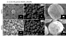
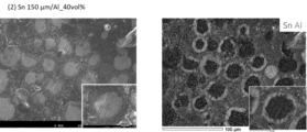
- Example 2 core raw material particles having an average particle size of 150 ⁇ m containing Sn as a component and child particles having an average particle size of 2 ⁇ m containing Al as a component were mixed at a ratio of 40 vol% (volume %). A photograph of the appearance of these raw material particles is shown in FIG. These raw material particles were put into a high-speed air impact device in the same manner as in Example 1, and subjected to a high-speed air impact impact method at a peripheral speed of 80 m/s and a treatment time of 3 minutes to form Sn core raw material particles. , Al child particle bombardment hybridization was performed to obtain the samples. In Example 2, no heat treatment was performed after hybridization.
- Example 2 (Repeated test (repeated durability test)) Using the sample of Example 2, the melting and solidification repetition test was conducted in the same manner as in Example 1 except that the number of repetitions was set to 50 times. Then, EDS analysis was performed on the appearance and cross section of the sample (latent heat storage particles) before and after the 50-times melting and solidification test. The results are shown in FIG.
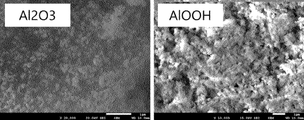
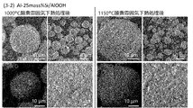
- Example 3 In Example 3, Al-25 mass% Si with an average particle size of 20 to 37 ⁇ m was used as core particles, and various Al compounds shown in Table 2 were used as child particles. Hybridization was performed in the same manner as in Example 1 under the conditions shown in Table 2 below to obtain samples. After hybridization, heat treatment was performed under the conditions shown in Table 2.
- FIG. 19 shows the photograph and EDS analysis results
- FIG. 20 shows the SEM micrograph of the appearance of the sample after heat treatment (the child particles are ⁇ -AlOOH) and the EDS analysis results
- FIG. 19 A SEM micrograph of the appearance and the results of EDS analysis are shown in FIG. FIG.
- FIG. 22 shows SEM micrographs and EDS analysis results of the cross section of each sample after heat treatment at 1000°C.
- the lower left photograph shows the EDS analysis results
- the dark gray indicates the detection of Al
- the dark gray indicates the detection of Al.
- grays close to white indicate the detection of Sn.
- the gray near black in the particle cross section indicates the detection of Si
- the light gray around it indicates the detection of Al
- the gray portion on the particle surface indicates the detection of Al and O.
- the coating portion containing Al is uniformly formed on the surface of the core particles with almost no gaps both before and after the heat treatment. Further, from the photographs in the lower part of FIG. 22, it can be seen that aggregates of particles derived from child particles are formed on the surface of the covering portion, and that at least part of the covering portion is in the form of particles.
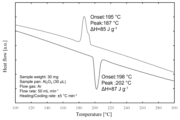
- the DSC measurement of the heat-treated latent heat storage particles was performed in the same manner as in Example 1. The results are shown in FIG. 25 for the sample heat-treated at 1000.degree. From this figure, it can be seen that all samples after heat treatment at high temperature maintain a high latent heat amount of 200 J/g or more, and are useful as a high-density heat storage material. Also, the sample heat-treated at 1150° C. is shown in FIG. From this figure, all the samples showed a high latent heat quantity of 150 J/g or more even after heat treatment at a higher temperature.
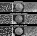
- Example 3-1 (SEM observation after repeated test) 100 times in the same manner as in Example 1 except that the latent heat storage particles of Example 3-1 using ⁇ -Al 2 O 3 as child particles are used and the atmosphere is an oxygen atmosphere with an oxygen concentration of 21%.
- a repeat test was performed. The appearance of the latent heat storage particles before and after the repeated test was observed by SEM (JEOL, JSM-7001FA), and EDS analysis was also performed. As a result, photographs before and after the repeated test are shown in FIG. In the EDS analysis results shown in the lower part of FIG. 27, the dark gray on the surface of each particle indicates the detection of Al, and the near-white gray observed on some particles indicates the detection of Sn. From FIG. 27, it was confirmed that even after repeated tests, there was almost no change in the appearance and components, the shape was maintained without leakage of PCM, and high durability was exhibited.
- Example 4 In Example 4, Zn-10 mass% Al having a particle diameter of 10 ⁇ m or more and a sieving size of less than 38 ⁇ m was used as core particles, and AlOOH was used as child particles at various volume ratios shown in Table 3. The total amount of core particles and child particles was 30 g.
- Hybridization was performed in the same manner as in Example 1 under the conditions shown in Table 3 below. A circumferential speed of 80 m/s in Table 3 corresponds to 13000 rpm.
- the atmosphere in the collision chamber of the high-velocity air impact device used for hybridization was an Ar atmosphere. After hybridization, heat treatment was performed under the conditions shown in Table 3 to obtain samples. The rate of temperature rise and cooling from room temperature to the heat treatment temperatures shown in Table 3 was 50°C/min.
- DSC measurement before and after repeated test The DSC measurement of the sample before and after the repeated test was performed in the same manner as in Example 1.
- the DSC measurement result (after heat treatment) of a sample with a child particle volume ratio of 20 vol% is shown in FIG. 31, and the DSC measurement result of a sample with a child particle volume ratio of 20 vol% (after 300 repeated tests) is shown in FIG.
- Figure 33 shows the DSC measurement result (after heat treatment) of a sample with a child particle volume ratio of 30 vol%
- Figure 34 shows the DSC measurement result (after heat treatment) of a sample with a child particle volume ratio of 40 vol%
- FIG. 35 shows the DSC measurement result (after 300 repeated tests) of the sample with 40 vol %.
- Example 5 In Example 5, as shown in Table 4, Al-26.5 mass% Cu-5.4 mass% Si having an average particle size of 25 to 38 ⁇ m was used as core particles, and ⁇ -Al 2 O 3 was used as child particles. . The total amount of core particles (15.37 g) and child particles (4.63 g) was 20 g. Hybridization was performed in the same manner as in Example 1 under the conditions shown in Table 4 below. The atmosphere in the collision chamber of the high-velocity air impact device used for hybridization was an Ar atmosphere. After hybridization, heat treatment was performed under the conditions shown in Table 4 to obtain samples. The temperature was raised from room temperature to the heat treatment temperature shown in Table 4 at a rate of 10°C/min.
- Example 5-1 (Repeated test (repeated durability test)) Using the sample of Example 5-1, a test was conducted in which melting and solidification were repeated 100 times. Specifically, after the sample is prepared, it is cooled from 1000° C. to 300° C. at 50° C./min in an air atmosphere, held at 300° C. for 10 minutes, and then returned to room temperature. After the temperature was raised to 650° C. and held at 650° C. for 2 minutes, the temperature was lowered to 300° C. and held for 2 minutes. Then, as the second time, the temperature is again raised from 300 ° C. to 650 ° C., held at 650 ° C. for 2 minutes, and then lowered to 300 ° C. and held for 2 minutes (both the temperature rise rate and the temperature drop rate are 50 ° C./min. ) was repeated a total of 100 times.
- the DSC measurement of the sample before and after the repeated test was performed in the same manner as in Example 1.
- the results are shown in FIG. FIG. 37 also shows the results of the sample after the heat treatment and not subjected to the repeated test and the result of the sample after the repeated test 100 times.
- the heat of fusion ⁇ H of the latent heat storage particles after the heat treatment was 291 J/g
- the heat of fusion ⁇ H of the latent heat storage particles after the repeated test was 300 J/g
- the heat of solidification ⁇ H of the latent heat storage particles after the heat treatment was 286 J/g
- the heat of solidification ⁇ H of the latent heat storage particles after the repeated test was 281 J/g.
- the sample encapsulating the Al alloy with a melting point of about 525°C exhibits the same surface properties and characteristics after the repeated test as before the repeated test.
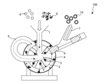
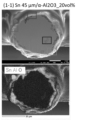
- Example 6 In Example 6, as shown in Table 5, Sn-9% by mass Zn having an undersize of less than 45 ⁇ m was used as core particles, and ⁇ -Al 2 O 3 was used as child particles. The total amount of core particles (26.46 g) and child particles (3.54 g) was 30 g. Hybridization was carried out in the same manner as in Example 1 under the conditions shown in Table 5 below to obtain samples.
- the atmosphere in the collision chamber of the high-velocity air impact device used for hybridization was an Ar atmosphere. In Example 6, no heat treatment was performed after hybridization.
- FIG. 39 shows the DSC measurement result of the raw material
- FIG. 40 shows the DSC measurement result of the sample after hybridization.
- sample after hybridization has the same characteristics as the raw material (core particle).
- microencapsulation of metal PCMs containing no Al or based on elements other than Al could be achieved. Furthermore, it has been possible to realize micro-order latent heat storage particles in which the covering portion is made of metal or ceramics other than Al 2 O 3 , which has not been realized so far. Furthermore, microencapsulation of Al alloy PCM could be performed more simply.
Abstract
Description
コア粒子と、該コア粒子の表面の少なくとも一部を被覆する被覆部とを有し、
前記コア粒子の成分は、Al、Mg、Si、Ti、Fe、Ni、Cu、Zn、Sn、Sb、Ga、In、Bi、Pb、およびCdよりなる群から選択される元素、または、これらを主成分とする合金または化合物であって、融点が100℃以上であり、
前記被覆部の成分は、前記コア粒子と作動温度の温度域で化学反応を生じない、前記コア粒子の成分と異なる、元素、該元素を含む合金および無機化合物、ならびにこれらの混合物よりなる群から選択される1以上であり、
前記被覆部の少なくとも一部は粒子形状である、潜熱蓄熱粒子である。
前記コア粒子の平均粒子径は、10μm以上、200μm以下である態様1に記載の潜熱蓄熱粒子である。
前記被覆部の少なくとも一部の粒子形状は、平均粒子径が0.1μm以上、2μm以下である、態様1または2に記載の潜熱蓄熱粒子である。
前記コア粒子の成分は、Al、Al-Si合金、Al-Cu-Si合金、Sn、Sn合金、およびZn-Al合金よりなる群から選択される1以上である、態様1~3のいずれかに記載の潜熱蓄熱粒子である。
前記被覆部の成分における無機化合物は、セラミックス、ガラス、および焼成によりα-Al2O3となるαアルミナ前駆体よりなる群から選択される1以上である、態様1~4のいずれかに記載の潜熱蓄熱粒子である。
前記被覆部の成分は、Al、α-Al2O3、AlOOH、Al(OH)3、およびガラスよりなる群から選択される1以上である、態様1~5のいずれかに記載の潜熱蓄熱粒子である。
前記被覆部に、前記コア粒子を構成する元素、該元素を含む合金および無機化合物、ならびにこれらの混合物よりなる群から選択される1以上が含まれる、態様1~6のいずれかに記載の潜熱蓄熱粒子である。
態様1~7のいずれかに記載の潜熱蓄熱粒子で形成された熱交換材料である。
成分がAl、Mg、Si、Ti、Fe、Ni、Cu、Zn、Sn、Sb、Ga、In、Bi、Pb、およびCdよりなる群から選択される元素、または、これらを主成分とする合金または化合物であって、融点が100℃以上であるコア原料粒子と、
成分が、前記コア粒子と作動温度の温度域で化学反応を生じない、前記コア粒子の成分(特には主成分)と異なる、元素、該元素を含む合金および無機化合物、ならびにこれらの混合物よりなる群から選択される1以上である子粒子とを準備すること、および、
前記コア原料粒子と前記子粒子を、高速気流中衝撃法で衝突させて、コア原料粒子の表面に子粒子を固着させるハイブリダイゼーションを行うこと
を含む、潜熱蓄熱粒子の製造方法である。
前記コア原料粒子の平均粒子径は、10μm以上、200μm以下であり、
前記子粒子の平均粒子径は、0.1μm以上、2μm以下であり、
(子粒子の平均粒子径/コア原料粒子の平均粒子径)の比率は、0.001以上、0.2以下である、態様9に記載の潜熱蓄熱粒子の製造方法である。
前記ハイブリダイゼーションは、40m/s以上、100m/s以下の周速度で行う、態様9または10に記載の潜熱蓄熱粒子の製造方法である。
前記ハイブリダイゼーションの後に、コア原料粒子の成分の融点以上の温度で熱処理を行う、態様9~11のいずれかに記載の潜熱蓄熱粒子の製造方法である。
〔コア粒子〕
コア粒子は、その成分が、Al、Mg、Si、Ti、Fe、Ni、Cu、Zn、Sn、Sb、Ga、In、Bi、Pb、およびCdよりなる群から選択される元素、または、これらを主成分とする合金または化合物であり、融点が100℃以上である。前記「主成分」とは、コア粒子全体に占める割合が50質量%以上であることをいう。前述のとおり、コア粒子を構成する成分は、潜熱蓄熱粒子の製造時において被覆部形成時に溶融しないことが必要であり、融点が100℃以上である必要がある。上記コア粒子は、固液相変化潜熱を利用できる相変化物質(PCM)であって、融解熱が、好ましくは例えば150J/g以上であり得、高い潜熱量を確保することができる。
被覆部の成分は、作動温度の温度域で、前記コア粒子と化学反応を生じない、前記コア粒子の成分と異なる、元素、該元素を含む合金および無機化合物、ならびにこれらの混合物よりなる群から選択される1以上で構成される。上記作動温度として、100℃以上、1500℃以下の範囲が挙げられる。前記元素として、Al、Mg、Si、Ti、Fe、Ni、Cu、Zn、Sn、Sb、Ga、In、Bi、Pb、およびCdよりなる群から選択される元素が挙げられる。前記無機化合物には、2以上の異なる無機化合物の混合物も含まれる。前記無機化合物として、セラミックス、ガラス、および焼成によりα-Al2O3となるαアルミナ前駆体よりなる群から選択される1以上が好ましい。前記セラミックスとして、α-Al2O3、θ-Al2O3等のアルミナ、SiO2(シリカ)などが挙げられる。また、前記αアルミナ前駆体は、例えば880℃以上の温度での焼成によってα-Al2O3となる化合物であり、該αアルミナ前駆体として、Al含有化合物、更にはAl含有酸化物および/またはAl含有水酸化物、更には、AlOOH、および/またはAl(OH)3が挙げられる。被覆部の成分は、より好ましくは、Al、α-Al2O3、AlOOH、Al(OH)3、およびガラスよりなる群から選択される1以上である。
本開示には、本実施形態に係る潜熱蓄熱粒子で形成された熱交換材料が含まれる。熱交換材料として、本実施形態に係る潜熱蓄熱粒子が熱交換材料の少なくとも一部を構成すればよく、例えば熱性母材中に分散して含有させる態様、多孔質材料中に分散して担持させる態様が挙げられる。熱交換材料の例としては、蓄熱レンガ、蓄熱用セラミックスボール、多孔質セラミックスフィルタ等が挙げられるがこれらに限定されない。
本実施形態に係る潜熱蓄熱粒子の製造方法は、所定の成分のコア原料粒子と、所定の成分の子粒子とを準備すること、および、前記コア原料粒子と前記子粒子を、高速気流中衝撃法で衝突させて、コア原料粒子の表面に子粒子を固着させるハイブリダイゼーションを行うことを含む。この製造方法によれば、従来の潜熱蓄熱粒子の製造方法と異なり、Alを含まない金属・合金PCMをコア原料粒子とする場合であっても、マイクロカプセル化を実現できる。また、様々な蓄熱温度のPCMをコア粒子とした潜熱蓄熱粒子を製造できる。更に、コア原料粒子の表面にアルミナ以外の材料を容易に被覆させることができ、被覆部がアルミナ以外の材料で形成された潜熱蓄熱粒子を容易に実現できる。以下では、各工程について説明する。
原料粒子として、コア原料粒子と、被覆部を形成するための子粒子を準備する。コア原料粒子は、所望の潜熱蓄熱粒子のコア粒子に対応させて、例えば平均粒子径が10μm以上、200μm以下の粒子を用意することが挙げられる。なお、コア原料粒子に、粒子径が10μm未満の微細な粒子が含まれていても、ハイブリダイゼーション時に、例えば微細な粒子どうしがぶつかり合うことで、例えば30μm程度の比較的大きな粒子が得られうる。上記平均粒子径は、例えば、更に100μm以下であってもよく、より更には50μm以下であってもよい。また子粒子の平均粒子径は、0.1μm以上、2μm以下であって、(子粒子の平均粒子径/コア原料粒子の平均粒子径)の比率は、0.001以上、0.2以下であることが好ましい。前記子粒子の平均粒子径は、更に1.0μm以下、より更には0.4μm以下であってもよい。コア原料粒子の成分は、潜熱蓄熱粒子のコア粒子の成分と同じであり、前記潜熱蓄熱粒子のコア粒子の成分について述べた通りである。また、子粒子の成分は、潜熱蓄熱粒子の被覆部の成分(特には主成分)と同じであり、前記潜熱蓄熱粒子の被覆部の成分で述べた通りである。なお、ハイブリダイゼーションの後に、コア原料粒子の成分の融点以上の温度で熱処理を行った場合、また実施例で行った繰り返し試験等の様に、融解凝固を繰り返し行った場合、潜熱蓄熱粒子の被覆部の成分は、子粒子の成分の酸化物であり得、また潜熱蓄熱粒子の被覆部の成分には、前述の通り、コア原料粒子の酸化物が含まれうる。
本実施形態では、コア原料粒子と被覆部を形成するための子粒子とを用い、乾式の機械的方法である高速気流中衝撃法で、コア原料粒子の表面に子粒子を機械的に打ち付け、コア原料粒子の表面に子粒子が固着した潜熱蓄熱粒子を得る。前記「固着」には、子粒子の形状変化等により物理的に接着することの他、コア原料粒子と子粒子との化学反応により接着することも含まれる。固着の程度は限定されず、コア粒子の表面の少なくとも一部が被覆されていればよい。コア粒子の表面に占める被覆部の被覆率は、高いほど好ましく、前述のとおり、50面積%以上であることが好ましく、より好ましくは70面積%以上、更に好ましくは80面積%以上、より更に好ましくは90面積%以上であり、最も好ましくは100面積%である。
熱処理条件は、コア原料粒子の成分と所望とする被覆部に応じて、温度と雰囲気を設定することができる。例えば、熱処理は、潜熱蓄熱材料の融点以上の温度で実行することが挙げられ、例えばコア原料粒子の成分の融点に応じて700℃以上に加熱することが挙げられる。この熱処理で、上記ハイブリダイゼーションにより形成された被覆部が酸化され、例えばより強固なアルミニウム酸化膜を形成することができる。熱処理により形成されるアルミニウム酸化膜は、概ね800℃以下の比較的低温ではγ-Al2O3の結晶形であり、化学的に安定とされるα-Al2O3膜は概ね880℃以上の比較的高温で得られる。化学的に安定なα-Al2O3膜を得るには、熱処理の温度を880℃以上とすることが好ましい。例えば880℃以上、1230℃以下とすることが好ましい。コア原料粒子が例えばAl-Si合金の場合、熱処理は900℃以上、1230℃以下の温度で行うことが挙げられる。一方、コア原料粒子が例えばSnの場合、例えば酸化雰囲気では約600℃で燃焼するため、600℃よりも低い温度で熱処理することが挙げられる。
実施例1では、成分がSnであって表1に示す平均粒子径のコア原料粒子と、成分がα-Al2O3であって平均粒子径が0.3μmの子粒子とを、コア原料粒子と子粒子の合計に対する子粒子の割合(体積比)が表1の通りとなるように用意した。そして、株式会社奈良機械製作所社製の高速気流中衝撃装置を用い、表1に示す条件で、高速気流中衝撃法により前記コア原料粒子と前記子粒子を衝突させる処理を行い、試料(潜熱蓄熱粒子)を得た。なお、実施例1-1と実施例1-2のどちらも、ハイブリダイゼーション後の熱処理は行わなかった。

実施例1-1の試料を用い、融解凝固を10回または100回繰り返す試験を行った。詳細には、大気(Air)雰囲気中で、400℃で1時間保持してから室温に戻し、その後、1回目として、400℃まで昇温し10分保持してから、40℃まで降温し10分間保持した。そして2回目として、再度、400℃まで昇温し10分保持してから、40℃まで降温し10分間保持する(昇温速度と降温速度はいずれも30℃/min)ことを、合計10回または合計100回繰り返した。そして100回繰り返し試験前後の試料のSEM観察とXRD測定、および10回繰り返し試験前後のDSC測定を、次の通り行った。
実施例1-1の試料の融解凝固100回繰り返し試験前の外観と断面、および100回繰り返し試験後の断面を、SEM(JEOL,JSM-7001FA)で観察した。その結果をそれぞれ図2、図3に示す。図2中央写真における濃いグレーのAlは、酸化アルミニウムを構成するAlを検出したものである。図2から明らかなとおり、試料(潜熱蓄熱粒子)の表面はほぼ酸化アルミニウム層で覆われていることを確認した。図2右下写真は、図2左下写真における破線囲み領域の拡大写真である。この図2右下写真に示される通り、被覆部の外縁部(最表層)には微粒子が堆積しており、被覆部の少なくとも一部が粒子形状であることがわかる。また、この堆積物にAlが含まれることを確認した。すなわち、ハイブリダイゼーションによって、コア粒子の表面に約500nm程度のAl2O3層(=シェル)形成されていることを確認した。また図3の下図において、中央の黒色部はSnの検出を示し、その周囲の白色に近いグレー部分はAlとOの検出を示す。この図3の下図から明らかなとおり、被覆部にはAlとOが検出された。このことから、融解凝固を100回繰り返す試験を行った後も、Al2O3で形成されたシェルが存在し、PCMの漏出を防止できていることがわかる。
融解凝固100回繰り返し試験前後の実施例1-1の試料を用い、以下の条件下で、XRD測定を行った。その結果を図4に示す。図4から、融解凝固100回繰り返し試験の前と後で結晶構造はほとんど変わらず、融解凝固100回繰り返し試験後も、該繰り返し試験前の結晶構造を維持できていることがわかる。
・X線回折装置:Rigaku MiniFlex600
・X線源:Cu線
・検出器:高速1次元検出器D/teX Ultra2
・管電圧:40kV
・管電流:15mA
・スキャンスピード:1.0°/min
・ステップ:0.01°
融解凝固10回繰り返し試験前と後の実施例1-1の試料を用い、示差走査熱量測定装置(METTLER TOLEDO社製、型番TGA/DSC3+)を使用し、アルミナパンを用いて、25~400℃の範囲において昇温速度10℃/分で、Ar雰囲気下にて示差走査熱量測定を行い、DSC曲線を得た。その結果を図5に示す。
実施例1-1の試料を用いて、Ar雰囲気下で、コア粒子を構成するSnの融点(232℃)よりも高い300℃または400℃まで10℃/minの昇温速度で昇温後自然冷却する熱耐久性試験を行った。そして熱耐久性試験後の試料の外観をSEMで観察した。それらの結果を図6に示す。
実施例2では、成分がSnである平均粒子径が150μmのコア原料粒子と、成分がAlである平均粒子径が2μmの子粒子とを、子粒子の全原料粒子に対する割合が40vol%(体積%)となる配合比率で準備した。これら原料粒子の外観写真を図15に示す。これらの原料粒子を、実施例1と同様に高速気流中衝撃装置に投入し、周速度:80m/s、処理時間:3分間の条件で、高速気流中衝撃法により、Snのコア原料粒子に、Alの子粒子を衝突させるハイブリダイゼーションを実施して、試料を得た。なお、実施例2において、ハイブリダイゼーション後の熱処理は行わなかった。
ハイブリダイゼーション後の試料(潜熱蓄熱粒子)の断面を、SEM(JEOL,JSM-7001FA)で観察し、かつEDS分析(エネルギー分散型X線分光分析)も行った。その結果を図16に示す。図16右のEDS分析結果において、各粒子の中央の黒に近いグレー部分はSnの検出を示し、その周囲を囲むシェル状の薄いグレー部分はAlの検出を示す。この図16から、実施例1においてAl2O3を子粒子として用いた場合と同様に、Alを子粒子とした場合にもカプセル化でき、マイクロオーダーの潜熱蓄熱粒子を作製できることがわかった。
実施例2の試料を用いて、繰り返し回数を50回とする以外は実施例1と同様にして融解凝固繰り返し試験を行った。そして融解凝固50回繰り返し試験前後の試料(潜熱蓄熱粒子)の外観と断面のEDS分析を行った。その結果を図17に示す。
実施例3では、平均粒子径が20-37μmのAl-25mass%Siをコア粒子に用い、子粒子として、表2に示す種々のAl化合物を用いた。下記表2の条件で、実施例1と同様にしてハイブリダイゼーションを行い、試料を得た。ハイブリダイゼーション後は、表2に示す条件で熱処理した。

熱処理前後の潜熱蓄熱粒子の外観を、SEM(JEOL,JSM-7001FA)で観察し、かつEDS分析も行った。その結果として、熱処理前の試料(子粒子が、α-Al2O3、AlOOH)のSEM顕微鏡写真を図18、熱処理後の試料(子粒子がα-Al2O3)の外観のSEM顕微鏡写真とEDS分析結果を図19、熱処理後の試料(子粒子がα-AlOOH)の外観のSEM顕微鏡写真とEDS分析結果を図20、熱処理後の試料(子粒子がAl(OH)3)の外観のSEM顕微鏡写真とEDS分析結果を図21に示す。また1000℃で熱処理後の各試料の断面のSEM顕微鏡写真とEDS分析結果を図22に示す。これらの図19~図21の各写真において、温度別に示された4つの写真のうち左下の写真はEDS分析結果を示しており、濃いグレーがAlの検出を示し、濃いグレーで覆われておらず、白色に近いグレーはSnの検出を示す。また図22の各中段の、EDS分析結果において、粒子断面の黒色に近いグレーはSiの検出、その周囲の薄いグレーはAlの検出を示し、粒子表面のグレー部分はAlとOの検出を示す。これらの写真から、熱処理前後のいずれにおいても、コア粒子の表面には、Alを含む被覆部がほとんど隙間なく均一に形成していることがわかる。また前記図22の各下段の写真から、被覆部の表面には、子粒子由来の粒子の集合体が形成され、被覆部の少なくとも一部は粒子形状であることがわかる。
熱処理後の潜熱蓄熱粒子のXRD測定を実施例1と同様にして行った。その結果を1000℃で熱処理した試料については図23、1150℃で熱処理した試料については図24に示す。これらの図から、高温で熱処理後のいずれの試料も、コア部はAl-Siで形成され、被覆部にはα-Al2O3が形成されていることがわかった。
熱処理後の潜熱蓄熱粒子のDSC測定を実施例1と同様にして行った。その結果を1000℃で熱処理した試料については図25に示す。この図から、高温で熱処理後のいずれの試料も200J/g以上の高い潜熱量を維持しており、高密度蓄熱体として有用であることがわかる。また、1150℃で熱処理した試料については図26に示す。この図から、より高温で熱処理後の場合でもあっても、いずれの試料も150J/g以上の高い潜熱量を示した。
子粒子としてα-Al2O3を用いた実施例3-1の潜熱蓄熱粒子を用い、雰囲気を酸素濃度21%の酸素雰囲気下で行うこと以外は、実施例1と同様にして100回の繰り返し試験を行った。そして繰り返し試験前後の潜熱蓄熱粒子の外観を、SEM(JEOL,JSM-7001FA)で観察し、かつEDS分析も行った。その結果として、繰り返し試験前後の写真を図27に示す。図27の下段に示すEDS分析結果において、各粒子表面の濃いグレーはAlの検出を示し、一部の粒子に観察される白に近いグレーはSnの検出を示す。この図27から、繰り返し試験を行っても、外観、成分ともに変化がほとんどなく、PCMの漏出がなく形状が維持され、高耐久性を示すことが確認された。
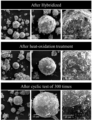
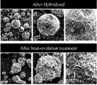
実施例4では、粒子径が10μm以上であって、篩下38μm未満のZn-10mass%Alをコア粒子に用い、子粒子としてAlOOHを、表3に示す種々の体積比で用いた。コア粒子と子粒子の合計量は30gであった。下記表3の条件で、実施例1と同様にしてハイブリダイゼーションを行った。表3における周速度80m/sは13000rpmに相当する。ハイブリダイゼーションに用いた高速気流中衝撃装置の衝突室の雰囲気は、Ar雰囲気とした。ハイブリダイゼーション後は、表3に示す条件で熱処理して、試料を得た。室温から表3に示す熱処理の温度までの昇温と冷却は50℃/minとした。

実施例4-1と4-3の試料を用い、融解凝固を300回繰り返す試験を行った。詳細には、大気(Air)雰囲気中で室温から250℃まで50℃/minで昇温し、250℃で10分保持してから、1回目として、250から500℃まで昇温し、500℃で2分間保持してから、250℃まで降温し2分間保持した。そして2回目として、再度、250から500℃まで昇温し、500℃で2分保持してから、250℃まで降温し2分間保持する(昇温速度と降温速度はいずれも50℃/min)ことを、合計300回繰り返した。
熱処理前後および繰り返し試験後の潜熱蓄熱粒子の外観を、走査型電子顕微鏡(SEM、日本電子株式会社製、品番:JSM-7001FA)で観察した。その結果として、子粒子の体積比が20vol%の試料のSEM顕微鏡写真を図28、子粒子の体積比が30vol%の試料のSEM顕微鏡写真を図29、子粒子の体積比が40vol%の試料のSEM顕微鏡写真を図30に示す。本実施例において、図面における「After Hybridixed」はハイブリダイゼーション後であって熱処理前の試料、「After heat-oxidation treatment」は熱処理後であって繰り返し試験を行っていない試料、「After cyclic test of 300 times」は繰り返し試験後の試料の結果を示す。以下同じである。
繰り返し試験前後の試料のDSC測定を実施例1と同様にして行った。その結果として、子粒子の体積比が20vol%の試料のDSC測定結果(熱処理後)を図31、子粒子の体積比が20vol%の試料のDSC測定結果(繰り返し試験300回後)を図32、子粒子の体積比が30vol%の試料のDSC測定結果(熱処理後)を図33、子粒子の体積比が40vol%の試料のDSC測定結果(熱処理後)を図34、子粒子の体積比が40vol%の試料のDSC測定結果(繰り返し試験300回後)を図35に示す。
実施例5では、表4に示す通り、平均粒子径が25~38μmのAl-26.5mass%Cu-5.4mass%Siをコア粒子に用い、子粒子としてα-Al2O3を用いた。コア粒子(15.37g)と子粒子(4.63g)の合計量は20gであった。下記表4の条件で、実施例1と同様にしてハイブリダイゼーションを行った。ハイブリダイゼーションに用いた高速気流中衝撃装置の衝突室の雰囲気は、Ar雰囲気とした。ハイブリダイゼーション後は、表4に示す条件で熱処理して、試料を得た。室温から表4に示す熱処理の温度までの昇温は10℃/minとした。

実施例5-1の試料を用い、融解凝固を100回繰り返す試験を行った。詳細には、試料作製後に大気(Air)雰囲気中で、1000℃から300℃まで50℃/minで冷却し、300で10分保持してから室温に戻し、その後、1回目として、300℃から650℃まで昇温し、650℃で2分間保持してから、300℃まで降温し2分間保持した。そして2回目として、再度、300℃から650℃まで昇温し、650℃で2分保持してから、300℃まで降温し2分間保持する(昇温速度と降温速度はいずれも50℃/min)ことを、合計100回繰り返した。
熱処理前後および繰り返し試験後の潜熱蓄熱粒子の外観を、SEM(JEOL,JSM-7001FA)で観察した。その結果を図36に示す。
繰り返し試験前後の試料のDSC測定を実施例1と同様にして行った。その結果を図37に示す。図37では、熱処理後であって繰り返し試験を行っていない試料と、100回繰り返し試験後の試料の結果をあわせて示す。図37において、熱処理後の潜熱蓄熱粒子の融解熱ΔHは291J/gであり、繰り返し試験後の潜熱蓄熱粒子の融解熱ΔHは300J/gであった。また、熱処理後の潜熱蓄熱粒子の凝固熱ΔHは286J/gであり、繰り返し試験後の潜熱蓄熱粒子の凝固熱ΔHは281J/gであった。
実施例6では、表5に示す通り、篩下45μm未満のSn-9質量%Znをコア粒子に用い、子粒子としてα-Al2O3を用いた。コア粒子(26.46g)と子粒子(3.54g)の合計量は30gであった。下記表5の条件で、実施例1と同様にしてハイブリダイゼーションを実施し、試料を得た。ハイブリダイゼーションに用いた高速気流中衝撃装置の衝突室の雰囲気は、Ar雰囲気とした。なお、実施例6において、ハイブリダイゼーション後の熱処理は行わなかった。

原料(コア粒子)およびハイブリダイゼーション後の試料の外観を、SEM(JEOL,JSM-7001FA)で観察した。その結果を図38に示す。図38において、上段の「Raw material」は原料(コア粒子)のSEM観察写真である。
原料(コア粒子)およびハイブリダイゼーション後の試料のDSC測定を実施例1と同様にして行った。その結果として、図39に原料のDSC測定結果、図40にハイブリダイゼーション後の試料のDSC測定結果を示す。
2 ローター
3 ブレード
4 ステーター
5 循環回路
6 排出弁
7 排出口
8 コア原料粒子
9 子粒子
10 潜熱蓄熱粒子
100 高速気流中衝撃装置
Claims (12)
- コア粒子と、該コア粒子の表面の少なくとも一部を被覆する被覆部とを有し、
前記コア粒子の成分は、Al、Mg、Si、Ti、Fe、Ni、Cu、Zn、Sn、Sb、Ga、In、Bi、Pb、およびCdよりなる群から選択される元素、または、これらを主成分とする合金または化合物であって、融点が100℃以上であり、
前記被覆部の成分は、前記コア粒子と作動温度の温度域で化学反応を生じない、前記コア粒子の成分と異なる、元素、該元素を含む合金および無機化合物、ならびにこれらの混合物よりなる群から選択される1以上であり、
前記被覆部の少なくとも一部は粒子形状である、潜熱蓄熱粒子。 - 前記コア粒子の平均粒子径は、10μm以上、200μm以下である請求項1に記載の潜熱蓄熱粒子。
- 前記被覆部の少なくとも一部の粒子形状は、平均粒子径が0.1μm以上、2μm以下である、請求項1または2に記載の潜熱蓄熱粒子。
- 前記コア粒子の成分は、Al、Al-Si合金、Al-Cu-Si合金、Sn、Sn合金、およびZn-Al合金よりなる群から選択される1以上である、請求項1~3のいずれかに記載の潜熱蓄熱粒子。
- 前記被覆部の成分における無機化合物は、セラミックス、ガラス、および焼成によりα-Al2O3となるαアルミナ前駆体よりなる群から選択される1以上である、請求項1~4のいずれかに記載の潜熱蓄熱粒子。
- 前記被覆部の成分は、Al、α-Al2O3、AlOOH、Al(OH)3、およびガラスよりなる群から選択される1以上である、請求項1~5のいずれかに記載の潜熱蓄熱粒子。
- 前記被覆部に、前記コア粒子を構成する元素、該元素を含む合金および無機化合物、ならびにこれらの混合物よりなる群から選択される1以上が含まれる、請求項1~6のいずれかに記載の潜熱蓄熱粒子。
- 請求項1~7のいずれかに記載の潜熱蓄熱粒子で形成された熱交換材料。
- 成分がAl、Mg、Si、Ti、Fe、Ni、Cu、Zn、Sn、Sb、Ga、In、Bi、Pb、およびCdよりなる群から選択される元素、または、これらを主成分とする合金または化合物であって、融点が100℃以上であるコア原料粒子と、
成分が、前記コア粒子と作動温度の温度域で化学反応を生じない、前記コア粒子の成分と異なる、元素、該元素を含む合金および無機化合物、ならびにこれらの混合物よりなる群から選択される1以上である子粒子とを準備すること、および、
前記コア原料粒子と前記子粒子を、高速気流中衝撃法で衝突させて、コア原料粒子の表面に子粒子を固着させるハイブリダイゼーションを行うこと
を含む、潜熱蓄熱粒子の製造方法。 - 前記コア原料粒子の平均粒子径は、10μm以上、200μm以下であり、
前記子粒子の平均粒子径は、0.1μm以上、2μm以下であり、
(子粒子の平均粒子径/コア原料粒子の平均粒子径)の比率は、0.001以上、0.2以下である、請求項9に記載の潜熱蓄熱粒子の製造方法。 - 前記ハイブリダイゼーションは、40m/s以上、100m/s以下の周速度で行う、請求項9または10に記載の潜熱蓄熱粒子の製造方法。
- 前記ハイブリダイゼーションの後に、コア原料粒子の成分の融点以上の温度で熱処理を行う、請求項9~11のいずれかに記載の潜熱蓄熱粒子の製造方法。
Priority Applications (2)
| Application Number | Priority Date | Filing Date | Title |
|---|---|---|---|
| CN202280059859.2A CN117916339A (zh) | 2021-09-07 | 2022-09-07 | 潜热蓄热粒子、热交换材料、和潜热蓄热粒子的制造方法 |
| KR1020247010626A KR20240051245A (ko) | 2021-09-07 | 2022-09-07 | 잠열 축열 입자, 열교환 재료, 및 잠열 축열 입자의 제조 방법 |
Applications Claiming Priority (2)
| Application Number | Priority Date | Filing Date | Title |
|---|---|---|---|
| JP2021145531 | 2021-09-07 | ||
| JP2021-145531 | 2021-09-07 |
Publications (1)
| Publication Number | Publication Date |
|---|---|
| WO2023038063A1 true WO2023038063A1 (ja) | 2023-03-16 |
Family
ID=85506381
Family Applications (1)
| Application Number | Title | Priority Date | Filing Date |
|---|---|---|---|
| PCT/JP2022/033596 WO2023038063A1 (ja) | 2021-09-07 | 2022-09-07 | 潜熱蓄熱粒子、熱交換材料、および潜熱蓄熱粒子の製造方法 |
Country Status (3)
| Country | Link |
|---|---|
| KR (1) | KR20240051245A (ja) |
| CN (1) | CN117916339A (ja) |
| WO (1) | WO2023038063A1 (ja) |
Citations (9)
| Publication number | Priority date | Publication date | Assignee | Title |
|---|---|---|---|---|
| JPH1123172A (ja) | 1997-06-30 | 1999-01-26 | Kedeika:Kk | 潜熱蓄熱カプセル |
| US20080272331A1 (en) * | 2006-08-21 | 2008-11-06 | Mohapatra Satish C | Hybrid nanoparticles |
| JP2012111825A (ja) | 2010-11-24 | 2012-06-14 | National Institute Of Advanced Industrial Science & Technology | 蓄熱体及び蓄熱方法 |
| JP2012140600A (ja) | 2010-12-13 | 2012-07-26 | Konica Minolta Business Technologies Inc | 蓄熱マイクロカプセルとその製造方法 |
| WO2015162929A1 (ja) * | 2014-04-24 | 2015-10-29 | 国立大学法人北海道大学 | 潜熱蓄熱体、潜熱蓄熱体の製造方法、および、熱交換材料 |
| WO2017200021A1 (ja) * | 2016-05-17 | 2017-11-23 | 国立大学法人北海道大学 | 潜熱蓄熱体マイクロカプセルおよび潜熱蓄熱体マイクロカプセルの製造方法 |
| JP2019203128A (ja) | 2018-05-21 | 2019-11-28 | Jx金属株式会社 | 潜熱蓄熱体、潜熱蓄熱体の製造方法、及び、熱交換材料 |
| WO2021039599A1 (ja) * | 2019-08-23 | 2021-03-04 | Jx金属株式会社 | 潜熱蓄熱材用マイクロカプセル及びその製造方法、並びに、潜熱蓄熱材用マイクロカプセルを含む粉末、及び当該粉末を含む蓄熱装置 |
| JP2021145531A (ja) | 2020-03-13 | 2021-09-24 | 日本精工株式会社 | モータコアの製造装置 |
-
2022
- 2022-09-07 WO PCT/JP2022/033596 patent/WO2023038063A1/ja active Application Filing
- 2022-09-07 CN CN202280059859.2A patent/CN117916339A/zh active Pending
- 2022-09-07 KR KR1020247010626A patent/KR20240051245A/ko unknown
Patent Citations (10)
| Publication number | Priority date | Publication date | Assignee | Title |
|---|---|---|---|---|
| JPH1123172A (ja) | 1997-06-30 | 1999-01-26 | Kedeika:Kk | 潜熱蓄熱カプセル |
| US20080272331A1 (en) * | 2006-08-21 | 2008-11-06 | Mohapatra Satish C | Hybrid nanoparticles |
| JP2012111825A (ja) | 2010-11-24 | 2012-06-14 | National Institute Of Advanced Industrial Science & Technology | 蓄熱体及び蓄熱方法 |
| JP2012140600A (ja) | 2010-12-13 | 2012-07-26 | Konica Minolta Business Technologies Inc | 蓄熱マイクロカプセルとその製造方法 |
| WO2015162929A1 (ja) * | 2014-04-24 | 2015-10-29 | 国立大学法人北海道大学 | 潜熱蓄熱体、潜熱蓄熱体の製造方法、および、熱交換材料 |
| JP2019173017A (ja) | 2014-04-24 | 2019-10-10 | 国立大学法人北海道大学 | 潜熱蓄熱体マイクロカプセル、潜熱蓄熱体の製造方法、熱交換材料、および触媒機能性潜熱蓄熱体 |
| WO2017200021A1 (ja) * | 2016-05-17 | 2017-11-23 | 国立大学法人北海道大学 | 潜熱蓄熱体マイクロカプセルおよび潜熱蓄熱体マイクロカプセルの製造方法 |
| JP2019203128A (ja) | 2018-05-21 | 2019-11-28 | Jx金属株式会社 | 潜熱蓄熱体、潜熱蓄熱体の製造方法、及び、熱交換材料 |
| WO2021039599A1 (ja) * | 2019-08-23 | 2021-03-04 | Jx金属株式会社 | 潜熱蓄熱材用マイクロカプセル及びその製造方法、並びに、潜熱蓄熱材用マイクロカプセルを含む粉末、及び当該粉末を含む蓄熱装置 |
| JP2021145531A (ja) | 2020-03-13 | 2021-09-24 | 日本精工株式会社 | モータコアの製造装置 |
Non-Patent Citations (1)
| Title |
|---|
| UCHIYAMA, TOMOYUKI; OTANI, MASARU; MINOSHIMA, HIRONORI; KAMOTA, SUICHI; MIYAKOSHI, YASUKI; SAKAI, MASAHIRO; ABE, YOSHIHIKO; AIYAMA: "Particulate Design by Dry Impact Blending Preparation Method (Part1). Preparation of Ni/Al2O3 Composite Particles", REPORTS OF HOKKAIDO RESEARCH ORGANIZATION INDUSTRIAL RESEARCH INSTITUTE, HOKKAIDO RESEARCH INSTITUTE, no. 292, 1 January 1993 (1993-01-01), pages 83 - 92, XP009544291, ISSN: 2189-1230 * |
Also Published As
| Publication number | Publication date |
|---|---|
| CN117916339A (zh) | 2024-04-19 |
| KR20240051245A (ko) | 2024-04-19 |
Similar Documents
| Publication | Publication Date | Title |
|---|---|---|
| JP6967790B2 (ja) | 潜熱蓄熱体マイクロカプセル、潜熱蓄熱体の製造方法、熱交換材料、および触媒機能性潜熱蓄熱体 | |
| US10490814B2 (en) | Method for the use of slurries in spray pyrolysis for the production of non-hollow, porous particles | |
| KR20210102427A (ko) | 리튬 이온 배터리용 리튬 전이 금속 산화물의 플라즈마 처리 | |
| JP2002504627A (ja) | 断熱材およびその製造方法 | |
| Wang et al. | Reaction products of Sm 2 Zr 2 O 7 with calcium-magnesium-aluminum-silicate (CMAS) and their evolution | |
| US20120201759A1 (en) | Tunable multiscale structures comprising bristly, hollow metal/metal oxide particles, methods of making and articles incorporating the structures | |
| JP7471663B2 (ja) | 潜熱蓄熱材用マイクロカプセル及びその製造方法、並びに、潜熱蓄熱材用マイクロカプセルを含む粉末、及び当該粉末を含む蓄熱装置 | |
| WO2019017467A1 (ja) | 銅粉、それを用いた光造形物の製造方法、および銅による光造形物 | |
| CN101830497A (zh) | 一种球形无机粉末颗粒的超重力水热制备方法 | |
| WO2003039790A2 (en) | Tightly agglomerated non-oxide particles and method for producing the same | |
| JP3825231B2 (ja) | 溶射用中空セラミックス粉末の製造方法 | |
| WO2023038063A1 (ja) | 潜熱蓄熱粒子、熱交換材料、および潜熱蓄熱粒子の製造方法 | |
| CN102892925A (zh) | 机械镀覆的丸粒和制造方法 | |
| Zhou et al. | Flexible core–shell structured Al-Cu alloy phase change materials for heat management | |
| Vasamsetti et al. | Synthesis, characterization and hardness studies of nano rice husk ash reinforced Al6061 nanocomposites | |
| JP2002226926A (ja) | 複合機能材料及びその製造方法 | |
| WO2022176746A1 (ja) | 潜熱蓄熱材用マイクロカプセル及びその製造方法、当該潜熱蓄熱材用マイクロカプセルを含む粉末、並びに、当該粉末を含む蓄熱装置 | |
| Kawaguchi et al. | Composite phase change material based on Al alloy with durability of over 10,000 cycles for high-temperature heat utilization | |
| JP2023038677A (ja) | 潜熱蓄熱粒子、熱交換材料、および潜熱蓄熱粒子の製造方法 | |
| JP4312286B2 (ja) | α−アルミン酸リチウムの製造方法 | |
| JP7352306B2 (ja) | 潜熱蓄熱体マイクロカプセルおよびその製造方法 | |
| CN108039467A (zh) | 海绵状硅粉及其制备方法及应用其的锂离子电池 | |
| JP2008520523A (ja) | アルミン酸アルカリ土類金属型の先駆化合物及び結晶化化合物並びに該結晶化化合物の製造方法及び該化合物の蛍光体としての使用方法 | |
| JP2023038675A (ja) | 潜熱蓄熱粒子、熱交換材料、および潜熱蓄熱粒子の製造方法 | |
| JP2022089069A (ja) | 溶射材料、それを用いた溶射方法、溶射皮膜 |
Legal Events
| Date | Code | Title | Description |
|---|---|---|---|
| 121 | Ep: the epo has been informed by wipo that ep was designated in this application |
Ref document number: 22867385 Country of ref document: EP Kind code of ref document: A1 |
|
| WWE | Wipo information: entry into national phase |
Ref document number: 2023546970 Country of ref document: JP |
|
| ENP | Entry into the national phase |
Ref document number: 20247010626 Country of ref document: KR Kind code of ref document: A |
|
| WWE | Wipo information: entry into national phase |
Ref document number: 2022867385 Country of ref document: EP |
|
| NENP | Non-entry into the national phase |
Ref country code: DE |
|
| ENP | Entry into the national phase |
Ref document number: 2022867385 Country of ref document: EP Effective date: 20240408 |