WO2023038019A1 - 融着機、光ファイバの接続方法 - Google Patents
融着機、光ファイバの接続方法 Download PDFInfo
- Publication number
- WO2023038019A1 WO2023038019A1 PCT/JP2022/033367 JP2022033367W WO2023038019A1 WO 2023038019 A1 WO2023038019 A1 WO 2023038019A1 JP 2022033367 W JP2022033367 W JP 2022033367W WO 2023038019 A1 WO2023038019 A1 WO 2023038019A1
- Authority
- WO
- WIPO (PCT)
- Prior art keywords
- optical fiber
- fusion splicer
- waveguide member
- optical waveguide
- adjustment mechanism
- Prior art date
Links
- 239000013307 optical fiber Substances 0.000 title claims abstract description 199
- 230000004927 fusion Effects 0.000 title claims abstract description 41
- 238000000034 method Methods 0.000 title claims description 9
- 230000007246 mechanism Effects 0.000 claims abstract description 96
- 230000003287 optical effect Effects 0.000 claims description 54
- 239000000835 fiber Substances 0.000 claims description 14
- 238000010586 diagram Methods 0.000 description 23
- 238000003384 imaging method Methods 0.000 description 19
- 238000009434 installation Methods 0.000 description 9
- 230000033001 locomotion Effects 0.000 description 7
- 238000007796 conventional method Methods 0.000 description 4
- 230000007423 decrease Effects 0.000 description 3
- 241000238631 Hexapoda Species 0.000 description 2
- 238000012986 modification Methods 0.000 description 2
- 230000004048 modification Effects 0.000 description 2
- 125000006850 spacer group Chemical group 0.000 description 2
- 238000005452 bending Methods 0.000 description 1
- 230000005540 biological transmission Effects 0.000 description 1
- 230000008602 contraction Effects 0.000 description 1
- 230000008878 coupling Effects 0.000 description 1
- 238000010168 coupling process Methods 0.000 description 1
- 238000005859 coupling reaction Methods 0.000 description 1
- 238000007599 discharging Methods 0.000 description 1
- 230000000694 effects Effects 0.000 description 1
- 238000007526 fusion splicing Methods 0.000 description 1
- 238000010191 image analysis Methods 0.000 description 1
Images


Classifications
-
- G—PHYSICS
- G02—OPTICS
- G02B—OPTICAL ELEMENTS, SYSTEMS OR APPARATUS
- G02B6/00—Light guides; Structural details of arrangements comprising light guides and other optical elements, e.g. couplings
- G02B6/24—Coupling light guides
- G02B6/255—Splicing of light guides, e.g. by fusion or bonding
-
- G—PHYSICS
- G02—OPTICS
- G02B—OPTICAL ELEMENTS, SYSTEMS OR APPARATUS
- G02B6/00—Light guides; Structural details of arrangements comprising light guides and other optical elements, e.g. couplings
- G02B6/24—Coupling light guides
- G02B6/26—Optical coupling means
Definitions
- the present invention relates to a fusion splicer and the like for fusion splicing optical fibers.
- a fusion splicer is used to connect optical fibers.
- the fusion splicer connects optical fibers held by a pair of holders to each other by arranging them between electrodes and by fusing the ends of the optical fibers with an arc.
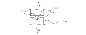
- FIG. 14A is a front view showing a state in which the optical fiber 103 is arranged in the guide portion 100
- FIG. 14B is a cross-sectional view taken along line XX of FIG. 14A.
- the optical fiber 103 is arranged in the V-groove 101 of the guide portion 100, is held by the guide portion 100 by being pressed from above by a clamp 105, and faces another optical fiber (not shown). do.
- the optical fibers are aligned by the holder 107 holding the optical fibers 103 and the guide section 100 so that the axial centers Y of the opposing optical fibers 103 are aligned with each other.
- the optical fibers 103 facing each other are butted against each other, arranged between a pair of electrodes, and an electric discharge is generated between the electrodes, whereby the optical fibers 103 can be fusion-spliced.
- the axial center of the holder 107 and the axial center of the guide portion 100 may deviate from each other due to the positional accuracy of each part and the bending tendency of the optical fiber 103 .
- the clamp 105 presses the optical fiber 103 along the V-groove 101, and the axial center of the optical fiber 103 is V-shaped on the side facing the other optical fibers. It can be substantially the same as the axis of the groove 101 .
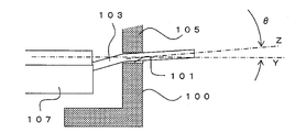
- the rigidity of the optical fiber 103 is stronger than the pressing force of the clamp 105, as shown in FIG. , is shifted by an angle ⁇ in the height direction. That is, the axial center of the optical fiber 103 and the facing direction of the optical fiber 103 do not match.
- FIG. 15A is a plan view showing a state in which the optical fiber 103 is arranged in the guide section 100.
- FIG. As described above, it is desirable that the axis Y of the V-groove 101 in the holder 107 and the guide portion 100 match, but as shown in FIG. be. Also in this case, the axial center Z of the optical fiber 103 is shifted horizontally by an angle ⁇ with respect to the facing direction (Y in the figure) of the optical fibers 103 .
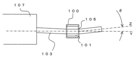
- FIG. 16 is a conceptual diagram showing a state in which the tapered optical fiber 103a is arranged in the V-groove 101 of the guide portion 100. As shown in FIG.
- the tip position of the optical fiber 103a can be aligned by a conventional method, but the axial center Z of the optical fiber 103a is , with respect to the facing direction of the optical fibers 103a by an angle ⁇ .
- the tip positions of the optical fibers facing each other can be aligned, loss increases unless the axial centers of the optical fibers are arranged on a straight line.
- the present invention has been made in view of such problems, and an object of the present invention is to provide a fusion splicer or the like capable of accurately connecting optical waveguide members.
- a first invention is a fusion splicer capable of connecting an optical waveguide member and an optical fiber, comprising a pair of guide portions for positioning the optical waveguide member and the optical fiber so as to face each other. and a pair of electrodes arranged to face each other in a direction substantially perpendicular to the facing direction of the pair of guide portions, wherein at least one of the guide portions is inclined in a direction to cancel the inclination of the optical waveguide member.
- the fusion splicer is characterized in that it is possible to hold the optical waveguide member in a state of being held.
- At least one of the guide portions may have an inclination angle adjustment mechanism capable of adjusting an inclination angle with respect to the opposing direction.
- a control unit may be provided that acquires tilt angle information of the optical waveguide member from the image of the optical waveguide member and controls the tilt angle adjustment mechanism.
- the tilt angle adjustment mechanism may be capable of adjusting at least the tilt angle with respect to the facing direction when viewed from the axial direction of the electrodes.
- the tilt angle adjustment mechanism may be capable of adjusting at least the tilt angle with respect to the facing direction in plan view.
- the tilt angle adjustment mechanism may be capable of independently adjusting the tilt angle with respect to the facing direction when viewed from the axial direction of the electrode and the tilt angle with respect to the facing direction in plan view.
- the tilt angle adjusting mechanism may be capable of adjusting the tilt angle by rotating the guide section to move it in an arc.
- a position adjustment mechanism for aligning the tip position of the optical waveguide member or the optical fiber may be provided, and the position adjustment mechanism and the tilt angle adjustment mechanism may be independently controllable.
- the position adjustment mechanism is arranged on one of the guide portions, and the tilt angle adjustment mechanism is arranged on the other guide portion.
- the tilt angle adjusting mechanism may be arranged on each of the pair of guide portions.
- the optical waveguide member may be an optical fiber having a tapered shape in which the diameter becomes smaller toward the tip.
- the optical waveguide member may be held in a state in which the guide portion is inclined at an angle larger than the taper angle of the optical waveguide member with respect to the facing direction.
- the inclination of the guide portion is 3 degrees or less with respect to the facing direction.
- the guide portion can hold the optical waveguide member in a state inclined in a direction that cancels the inclination of the optical waveguide member, even if the axial direction of the optical waveguide member is inclined, , the axial direction of the optical waveguide member can be aligned with the facing direction of the optical fibers. Therefore, the axial centers of the optical waveguide member and the optical fiber facing each other can be arranged on a straight line.
- the guide portion can be adjusted to an appropriate tilt angle according to the optical waveguide member.
- the tilt angle adjusting mechanism can adjust the tilt angle with respect to the facing direction when viewed from the axial direction of the electrodes, it is possible to adjust the tilt angle when the axes of the holder and the guide section are misaligned in the height direction, Even when the optical waveguide member has a tapered shape, the axial direction can be aligned with the opposing direction.
- the tilt angle adjustment mechanism if at least the tilt angle with respect to the facing direction in plan view can be adjusted, even when the horizontal axis of the holder and the guide part is misaligned, the axial direction can be adjusted to the facing direction. can be matched.
- the tilt angle adjustment mechanism can adjust the tilt angle by rotating the guide portion in an arc shape, it is possible to adjust the angle even for minute tilts in a stepless manner.
- the mechanism in each guide portion can be made smaller.
- the optical waveguide member can also be applied to an optical fiber having a tapered shape in which the diameter becomes smaller toward the tip. It can also be applied when held in a state of being tilted at a large angle. At this time, the inclination of the guide portion with respect to the opposing direction of the guide portion can be 3 degrees or less.
- a second invention is a method for connecting an optical waveguide member and an optical fiber using the fusion splicer according to the first invention, wherein the optical waveguide member is arranged in at least one guide portion, and the optical waveguide member and the optical fiber are opposed to each other, the abutting portion is arranged between the electrodes, and the optical waveguide member and the optical fiber are fused by electric discharge.
- the optical waveguide member may be a bundle fiber in which a plurality of optical fiber core wires are bundled and has a tapered shape in which the diameter becomes narrower toward the tip.
- the optical waveguide member and the optical fiber can be fusion-spliced with high precision by aligning their axial centers.
- optical waveguide member is a bundled optical fiber, it can be fusion-spliced in the same manner as a single-core optical fiber.
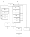
- FIG. 2 is a perspective view showing the fusion splicer 1; 4 is a configuration diagram showing a control mechanism for the operation of the guide section 5 of the fusion splicer 1.
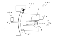
- FIG. FIG. 4 is an enlarged schematic view of the vicinity of the guide portion 5;
- FIG. 4 is an enlarged schematic view of the vicinity of the guide portion 5;
- FIG. 25 is a conceptual diagram of an image 25;
- FIG. 2 is a conceptual front view of a state in which an optical fiber 23 is arranged in a guide portion 5;
- FIG. 2 is a conceptual side view of a state in which an optical fiber 23 is arranged in a guide portion 5;
- FIG. 4 is a conceptual diagram of a method for measuring the tilt of the optical fiber 23;
- FIG. 10 is a diagram showing another tilt adjustment method of the optical fiber 23;
- FIG. 4 is a configuration diagram showing another control mechanism for the operation of the guide section 5 of the fusion splicer 1; The side view which shows the bundle fiber 23a.
- FIG. 9A is a cross-sectional view taken along line LL of FIG. 9A. MM line sectional view of FIG. 9A.
- FIG. 4 is a conceptual diagram showing a fused state of the end cap 29; 4 is a conceptual diagram showing an inclination angle adjusting mechanism 19 of the guide portion 5.
- FIG. 4 is a conceptual diagram showing an inclination angle adjusting mechanism 19 of the guide portion 5.
- FIG. 4 is a conceptual diagram showing an inclination angle adjusting mechanism 19 of the guide portion 5.
- FIG. 4 is a conceptual diagram showing an inclination angle adjusting mechanism 19 of the guide portion 5.
- FIG. 4 is a conceptual diagram showing an inclination angle adjusting mechanism 19 of the guide portion 5.
- FIG. 4 is a conceptual diagram showing an
- FIG. 4 is a configuration diagram showing another operation control mechanism of the guide section 5 of the fusion splicer 1.
- FIG. 4 is a conceptual diagram showing an inclination angle adjusting mechanism 19a of the guide portion 5.
- FIG. 4 is a conceptual diagram showing an inclination angle adjusting mechanism 19a of the guide portion 5.
- FIG. 4 is a front view showing a state in which the optical fiber 103 is installed in the guide section 100 by a conventional method; XX line sectional view of FIG. 14A.
- FIG. 4 is a conceptual diagram showing a case in which a conventional holder 107 and a guide portion 100 are misaligned from each other in the height direction.
- FIG. 4 is a plan view showing a state in which the optical fiber 103 is installed in the guide section 100 by a conventional method;
- FIG. 4 is a conceptual diagram showing a case where a conventional holder 107 and a guide part 100 are misaligned in the horizontal direction.
- FIG. 2 is a conceptual diagram showing a state in which a tapered optical fiber 103a is installed in a conventional guide section 100;
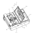
- FIG. 1 is a perspective view showing the fusion splicer 1
- FIG. 2 is a configuration diagram showing a mechanism for controlling the operation of the guide section 5 of the fusion splicer 1.
- FIG. 1 is a perspective view showing the fusion splicer 1
- FIG. 2 is a configuration diagram showing a mechanism for controlling the operation of the guide section 5 of the fusion splicer 1.
- FIG. 1 is a perspective view showing the fusion splicer 1
- FIG. 2 is a configuration diagram showing a mechanism for controlling the operation of the guide section 5 of the fusion splicer 1.
- FIG. 1 connection of an optical waveguide member having a tapered shape in which the diameter becomes smaller toward the tip will be described.
- the optical waveguide member refers to a member including an optical fiber and having a function of guiding light.
- an optical fiber is used as the optical waveguide member. That is, an example of connecting a pair of optical fibers having a tapered shape will be described as the connection of an optical waveguide
- the fusion splicer 1 includes a holder mounting portion 11 on which a holder for holding an optical fiber is mounted, a pair of guide portions 5 for positioning the pair of optical fibers so as to face each other, and a direction in which the pair of optical fibers face each other ( A pair of electrodes 7 facing each other in a direction substantially perpendicular to the facing direction of the pair of guide portions 5, a lid portion 3, an operation portion 15 for operating the fusion splicer 1, and various information are displayed.
- a display unit 17 and the like are provided. Note that the operation unit 15 and the display unit 17 may be integrated by using a touch panel as the display unit 17 .
- the optical fiber is held in the V groove on the guide portion 5.
- the lid portion 3 is rotatable around the rotating shaft 9 .
- a clamp 13 is provided on the rear surface of the lid portion 3 , and when the lid portion 3 is closed, the tip of the clamp 13 is positioned at a position corresponding to the position of the optical fiber on the guide portion 5 . That is, a pair of optical fibers can be held facing each other at the respective guide portions 5 by a pair of clamps 13 provided on the back surface of the lid portion 3 .
- the clamp 13 may be arranged independently of the lid portion 3 without being provided on the lid portion 3 .
- the pair of guide portions 5 are provided with a tilt drive portion 31, a rotation drive portion 32, and a transport drive portion 33, and at least one of the guide portions 5 further has a tip position of the optical fiber.
- An X-direction drive 34 and a Y-direction drive 35 are provided for alignment. Note that the X-direction driving section 34 and the Y-direction driving section 35 may be arranged on both guide sections 5 .
- the rotation driving unit 32 is required, but the rotational alignment is unnecessary. In that case, the rotation drive section 32 is not necessarily required.
- the fusion splicer 1 connects a pair of optical fibers by fusion.
- An optical fiber is held by a pair of holders (not shown), and the holders are placed on the holder placement section 11 .
- the lid portion 3 By closing the lid portion 3 in this state, the optical fiber is held in the guide portion 5 .
- the tips of the pair of optical fibers held by the guide section 5 are transported between the pair of electrodes 7 by the transport driving section 33 .
- An X-direction imaging unit 36 and a Y-direction imaging unit 37 are arranged below the electrodes 7 .
- the X-direction imaging section 36 and the Y-direction imaging section 37 can capture images from the sides near the tip of the optical fiber from different directions.
- the X-direction imaging section 36 and the Y-direction imaging section 37 can image the position of the tip of the optical fiber.
- Information obtained by each imaging unit can be processed by the image processing unit 38 and displayed on the display unit 17 . Further, the obtained image information is processed by the arithmetic processing section 39 and the operation of the guide section 5 is controlled by the control section 30 .
- the optical fibers are aligned by automatically or manually moving the guide unit 5 in each direction so that the tip positions of the optical fibers are aligned, and the tips of the optical fibers are faced to face each other.
- a butt is positioned between the electrodes.
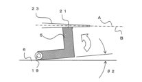
- 3A is a conceptual diagram showing a state in which the tapered optical fiber 23 is arranged in the V groove 21 of the guide portion 5.
- FIG. It should be noted that illustration of the clamp 13 and the holder is omitted in the following description.
- the axis of the optical fiber 23 (B in the figure) is positioned at a predetermined angle ( ⁇ 1 in the figure) with respect to the opposing direction (A in the figure) of the opposing optical fibers. deviate.
- a pair of guide portions 5 are arranged on the guide portion installation portion 6, respectively, and each of the guide portions 5 is adjusted by the tilt angle adjustment mechanism 19 (tilt driving portion 31 (see FIG. 2)). The inclination angle with respect to the installation portion 6 can be adjusted.
- a hinge-like structure is shown as the tilt angle adjustment mechanism 19 for the sake of simplicity, but the tilt angle adjustment mechanism 19 is not particularly limited, and a gonio stage or the like that rotates in an arc without changing its position can be used. It is possible to apply a mechanism that can only perform Details of the tilt angle adjusting mechanism 19 will be described later.
- FIG. 3B is a diagram showing a state in which the tilt angle adjustment mechanism 19 is operated and the guide portion 5 is tilted by an angle ⁇ 2 with respect to the guide portion setting portion 6.
- FIG. 3B is a diagram showing a state in which the tilt angle adjustment mechanism 19 is operated and the guide portion 5 is tilted by an angle ⁇ 2 with respect to the guide portion setting portion 6.
- the tilt angle adjustment mechanism 19 rotates in a horizontal direction (perpendicular to the paper surface) substantially perpendicular to each of the installation direction of the optical fiber 23 (vertical direction in the drawing) and the facing direction of the optical fiber 23 (horizontal direction in the drawing).
- the guide part 5 can be rotated by the shaft.
- a conventional method can be applied to the moving mechanism in the X direction and the moving mechanism in the Y direction. That is, the moving mechanism in the X direction and the moving mechanism in the Y direction can move the guide portion 5 in parallel in each direction. At this time, it is desirable that the tilt angle adjustment mechanism 19 can adjust the tilt angle of the guide portion 5 independently of the movement mechanism in the X direction and the movement mechanism in the Y direction. That is, in the case of having a position adjustment mechanism for aligning the tip position of the optical fiber, it is desirable that the position adjustment mechanism (parallel movement mechanism) and the tilt angle adjustment mechanism can be controlled independently.
- the movement and rotation in each direction may be simultaneously controlled by expanding and contracting each cylinder, and the tip position and tilt angle of the optical fiber may be adjusted at the same time.
- the position adjustment and the tilt angle adjustment may be controlled completely independently, compared to the case of simultaneously controlling the movement and rotation in each direction by controlling the expansion and contraction of each cylinder like a hexapod. Even if an error occurs in the position adjustment, this error can be finely corrected only by the position adjustment mechanism, and in this case, the influence on the tilt angle can be reduced, which is preferable.
- the tapered optical fiber 23 is arranged in the V-groove 21 of the guide portion 5 .
- One of the optical fibers may be a normal optical fiber with the same diameter. That is, the tapered optical fiber 23 is arranged in at least one of the guide portions 5 . In this manner, the tapered optical fibers 23 can be connected to each other, or the tapered optical fiber 23 and a normal optical fiber can be connected.
- FIG. 4 is a conceptual diagram showing an image 25 captured by the X-direction imaging unit 36 or the Y-direction imaging unit 37, for example.
- the imaging unit can image the tip of the optical fiber 23 .
- the image processing unit 38 and the arithmetic processing unit 39 can acquire the tapered angles ⁇ 3 and ⁇ 4 near the tip of each optical fiber 23 captured by image analysis.
- the image processing unit 38 can binarize the image, detect the boundary line of the outer shape of the optical fiber 23, and the arithmetic processing unit 39 can calculate the angle of the obtained straight line.
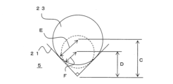
- FIG. 5A is a conceptual front view of a state in which the optical fiber 23 is arranged in the guide portion 5
- FIG. 5(b) is a conceptual side view.
- half of ⁇ 3 in FIG. 4 is assumed to be ⁇ 5 in FIG. 5B.
- the depth of the optical fiber 23, which gradually decreases toward the tip, is arranged in the V-groove 21 depending on the position.
- the inclination angle of the axis when the optical fiber 23 is arranged in the V-groove 21 of the guide portion 5 can be calculated.
- the image of the tip of the optical fiber 23 is acquired by the imaging unit, the taper angle information of the optical fiber 23 is acquired by the image processing unit 38 and the arithmetic processing unit 39, and the optical fiber 23 is obtained from the taper angle information. 23 can be calculated.
- the control unit 30 can control the tilt angle adjustment mechanism 19 (tilt driving unit 31) to tilt the guide unit 5 in the opposite direction so as to cancel the tilt angle of the axis of the optical fiber 23.
- FIG. At this time, by making the inclination angle of the V-groove 21 (guide portion 5) holding the optical fiber 23 larger than the taper angle ⁇ 5 of the optical fiber 23, the axial direction of the optical fiber 23 is set in the opposite direction. , or the angle difference with the opposing direction can be reduced. In this way, it is possible to fuse the tapered optical fiber with a simple structure with high precision and with reduced splicing loss.
- the adjustment of the tilt angle of the guide section 5 may be performed manually by operating the operation section 15 while viewing the image on the display section 17 instead of the automatic adjustment by the control section 30 . Further, instead of obtaining the taper angle of the optical fiber 23 based on the image and calculating the inclination angle of the axis of the optical fiber 23 from the taper angle, the inclination angle of the axis may be calculated directly from the image.
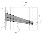
- FIG. 6 is a conceptual diagram of an image 25a captured by the imaging unit.
- the image 25a is an image captured from the side of the optical fiber 23, for example. That is, the image 25a is obtained such that the vertical direction of the image 25a coincides with the vertical direction of the guide portion 5 (the vertical direction in FIG. 3A). Although only the tip of one optical fiber is shown, the same applies to the other optical fiber.
- the optical fiber 23 is arranged at predetermined intervals in the facing direction of the optical fiber 23 (the direction of the straight line J in the figure).
- the positions of the upper boundary (G in the figure) and the lower boundary (H in the figure) are detected, and the midpoint (I in the figure) is recognized as the center position of the optical fiber 23 .
- the arithmetic processing unit 39 can connect this center position to the facing direction of the optical fiber 23 to calculate the axial direction of the optical fiber 23 (the direction of the straight line K in the figure). That is, it is possible to calculate the inclination angle between the facing direction of the optical fiber 23 (straight line J in the drawing) and the axial direction of the optical fiber 23 (straight line K in the drawing).
- the tilt angle of the axis may be calculated based on the image of the optical fiber 23 captured by at least one of the X-direction imaging section 36 and the Y-direction imaging section 37 .
- the inclination angle adjustment mechanism 19 can adjust the inclination angle of the guide portion 5 according to the taper angle of the optical fiber 23 . If the taper angle of the optical fiber 23 is known in advance, the angle of the guide portion 5 may be slanted in advance according to that angle. In this case, as shown in FIG. 7, a spacer 27 may be sandwiched under the guide portion 5 to change the angle of the guide portion 5 .
- the taper angle when the taper angle is known in advance, it is possible to hold the optical fiber 23 in a state in which at least one of the guide portions 5 is tilted in a direction that cancels the tilt due to the tapered shape of the optical fiber 23.
- the tilt angle adjustment mechanism may not be used.
- at least one of the guide portions 5 has an inclination angle adjustment mechanism 19 capable of adjusting the inclination angle.
- the tilt angle adjustment mechanism 19 tilt drive section 31
- the tilt angle adjustment mechanism 19 tilt drive section 31
- one guide portion 5 is provided with a position adjustment mechanism (X-direction drive portion 34, Y-direction drive portion 35), and the other guide portion 5 is provided with a tilt angle adjustment mechanism (tilt drive portion 31). ) may be placed.
- a position adjustment mechanism X-direction drive portion 34, Y-direction drive portion 35
- a tilt angle adjustment mechanism tilt drive portion 31
- the inclination angle adjustment mechanism 19 is arranged only in one of the guide portions 5, when the tapered optical fibers 23 are arranged in the respective guide portions 5, the one guide portion 5 is connected to the respective optical fibers. 23 can be tilted by the sum of the tilt angles.
- the adjustable range of the tilt angle by the tilt angle adjustment mechanism 19 is restricted to a predetermined value or less.
- a predetermined value or less For example, in the range of about 15 mm, which is the distance from the holder to the electrode 7, if the optical fiber with the largest outer diameter of 800 ⁇ m has a tapered shape in which the tip is 0 ⁇ m (i.e., isosceles triangle), The taper angle in this case is approximately 3 degrees. That is, assuming that the taper angle of the optical fiber is 3 degrees at maximum, it is possible to correspond to almost all optical fibers.
- the tilt angle adjustment range of the guide portion 5 is desirably 3 degrees or less at maximum, and more desirably 1.5 degrees or less.
- the tapered optical fiber 23 can be fusion-spliced with the axial center aligned on a straight line. Therefore, an increase in transmission loss can be suppressed.
- the tilt angle of the guide unit 5 is adjusted to an appropriate tilt angle according to the taper angle of each optical fiber 23. It is possible.
- the guide portion 5 is automatically adjusted to an appropriate angle by setting the optical fiber 23 and closing the lid portion 3. can be adjusted.
- At least one of the guide portions 5 has an inclination angle adjustment mechanism 19 capable of adjusting the inclination angle, it is possible to connect the tapered optical fibers 23 to each other. By providing the adjustment mechanism 19, the inclination angle of each guide portion 5 can be reduced.
- the tapered optical waveguide member to be fused may be not only a single optical fiber but also a bundle fiber in which a plurality of optical fibers are bundled.
- 9A is a side view of a bundle fiber 23a in which a plurality of tapered optical fibers 23 are bundled
- FIG. 9B is a cross-sectional view taken along line LL of FIG. 9A
- FIG. 9C is a cross-sectional view taken along line MM of FIG. 9A. It is a line sectional view.
- the bundle fiber 23a is an optical fiber in which a plurality of optical fibers 23 are bundled and integrated by adhesion or the like.
- the overall outer diameter (diameter of the circumscribed circle) of the bundle fiber 23a also tapers toward the tip.
- the number of optical fibers 23 forming the bundle fiber 23a is not limited to the illustrated example. Further, the optical fibers 23 forming the bundle fiber 23a may not all have the same diameter, and may not all be tapered fibers.
- the optical fiber to be fusion-spliced by the fusion splicer 1 may be a single optical fiber 23 having a tapered shape, or a bundle fiber in which a plurality of optical fibers 23 are bundled.
- FIG. 10 is a conceptual diagram when the end cap 29 as an optical waveguide member is fused to the end of the optical fiber 23b.
- the end cap 29 is connected to the input end of the optical fiber or the like, and when the laser light is coupled to the optical fiber, the heat effect and damage to the input end of the optical fiber can be reduced by coupling through the end cap. It becomes possible.
- the end cap 29 has a tapered shape on the side connected to the optical fiber.
- the guide portion 5 is inclined so as to correspond to the tapered shape of a part of the end cap 29, and the ends of the optical fiber 23b and the end cap 29 are aligned with each other.
- the optical fiber 23b to be connected may have substantially the same diameter up to the tip, or may have a tapered shape.
- the guide portion 5 holding the optical fiber 23b may also be inclined corresponding to the tapered shape.
- At least one of the optical waveguide members has a tapered shape in which the outer diameter decreases toward the tip.
- FIG. can also be applied to adjust axial misalignment of the optical fiber due to axial misalignment in the height direction.
- FIG. 11A is a schematic diagram showing the tilt angle adjusting mechanism 19 as seen from the axial direction of the electrode.
- the guide section 5 is installed on the guide section installation section 6 .
- the guide part 5 is rotatable on the guide part setting part 6, but in this embodiment, an example in which the guide part setting part 6 is rotated by the rotation shaft 41 is shown.
- a spring 43 and a direct-acting motor 45 are arranged behind the rotary shaft 41 (left side in the drawing).
- the guide portion setting portion 6 receives a force in a downward pulling direction due to the elastic force of the spring 43 . That is, the guide portion installation portion 6 receives force in the counterclockwise direction about the rotating shaft 41 by the spring 43 .
- the direct-acting motor 45 pushes up the guide portion installation portion 6 . That is, the guide portion setting portion 6 receives force in the opposite direction (clockwise direction) to the spring 43 by the direct-acting motor 45 .
- the guide portion setting portion 6 when the guide portion setting portion 6 is pushed up by the direct-acting motor 45 (in the direction of the arrow N in the figure), the guide portion 5 rotates clockwise around the rotating shaft 41 together with the guide portion setting portion 6 . (in the direction of arrow O in the figure). That is, the axial direction of the guide portion 5 (V groove) can be tilted downward.
- the tilt angle adjustment mechanism 19 adjusts the tilt angle in the height direction (vertical direction in the drawing) with respect to the facing direction of the guide portion 5 (horizontal direction in the drawing) at least when viewed from the axial direction of the electrode. Adjustable. Note that the tilt angle adjusting mechanism is not limited to the illustrated example. Further, in the position adjustment in the X direction and the Y direction, it is sufficient to move the entire tilt angle adjustment mechanism.
- the tilt angle adjustment mechanism of the guide portion 5 may include both a height direction tilt drive portion 31a and a horizontal direction tilt drive portion 31b.
- the position adjustment mechanism (the X-direction drive section 34 and the Y-direction drive section 35) is arranged on one of the guide sections 5, but may be arranged on both.
- the tilt drive section may be arranged only on one of the guide sections 5 .
- only the horizontal tilt driving section 31b may be arranged.
- a mechanism similar to the tilt angle adjustment mechanism 19 shown in FIG. 11A can be applied as the height direction tilt drive unit 31a.
- the horizontal tilt driving section 31b for example, an inclination angle adjusting mechanism 19a as shown in FIGS. 13A and 13B can be applied.
- 13A and 13B are plan views seen from above (clamp side), and the guide portion 5 is indicated by dotted lines.
- the tilt angle adjustment mechanism 19 a has the guide section setting section 6 fixed to the goniometer stage 47 .
- the goniometer stage 47 can move in an arc around the rotary shaft 41a.
- the rotating shaft 41a is arranged at a position corresponding to the V-groove of the guide portion 5, for example. Therefore, the V-groove of the guide portion 5 can change only the direction without changing the position in the horizontal direction.
- a spring 43 a is connected to the goniometer stage 47 .
- the guide portion setting portion 6 receives a force in a direction of pulling back upward in the drawing due to the elastic force of the spring 43a. That is, the guide portion setting portion 6 receives a force in the clockwise direction in the figure about the rotating shaft 41a by the spring 43a.
- the direct-acting motor 45a pushes down a portion of the guide portion setting portion 6 (an arm connected to the guide portion setting portion 6) downward in the figure. That is, the guide portion setting portion 6 receives force in the opposite direction (counterclockwise direction) to the spring 43a by the direct-acting motor 45a.
- the tilt angle adjustment mechanism 19a can adjust the tilt angle in the horizontal direction (vertical direction in the drawing) with respect to the opposing direction (horizontal direction in the drawing) of the guide portion 5 at least in plan view.
- the tilt angle adjusting mechanism includes a tilt angle adjusting mechanism 19 that can adjust the tilt angle with respect to the facing direction of the guide portion 5 when viewed from the axial direction of the electrode, and a tilt angle adjusting mechanism 19 that can adjust the tilt angle with respect to the facing direction of the guide portion 5 in plan view. It is desirable that the adjustable tilt angle adjusting mechanism 19a can be adjusted independently.
- the tilt angle adjusting mechanisms 19 and 19a can adjust the tilt angle by rotating the guide portion 5 in an arc in each direction (height direction and horizontal direction) perpendicular to each other. be. Therefore, the tilt angle in each direction can be adjusted steplessly and accurately.
- the imaging unit acquires images from the respective directions of the tip of the optical fiber, and the image processing unit 38 and the arithmetic processing unit 39 , the tilt angle information of the optical fiber can be obtained.
- the control unit 30 automatically or manually controls the tilt angle adjustment mechanisms 19 and 19a (the height direction tilt drive unit 31a and the horizontal direction tilt drive unit 31b) so that the optical fiber
- the guide portion 5 may be tilted in the opposite direction so as to cancel the tilt angle of the axis of .
- Rotation drive section 33 ??Conveyance driving unit 34 ??X-direction driving unit 35 ??Y-direction driving unit 36 ??X-direction imaging unit 37 ??Y-direction imaging unit 38 ??Image processing unit 39 ............
Landscapes
- Physics & Mathematics (AREA)
- General Physics & Mathematics (AREA)
- Optics & Photonics (AREA)
- Engineering & Computer Science (AREA)
- Plasma & Fusion (AREA)
- Mechanical Coupling Of Light Guides (AREA)
Abstract
融着機(1)は、光ファイバを保持するホルダが載置されるホルダ載置部(11)と、一対の光ファイバを対向して位置決めするガイド部(5)と、一対の光ファイバの対向方向に対して略垂直な方向に対向配置される一対の電極(7)と、蓋部(3)と、融着機(1)の操作を行う操作部(15)と、各種情報を表示する表示部(17)等を具備する。光ファイバ(23)をガイド部(5)に配置した際に、光ファイバ(23)の軸心(B)が、対向する光ファイバ同士の対向方向(A)に対して、所定の角度(θ1)でずれる場合がある。一対のガイド部(5)には、それぞれ傾斜角度調整機構(19)が設けられ、傾斜角度調整機構(19)によって、ガイド部(5)の傾斜角度を調整することができる。
Description
本発明は、光ファイバを融着接続するための融着機等に関するものである。
光ファイバ同士の接続には、融着機が用いられる。融着機は、一対のホルダに保持された光ファイバ同士を突き合わせて、電極間に配置し、アークによって光ファイバ同士の先端を融着して、光ファイバ同士を接続するものである。
光ファイバ同士の融着時には、光ファイバの先端位置を合わせる調心作業が必要である。このため、例えば、光ファイバ同士を対向して配置した状態で、側方(光ファイバの軸方向に対して垂直な方向)から、撮像装置によって光ファイバの先端位置を撮像して調心を行っていた(例えば特許文献1)。
対向して配置される光ファイバは、ガイド部に形成されたV溝に配置されて位置決めされる。図14Aは、ガイド部100に光ファイバ103が配置された状態を示す正面図であり、図14Bは、図14AのX-X線断面図である。図14Aに示すように、光ファイバ103は、ガイド部100のV溝101に配置され、上方からクランプ105で押さえられてガイド部100に保持され、図示を省略する対向する他の光ファイバと対向する。
この際、光ファイバ103を保持するホルダ107とガイド部100によって、対向する光ファイバ103の軸心Y同士が一直線上になるように、光ファイバ心線の調心が行われる。その後、対向する光ファイバ103同士を突き合わせて、一対の電極間に配置し、電極間に放電を行うことで光ファイバ103の融着接続を行うことができる。
しかし、各部の位置精度や光ファイバ103の曲げ癖などによって、ホルダ107の軸心とガイド部100の軸心がずれる場合がある。この際、光ファイバ103が細径であれば、クランプ105によってV溝101に沿うように光ファイバ103が押さえられて、他の光ファイバとの対向部側では、光ファイバ103の軸心をV溝101による軸心と略同一とすることができる。
しかし、例えば光ファイバ103の剛性がクランプ105による押さえつけ力よりも強いと、図14Cに示すように、光ファイバ103の軸心Zが、光ファイバ103同士の対向方向(図中Y)に対して、高さ方向に角度θだけずれることになる。すなわち、光ファイバ103の軸心と、光ファイバ103の対向方向とが一致しなくなる。
同様に、図15Aは、ガイド部100に光ファイバ103が配置された状態を示す平面図である。前述したように、ホルダ107とガイド部100におけるV溝101の軸心Yは一致することが望ましいが、図15Bに示すように、ホルダ107の軸心とガイド部100の軸心がずれる場合がある。この場合にも、水平方向に対して、光ファイバ103の軸心Zが、光ファイバ103同士の対向方向(図中Y)に対して、水平方向に角度θだけずれることになる。
また、通常の光ファイバ103は、一定の外径を有するが、先端に行くにつれて外径が徐々に小さくなるテーパ形状の光ファイバが使用される場合がある。図16は、テーパ形状の光ファイバ103aをガイド部100のV溝101へ配置した状態を示す概念図である。
このようなテーパ形状の光ファイバ103aをV溝101に配置した場合も、光ファイバ103aの先端位置については、従来と同様の方法で調心が可能であるが、光ファイバ103aの軸心Zが、光ファイバ103a同士の対向方向に対して、角度θだけずれることになる。このように、対向する光ファイバ同士の先端位置を合わせることができても、光ファイバの軸心同士が一直線上に配置されないと、損失増大の要因となる。
本発明は、このような問題に鑑みてなされたもので、光導波部材を精度よく接続することが可能な融着機等を提供することを目的とする。
前述した目的を達するために第1の発明は、光導波部材と光ファイバとを接続可能な融着機であって、前記光導波部材と前記光ファイバとを対向して位置決めする一対のガイド部と、一対の前記ガイド部の対向方向に対して略垂直な方向に対向配置される一対の電極と、を具備し、少なくとも一方の前記ガイド部が、前記光導波部材の傾斜を打ち消す方向に傾いた状態で前記光導波部材を保持することが可能であることを特徴とする融着機である。
少なくとも一方の前記ガイド部は、前記対向方向に対する傾斜角度を調整可能な傾斜角度調整機構を有してもよい。
前記光導波部材の画像から前記光導波部材の傾斜角度情報を取得し、前記傾斜角度調整機構を制御する制御部を有してもよい。
前記傾斜角度調整機構は、少なくとも前記電極の軸方向から見た際の前記対向方向に対する傾斜角度を調整可能であってもよい。
前記傾斜角度調整機構は、少なくとも平面視における前記対向方向に対する傾斜角度を調整可能であってもよい。
前記傾斜角度調整機構は、前記電極の軸方向から見た際の前記対向方向に対する傾斜角度と、平面視における前記対向方向に対する傾斜角度を、それぞれ独立して調整可能であってもよい。
前記傾斜角度調整機構は、前記ガイド部を回転動作によって円弧状に動作させて傾斜角度を調整可能であってもよい。
前記光導波部材又は前記光ファイバの先端位置の調心を行う位置調整機構を有し、前記位置調整機構と、前記傾斜角度調整機構とが独立して制御可能であってもよい。
一方の前記ガイド部には前記位置調整機構が配置され、他方の前記ガイド部には前記傾斜角度調整機構が配置されることが望ましい。
一対の前記ガイド部にはそれぞれ前記傾斜角度調整機構が配置されてもよい。
前記光導波部材は、先端に行くにつれて径が細くなるテーパ形状を有する光ファイバであってもよい。
前記ガイド部が、前記対向方向に対し、前記光導波部材のテーパ角度よりも大きい角度で傾いた状態で前記光導波部材を保持してもよい。
前記対向方向に対し、前記ガイド部の傾きが3度以下であることが望ましい。
第1の発明によれば、ガイド部が、光導波部材の傾斜を打ち消す方向に傾いた状態で光導波部材を保持することが可能であるため、光導波部材の軸心方向が傾いた場合でも、光導波部材の軸心方向を光ファイバの対向方向に合わせることができる。このため、対向する光導波部材と光ファイバの軸心を一直線上に配置することができる。
また、傾斜角度を調整可能とすることで、個々の光導波部材ごとの傾斜の変化に対しても対応可能である。
また、光導波部材の画像から傾斜角度情報を取得し、傾斜角度調整機構を制御することで、光導波部材に応じて適切な傾斜角度にガイド部を調整することができる。
ここで、傾斜角度調整機構として、少なくとも電極の軸方向から見た際の対向方向に対する傾斜角度を調整可能であれば、ホルダとガイド部との軸心が高さ方向にずれている場合や、光導波部材がテーパ形状である場合においても、軸心方向を対向方向に合わせることができる。
また、傾斜角度調整機構として、少なくとも平面視における対向方向に対する傾斜角度を調整可能であれば、ホルダとガイド部との水平方向の軸心がずれている場合においても、軸心方向を対向方向に合わせることができる。
この際、高さ方向と水平方向の傾斜角度を独立して調整可能とすることで、それぞれの傾斜角度に合わせて適切に軸心方向の調整を行うことができる。
また、傾斜角度調整機構が、ガイド部を回転動作によって円弧状に動作させて傾斜角度を調整可能であれば、無段階で微小な傾斜に対しても角度調整が可能である。
また、光導波部材と光ファイバの先端位置の調心を行う通常の位置調整機構と、傾斜角度を調整する傾斜角度調整機構とを独立して制御可能とすることで、精度よく調心が可能である。
また、一方のガイド部に位置調整機構を配置し、他方のガイド部に傾斜角度調整機構を配置することで、個々のガイド部における機構を小型化することができる。
また、一対のガイド部にそれぞれ傾斜角度調整機構を配置することで、対向方向と軸心とをそろえる際に、個々のガイド部の傾斜調整角度を小さくすることができる。
また、光導波部材が、先端に行くにつれて径が細くなるテーパ形状を有する光ファイバに対しても適用可能であり、この場合、ガイド部が、対向方向に対し、光導波部材のテーパ角度よりも大きい角度で傾いた状態で保持する場合にも適用可能である。この際、ガイド部の対向方向に対し、ガイド部の傾きとしては、3度以下とすることができる。
第2の発明は、第1の発明にかかる融着機を用いた光導波部材と光ファイバの接続方法であって、少なくとも一方の前記ガイド部に前記光導波部材を配置し、前記光導波部材と前記光ファイバとを対向させて、突合せ部を前記電極間に配置して、放電によって前記光導波部材と前記光ファイバとを融着することを特徴とする光ファイバの接続方法である。
前記光導波部材は、複数の光ファイバ心線がバンドル化され、先端に行くにつれて径が細くなるテーパ形状を有するバンドルファイバであってもよい。
第2の発明によれば、光導波部材と光ファイバとを、軸心を合わせて精度よく融着接続することができる。
また、光導波部材がバンドル化された光ファイバの場合でも、単心の光ファイバと同様に融着接続することができる。
本発明によれば、光導波部材を精度よく接続することが可能な融着機等を提供することができる。
以下、図面を参照しながら、本発明の実施形態について説明する。図1は、融着機1を示す斜視図であり、図2は、融着機1のガイド部5の動作を制御する機構を示す構成図である。なお、本実施形態では、先端に行くにつれて径が細くなるテーパ形状を有する光導波部材の接続について説明するが、径の変化しない通常の光ファイバであって、図14Cや図15Bに対しても適用可能である。すなわち、本実施形態の融着機1は、軸心方向の調整が必要な光導波部材と光ファイバとを接続可能である。なお、光導波部材とは、光ファイバを含み、光を導波する機能を有する部材を指す。以下の説明では、特に記載がない限り、光導波部材として、光ファイバである例について説明する。すなわち、先端に行くにつれて径が細くなるテーパ形状を有する光導波部材の接続として、テーパ形状を有する一対の光ファイバ同士を接続する例について説明する。
融着機1は、光ファイバを保持するホルダが載置されるホルダ載置部11と、一対の光ファイバをそれぞれ対向して位置決めする一対のガイド部5と、一対の光ファイバの対向方向(一対のガイド部5の対向方向)に対して略垂直な方向に対向配置される一対の電極7と、蓋部3と、融着機1の操作を行う操作部15と、各種情報を表示する表示部17等を具備する。なお、表示部17をタッチパネルとすることで、操作部15と表示部17とを一体化してもよい。
前述したように、光ファイバはガイド部5上のV溝に保持される。蓋部3は回転軸9を中心に回動可能である。蓋部3の裏面には、クランプ13が設けられ、蓋部3を閉じた際に、クランプ13の先端は、ガイド部5上の光ファイバの位置に対応する部位に位置する。すなわち、蓋部3の裏面に設けられた一対のクランプ13によって、一対の光ファイバを、それぞれのガイド部5において対向して保持することができる。なお、クランプ13は、蓋部3に設けずに、蓋部3とは独立して配置してもよい。
次に、融着機1を用いた光ファイバの接続方法を説明する。図2に示すように、一対のガイド部5には、チルト駆動部31、回転駆動部32、搬送駆動部33が設けられ、少なくとも一方のガイド部5には、さらに、光ファイバの先端位置を合わせるためのX方向駆動部34とY方向駆動部35が設けられる。なお、X方向駆動部34とY方向駆動部35は、両方のガイド部5に配置してもよい。また、接続対象の光ファイバが、マルチコアファイバや偏波保持ファイバなどのように回転方向の調心が必要な場合には、回転駆動部32が必要であるが、回転方向の調心が不要な場合には、回転駆動部32は必ずしも必要ではない。
融着機1は、一対の光ファイバを融着によって接続するものである。図示を省略した一対のホルダによって光ファイバを保持し、ホルダをホルダ載置部11に載置する。この状態で蓋部3を閉じることで、ガイド部5に光ファイバが保持される。この際、搬送駆動部33によって、ガイド部5に保持された一対の光ファイバの先端は、一対の電極7の間に搬送される。
電極7の下部には、X方向撮像部36とY方向撮像部37が配置される。X方向撮像部36とY方向撮像部37とは、互いに異なる方向から光ファイバの先端部近傍の側方からの画像を撮像可能である。X方向撮像部36及びY方向撮像部37によって、光ファイバの先端位置を撮像可能である。それぞれの撮像部によって得られた情報は、画像処理部38で処理されて表示部17に表示させることができる。また、得られた画像情報を演算処理部39で処理して、制御部30によって、ガイド部5の動作が制御される。
例えば、光ファイバ同士の先端位置が合うように、自動又は手動でガイド部5をそれぞれの方向に移動させて光ファイバ同士を調心し、光ファイバの先端同士を対向させて突き合わせた状態で、突合せ部を電極間に配置させる。この状態で、一対の電極7間に放電することで、光ファイバの先端部を溶融して融着接合することができる。
この際、前述したように、光ファイバがテーパ形状の場合には、先端位置を合わせるだけではなく、光ファイバ同士の軸心を一直線上に配置する必要がある。図3Aは、テーパ形状の光ファイバ23をガイド部5のV溝21に配置した状態を示す概念図である。なお、以下の説明において、クランプ13およびホルダの図示を省略する。
光ファイバ23をガイド部5に配置すると、光ファイバ23の軸心(図中B)は、対向する光ファイバ同士の対向方向(図中A)に対して、所定の角度(図中θ1)でずれる。本実施形態では、一対のガイド部5が、それぞれガイド部設置部6上に配置され、それぞれのガイド部5が、傾斜角度調整機構19(チルト駆動部31(図2参照))によって、ガイド部設置部6に対する傾斜角度を調整することができる。なお、図示した例では簡単のため、傾斜角度調整機構19としてヒンジ状の構造を示すが、傾斜角度調整機構19は特に限定されず、ゴニオステージ等の、位置は変えずに円弧状に回転動作のみを行うことが可能な機構を適用可能である。傾斜角度調整機構19の詳細は後述する。
図3Bは、傾斜角度調整機構19を動作させ、ガイド部設置部6に対してガイド部5を角度θ2だけ傾斜させた状態を示す図である。このように、ガイド部5を所定の角度で傾斜させることで、光ファイバ23の軸心Bと光ファイバ23の対向方向Aとを一致させることができる。すなわち、傾斜角度調整機構19は、光ファイバ23の設置方向(図中上下方向)と、光ファイバ23の対向方向(図中左右方向)のそれぞれに略垂直(紙面に垂直)な水平方向の回転軸でガイド部5を回動可能である。
なお、X方向への移動機構とY方向への移動機構は、従来の方法を適用可能である。すなわち、X方向への移動機構とY方向への移動機構は、ガイド部5をそれぞれの方向に平行移動させることができる。この際、傾斜角度調整機構19は、X方向への移動機構とY方向への移動機構とは独立して、ガイド部5の傾斜角度を調整可能であることが望ましい。すなわち、光ファイバの先端位置の調心を行う位置調整機構を有する場合において、位置調整機構(平行方向移動機構)と傾斜角度調整機構とが独立して制御可能であることが望ましい。
尚、例えば、ヘキサポッドなどのように、各シリンダの伸縮制御によって各方向への移動や回転を同時に制御して、光ファイバの先端位置と傾斜角度との調整を同時に行う様にしてもよい。しかしながら、位置調整と傾斜角度調整とを完全に独立して制御可能とすることで、ヘキサポッドなどのように各シリンダの伸縮制御によって各方向への移動や回転を同時に制御する場合と比較して、仮に位置調整に誤差が生じても、この誤差を位置調整機構のみで微修正することが可能であり、この際、傾斜角度への影響を低減できるため好ましい。
次に、ガイド部5の傾斜制御方法について説明する。前述の通り、まず、ガイド部5のV溝21にテーパ形状の光ファイバ23を配置する。なお、一方の光ファイバは、通常の同一径の光ファイバであってもよい。すなわち、少なくとも一方のガイド部5にテーパ形状の光ファイバ23を配置する。このように、テーパ形状の光ファイバ23同士を接続することもできるし、テーパ形状の光ファイバ23と通常の光ファイバとを接続することもできる。
図4は、例えばX方向撮像部36又はY方向撮像部37の画像25を示す概念図である。前述したように、撮像部は、光ファイバ23の先端部を撮像可能である。画像処理部38及び演算処理部39(図2参照)は、撮像されたそれぞれの光ファイバ23の先端近傍のテーパ形状の角度θ3、θ4を画像解析から取得することが可能である。例えば、画像処理部38によって、画像に二値化を行い、光ファイバ23の外形の境界線を検出し、演算処理部39によって、得られた直線の角度を算出することができる、
図5Aは、ガイド部5へ光ファイバ23を配置した状態の正面概念図であり、図5(b)は側面概念図である。例えば、図4におけるθ3の1/2が図5Bにおけるθ5とする。また、図5A、図5Bに示すように、先端に行くにつれて徐々に外径が小さくなる光ファイバ23は、位置によってV溝21に配置される深さが異なる。
例えば、V溝21の底から光ファイバの中心までの高さは、半径Eの部位では高さCであり、半径Fの部位では高さDとなる。このため、光ファイバ23の対向方向に対する軸心の傾斜角度θ6は、光ファイバ23のテーパ角度θ5(=θ3の1/2)よりも大きくなる。
例えば、V溝21の開き角度が90度であれば、C=√2・E、D=√2・Fとなる。このように、光ファイバ23のテーパ角度が分かれば、ガイド部5のV溝21に光ファイバ23を配置した際の軸心の傾斜角度を算出することができる。
以上のように、撮像部によって光ファイバ23の先端部の画像を取得して、画像処理部38と演算処理部39によって、光ファイバ23のテーパ角度情報を取得し、テーパ角度情報から、光ファイバ23の軸心の傾斜角度を算出することができる。制御部30は、傾斜角度調整機構19(チルト駆動部31)を制御して、光ファイバ23の軸心の傾斜角度を打ち消すように逆方向にガイド部5を傾斜させることができる。このとき、光ファイバ23を保持するV溝21(ガイド部5)の傾斜角度の大きさを、光ファイバ23のテーパ角度θ5の大きさより大きくすることで、光ファイバ23の軸心方向を対向方向と一致させる、または対向方向との角度差を小さくすることができる。この様にして、簡易な構成で、テーパ形状の光ファイバをより精度よく、接続損失を低減して融着することが可能となる。
なお、ガイド部5の傾斜角度の調整は、制御部30による自動調整ではなく、表示部17における画像を見ながら操作部15を操作して手動で調整してもよい。また、画像に基づき、光ファイバ23のテーパ角度を取得し、テーパ角度から光ファイバ23の軸心の傾斜角度を算出するのではなく、画像から直接軸心の傾斜角度を算出してもよい。
図6は、撮像部による画像25aの概念図である。画像25aは、例えば光ファイバ23の側方から撮像された画像である。すなわち、画像25aの上下方向が、ガイド部5の上下方向(図3Aの上下方向)と一致するように取得された画像である。なお、一方の光ファイバの先端のみを示すが、他方の光ファイバに対しても同様である。
本実施形態では、光ファイバ23の側方画像(画像処理部38による二値化画像)に基づいて、光ファイバ23の対向方向(図中直線J方向)に所定の間隔で、光ファイバ23の上部境界(図中G)と下部境界(図中H)の位置を検出し、その中間点(図中I)を光ファイバ23の中心位置と認定する。演算処理部39は、この中心位置を、光ファイバ23の対向方向につないで、光ファイバ23の軸心方向(図中直線K方向)を算出することができる。すなわち、光ファイバ23の対向方向(図中直線J)と光ファイバ23の軸心方向(図中直線K)のなす傾斜角度を算出することができる。
上述した実施形態において、X方向撮像部36およびY方向撮像部37の少なくとも一方で撮像された光ファイバ23の画像に基づいて、軸心の傾斜角度を算出するようにしてもよい。
以上のように、傾斜角度調整機構19によって、光ファイバ23のテーパ角度に応じて、ガイド部5の傾斜角度を調整することができる。なお、光ファイバ23のテーパ角度が事前に明らかな場合には、その角度に応じてガイド部5の角度を予め傾斜させておいてもよい。この場合には、図7に示すように、ガイド部5の下部にスペーサ27を挟み込んで、ガイド部5の角度を変えてもよい。
このように、事前にテーパ角度が既知の場合には、少なくとも一方のガイド部5が、光ファイバ23のテーパ形状による傾斜を打ち消す方向に傾いた状態で光ファイバ23を保持することが可能であれば、傾斜角度調整機構を用いなくてもよい。また、テーパ角度が未知の場合や、ばらつきが大きい場合などにおいては、少なくとも一方のガイド部5が、傾斜角度を調整可能な傾斜角度調整機構19を有することが望ましい。
なお、これまで説明した実施形態では、傾斜角度調整機構19(チルト駆動部31)は、一対のガイド部5のそれぞれに配置される。このため、それぞれのガイド部5にテーパ状の光ファイバ23を配置した際にも、それぞれのガイド部5を、光ファイバ23の傾斜角度分だけ傾斜させればよいため、ガイド部5の傾斜角度を小さくすることができる。
一方、図8に示すように、一方のガイド部5に位置調整機構(X方向駆動部34、Y方向駆動部35)が配置され、他方のガイド部5に傾斜角度調整機構(チルト駆動部31)が配置されてもよい。このようにすることで、それぞれのガイド部5に、位置調整機構と傾斜角度調整機構が分散されるため、装置を小型化することができる。
なお、一方のガイド部5にのみ傾斜角度調整機構19を配置する場合には、それぞれのガイド部5にテーパ状の光ファイバ23を配置した際に、一方のガイド部5を、それぞれの光ファイバ23の傾斜角度の和の角度を傾斜させればよい。
ここで、傾斜角度調整機構19による傾斜角度の調整可能範囲は、所定以下で規制することが望ましい。例えば、ホルダから電極7までの距離である約15mmの範囲で、最も太い外径800μm径の光ファイバが先端で0μmとなるテーパ形状であるとすると(すなわち、二等辺三角形であるとすると)、この場合のテーパ角度は約3度となる。すなわち、光ファイバのテーパ角度としては、最大でも3度を想定しておけば略全ての光ファイバに対応可能である。
また、ガイド部5の傾斜角度が大きくなると、クランプ13で光ファイバ23を抑えた際に、ガイド部5のエッジに光ファイバ23が強く押さえつけられ、損傷の恐れがある。このため、ガイド部5の傾斜角度調整範囲は、最大でも3度以下が望ましく、1.5度以下がさらに望ましい。
以上、本実施の形態によれば、テーパ形状の光ファイバ23に対しても、軸心を一直線上に揃えて融着接続を行うことができる。このため、伝送損失の増大を抑制することができる。
また、光ファイバ23のテーパ角度や軸心傾斜角度を撮像部で得た画像によって算出することで、それぞれの光ファイバ23のテーパ角度に応じて適切な傾斜角度にガイド部5の傾斜角度を調整可能である。この際、制御部30によってガイド部5の傾斜角度を自動で調整可能とすることで、光ファイバ23をセットして、蓋部3を閉じることで、自動的に適切な角度にガイド部5を調整することができる。
また、少なくとも一方のガイド部5が、傾斜角度を調整可能な傾斜角度調整機構19を有すれば、テーパ形状の光ファイバ23同士の接続に対応可能であるが、両方のガイド部5に傾斜角度調整機構19を設けることで、個々のガイド部5の傾斜角度を小さくすることができる。
なお、融着対象のテーパ形状の光導波部材としては、単心の光ファイバだけではなく、複数の光ファイバ心線がバンドル化されたバンドルファイバであってもよい。図9Aは、複数のテーパ形状の光ファイバ23がバンドル化されたバンドルファイバ23aの側面図であり、図9Bは、図9AのL-L線断面図、図9Cは、図9AのM-M線断面図である。
バンドルファイバ23aは、複数の光ファイバ23がバンドル化されて接着等によって一体化された光ファイバである。バンドルファイバ23aも、全体の外径(外接円の径)が、先端に行くにつれてテーパ状に小さくなる。なお、バンドルファイバ23aを構成する光ファイバ23の本数は、図示した例には限られない。また、バンドルファイバ23aを構成する光ファイバ23は、全て同一径でなくてもよく、また、全てがテーパ形状のファイバでなくてもよい。
このように、融着機1の融着接続対象の光ファイバとしては、単心のテーパ形状の光ファイバ23であってもよく、又は、複数の光ファイバ23がバンドル化されたバンドルファイバであってもよい。
また、融着接続対象のテーパ形状の光導波部材としては、光ファイバでなくてもよい。図10は、光ファイバ23bの端部に、光導波部材としてエンドキャップ29を融着する際の概念図である。エンドキャップ29は、光ファイバの入力端等に接続され、レーザ光を光ファイバに結合する際、エンドキャップを介して結合することで、光ファイバの入力端の熱影響、損傷を低減することが可能となる。
一般的に、エンドキャップ29は、光ファイバと接続する側がテーパ状となっている。このため、図10に示すように、エンドキャップ29の一部のテーパ形状に対応させてガイド部5を傾斜させ、光ファイバ23bとエンドキャップ29の軸心を一致させた状態で、両者の端部を突き合わせることで、精度よく光ファイバ23bとエンドキャップ29とを接続することができる。なお、接続される光ファイバ23bは、先端まで略同一径であってもよく、テーパ形状を有してもよい。光ファイバ23bがテーパ形状を有する場合には、光ファイバ23bを保持するガイド部5もテーパ形状に対応させて傾斜させればよい。
なお、上述した実施形態では、少なくとも一方の光導波部材が、先端に行くにつれて外径が小さくなるテーパ形状である場合について説明したが、図14Cに示したように、ホルダとガイド部(V溝)との高さ方向の軸心ずれによる、光ファイバの軸心ずれを調整する場合にも適用可能である。
次に、傾斜角度調整機構19について、その一例の詳細を説明する。図11Aは、電極の軸方向から見た、傾斜角度調整機構19を示す概略図である。前述したように、ガイド部5はガイド部設置部6上に設置される。ここで、前述した例では、ガイド部5をガイド部設置部6上で回転可能としたが、本実施形態では、ガイド部設置部6を回転軸41で回転させる例を示す。
回転軸41の後方(図中左側)には、ばね43と直動モータ45が配置される。ガイド部設置部6は、ばね43の弾性力によって、下方に引き戻す方向に力を受ける。すなわち、ガイド部設置部6は、ばね43によって、回転軸41を中心として反時計回り方向へ力を受ける。これに対し、直動モータ45は、ガイド部設置部6を上方に押し上げる。すなわち、ガイド部設置部6は、直動モータ45によってばね43とは逆方向(時計回り方向)へ力を受ける。
例えば、図11Bに示すように、直動モータ45によってガイド部設置部6を押し上げると(図中矢印N方向)、回転軸41を中心としてガイド部設置部6とともにガイド部5が時計回りに回転する(図中矢印O方向)。すなわち、ガイド部5(V溝)の軸方向を下方に傾けることができる。
逆に、図11Cに示すように、直動モータ45を縮めると、ばね43によってガイド部設置部6が引き戻され(図中矢印P方向)、回転軸41を中心としてガイド部設置部6とともにガイド部5が反時計回りに回転する(図中矢印Q方向)。すなわち、ガイド部5(V溝)の軸方向を上方に傾けることができる。
以上のように、傾斜角度調整機構19は、少なくとも電極の軸方向から見た際の、ガイド部5の対向方向(図中左右方向)に対する、高さ方向(図中上下方向)の傾斜角度を調整可能である。なお、傾斜角度調整機構は図示した例には限られない。また、X方向及びY方向の位置調整では、傾斜角度調整機構ごと移動させればよい。
なお、図15Bに示すように、平面視における光ファイバの傾斜に対しても、傾斜角度を調整可能であることが望ましい。例えば、図12に示すように、ガイド部5の傾斜角度調整機構として、高さ方向チルト駆動部31aと、水平方向チルト駆動部31bの両方を具備してもよい。なお、図示した例では、一方のガイド部5に位置調整機構(X方向駆動部34、Y方向駆動部35)が配置されるが、両方に配置してもよい。また、チルト駆動部は一方のガイド部5のみに配置してもよい。また、水平方向チルト駆動部31bのみを配置してもよい。
高さ方向チルト駆動部31aとしては、前述した図11Aに示した傾斜角度調整機構19と同様の機構を適用可能である。一方、水平方向チルト駆動部31bとしては、例えば、図13A、図13Bに示すような傾斜角度調整機構19aを適用可能である。図13A、図13Bは、上方(クランプ側)から見た平面図であり、ガイド部5を点線で示す。
傾斜角度調整機構19aは、ガイド部設置部6がゴニオステージ47に固定される。ゴニオステージ47は、回転軸41aを中心にして円弧状の動作が可能である。なお、回転軸41aは、例えば、ガイド部5のV溝に対応する位置に配置される。したがって、ガイド部5のV溝は、水平方向の位置は変わらずに、方向だけを変えることができる。
ゴニオステージ47にはばね43aが接続される。ガイド部設置部6は、ばね43aの弾性力によって、図中上方に引き戻す方向に力を受ける。すなわち、ガイド部設置部6は、ばね43aによって、回転軸41aを中心として図中時計周り方向へ力を受ける。これに対し、直動モータ45aは、ガイド部設置部6の一部(ガイド部設置部6とつながるアーム)を図中下方に押し下げる。すなわち、ガイド部設置部6は、直動モータ45aによってばね43aとは逆方向(反時計回り方向)へ力を受ける。
例えば、図13Aに示すように、直動モータ45aを縮めると(図中矢印R方向)、ばね43aによってガイド部設置部6が引き戻され、回転軸41aを中心としてガイド部設置部6とともにガイド部5が時計回りに回転する(図中矢印S方向)。すなわち、ガイド部5(V溝)の軸方向を水平方向の一方の方向に傾けることができる。
逆に、図13Bに示すように、直動モータ45aによってガイド部設置部6の一部を押しこむと(図中矢印T方向)、回転軸41aを中心としてガイド部設置部6とともにガイド部5が反時計回りに回転する(図中矢印U方向)。すなわち、ガイド部5(V溝)の軸方向を水平方向の他方の方向に傾けることができる。
このように、傾斜角度調整機構19aは、少なくとも平面視における、ガイド部5の対向方向(図中左右方向)に対する水平方向(図中上下方向)の傾斜角度を調整可能である。なお、斜角度調整機構は、電極の軸方向から見た際のガイド部5の対向方向に対する傾斜角度を調整可能な傾斜角度調整機構19と、平面視におけるガイド部5の対向方向に対する傾斜角度を調整可能な傾斜角度調整機構19aとは、それぞれ独立して調整可能であることが望ましい。
このように、傾斜角度調整機構19、19aは、互いに直交するそれぞれの方向(高さ方向及び水平方向)に対して、ガイド部5を回転動作によって円弧状に動作させて傾斜角度を調整可能である。このため、無段階で、それぞれの方向の傾斜角度を精度よく調整可能である。
なお、同一径の光ファイバ同士の接合における軸心の調整の際にも、撮像部によって光ファイバの先端部のそれぞれの方向からの画像を取得して、画像処理部38と演算処理部39によって、光ファイバの傾斜角度情報を取得すればよい。得られた傾斜角度情報に基づいて、自動又は手動で、制御部30によって、傾斜角度調整機構19、19a(高さ方向チルト駆動部31a、水平方向チルト駆動部31b)を制御して、光ファイバの軸心の傾斜角度を打ち消すように逆方向にガイド部5を傾斜させればよい。
以上、添付図を参照しながら、本発明の実施の形態を説明したが、本発明の技術的範囲は、前述した実施の形態に左右されない。当業者であれば、特許請求の範囲に記載された技術的思想の範疇内において各種の変更例または修正例に想到し得ることは明らかであり、それらについても当然に本発明の技術的範囲に属するものと了解される。
1………融着機
3………蓋部
5………ガイド部
6………ガイド部設置部
7………電極
9………回転軸
11………ホルダ載置部
13………クランプ
15………操作部
17………表示部
19、19a………傾斜角度調整機構
21………V溝
23、23b………光ファイバ
23a………バンドルファイバ
25、25a………画像
27………スペーサ
29………エンドキャップ
30………制御部
31………チルト駆動部
31a………高さ方向チルト駆動部
31b………水平方向チルト駆動部
32………回転駆動部
33………搬送駆動部
34………X方向駆動部
35………Y方向駆動部
36………X方向撮像部
37………Y方向撮像部
38………画像処理部
39………演算処理部
41、41a………回転軸
43、43a………ばね
45、45a………直動モータ
47………ゴニオステージ
100………ガイド部
101………V溝
103、103a………光ファイバ
105………クランプ
107………ホルダ
Claims (15)
- 光導波部材と、光ファイバとを接続可能な融着機であって、
前記光導波部材と前記光ファイバとを対向して位置決めする一対のガイド部と、
一対の前記ガイド部の対向方向に対して略垂直な方向に対向配置される一対の電極と、
を具備し、
少なくとも一方の前記ガイド部が、前記光導波部材の傾斜を打ち消す方向に傾いた状態で前記光導波部材を保持することが可能であることを特徴とする融着機。 - 少なくとも一方の前記ガイド部は、前記対向方向に対する傾斜角度を調整可能な傾斜角度調整機構を有することを特徴とする請求項1記載の融着機。
- 前記光導波部材の画像から前記光導波部材の傾斜角度情報を取得し、前記傾斜角度調整機構を制御する制御部を有することを特徴とする請求項2記載の融着機。
- 前記傾斜角度調整機構は、少なくとも前記電極の軸方向から見た際の前記対向方向に対する傾斜角度を調整可能であることを特徴とする請求項2記載の融着機。
- 前記傾斜角度調整機構は、少なくとも平面視における前記対向方向に対する傾斜角度を調整可能であることを特徴とする請求項2記載の融着機。
- 前記傾斜角度調整機構は、前記電極の軸方向から見た際の前記対向方向に対する傾斜角度と、平面視における前記対向方向に対する傾斜角度を、それぞれ独立して調整可能であることを特徴とする請求項2記載の融着機。
- 前記傾斜角度調整機構は、前記ガイド部を回転動作によって円弧状に動作させて傾斜角度を調整可能であることを特徴とする請求項2記載の融着機。
- 前記光導波部材又は前記光ファイバの先端位置の調心を行う位置調整機構を有し、前記位置調整機構と、前記傾斜角度調整機構とが独立して制御可能であることを特徴とする請求項2記載の融着機。
- 一方の前記ガイド部には前記位置調整機構が配置され、他方の前記ガイド部には前記傾斜角度調整機構が配置されることを特徴とする請求項8記載の融着機。
- 一対の前記ガイド部にはそれぞれ前記傾斜角度調整機構が配置されることを特徴とする請求項2記載の融着機。
- 前記光導波部材は、先端に行くにつれて径が細くなるテーパ形状を有する光ファイバであることを特徴とする請求項1に記載の融着機。
- 前記ガイド部が、前記対向方向に対し、前記光導波部材のテーパ角度よりも大きい角度で傾いた状態で前記光導波部材を保持することを特徴とする請求項11記載の融着機。
- 前記対向方向に対し、前記ガイド部の傾きが3度以下であることを特徴とする請求項1記載の融着機。
- 請求項1から請求項13のいずれかに記載の融着機を用いた光導波部材と光ファイバの接続方法であって、
少なくとも一方の前記ガイド部に前記光導波部材を配置し、
前記光導波部材と前記光ファイバを対向させて、突合せ部を前記電極間に配置して、放電によって前記光導波部材と前記光ファイバとを融着することを特徴とする光ファイバの接続方法。 - 前記光導波部材は、複数の光ファイバ心線がバンドル化され、先端に行くにつれて径が細くなるテーパ形状を有するバンドルファイバであることを特徴とする請求項14記載の光ファイバの接続方法。
Priority Applications (2)
| Application Number | Priority Date | Filing Date | Title |
|---|---|---|---|
| CN202280060771.2A CN117916640A (zh) | 2021-09-08 | 2022-09-06 | 熔接机、光纤的连接方法 |
| JP2023546942A JPWO2023038019A1 (ja) | 2021-09-08 | 2022-09-06 |
Applications Claiming Priority (2)
| Application Number | Priority Date | Filing Date | Title |
|---|---|---|---|
| JP2021145920 | 2021-09-08 | ||
| JP2021-145920 | 2021-09-08 |
Publications (1)
| Publication Number | Publication Date |
|---|---|
| WO2023038019A1 true WO2023038019A1 (ja) | 2023-03-16 |
Family
ID=85507648
Family Applications (1)
| Application Number | Title | Priority Date | Filing Date |
|---|---|---|---|
| PCT/JP2022/033367 WO2023038019A1 (ja) | 2021-09-08 | 2022-09-06 | 融着機、光ファイバの接続方法 |
Country Status (3)
| Country | Link |
|---|---|
| JP (1) | JPWO2023038019A1 (ja) |
| CN (1) | CN117916640A (ja) |
| WO (1) | WO2023038019A1 (ja) |
Citations (10)
| Publication number | Priority date | Publication date | Assignee | Title |
|---|---|---|---|---|
| JPH02273705A (ja) * | 1989-04-15 | 1990-11-08 | Fujikura Ltd | 光ファイバの軸線合せ装置 |
| JPH06347660A (ja) * | 1993-06-02 | 1994-12-22 | Sumitomo Electric Ind Ltd | 光ファイバの融着接続装置 |
| JPH0743549A (ja) * | 1993-07-29 | 1995-02-14 | Sumitomo Electric Ind Ltd | 光ファイバの調心装置およびその調心方法 |
| JP2004233505A (ja) * | 2003-01-29 | 2004-08-19 | Moritex Corp | 面合せ装置及び面合せ方法 |
| JP2005189813A (ja) * | 2003-12-02 | 2005-07-14 | Fujikura Ltd | 光ファイバの接続方法及び接続構造 |
| JP2006323347A (ja) * | 2005-04-19 | 2006-11-30 | Fujikura Ltd | 光部品の調心装置、光部品の製造方法 |
| JP2012088733A (ja) * | 2003-09-19 | 2012-05-10 | Itf Technologies Optiques Inc-Itf Optical Technologies Inc | 多モードファイバを含むオプティカルカプラ、およびその製造方法 |
| US20180164507A1 (en) * | 2016-12-14 | 2018-06-14 | Bae Systems Information And Electronic Systems Integration Inc. | Infrared fiber combiner |
| JP2019536989A (ja) * | 2016-09-30 | 2019-12-19 | 3エスエーイー テクノロジーズ インク | 多軸相対位置決めステージ |
| CN111077608A (zh) * | 2019-12-24 | 2020-04-28 | 北京航天控制仪器研究所 | 一种用于光纤放大器的多功能光纤组合器件及其制作方法 |
-
2022
- 2022-09-06 JP JP2023546942A patent/JPWO2023038019A1/ja active Pending
- 2022-09-06 CN CN202280060771.2A patent/CN117916640A/zh active Pending
- 2022-09-06 WO PCT/JP2022/033367 patent/WO2023038019A1/ja active Application Filing
Patent Citations (10)
| Publication number | Priority date | Publication date | Assignee | Title |
|---|---|---|---|---|
| JPH02273705A (ja) * | 1989-04-15 | 1990-11-08 | Fujikura Ltd | 光ファイバの軸線合せ装置 |
| JPH06347660A (ja) * | 1993-06-02 | 1994-12-22 | Sumitomo Electric Ind Ltd | 光ファイバの融着接続装置 |
| JPH0743549A (ja) * | 1993-07-29 | 1995-02-14 | Sumitomo Electric Ind Ltd | 光ファイバの調心装置およびその調心方法 |
| JP2004233505A (ja) * | 2003-01-29 | 2004-08-19 | Moritex Corp | 面合せ装置及び面合せ方法 |
| JP2012088733A (ja) * | 2003-09-19 | 2012-05-10 | Itf Technologies Optiques Inc-Itf Optical Technologies Inc | 多モードファイバを含むオプティカルカプラ、およびその製造方法 |
| JP2005189813A (ja) * | 2003-12-02 | 2005-07-14 | Fujikura Ltd | 光ファイバの接続方法及び接続構造 |
| JP2006323347A (ja) * | 2005-04-19 | 2006-11-30 | Fujikura Ltd | 光部品の調心装置、光部品の製造方法 |
| JP2019536989A (ja) * | 2016-09-30 | 2019-12-19 | 3エスエーイー テクノロジーズ インク | 多軸相対位置決めステージ |
| US20180164507A1 (en) * | 2016-12-14 | 2018-06-14 | Bae Systems Information And Electronic Systems Integration Inc. | Infrared fiber combiner |
| CN111077608A (zh) * | 2019-12-24 | 2020-04-28 | 北京航天控制仪器研究所 | 一种用于光纤放大器的多功能光纤组合器件及其制作方法 |
Also Published As
| Publication number | Publication date |
|---|---|
| CN117916640A (zh) | 2024-04-19 |
| JPWO2023038019A1 (ja) | 2023-03-16 |
Similar Documents
| Publication | Publication Date | Title |
|---|---|---|
| US6034718A (en) | Method and apparatus for observing tip portion of optical fibers butting each other | |
| JP3744812B2 (ja) | 定偏波光ファイバの融着接続方法 | |
| US6467973B2 (en) | Optical fiber fusion splicer | |
| EP0142062B1 (fr) | Machine automatique de soudage en bout de deux fibres optiques | |
| JP2013054116A (ja) | マルチコアファイバの結合方法 | |
| WO2023038019A1 (ja) | 融着機、光ファイバの接続方法 | |
| JP2012242599A (ja) | 光ファイバ判別方法及び光ファイバの融着接続方法 | |
| US7168864B2 (en) | Fusion splicing method and fusion splicer for different-diameter optical fibers | |
| JP7347762B2 (ja) | 光ファイバの融着接続方法 | |
| EP2669723B1 (en) | Fusion splicing apparatus and fusion splicing method thereof | |
| WO2012101736A1 (ja) | 融着接続装置及び融着接続方法 | |
| US7712981B2 (en) | Compact, active alignment fusion splicer with automatic view-angle compensation | |
| JP4190997B2 (ja) | 光ファイバの融着接続装置と融着接続方法 | |
| JP2014123157A (ja) | 光ファイバ判別方法及び光ファイバの融着接続方法 | |
| JP3237728B2 (ja) | 多心光ファイバ心線接続装置 | |
| JP3273489B2 (ja) | 光ファイバのコア軸合せ方法 | |
| JP7407697B2 (ja) | 融着機 | |
| JP3166802B2 (ja) | 多心光ファイバ心線の接続装置 | |
| JP2636987B2 (ja) | 多心光ファイバ心線接続装置 | |
| JPH01107218A (ja) | テープ型多心光ファイバ接続部観察装置 | |
| JP2875933B2 (ja) | 光学部品の角度調整装置 | |
| JPH11230865A (ja) | 光コネクタ付き光ファイバアレイの光学特性測定方法及び測定装置 | |
| JPH05157928A (ja) | 光ファイバの整列装置 | |
| JP3007827B2 (ja) | 光ファイバアレーの組立方法 | |
| JPH0827415B2 (ja) | 多心コネクタの寸法測定方法 |
Legal Events
| Date | Code | Title | Description |
|---|---|---|---|
| 121 | Ep: the epo has been informed by wipo that ep was designated in this application |
Ref document number: 22867341 Country of ref document: EP Kind code of ref document: A1 |
|
| WWE | Wipo information: entry into national phase |
Ref document number: 2023546942 Country of ref document: JP |
|
| WWE | Wipo information: entry into national phase |
Ref document number: 202280060771.2 Country of ref document: CN |
|
| NENP | Non-entry into the national phase |
Ref country code: DE |