WO2023037965A1 - 吸脱着部材の取付構造 - Google Patents
吸脱着部材の取付構造 Download PDFInfo
- Publication number
- WO2023037965A1 WO2023037965A1 PCT/JP2022/033000 JP2022033000W WO2023037965A1 WO 2023037965 A1 WO2023037965 A1 WO 2023037965A1 JP 2022033000 W JP2022033000 W JP 2022033000W WO 2023037965 A1 WO2023037965 A1 WO 2023037965A1
- Authority
- WO
- WIPO (PCT)
- Prior art keywords
- adsorption
- desorption
- plate
- flange portion
- annular
- Prior art date
- Legal status (The legal status is an assumption and is not a legal conclusion. Google has not performed a legal analysis and makes no representation as to the accuracy of the status listed.)
- Ceased
Links
Images




Classifications
-
- B—PERFORMING OPERATIONS; TRANSPORTING
- B01—PHYSICAL OR CHEMICAL PROCESSES OR APPARATUS IN GENERAL
- B01D—SEPARATION
- B01D53/00—Separation of gases or vapours; Recovering vapours of volatile solvents from gases; Chemical or biological purification of waste gases, e.g. engine exhaust gases, smoke, fumes, flue gases, aerosols
- B01D53/02—Separation of gases or vapours; Recovering vapours of volatile solvents from gases; Chemical or biological purification of waste gases, e.g. engine exhaust gases, smoke, fumes, flue gases, aerosols by adsorption, e.g. preparative gas chromatography
- B01D53/04—Separation of gases or vapours; Recovering vapours of volatile solvents from gases; Chemical or biological purification of waste gases, e.g. engine exhaust gases, smoke, fumes, flue gases, aerosols by adsorption, e.g. preparative gas chromatography with stationary adsorbents
-
- B—PERFORMING OPERATIONS; TRANSPORTING
- B01—PHYSICAL OR CHEMICAL PROCESSES OR APPARATUS IN GENERAL
- B01D—SEPARATION
- B01D53/00—Separation of gases or vapours; Recovering vapours of volatile solvents from gases; Chemical or biological purification of waste gases, e.g. engine exhaust gases, smoke, fumes, flue gases, aerosols
- B01D53/02—Separation of gases or vapours; Recovering vapours of volatile solvents from gases; Chemical or biological purification of waste gases, e.g. engine exhaust gases, smoke, fumes, flue gases, aerosols by adsorption, e.g. preparative gas chromatography
- B01D53/04—Separation of gases or vapours; Recovering vapours of volatile solvents from gases; Chemical or biological purification of waste gases, e.g. engine exhaust gases, smoke, fumes, flue gases, aerosols by adsorption, e.g. preparative gas chromatography with stationary adsorbents
- B01D53/0407—Constructional details of adsorbing systems
-
- B—PERFORMING OPERATIONS; TRANSPORTING
- B01—PHYSICAL OR CHEMICAL PROCESSES OR APPARATUS IN GENERAL
- B01D—SEPARATION
- B01D53/00—Separation of gases or vapours; Recovering vapours of volatile solvents from gases; Chemical or biological purification of waste gases, e.g. engine exhaust gases, smoke, fumes, flue gases, aerosols
- B01D53/02—Separation of gases or vapours; Recovering vapours of volatile solvents from gases; Chemical or biological purification of waste gases, e.g. engine exhaust gases, smoke, fumes, flue gases, aerosols by adsorption, e.g. preparative gas chromatography
- B01D53/06—Separation of gases or vapours; Recovering vapours of volatile solvents from gases; Chemical or biological purification of waste gases, e.g. engine exhaust gases, smoke, fumes, flue gases, aerosols by adsorption, e.g. preparative gas chromatography with moving adsorbents, e.g. rotating beds
-
- B—PERFORMING OPERATIONS; TRANSPORTING
- B01—PHYSICAL OR CHEMICAL PROCESSES OR APPARATUS IN GENERAL
- B01D—SEPARATION
- B01D53/00—Separation of gases or vapours; Recovering vapours of volatile solvents from gases; Chemical or biological purification of waste gases, e.g. engine exhaust gases, smoke, fumes, flue gases, aerosols
- B01D53/34—Chemical or biological purification of waste gases
- B01D53/38—Removing components of undefined structure
- B01D53/44—Organic components
-
- B—PERFORMING OPERATIONS; TRANSPORTING
- B01—PHYSICAL OR CHEMICAL PROCESSES OR APPARATUS IN GENERAL
- B01D—SEPARATION
- B01D53/00—Separation of gases or vapours; Recovering vapours of volatile solvents from gases; Chemical or biological purification of waste gases, e.g. engine exhaust gases, smoke, fumes, flue gases, aerosols
- B01D53/34—Chemical or biological purification of waste gases
- B01D53/74—General processes for purification of waste gases; Apparatus or devices specially adapted therefor
-
- B—PERFORMING OPERATIONS; TRANSPORTING
- B01—PHYSICAL OR CHEMICAL PROCESSES OR APPARATUS IN GENERAL
- B01D—SEPARATION
- B01D2259/00—Type of treatment
- B01D2259/40—Further details for adsorption processes and devices
- B01D2259/40083—Regeneration of adsorbents in processes other than pressure or temperature swing adsorption
- B01D2259/40084—Regeneration of adsorbents in processes other than pressure or temperature swing adsorption by exchanging used adsorbents with fresh adsorbents
-
- B—PERFORMING OPERATIONS; TRANSPORTING
- B01—PHYSICAL OR CHEMICAL PROCESSES OR APPARATUS IN GENERAL
- B01D—SEPARATION
- B01D2259/00—Type of treatment
- B01D2259/40—Further details for adsorption processes and devices
- B01D2259/40083—Regeneration of adsorbents in processes other than pressure or temperature swing adsorption
- B01D2259/40086—Regeneration of adsorbents in processes other than pressure or temperature swing adsorption by using a purge gas
Definitions
- the present disclosure relates to a mounting structure for an adsorption/desorption member.
- an organic solvent-containing gas treatment system is used as an organic solvent-containing gas treatment system that cleans the raw gas by separating the organic solvent from the raw gas and discharges it, and also recovers the organic solvent separated from the raw gas using a carrier gas.
- An adsorption/desorption treatment apparatus having an adsorption/desorption member including a desorption element is known (see Patent Documents 1, 2, and 3).
- An object of the present disclosure is to provide a mounting structure for an adsorption/desorption member that prevents gas leakage in the mounting area associated with replacement of the adsorption/desorption member.
- the mounting structure of the adsorption/desorption member of the present disclosure separates the organic solvent from the raw gas containing the organic solvent to purify and discharge the raw gas, and recovers the organic solvent separated from the raw gas using a carrier gas.
- TECHNICAL FIELD The present invention relates to a mounting structure for an adsorption/desorption member that is arranged in an adsorption/desorption treatment apparatus that adsorbs and desorbs an organic solvent.
- a plate-like member including one or more openings through which the adsorption/desorption members are inserted; and an annular plate projecting outward from the upper end of the annular standing wall.
- the adsorption/desorption member includes a tubular adsorption/desorption element, and a mounting plate provided on the upper surface of the adsorption/desorption element and having a flange portion projecting outward from an edge portion of the adsorption/desorption element.
- a mounting region is provided at a position where the flange portion and the annular plate overlap when the adsorption/desorption member is inserted into the opening hole and accommodated inside the adsorption/desorption treatment device.
- the mounting area includes a hex bolt and a nut.
- the flange portion has a first hole.
- the annular plate has a second hole.
- the hexagon bolt is inserted through the first hole and the second hole, and the threaded portion of the hexagon bolt on the annular plate side is tightened with the nut, so that the flange portion and the annular plate are mounted. is sealed to form a leakage blocking structure that blocks leakage of raw gas or carrier gas.
- the mounting structure of the adsorption/desorption member of the present disclosure separates the organic solvent from the raw gas containing the organic solvent to purify and discharge the raw gas, and recovers the organic solvent separated from the raw gas using a carrier gas.
- TECHNICAL FIELD The present invention relates to a mounting structure for an adsorption/desorption member that is arranged in an adsorption/desorption treatment apparatus that adsorbs and desorbs an organic solvent.
- a plate-like member including one or more openings through which the adsorption/desorption members are inserted; and an annular plate projecting outward from the upper end of the annular standing wall.
- the adsorption/desorption member includes a tubular adsorption/desorption element, and a mounting plate provided on the upper surface of the adsorption/desorption element and having a flange portion projecting outward from an edge portion of the adsorption/desorption element.
- a mounting region is provided at a position where the flange portion and the annular plate overlap when the adsorption/desorption member is inserted into the opening hole and accommodated inside the adsorption/desorption treatment device.
- the attachment area includes a bolt and a nut.
- the flange portion has a hole.
- the annular plate has threads.
- the bolts which are engaged with the threaded portions and passed through the holes, are tightened with the nuts so that the position connecting the flange portion and the annular plate is sealed, and the source gas or the carrier gas is not supplied.
- a leak blocking structure is formed to block leakage.
- a hollow columnar or hollow truncated conical space is formed between the adsorption/desorption element and the annular standing wall.
- a raw gas or carrier gas passes through the space.
- the leak blocking structure has a seal member on the lower surface of the flange portion at a position on the side of the adsorption/desorption element when viewed from the nut.
- an attachment structure for an adsorption/desorption member that prevents gas leakage in the attachment region associated with replacement of the adsorption/desorption member.
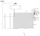
- FIG. 2 is a plan view of the adsorption/desorption treatment device with some adsorption/desorption members removed;
- FIG. 3 is an enlarged view of part C of FIG. 2;
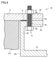
- 4 is an enlarged view of the mounting area in Embodiment 1.
- FIG. FIG. 11 is an enlarged view of a mounting area in Embodiment 2;
- FIG. 11 is an enlarged view of a mounting area in Embodiment 3;
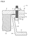
- FIG. 11 is an enlarged view of a mounting area in Embodiment 4;
- FIG. 1 is a diagram schematically showing the configuration of an organic solvent-containing gas treatment system in a reference example.
- a gas A to be treated containing an organic solvent passes through a gas to be treated line 101 and flows through an adsorption gas line 103 by a blower 102 for the gas to be treated.
- the liquid is sent to adsorption tanks 104A and 104B in the adsorption process.
- the organic solvent is adsorbed while passing through the adsorption/desorption elements 105A and 105B in the adsorption tank.
- the gas to be treated A becomes clean air B and is released into the atmosphere.
- the organic solvent adsorbed by the adsorption/desorption elements 105A and 105B in the adsorption tanks 104A and 104B which are in the desorption process by opening and closing the upper dampers 106A and 106B and the lower dampers 107A and 107B, passes through the water vapor line 108. Then, it is desorbed by water vapor C introduced from water vapor valves 109A and 109B, passed through a desorption water vapor line 110, introduced into a condenser 111 from a condenser inlet 111A, and cooled.
- the liquefied and condensed organic solvent is discharged from the condenser outlet 111B, sent to the separator 113 via the condensate line 112, separated into the separated waste water 113A and the organic solvent 113B, and recovered as the recovered solvent D.
- the uncondensed organic solvent in the condenser 111 and the separator 113 is introduced into the upstream side of the to-be-processed gas blower 102 via the return gas line 114 .
- FIG. 2 is an enlarged view of the mounting area.
- FIG. 3 is a plan view of the adsorption/desorption treatment apparatus with some adsorption/desorption members removed.
- FIG. 4 is an enlarged view of part C of FIG.
- the adsorption/desorption treatment apparatus 100 includes an adsorption/desorption member 15 having the adsorption/desorption elements 105A and 105B shown in FIG. 1 that adsorb and desorb an organic solvent.
- the adsorption/desorption elements 105A and 105B shown in FIG. 1 will be collectively described as an adsorption/desorption element 131.
- the adsorption/desorption member 15 includes a cylindrical adsorption/desorption element 131 and a flange provided on the upper surface of the adsorption/desorption element 131 and projecting outward from the edge of the adsorption/desorption element 131. a mounting plate 2 having a portion 2F.
- the adsorption/desorption member 15 includes a cylindrical adsorption/desorption element 131 and a flange provided on the upper surface of the adsorption/desorption element 131 and projecting outward from the edge of the adsorption/desorption element 131. a mounting plate 2 having a portion 2F.
- a plate-like member 31 including three openings 3A through which the adsorption/desorption members 15 are inserted, and upwardly from the plate-like member 31
- An annular standing wall 32 that stands up and surrounds the edge of the opening 3A, and an annular plate 33 that protrudes outward from the upper end of the annular standing wall 32 are provided.
- the plate member 31, the annular standing wall 32 and the annular plate 33 are integrally formed by press working. Alternatively, the annular standing wall 32 and the annular plate 33 may be fixed to the plate member 31 by welding.
- FIG. 3 shows a state in which the adsorption/desorption member 15 is attached to one of the three openings 3A.
- the adsorption/desorption member 15 is accommodated in the adsorption/desorption processing apparatus 100 in a suspended state by inserting the tubular adsorption/desorption element 131 into the opening hole 3A and overlapping the flange portion 2F and the annular plate 33 .
- FIG. 4 when the adsorption/desorption element 131 is housed inside the adsorption/desorption processing apparatus 100, a region provided at a position where the flange portion 2F and the annular plate 33 overlap is referred to as a mounting region. 2 and 4, the attachment area will be described as an attachment area 1A.
- the mounting area 1A includes a mounting plate 2, a plate member 31, an annular standing wall 32, an annular plate 33, a hexagon bolt 8, a nut 5, and a seal member 6. .
- the mounting plate 2 has a first hole portion 2a in the flange portion 2F.
- the annular plate 33 has a second hole 3a.
- the head 8a of the hexagon bolt 8 is directed downward, and the threaded portion 8b of the hexagon bolt 8 inserted through the second hole 3a and the first hole 2a is tightened with the nut 5 from the flange portion 2F side.
- a soft gasket for example, can be used for the sealing member 6 .
- the seal member 6 is arranged on the lower surface of the flange portion 2F at a position on the adsorption/desorption element 131 side when viewed from the hexagonal bolt 8 .
- the seal member 6 is annularly arranged around the aperture 3A. The seal member 6 is compressed between the flange portion 2F and the annular plate 33 when the adsorption/detachment member 15 is attached, thereby improving annular airtightness.
- the position connecting the flange portion 2F and the annular plate 33 is sealed to form a leakage blocking structure that blocks the leakage of raw gas or carrier gas from the annular plate 33 side to the flange portion 2F side.
- gas leakage in the attachment region 1A accompanying replacement of the adsorption/desorption member 15 can be prevented by forming the leak blocking structure. Therefore, unpurified gas is prevented from being discharged into the atmosphere, and the adsorption/desorption treatment apparatus 100 can be used for a long period of time simply by replacing the adsorption/desorption member 15 .
- FIG. 5 is an enlarged view of the attachment area in Embodiment 1.
- the mounting region 1B of Embodiment 1 includes a mounting plate 2, a plate member 31, an annular standing wall 32, an annular plate 33, a hexagon bolt 8, a nut 5, and a seal member 6.
- the mounting plate 2 has a first hole portion 2a in the flange portion 2F.
- the annular plate 33 has a second hole 3a.
- the head 8a of the hexagon bolt 8 is turned up, and the threaded portion 8b of the hexagon bolt 8 inserted through the first hole 2a and the second hole 3a is tightened with the nut 5 from the annular plate 33 side.
- a soft gasket for example, can be used for the sealing member 6 .
- the seal member 6 is arranged on the lower surface of the flange portion 2F at a position on the adsorption/desorption element 131 side when viewed from the hexagonal bolt 8 .
- the seal member 6 is annularly arranged around the aperture 3A. The seal member 6 is compressed between the flange portion 2F and the annular plate 33 when the adsorption/detachment member 15 is attached, thereby improving annular airtightness.
- the position connecting the flange portion 2F and the annular plate 33 is sealed to form a leakage blocking structure that blocks the leakage of raw gas or carrier gas from the annular plate 33 side to the flange portion 2F side.
- gas leakage from the attachment region 1B associated with the replacement of the adsorption/desorption member 15 can be prevented by forming the leak blocking structure. Therefore, unpurified gas is prevented from being discharged into the atmosphere, and the adsorption/desorption treatment apparatus 100 can be used for a long period of time simply by replacing the adsorption/desorption member 15 .
- FIG. 6 is an enlarged view of the mounting area in the second embodiment.
- a mounting region 1 ⁇ /b>C of the second embodiment includes a mounting plate 2 , a plate member 31 , an annular standing wall 32 , an annular plate 33 , a hexagon bolt 8 , a nut 5 and a seal member 6 .
- the mounting plate 2 has a first hole portion 2a in the flange portion 2F.
- the annular plate 33 has a threaded portion 3b. In the attachment region 1C, the head 8a of the hexagon bolt 8 is turned downward, and the threaded portion 8b of the hexagon bolt 8 is engaged with the threaded portion 3b.
- the threaded portion 8b of the hexagonal bolt 8 is inserted into the first hole 2a, and the threaded portion 8b of the inserted hexagonal bolt 8 is tightened with the nut 5 from the flange portion 2F side.
- a soft gasket for example, can be used for the sealing member 6 .
- the seal member 6 is arranged on the lower surface of the flange portion 2F at a position on the adsorption/desorption element 131 side when viewed from the hexagonal bolt 8 .
- the seal member 6 is annularly arranged around the aperture 3A. The seal member 6 is compressed between the flange portion 2F and the annular plate 33 when the adsorption/detachment member 15 is attached, thereby improving annular airtightness.
- the position connecting the flange portion 2F and the annular plate 33 is sealed to form a leakage blocking structure that blocks the leakage of raw gas or carrier gas from the annular plate 33 side to the flange portion 2F side.
- gas leakage from the attachment region 1A associated with the replacement of the adsorption/desorption member 15 can be prevented by forming the leak blocking structure. Therefore, unpurified gas is prevented from being discharged into the atmosphere, and the adsorption/desorption treatment apparatus 100 can be used for a long period of time simply by replacing the adsorption/desorption member 15 .
- FIG. 7 is an enlarged view of the mounting area in Embodiment 3.
- FIG. A mounting region 1D of the third embodiment includes a mounting plate 2, a plate member 31, an annular standing wall 32, an annular plate 33, a hexagonal bolt 8, a nut 5, and a sealing member 6.
- the mounting plate 2 has a first hole portion 2a in the flange portion 2F.
- the annular plate 33 has a second hole 3a.
- the head 8a of the hexagon bolt 8 is directed downward, and the threaded portion 8b of the hexagon bolt 8 inserted through the second hole 3a and the first hole 2a is tightened with the nut 5 from the flange portion 2F side.
- a hollow columnar space D is formed between the adsorption/desorption element 131 and the annular standing wall 32 in the mounting region 1D.
- Raw gas or carrier gas passes through the space D.
- a gap corresponding to the space portion D is formed on the side of the adsorption/desorption element 131 of the annular standing wall 32, and the adsorption/desorption element 131 is efficiently used up to the portion near the mounting plate 2. be able to.
- a soft gasket for example, can be used for the sealing member 6 .
- the seal member 6 is arranged on the lower surface of the flange portion 2F at a position on the adsorption/desorption element 131 side when viewed from the hexagonal bolt 8 .
- the seal member 6 is annularly arranged around the aperture 3A. The seal member 6 is compressed between the flange portion 2F and the annular plate 33 when the adsorption/detachment member 15 is attached, thereby improving annular airtightness.
- the position connecting the flange portion 2F and the annular plate 33 is sealed to form a leakage blocking structure that blocks the leakage of raw gas or carrier gas from the annular plate 33 side to the flange portion 2F side.
- gas leakage from the attachment region 1D associated with the replacement of the adsorption/desorption member 15 can be prevented by forming the leak blocking structure. Therefore, unpurified gas is prevented from being discharged into the atmosphere, and the adsorption/desorption treatment apparatus 100 can be used for a long period of time simply by replacing the adsorption/desorption member 15 .
- FIG. 8 is an enlarged view of the attachment area in Embodiment 4.
- FIG. A mounting region 1E of the fourth embodiment includes a mounting plate 2, a plate member 31, an annular standing wall 32, an annular plate 33, a hexagon bolt 8, a nut 5, and a seal member 6.
- the mounting plate 2 has a first hole portion 2a in the flange portion 2F.
- the annular plate 33 has a second hole 3a.
- the head 8a of the hexagon bolt 8 is directed downward, and the threaded portion 8b of the hexagon bolt 8 inserted through the second hole 3a and the first hole 2a is tightened with the nut 5 from the flange portion 2F side.
- the annular standing wall 32 has a shape extending obliquely upward from the plate-like member 31 to the annular plate 33 .
- a hollow truncated conical space E is formed between the adsorption/desorption element 131 and the annular standing wall 32 in the attachment region 1E.
- Raw gas or carrier gas passes through space E.
- a gap corresponding to the space portion E is formed on the side of the adsorption/desorption element 131 of the annular standing wall 32, and the adsorption/desorption element 131 is efficiently used up to a portion close to the mounting plate 2. be able to.
- a soft gasket for example, can be used for the sealing member 6 .
- the seal member 6 is arranged on the lower surface of the flange portion 2F at a position on the adsorption/desorption element 131 side when viewed from the hexagonal bolt 8 .
- the seal member 6 is annularly arranged around the aperture 3A. The seal member 6 is compressed between the flange portion 2F and the annular plate 33 when the adsorption/detachment member 15 is attached, thereby improving annular airtightness.
- the position connecting the flange portion 2F and the annular plate 33 is sealed to form a leakage blocking structure that blocks the leakage of raw gas or carrier gas from the annular plate 33 side to the flange portion 2F side.
- gas leakage from the attachment area 1E associated with the replacement of the adsorption/desorption member 15 can be prevented by forming the leak blocking structure. Therefore, unpurified gas is prevented from being discharged into the atmosphere, and the adsorption/desorption treatment apparatus 100 can be used for a long period of time simply by replacing the adsorption/desorption member 15 .
- the seal member 6 may be omitted. Also, an annular groove may be provided in the annular plate 33 to facilitate positioning of the seal member 6 .
- the shape of the adsorption/desorption element 131 may be a shape other than a cylindrical shape.
- the adsorption/desorption element 131 may have a hollow quadrangular prism structure.
- the shape of the mounting plate 2 may also be square according to the shape of the adsorption/desorption element 131 .
- the plurality of attachment areas may be arranged in a square shape in a plan view. In this manner, the arrangement of the attachment regions may be changed according to the shape of the adsorption/desorption element 131 .
- the annular plate 33 may be provided with the threaded portion 3b shown in the second embodiment.
- the hexagon bolt 8 may be arranged so that the head portion 8a is on the side of the mounting plate 2 as shown in the first embodiment.
- sealing tape may be wrapped around the threaded portion of each bolt. By wrapping the sealing tape, the airtightness can be improved and the bottle can be protected.
- the seal tape is made of, for example, polytetrafluoroethylene.
Landscapes
- Chemical & Material Sciences (AREA)
- Engineering & Computer Science (AREA)
- Analytical Chemistry (AREA)
- General Chemical & Material Sciences (AREA)
- Oil, Petroleum & Natural Gas (AREA)
- Chemical Kinetics & Catalysis (AREA)
- Environmental & Geological Engineering (AREA)
- Health & Medical Sciences (AREA)
- Biomedical Technology (AREA)
- Separation Of Gases By Adsorption (AREA)
Priority Applications (5)
| Application Number | Priority Date | Filing Date | Title |
|---|---|---|---|
| JP2022577657A JPWO2023037965A1 (https=) | 2021-09-07 | 2022-09-01 | |
| US18/689,174 US20240375035A1 (en) | 2021-09-07 | 2022-09-01 | Structure for attachment of adsorption and desorption member |
| EP22867287.9A EP4400199A1 (en) | 2021-09-07 | 2022-09-01 | Attachment structure for adsorption-desorption member |
| CN202280060458.9A CN117916006A (zh) | 2021-09-07 | 2022-09-01 | 吸附脱附部件的安装结构 |
| KR1020247010648A KR20240052818A (ko) | 2021-09-07 | 2022-09-01 | 흡탈착 부재의 설치 구조 |
Applications Claiming Priority (2)
| Application Number | Priority Date | Filing Date | Title |
|---|---|---|---|
| JP2021-145153 | 2021-09-07 | ||
| JP2021145153 | 2021-09-07 |
Publications (1)
| Publication Number | Publication Date |
|---|---|
| WO2023037965A1 true WO2023037965A1 (ja) | 2023-03-16 |
Family
ID=85506676
Family Applications (1)
| Application Number | Title | Priority Date | Filing Date |
|---|---|---|---|
| PCT/JP2022/033000 Ceased WO2023037965A1 (ja) | 2021-09-07 | 2022-09-01 | 吸脱着部材の取付構造 |
Country Status (7)
| Country | Link |
|---|---|
| US (1) | US20240375035A1 (https=) |
| EP (1) | EP4400199A1 (https=) |
| JP (1) | JPWO2023037965A1 (https=) |
| KR (1) | KR20240052818A (https=) |
| CN (1) | CN117916006A (https=) |
| TW (1) | TW202325381A (https=) |
| WO (1) | WO2023037965A1 (https=) |
Families Citing this family (1)
| Publication number | Priority date | Publication date | Assignee | Title |
|---|---|---|---|---|
| US20230330587A1 (en) * | 2020-09-11 | 2023-10-19 | Toyobo Co., Ltd. | Organic solvent recovery system |
Citations (9)
| Publication number | Priority date | Publication date | Assignee | Title |
|---|---|---|---|---|
| US2096851A (en) * | 1934-06-13 | 1937-10-26 | Bullard Co | Air purifier |
| JPS55500304A (https=) * | 1978-05-26 | 1980-05-22 | ||
| US4445912A (en) * | 1982-02-04 | 1984-05-01 | The Mike Volk Co., Inc. | Effluent air filtration apparatus |
| JPS60189318U (ja) * | 1984-05-23 | 1985-12-14 | 東洋紡績株式会社 | 廃ガスの吸着浄化装置における切替ダンパ−装置 |
| JPH03109625U (https=) * | 1990-02-20 | 1991-11-11 | ||
| JPH0537318U (ja) * | 1991-10-24 | 1993-05-21 | 大阪瓦斯株式会社 | 吸着塔 |
| JPH11123311A (ja) * | 1990-08-15 | 1999-05-11 | Osaka Gas Co Ltd | 溶剤回収装置 |
| CN211098282U (zh) | 2019-04-29 | 2020-07-28 | 东洋纺株式会社 | 回收系统 |
| CN212327833U (zh) | 2019-12-11 | 2021-01-12 | 东洋纺株式会社 | 回收装置以及回收系统 |
Family Cites Families (6)
| Publication number | Priority date | Publication date | Assignee | Title |
|---|---|---|---|---|
| US4522717A (en) * | 1983-06-24 | 1985-06-11 | Brust John E | Filter apparatus |
| JPH0685020U (ja) * | 1992-12-07 | 1994-12-06 | 石川島播磨重工業株式会社 | 除塵フィルタ |
| DK0781585T3 (da) * | 1995-12-29 | 2003-07-21 | Glatt Gmbh | Indretning til fjernelse af støv fra gas |
| US6921423B2 (en) * | 2003-07-21 | 2005-07-26 | Ingersoll-Rand Company | Separator tank assembly and method of manufacture |
| US8646534B2 (en) * | 2011-05-23 | 2014-02-11 | Richard R. Magden | Well head containment fitting device |
| KR102648977B1 (ko) | 2018-11-12 | 2024-03-20 | 엘지디스플레이 주식회사 | 유기발광 표시장치 |
-
2022
- 2022-09-01 CN CN202280060458.9A patent/CN117916006A/zh active Pending
- 2022-09-01 EP EP22867287.9A patent/EP4400199A1/en not_active Withdrawn
- 2022-09-01 US US18/689,174 patent/US20240375035A1/en active Pending
- 2022-09-01 KR KR1020247010648A patent/KR20240052818A/ko active Pending
- 2022-09-01 JP JP2022577657A patent/JPWO2023037965A1/ja active Pending
- 2022-09-01 WO PCT/JP2022/033000 patent/WO2023037965A1/ja not_active Ceased
- 2022-09-06 TW TW111133627A patent/TW202325381A/zh unknown
Patent Citations (9)
| Publication number | Priority date | Publication date | Assignee | Title |
|---|---|---|---|---|
| US2096851A (en) * | 1934-06-13 | 1937-10-26 | Bullard Co | Air purifier |
| JPS55500304A (https=) * | 1978-05-26 | 1980-05-22 | ||
| US4445912A (en) * | 1982-02-04 | 1984-05-01 | The Mike Volk Co., Inc. | Effluent air filtration apparatus |
| JPS60189318U (ja) * | 1984-05-23 | 1985-12-14 | 東洋紡績株式会社 | 廃ガスの吸着浄化装置における切替ダンパ−装置 |
| JPH03109625U (https=) * | 1990-02-20 | 1991-11-11 | ||
| JPH11123311A (ja) * | 1990-08-15 | 1999-05-11 | Osaka Gas Co Ltd | 溶剤回収装置 |
| JPH0537318U (ja) * | 1991-10-24 | 1993-05-21 | 大阪瓦斯株式会社 | 吸着塔 |
| CN211098282U (zh) | 2019-04-29 | 2020-07-28 | 东洋纺株式会社 | 回收系统 |
| CN212327833U (zh) | 2019-12-11 | 2021-01-12 | 东洋纺株式会社 | 回收装置以及回收系统 |
Also Published As
| Publication number | Publication date |
|---|---|
| TW202325381A (zh) | 2023-07-01 |
| EP4400199A1 (en) | 2024-07-17 |
| JPWO2023037965A1 (https=) | 2023-03-16 |
| CN117916006A (zh) | 2024-04-19 |
| KR20240052818A (ko) | 2024-04-23 |
| US20240375035A1 (en) | 2024-11-14 |
Similar Documents
| Publication | Publication Date | Title |
|---|---|---|
| JP2001187310A (ja) | 改良された封止部を有するバルブを備えた吸着作用による流体のサイクル処理用装置 | |
| KR101096596B1 (ko) | 휘발성 유기화합물 흡착탑 | |
| WO2023037965A1 (ja) | 吸脱着部材の取付構造 | |
| TWI734835B (zh) | 氫氣或氦氣之精製方法以及氫氣或氦氣之精製裝置 | |
| JP5766089B2 (ja) | 二酸化炭素回収精製方法及びシステム | |
| JP6905534B2 (ja) | 水素またはヘリウムの精製方法、および水素またはヘリウムの精製装置 | |
| WO2023037964A1 (ja) | 吸脱着部材の取付構造 | |
| KR20170001486U (ko) | 산업용 굴뚝 정화장치 | |
| CN213160083U (zh) | 一种可调式气体纯化器及气体充装系统 | |
| KR20250029766A (ko) | 이동식 휘발성 유기화합물 회수장치 및 방법 | |
| KR20050090774A (ko) | 저유소의 휘발성 유기화합물 회수장치 및 그 회수방법 | |
| EP4532083A1 (en) | An abatement system for treatment of exhaust gases of a vacuum processing system | |
| JPWO2023037965A5 (https=) | ||
| JP6058404B2 (ja) | 放射性物質の吸着装置 | |
| JP2002200410A (ja) | 不活性ガスを単離して回収する方法及び該方法を実施するための装置 | |
| CN213699138U (zh) | 活性炭高效除油器 | |
| KR102869989B1 (ko) | 휘발성 유기화합물 응축 시스템의 voc 흡탈착 장치 | |
| RU146571U1 (ru) | Адсорбер | |
| KR0155244B1 (ko) | 유해가스와 미세분진을 고효율로 제거하는 필터의 구조 | |
| CN219744380U (zh) | 用于沸石分子筛吸附节能装置 | |
| KR102450032B1 (ko) | 정전기 제거가 가능한 고효율 유증기 액화 회수장치 | |
| CN113120907B (zh) | 一种高纯二氧化碳提纯装置 | |
| RU206221U1 (ru) | Комбинированный адсорбер для отчистки газовых выбросов от диоксида серы | |
| CN209123610U (zh) | 一种具有废气处理功能的烟筒结构 | |
| CN210751990U (zh) | 一种膜分离和变压吸附联合处理装置 |
Legal Events
| Date | Code | Title | Description |
|---|---|---|---|
| WWE | Wipo information: entry into national phase |
Ref document number: 2022577657 Country of ref document: JP |
|
| 121 | Ep: the epo has been informed by wipo that ep was designated in this application |
Ref document number: 22867287 Country of ref document: EP Kind code of ref document: A1 |
|
| WWE | Wipo information: entry into national phase |
Ref document number: 18689174 Country of ref document: US |
|
| WWE | Wipo information: entry into national phase |
Ref document number: 202280060458.9 Country of ref document: CN |
|
| ENP | Entry into the national phase |
Ref document number: 20247010648 Country of ref document: KR Kind code of ref document: A |
|
| WWE | Wipo information: entry into national phase |
Ref document number: 2022867287 Country of ref document: EP |
|
| NENP | Non-entry into the national phase |
Ref country code: DE |
|
| ENP | Entry into the national phase |
Ref document number: 2022867287 Country of ref document: EP Effective date: 20240408 |