WO2023037419A1 - Procédé de commande de véhicule et véhicule - Google Patents
Procédé de commande de véhicule et véhicule Download PDFInfo
- Publication number
- WO2023037419A1 WO2023037419A1 PCT/JP2021/032914 JP2021032914W WO2023037419A1 WO 2023037419 A1 WO2023037419 A1 WO 2023037419A1 JP 2021032914 W JP2021032914 W JP 2021032914W WO 2023037419 A1 WO2023037419 A1 WO 2023037419A1
- Authority
- WO
- WIPO (PCT)
- Prior art keywords
- regeneration
- engine
- mot
- generator
- vehicle
- Prior art date
Links
- 238000000034 method Methods 0.000 title claims abstract description 42
- 230000008929 regeneration Effects 0.000 claims abstract description 180
- 238000011069 regeneration method Methods 0.000 claims abstract description 180
- 239000013618 particulate matter Substances 0.000 claims abstract description 9
- 239000000446 fuel Substances 0.000 claims description 39
- 230000001629 suppression Effects 0.000 claims description 36
- 230000003247 decreasing effect Effects 0.000 claims description 3
- 230000001172 regenerating effect Effects 0.000 description 45
- 230000008859 change Effects 0.000 description 20
- 238000010586 diagram Methods 0.000 description 17
- 230000001133 acceleration Effects 0.000 description 14
- 230000000052 comparative effect Effects 0.000 description 11
- 230000008569 process Effects 0.000 description 11
- 239000004071 soot Substances 0.000 description 11
- 230000007423 decrease Effects 0.000 description 10
- 238000002485 combustion reaction Methods 0.000 description 7
- 238000013021 overheating Methods 0.000 description 5
- 238000010248 power generation Methods 0.000 description 5
- 238000009825 accumulation Methods 0.000 description 3
- 230000008021 deposition Effects 0.000 description 3
- 239000007789 gas Substances 0.000 description 3
- 230000004044 response Effects 0.000 description 3
- 239000003054 catalyst Substances 0.000 description 2
- 238000007599 discharging Methods 0.000 description 2
- 230000007935 neutral effect Effects 0.000 description 2
- 238000013459 approach Methods 0.000 description 1
- QVGXLLKOCUKJST-UHFFFAOYSA-N atomic oxygen Chemical compound [O] QVGXLLKOCUKJST-UHFFFAOYSA-N 0.000 description 1
- 230000000994 depressogenic effect Effects 0.000 description 1
- 230000000694 effects Effects 0.000 description 1
- 230000005611 electricity Effects 0.000 description 1
- 238000002347 injection Methods 0.000 description 1
- 239000007924 injection Substances 0.000 description 1
- 239000001301 oxygen Substances 0.000 description 1
- 229910052760 oxygen Inorganic materials 0.000 description 1
- 238000002360 preparation method Methods 0.000 description 1
- 238000000746 purification Methods 0.000 description 1
- 230000009467 reduction Effects 0.000 description 1
- 230000007704 transition Effects 0.000 description 1
Images


Classifications
-
- B—PERFORMING OPERATIONS; TRANSPORTING
- B60—VEHICLES IN GENERAL
- B60W—CONJOINT CONTROL OF VEHICLE SUB-UNITS OF DIFFERENT TYPE OR DIFFERENT FUNCTION; CONTROL SYSTEMS SPECIALLY ADAPTED FOR HYBRID VEHICLES; ROAD VEHICLE DRIVE CONTROL SYSTEMS FOR PURPOSES NOT RELATED TO THE CONTROL OF A PARTICULAR SUB-UNIT
- B60W10/00—Conjoint control of vehicle sub-units of different type or different function
- B60W10/04—Conjoint control of vehicle sub-units of different type or different function including control of propulsion units
- B60W10/06—Conjoint control of vehicle sub-units of different type or different function including control of propulsion units including control of combustion engines
-
- B—PERFORMING OPERATIONS; TRANSPORTING
- B60—VEHICLES IN GENERAL
- B60W—CONJOINT CONTROL OF VEHICLE SUB-UNITS OF DIFFERENT TYPE OR DIFFERENT FUNCTION; CONTROL SYSTEMS SPECIALLY ADAPTED FOR HYBRID VEHICLES; ROAD VEHICLE DRIVE CONTROL SYSTEMS FOR PURPOSES NOT RELATED TO THE CONTROL OF A PARTICULAR SUB-UNIT
- B60W20/00—Control systems specially adapted for hybrid vehicles
- B60W20/10—Controlling the power contribution of each of the prime movers to meet required power demand
- B60W20/15—Control strategies specially adapted for achieving a particular effect
- B60W20/16—Control strategies specially adapted for achieving a particular effect for reducing engine exhaust emissions
-
- Y—GENERAL TAGGING OF NEW TECHNOLOGICAL DEVELOPMENTS; GENERAL TAGGING OF CROSS-SECTIONAL TECHNOLOGIES SPANNING OVER SEVERAL SECTIONS OF THE IPC; TECHNICAL SUBJECTS COVERED BY FORMER USPC CROSS-REFERENCE ART COLLECTIONS [XRACs] AND DIGESTS
- Y02—TECHNOLOGIES OR APPLICATIONS FOR MITIGATION OR ADAPTATION AGAINST CLIMATE CHANGE
- Y02T—CLIMATE CHANGE MITIGATION TECHNOLOGIES RELATED TO TRANSPORTATION
- Y02T10/00—Road transport of goods or passengers
- Y02T10/60—Other road transportation technologies with climate change mitigation effect
- Y02T10/62—Hybrid vehicles
Definitions
- the present invention relates to a vehicle control method and a vehicle.
- JP2018-065448A discloses a hybrid vehicle having an engine with an exhaust system fitted with a filter that removes particulate matter.
- a filter that removes particulate matter.
- a series hybrid vehicle is equipped with an engine, a generator, and a drive motor.
- the engine drives the generator to generate electricity, and the power generated by the generator drives the drive motor.
- deceleration can be obtained by regenerating the drive motor during deceleration. Regeneration can be performed when there is room for regeneration in terms of the power balance of the vehicle, that is, when there is a margin in the maximum acceptable power.
- the present invention has been made in view of such problems, and aims to suppress unintended changes in deceleration when regenerative deceleration is performed while fuel cut is prohibited.
- a vehicle control method suppresses the amount of regeneration by a drive motor when a condition for prohibiting engine fuel cut is satisfied in a series hybrid vehicle equipped with a filter that collects particulate matter in engine exhaust. Including.
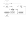
- FIG. 1 is a diagram showing a schematic configuration diagram of a vehicle.
- FIG. 2 is a diagram showing an execution region for fuel cut prohibition.
- FIG. 3 is an explanatory diagram of shift positions and drive modes.
- FIG. 4 is a diagram showing an example of regeneration suppression control in a flowchart.
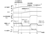
- FIG. 5 is a diagram showing a first example of a timing chart.
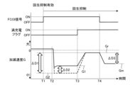
- FIG. 6 is an explanatory diagram of deceleration corresponding to the first example.
- FIG. 7 is a diagram showing a second example of the timing chart.
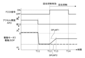
- FIG. 8 is a diagram showing a third example of the timing chart.
- FIG. 1 is a diagram showing a schematic configuration diagram of a vehicle 100.
- FIG. A vehicle 100 includes an engine 1 , a generator 2 , a drive motor 3 , a gear 4 , drive wheels 5 , a battery 6 , a GPF (Gasoline Particulate Filter) system 7 and a muffler 8 .
- Vehicle 100 is a series hybrid vehicle and has a series hybrid mode as a running mode. When the running mode is the series hybrid mode, the vehicle 100 drives the generator 2 with the engine 1 to generate power, and the electric power generated by the generator 2 drives the drive motor 3 .
- Engine 1 is an internal combustion engine and is assumed to be a gasoline engine.
- the engine 1 is connected to the generator 2 so as to be able to transmit power.
- the generator 2 is a motor generator for power generation, and performs motoring of the engine 1 in addition to power generation. Motoring is performed by driving the engine 1 in a stopped state by the generator 2 .
- the drive motor 3 is a drive motor generator and generates a drive force DP for the vehicle 100 .
- a driving force DP generated by the driving motor 3 is transmitted to the driving wheels 5 through the gear 4, which is a reduction gear.
- the drive motor 3 also regenerates energy by being driven by the power from the drive wheels 5 .
- the energy regenerated as electric power by the drive motor 3 can be charged to the battery 6 .
- the battery 6 stores the power generated by the generator 2 and the power regenerated by the drive motor 3.
- a discharge request SOC (State Of Charge) is set for the battery 6 .
- the SOC is a parameter that indicates the state of charge of the battery 6, and the discharge request SOC is set in advance as a value for specifying that the battery 6 is fully charged.
- the full charge of the battery 6 is defined by the discharge request SOC, and the full charge is defined, for example, when the SOC as the charging rate is 90%.
- the GPF system 7 is an exhaust purification system and is provided in the exhaust passage of the engine 1.
- the GPF system 7 has a GPF, that is, a gasoline particulate filter, and soot, which is particulate matter in exhaust gas from the engine 1, is collected by the GPF.
- GPF system 7 includes a GPF temperature sensor and a GPF differential pressure sensor.
- a GPF temperature sensor detects a GPF temperature T.
- the GPF temperature T is the floor temperature of the GPF, and the GPF temperature sensor detects, for example, the outlet exhaust gas temperature of the GPF as the actual temperature of the GPF temperature T.
- the GPF differential pressure sensor detects the differential pressure between the inlet exhaust pressure and the outlet exhaust pressure of the GPF.
- a GPF soot deposition amount S which is the amount of soot deposited on the GPF, is estimated based on the differential pressure.
- the GPF system 7 may contain a catalyst such as a three-way catalyst in addition to the GPF.
- a muffler 8 is provided in the exhaust passage of the engine 1 downstream of the GPF system 7 to reduce exhaust noise.
- the vehicle 100 further includes a motor controller 10, an engine controller 20, and a vehicle controller 30.
- the motor controller 10, the engine controller 20 and the vehicle controller 30 are connected so as to be able to communicate with each other.
- the motor controller 10 is composed of one or more microcomputers having a central processing unit (CPU), a read only memory (ROM), a random access memory (RAM) and an input/output interface (I/O interface).
- CPU central processing unit
- ROM read only memory
- RAM random access memory
- I/O interface input/output interface
- various controls are performed by executing programs stored in the ROM or RAM by the CPU. The same applies to the engine controller 20 and the vehicle controller 30 as well.
- the motor controller 10 controls the generator 2 and the drive motor 3.
- Motor controller 10 further includes a first inverter, which is the inverter for generator 2 , and a second inverter, which is the inverter for drive motor 3 . These inverters may be grasped as a configuration separate from the motor controller 10 .
- the motor controller 10 controls the generator 2 and the drive motor 3 by controlling the first inverter and the second inverter.
- the first inverter connects to the generator 2 and the battery 6 .
- the first inverter converts the alternating current supplied from the generator 2 into a direct current and supplies the direct current to the battery 6 .
- the battery 6 is charged with the electric power generated by the generator 2 .
- the first inverter further converts the direct current supplied from the battery 6 into alternating current and supplies the alternating current to the generator 2 .
- the generator 2 is driven by the power of the battery 6 .
- the second inverter, drive motor 3 and battery 6 as well. Signals such as current, voltage, and SOC are also input to the motor controller 10 from the generator 2 , the drive motor 3 , and the battery 6 .
- the engine controller 20 controls the engine 1. Signals from the GPF temperature sensor and the GPF differential pressure sensor are input to the engine controller 20 . These signals can be further input to vehicle controller 30 via engine controller 20 .
- the engine controller 20 prohibits fuel cut of the engine 1 based on the GPF temperature T and the GPF soot accumulation amount S (in other words, based on the GPF temperature T corresponding to the GPF soot accumulation amount S).
- FIG. 2 is a diagram showing the fuel cut prohibition region R.
- the fuel cut prohibition region R is preset according to the GPF soot deposit amount S and the GPF temperature T using map data.
- the fuel cut prohibition region R is defined as a region where the GPF temperature T is higher than the threshold Tref.
- the threshold Tref is a value for defining the fuel cut prohibition region R, and is set in advance according to the GPF soot deposition amount S. As the GPF soot accumulation amount S increases, the GPF becomes more likely to overheat due to soot combustion. Therefore, the threshold Tref is set to be smaller as the GPF soot deposition amount S is larger.
- the vehicle controller 30 comprehensively controls the engine 1, the generator 2, and the drive motor 3.
- the vehicle controller 30 includes an atmospheric pressure sensor 61 for detecting atmospheric pressure, an accelerator opening sensor 62 for detecting accelerator opening APO, a mode switch 63 for selecting a drive mode by driver operation, and a mode switch 63 for selecting a drive mode by driver operation.
- a signal from a shift position sensor 64 for detecting the shift position (range) is input.
- the vehicle controller 30 constitutes a controller 50 together with the motor controller 10 and the engine controller 20 .
- Fig. 3 is an explanatory diagram of shift positions and drive modes.
- Vehicle 100 further has a shifter 9 .
- the shifter 9 is a device for selecting a shift position by a driver's operation, and the driver's operation is performed by manipulating a shift lever or a switch to a gate corresponding to each shift position.
- the shifter 9 is a momentary shifter. In the momentary shifter 9, the shift lever released from the driver's operation autonomously returns to the home position, which is the neutral position.
- the shift positions selectable by the shifter 9 are P range (parking range), R range (reverse range), N range (neutral range), D range as the first forward range, and B range as the second forward range. including.
- the D range and B range are selected by operating the shift lever to the D/B gate common to these. By operating the shift lever to the D/B gate, the B range is selected when the D range is selected, and the D range is selected when the B range is selected. When a range other than the D range and the B range is selected, the D range is selected by operating the shift lever to the D/B gate.
- the drive modes selectable by the mode SW 63 include N mode, S mode and ECO mode.
- the N mode is a mode (normal mode) in which acceleration is performed by operating the accelerator pedal. Therefore, in the N mode, strong regenerative deceleration is not performed by operating the accelerator pedal.
- the S mode and the ECO mode are modes in which acceleration and regenerative deceleration are performed by operating the accelerator pedal (one-pedal mode), and the ECO mode is more suitable for fuel-efficient driving than the S mode.
- the drive mode is changed in the order of N mode, S mode and ECO mode each time the mode switch 63 is pressed, and returns to N mode after ECO mode.
- the drive motor 3 regenerates to generate deceleration. Deceleration is, in other words, negative acceleration and is indicated by a negative value.
- the regeneration limit amount magnitude of the regeneration limit
- the electric power obtained by regeneration is larger than that in the ECO mode, and the magnitude of deceleration generated is also larger.
- the ECO mode constitutes the first drive mode
- the S mode constitutes the second drive mode.
- deceleration can be obtained by regenerating the drive motor 3 during deceleration.
- Regeneration can be performed when there is room for regeneration in terms of the power balance of vehicle 100, that is, when there is a margin in the maximum acceptable power.
- controller 50 is programmed to perform the control described below.
- FIG. 4 is a flowchart showing an example of regeneration suppression control performed by the controller 50.
- FIG. FIG. 4 shows the case where the drive mode is the S mode.
- the controller 50 functionally implements a control section by performing the processing of the flowchart shown in FIG.
- the processing of the flowchart shown in FIG. 4 can be repeatedly executed.
- the processing of the flowchart shown in FIG. 4 can be performed by the vehicle controller 30, for example.
- step S1 the controller 50 determines whether the GPF temperature T is higher than the threshold Tref. That is, it is determined whether or not the fuel cut prohibition condition is satisfied. If the determination in step S1 is affirmative, the GPF status flag (in other words, the FCOI signal) is turned ON, and the process proceeds to step S2.
- the GPF status flag in other words, the FCOI signal
- step S2 the controller 50 determines whether regeneration is in progress. Whether or not regeneration is in progress can be determined by, for example, whether or not the target drive torque TQMOT_T is negative.
- the target drive torque TQ MOT _T can be set in advance by map data according to the accelerator opening APO and the vehicle speed VSP. During regeneration, the negative target drive torque TQ MOT _T, that is, the target regenerative torque is calculated based on the map data. If the determination in step S2 is negative, the process proceeds to step S3.
- step S3 the controller 50 enables regeneration suppression.
- Regeneration suppression is enabled by enabling the first regenerative limit torque TQ MOT _L1 out of the first regenerative limit torque TQ MOT _L1 and the second regenerative limit torque TQ MOT _L2.
- the second regenerative limit torque TQ MOT _L2 is valid regardless of whether the FCOI signal is ON.
- the first regenerative limit torque TQ MOT _L1 is the regenerative limit torque TQ MOT _L assuming that the GPF status flag is ON, that is, the fuel cut is prohibited.
- the second regeneration limit torque TQ MOT _L2 is the regeneration limit torque TQ MOT _L assuming that the GPF status flag is OFF, that is, the fuel cut is not prohibited, and the absolute value of the regeneration limit torque TQ MOT _L is the regeneration limit amount. Equivalent to.
- the second regeneration limit torque TQ MOT _L2 is set according to the system regeneration maximum electric power during regeneration.
- the system regenerated maximum power is the maximum power in absolute value that can be regenerated by vehicle 100 .
- Both the first regenerative limit torque TQ MOT _L1 and the second regenerative limit torque TQ MOT _L2 are set in the S mode.
- the driving torque TQ MOT of the drive motor 3 is reduced to the first regenerative limit torque TQ MOT _L1 and the second regenerative limit torque TQ MOT _L2 during regeneration. It is limited by the smaller absolute value.
- step S3 regardless of whether or not there is a discharge request according to the SOC, regardless of whether or not the battery 6 is fully charged, regeneration suppression is enabled. Therefore, in step S3, regeneration suppression is enabled even before the FCOI signal is ON and the battery is fully charged, ie, before the fuel cut prohibition state and the battery 6 fully charged state overlap. The same applies to step S5, which will be described later. After step S3, the process is temporarily terminated.
- step S6 the controller 50 determines whether or not the driving force DP of the driving motor 3 has exceeded a predetermined value DP1.
- the predetermined value DP1 is a judgment value for judging whether or not there is an acceleration request, and is set in advance.
- the predetermined value DP1 is positive and can be set slightly greater than zero.
- the process is temporarily terminated. Therefore, even if the GPF temperature T becomes equal to or lower than the threshold Tref during regeneration suppression and the FCOI signal changes from ON to OFF, regeneration suppression is not invalidated if the driving force DP is equal to or lower than the predetermined value DP1. If the determination in step S6 is affirmative, the process proceeds to step S7.
- step S7 the controller 50 disables regeneration suppression. Regeneration suppression is disabled by disabling the first regeneration limit torque TQ MOT _L1. After step S7, the process is temporarily terminated.
- step S2 determines whether regeneration is being suppressed. If regeneration suppression is effective, it is determined that regeneration is being suppressed, and the process is temporarily terminated. If regeneration suppression is disabled, it is determined that regeneration is not being suppressed, and the process proceeds to step S5.
- the controller 50 gradually decreases the amount of regeneration. That is, in this case, since regeneration is not being suppressed, regeneration is restricted by the second regeneration restriction torque TQ MOT _L2. Therefore, if the first regenerative limiting torque TQ MOT _L1 is enabled as it is, the absolute value of the deceleration suddenly decreases due to the regeneration limitation by the first regenerative limiting torque TQ MOT _L1. It can make you feel uncomfortable.
- step S5 the absolute value of the regeneration limit torque TQ MOT _L is gradually reduced to the first regeneration limit torque TQ MOT _L1. This suppresses an unintended change in deceleration that may occur when regeneration has already been performed before regeneration is suppressed.
- step S5 the process is temporarily terminated.
- FIG. 5 is a diagram showing a first example of a timing chart corresponding to FIG. FIG. 5 shows a case where the road on which the vehicle is traveling changes from an uphill to a downhill.
- the drive torque TQ MOT of the drive motor 3 indicated by the dashed line indicates the case of a comparative example in which regeneration suppression is not performed.
- the engine 1 Prior to timing T1, the engine 1 is in power generation operation at a constant ENG rotation speed NICE . Therefore, the GPF temperature T gradually increases. Drive torque TQ MOT is constant and positive and vehicle 100 is traveling uphill. Since the GPF temperature T is below the threshold Tref, the FCOI signal is OFF. SOC is dropping very slowly.
- the GPF temperature T becomes higher than the threshold Tref.
- the FCOI signal is turned ON.
- regeneration suppression is enabled.
- the drive torque TQ MOT is limited by the smaller absolute value of the first regenerative limit torque TQ MOT _L1 and the second regenerative limit torque TQ MOT _L2.
- the second regeneration limit torque TQ MOT _L2 is set to the driving torque TQ MOT when the driving torque TQ MOT is positive, that is, when regeneration is not performed.
- the drive torque TQ MOT of the drive motor 3 indicated by the dashed line changes while being limited to the second regeneration limit torque TQ MOT _L2. Therefore, the drive torque TQ MOT of the drive motor 3 indicated by the dashed line indicates the second regeneration limit torque TQ MOT _L2.
- the second regeneration limit torque TQ MOT _L2 is set to the regeneration limit torque TQ MOT _L21 between the timing T2 and the timing T3, therefore, when there is no discharge request during regeneration.
- the regeneration limit torque TQ MOT _L21 is the regeneration limit torque TQ MOT _L that is set during the regeneration of the second regeneration limit torque TQ MOT _L2 when there is no discharge request.
- the first regeneration limit torque TQ MOT _L1 indicated by the two-dot dashed line is set to the regeneration limit torque TQ MOT _L21 when the drive torque TQ MOT is positive.
- the first regenerative limit torque TQ MOT _L1 is gradually reduced in absolute value from regenerative limit torque TQ MOT _L21 to regenerative limit torque TQ MOT _L11.
- the regenerative limit torque TQ MOT _L11 is a regenerative limit torque TQ MOT _L that is set during regeneration of the first regenerative limit torque TQ MOT _L1 when the FCOI signal is turned ON.
- the regeneration limit torque TQ MOT _L11 is set to be smaller than the regeneration limit torque TQ MOT _L21 in absolute value. In other words, the regeneration limit torque TQ MOT _L21 is set to be larger in absolute value than the regeneration limit torque TQ MOT _L11.
- Regeneration limit torque TQ MOT _L21 is the maximum value of regeneration limit torque TQ MOT _L set in vehicle 100 as an absolute value.
- the absolute value of the regeneration limit torque TQ MOT _L11 corresponds to the first regeneration limit amount
- the absolute value of the regeneration limit torque TQ MOT _L21 corresponds to the second regeneration limit amount.
- the vehicle 100 approaches a downward slope and the accelerator is turned off. In other words, there is no need to depress the accelerator pedal.
- the drive torque TQ MOT begins to decrease accordingly and becomes negative. Therefore, regeneration is started, and the SOC increases according to the regeneration. Since the drive mode is the S mode, the drive torque TQ MOT is greatly reduced in absolute value. However, since regeneration is being suppressed, the drive torque TQ MOT is limited by the first regeneration limit torque TQ MOT _L1 and does not reach the second regeneration limit torque TQ MOT _L2.
- the drive torque TQ MOT is limited by the first regenerative limit torque TQ MOT _L1 while the first regenerative limit torque TQ MOT _L1 is changing from the regenerative limit torque TQ MOT _L21 to the regenerative limit torque TQ MOT _L11. Then, the drive torque TQ MOT changes while being limited by the first regenerative limit torque TQ MOT _L1 to become the regenerative limit torque TQ MOT _L11.
- the retard discharge is an example of a power consumption operation in which the generator 2 drives the engine 1 to generate negative engine torque while the engine 1 performs combustion.
- the engine 1 and the generator 2 create a state of engine torque ⁇ friction torque, so that the battery 6 is discharged while the engine 1 performs combustion.
- the ignition timing is retarded at this time, and the engine 1 performs combustion. In this case, the combustion slows down and the engine torque decreases, so it is easy to create a state of engine torque ⁇ friction torque.
- the retard discharge is performed by the controller 50 when there is a discharge request while the fuel cut of the engine 1 is prohibited, that is, when the FCOI signal is ON.
- By performing retarded discharge it is possible to discharge the battery 6 while suppressing overheating of the GPF even when the battery is fully charged.
- an engine 1 that performs retard combustion is driven by a generator 2 . Therefore, when the retard discharge starts, the ENG rotation speed NICE increases.
- the second regeneration limit torque TQ MOT _L2 changes during regeneration according to the power consumption of the engine 1 (in other words, the power consumption of the power generation unit composed of the engine 1 and the generator 2).
- the second regenerative limit torque TQ MOT _L2 is the regenerative limit torque TQ MOT _Lr during retard discharge during retard discharge, and the regenerative limit torque TQ MOT _Lm during motoring during motoring. Both of the regeneration limit torque TQ MOT _Lr and the regeneration limit torque TQ MOT _Lm are smaller than the regeneration limit torque TQ MOT _L21 in absolute value.
- the drive torque TQ MOT is limited by the smaller absolute value of the effective first regeneration limit torque TQ MOT _L1 and the second regeneration limit torque TQ MOT _L2.
- the regenerative limit torque TQ MOT _Lr and the regenerative limit torque TQ MOT _Lm, which are the second regenerative limit torque TQ MOT _L2, are smaller in absolute value than the regenerative limit torque TQ MOT _L11, which is the first regenerative limit torque TQ MOT _L1.
- the transition of the regeneration limit torque TQ MOT _L from the first regeneration limit torque TQ MOT _L1 to the second regeneration limit torque TQ MOT _L2 starts. .
- the drive torque TQ MOT rises to the regeneration limit torque TQ MOT _Lr during retard discharge. Since the regeneration limit torque TQ MOT _Lr during retard discharge is negative, deceleration continues even during retard discharge.
- the GPF temperature T becomes equal to or lower than the threshold Tref.
- the FCOI signal becomes OFF.
- motoring is performed because fuel cut is not prohibited.
- the ENG rotation speed N ICE decreases compared to that during retard discharge, and the drive torque TQ MOT decreases to the regeneration limit torque TQ MOT _Lm during motoring.
- a deceleration that is larger in absolute value than during retard discharge is ensured.
- FIG. 6 is an explanatory diagram of deceleration corresponding to the first example shown in FIG. FIG. 6 shows the FCOI signal, full charge flag and acceleration/deceleration G as parameters.
- the acceleration/deceleration G is the acceleration or deceleration in the longitudinal direction of the vehicle, and a negative value indicates deceleration.
- Acceleration/deceleration G indicated by a dashed line indicates the case of the comparative example, as in FIG.
- a deceleration G1 and a deceleration G2 indicate deceleration corresponding to the regeneration limit torque TQ MOT _L11 and the regeneration limit torque TQ MOT _L21.
- Deceleration Gr and deceleration Gm indicate deceleration corresponding to regeneration limit torque TQ MOT _Lr during retard discharge and regeneration limit torque TQ MOT _Lm during motoring.
- the acceleration/deceleration G is suppressed to a deceleration G1 that is smaller in absolute value than the deceleration G2. Therefore, even if the full charge flag is turned ON and the retard discharge is started, the magnitude of the deceleration change is the difference ⁇ D1 ⁇ the difference ⁇ D2 (the difference ⁇ D2 is the absolute value of the deceleration G2 ⁇ the absolute value of the deceleration G1). suppressed. As a result, unintended changes in deceleration that may give the driver a sense of discomfort are suppressed.
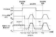
- FIG. 7 is a diagram showing a second example of a timing chart corresponding to FIG. FIG. 7 shows the case where the FCOI signal is turned ON while the accelerator is OFF.
- the driving force DP of the driving motor 3 indicated by the dashed line shows the case of the comparative example, as in FIG.
- the drive force DP can be obtained based on a drive force map in which the target drive force is set according to the accelerator opening APO and the vehicle speed VSP.
- the drive force limit value DPLMT2 indicates the drive force limit value DPLMT when regeneration suppression is not performed, that is, in the case of the comparative example, and corresponds to the regeneration limit torque TQ MOT_L21 .
- the amount of regeneration is gradually reduced.
- the amount of regeneration is decreased by gradually reducing the absolute value of the regeneration limit torque TQ MOT _L from the second regeneration limit torque TQ MOT _L2 to the first regeneration limit torque TQ MOT _L1.
- the driving force limit value DPLMT1 indicates the driving force limit value DPLMT when regeneration is suppressed, that is, in the present embodiment, and corresponds to the regeneration limit torque TQ MOT_L11 .
- FIG. 8 is a diagram showing a third example of the timing chart corresponding to FIG. FIG. 8 shows a case in which the accelerator is repeatedly turned on and off in response to changes in the slope of the road on which the vehicle is traveling.
- the driving force DP indicated by the dashed line indicates the case of the comparative example, as in FIG.
- the FCOI signal turns ON while driving uphill, and regeneration is suppressed.
- the accelerator opening APO becomes zero in response to approaching the downhill. As a result, the driving force DP also becomes negative, and regeneration is performed.
- the driving force DP becomes smaller than the driving force limit value DPLMT1 as indicated by the dashed line.
- the driving force DP obtained based on the driving force map in the case of the comparative example does not reach the driving force limit value DPLMT2.
- the driving force DP is suppressed to the driving force limit value DPLMT1 by regeneration suppression.
- the accelerator pedal begins to be depressed as the gradient of the road surface changes from downward to upward.
- the accelerator opening APO and the driving force DP gradually increase, and when the accelerator opening APO becomes constant, the driving force DP also becomes constant.
- the depression of the accelerator pedal is eased as the road surface slopes downward again, and accordingly the accelerator opening APO and the driving force DP gradually decrease.
- the accelerator opening APO finally becomes zero, and the driving force DP finally becomes the driving force limit value DPLMT1.
- the FCOI signal turns OFF, and the fuel cut prohibition condition is no longer satisfied. Therefore, since the situation in which the FCOI signal is ON does not overlap with the situation in which the battery is fully charged, it is possible to invalidate the regeneration suppression performed in preparation for such a situation. However, if regeneration suppression is disabled at timing T25, driving force limit value DPLMT1 is disabled, resulting in a drop in driving force DP. As a result, an unintended change in deceleration occurs that can give the driver a sense of discomfort.
- regeneration suppression is continued until timing T25 when the FCOI signal turns OFF, and regeneration suppression is disabled when the driving force DP exceeds the predetermined value DP1 at timing T26.
- the regeneration suppression can be disabled after confirming the acceleration according to the driver's acceleration request, so an unintended change in deceleration occurs when the regeneration suppression is disabled. can be prevented.
- the vehicle 100 includes an engine 1, a generator 2, and a drive motor 3.
- the engine 1 drives the generator 2 to generate power, the power generated by the generator 2 drives the drive motor 3, and the engine 1 emits exhaust gas.
- It has a GPF system 7 that collects the soot, which is the particulate matter inside.
- the control method of the vehicle 100 is to perform motoring by driving the engine 1 in the operation stop state by the generator 2, thereby cutting the fuel of the engine 1 and consuming electric power. It includes prohibiting the fuel cut of the engine 1 based on T, and suppressing the amount of regeneration by the drive motor 3 when the FCOI signal is turned ON, that is, when the condition for prohibiting the fuel cut of the engine 1 is satisfied.
- this method it is possible to reduce the deceleration in advance by the absolute value before the situation where the FCOI signal is ON during deceleration and the situation where the battery is fully charged overlap. Therefore, when the FCOI signal is ON and the battery is fully charged, regeneration is performed according to the discharge that can be performed. A change in deceleration can be suppressed by reducing the difference in deceleration before and after charging. As a result, it is possible to suppress unintended changes in deceleration that may give the driver a sense of discomfort.
- the FCOI signal when the FCOI signal is turned ON during regeneration by the drive motor 3, the amount of regeneration is gradually decreased. According to such a method, even when the FCOI signal is turned ON during regeneration, the change in deceleration caused by the suppression of regeneration can be moderated to suppress an unintended change in deceleration that may give the driver a sense of discomfort.
- regeneration suppression is continued until timing T25 when the FCOI signal is turned OFF, and regeneration suppression is disabled when driving force DP exceeds predetermined value DP1 at timing T26.
- Vehicle 100 has regeneration limit torque TQ MOT _L11 and regeneration limit torque TQ MOT _L21 larger in absolute value than regeneration limit torque TQ MOT _L11 as regeneration limit torque TQ MOT _L.
- the FCOI signal is turned ON, by enabling the regeneration limiting torque TQ MOT _L11, the amount of regeneration is suppressed more than when the FCOI signal is OFF.
- the regeneration limit torque TQ MOT _L in consideration of drivability as the regeneration limit torque TQ MOT _L11, the change in deceleration when the FCOI signal is ON and the battery is fully charged can be appropriately controlled. can be suppressed to
- the vehicle 100 has an ECO mode and an S mode in which the regenerative limit torque TQ MOT _L is set larger in absolute value than in the ECO mode, and the regenerative limit torque TQ MOT _L11 and the regenerative limit torque TQ MOT _L21 are set in the S mode. .
- the S mode a deceleration with a larger absolute value than in the ECO mode occurs at the start of regeneration, so the change in deceleration when the FCOI signal is ON and the battery is fully charged tends to give the driver a sense of discomfort.
- the regeneration limit torque TQ MOT _L 21 is the maximum absolute value of the regeneration limit torque TQ MOT _L set in the vehicle 100 . According to this method, as a result of performing regeneration with the regeneration limit torque TQ MOT_L21 as in the case of the comparative example, it is possible to prevent a large change in deceleration from occurring when the FCOI signal is ON and the battery is fully charged. Since it can be avoided, it is of great significance to suppress unintended changes in deceleration.
- the fuel cut prohibition condition is a condition determined based on the GPF temperature T. According to such a method, as a result of the situation of full charge overlapping the situation where fuel cut is prohibited due to the GPF temperature T, unintended change in deceleration that can occur when discharging cannot be performed by motoring is suppressed. A possible method is obtained.
- the ignition timing is retarded and the engine 1 burns while the generator 2 drives the engine 1 to generate a negative engine torque. is performed as a power consumption operation.
- the retarded discharge performed as power consumption operation the deceleration obtained by regeneration is smaller in absolute value than in the case of discharging in motoring. That is, in this case, the difference in deceleration before and after full charge tends to increase unless regeneration is suppressed. Therefore, in this case, it is of great significance to suppress unintended changes in deceleration.
- the power consumption operation may be a negative torque operation in which the generator 2 drives the engine 1 during idling to generate negative torque in the engine 1 .
Abstract
Priority Applications (2)
| Application Number | Priority Date | Filing Date | Title |
|---|---|---|---|
| CN202180102005.3A CN117916136A (zh) | 2021-09-07 | 2021-09-07 | 车辆的控制方法以及车辆 |
| PCT/JP2021/032914 WO2023037419A1 (fr) | 2021-09-07 | 2021-09-07 | Procédé de commande de véhicule et véhicule |
Applications Claiming Priority (1)
| Application Number | Priority Date | Filing Date | Title |
|---|---|---|---|
| PCT/JP2021/032914 WO2023037419A1 (fr) | 2021-09-07 | 2021-09-07 | Procédé de commande de véhicule et véhicule |
Publications (1)
| Publication Number | Publication Date |
|---|---|
| WO2023037419A1 true WO2023037419A1 (fr) | 2023-03-16 |
Family
ID=85507309
Family Applications (1)
| Application Number | Title | Priority Date | Filing Date |
|---|---|---|---|
| PCT/JP2021/032914 WO2023037419A1 (fr) | 2021-09-07 | 2021-09-07 | Procédé de commande de véhicule et véhicule |
Country Status (2)
| Country | Link |
|---|---|
| CN (1) | CN117916136A (fr) |
| WO (1) | WO2023037419A1 (fr) |
Citations (5)
| Publication number | Priority date | Publication date | Assignee | Title |
|---|---|---|---|---|
| JP2004225564A (ja) * | 2003-01-20 | 2004-08-12 | Hitachi Unisia Automotive Ltd | ハイブリッド車両の制御装置 |
| JP2018065448A (ja) | 2016-10-19 | 2018-04-26 | トヨタ自動車株式会社 | ハイブリッド自動車 |
| JP2020104668A (ja) * | 2018-12-27 | 2020-07-09 | トヨタ自動車株式会社 | 車両の制御装置 |
| JP2020111164A (ja) * | 2019-01-11 | 2020-07-27 | トヨタ自動車株式会社 | ハイブリッド自動車 |
| JP2021054331A (ja) * | 2019-09-30 | 2021-04-08 | ダイハツ工業株式会社 | 電動車両用制御装置 |
-
2021
- 2021-09-07 CN CN202180102005.3A patent/CN117916136A/zh active Pending
- 2021-09-07 WO PCT/JP2021/032914 patent/WO2023037419A1/fr active Application Filing
Patent Citations (5)
| Publication number | Priority date | Publication date | Assignee | Title |
|---|---|---|---|---|
| JP2004225564A (ja) * | 2003-01-20 | 2004-08-12 | Hitachi Unisia Automotive Ltd | ハイブリッド車両の制御装置 |
| JP2018065448A (ja) | 2016-10-19 | 2018-04-26 | トヨタ自動車株式会社 | ハイブリッド自動車 |
| JP2020104668A (ja) * | 2018-12-27 | 2020-07-09 | トヨタ自動車株式会社 | 車両の制御装置 |
| JP2020111164A (ja) * | 2019-01-11 | 2020-07-27 | トヨタ自動車株式会社 | ハイブリッド自動車 |
| JP2021054331A (ja) * | 2019-09-30 | 2021-04-08 | ダイハツ工業株式会社 | 電動車両用制御装置 |
Also Published As
| Publication number | Publication date |
|---|---|
| CN117916136A (zh) | 2024-04-19 |
Similar Documents
| Publication | Publication Date | Title |
|---|---|---|
| JP6919720B2 (ja) | ハイブリッド車両の制御方法、及び、制御装置 | |
| JP3715158B2 (ja) | エンジンの停止・始動制御装置 | |
| JP5338351B2 (ja) | ハイブリッド車両の制御装置 | |
| JP2011239605A (ja) | 車両の制御装置 | |
| WO2007080729A1 (fr) | Véhicule hybride et procédé de commande de celui-ci | |
| WO2007069584A1 (fr) | Automobile hybride et son procédé de commande | |
| JP6927328B2 (ja) | ハイブリッド車両の制御方法、及び、制御装置 | |
| JP5808997B2 (ja) | ハイブリッド自動車の制御装置 | |
| JP4026133B2 (ja) | ハイブリッド車両の制御装置 | |
| WO2019116588A1 (fr) | Procédé de commande pour véhicule hybride et appareil de commande pour véhicule hybride | |
| JP5239841B2 (ja) | ハイブリッド車両の制御装置 | |
| JP2008044554A (ja) | 車両の制動制御装置 | |
| JP2008094238A (ja) | ハイブリッド車の制御装置 | |
| JP2009029261A (ja) | 車両用駆動力制御装置 | |
| JP2020104668A (ja) | 車両の制御装置 | |
| JP3891130B2 (ja) | 車両の減速制御装置 | |
| WO2023037419A1 (fr) | Procédé de commande de véhicule et véhicule | |
| JP2004270512A (ja) | ハイブリッド車両の制御装置 | |
| JP5741068B2 (ja) | 電動車両 | |
| WO2023037420A1 (fr) | Procédé de commande de véhicule et véhicule | |
| WO2023037421A1 (fr) | Procédé de commande de véhicule et véhicule | |
| JP2004034844A (ja) | 車両のトルク制御装置及びトルク制御方法 | |
| JP2004211575A (ja) | 車輌の制御装置 | |
| JP2005304201A (ja) | ハイブリッド車両のモータトルク制御方法 | |
| JP2005341644A (ja) | ハイブリッド車両の制御装置 |
Legal Events
| Date | Code | Title | Description |
|---|---|---|---|
| 121 | Ep: the epo has been informed by wipo that ep was designated in this application |
Ref document number: 21956264 Country of ref document: EP Kind code of ref document: A1 |
|
| WWE | Wipo information: entry into national phase |
Ref document number: 2023546602 Country of ref document: JP |
|
| WWE | Wipo information: entry into national phase |
Ref document number: 2401001345 Country of ref document: TH |
|
| REG | Reference to national code |
Ref country code: BR Ref legal event code: B01A Ref document number: 112024003886 Country of ref document: BR |
|
| WWE | Wipo information: entry into national phase |
Ref document number: 2021956264 Country of ref document: EP |
|
| NENP | Non-entry into the national phase |
Ref country code: DE |
|
| ENP | Entry into the national phase |
Ref document number: 2021956264 Country of ref document: EP Effective date: 20240408 |