WO2023037421A1 - Procédé de commande de véhicule et véhicule - Google Patents
Procédé de commande de véhicule et véhicule Download PDFInfo
- Publication number
- WO2023037421A1 WO2023037421A1 PCT/JP2021/032916 JP2021032916W WO2023037421A1 WO 2023037421 A1 WO2023037421 A1 WO 2023037421A1 JP 2021032916 W JP2021032916 W JP 2021032916W WO 2023037421 A1 WO2023037421 A1 WO 2023037421A1
- Authority
- WO
- WIPO (PCT)
- Prior art keywords
- engine
- generator
- torque
- eng
- power
- Prior art date
Links
- 238000000034 method Methods 0.000 title claims abstract description 24
- 239000000446 fuel Substances 0.000 claims abstract description 78
- 238000002485 combustion reaction Methods 0.000 claims abstract description 14
- 239000013618 particulate matter Substances 0.000 claims abstract description 9
- 238000002347 injection Methods 0.000 claims description 7
- 239000007924 injection Substances 0.000 claims description 7
- 239000007789 gas Substances 0.000 description 56
- 230000001172 regenerating effect Effects 0.000 description 42
- 230000008929 regeneration Effects 0.000 description 35
- 238000011069 regeneration method Methods 0.000 description 35
- 238000010586 diagram Methods 0.000 description 29
- 238000010248 power generation Methods 0.000 description 21
- 239000004071 soot Substances 0.000 description 13
- 230000007423 decrease Effects 0.000 description 12
- 230000008569 process Effects 0.000 description 10
- 238000012545 processing Methods 0.000 description 10
- QVGXLLKOCUKJST-UHFFFAOYSA-N atomic oxygen Chemical compound [O] QVGXLLKOCUKJST-UHFFFAOYSA-N 0.000 description 9
- 238000013021 overheating Methods 0.000 description 9
- 239000001301 oxygen Substances 0.000 description 9
- 229910052760 oxygen Inorganic materials 0.000 description 9
- 241001125929 Trisopterus luscus Species 0.000 description 8
- 230000008859 change Effects 0.000 description 7
- 230000007704 transition Effects 0.000 description 7
- 230000004044 response Effects 0.000 description 5
- 238000009825 accumulation Methods 0.000 description 4
- 230000008021 deposition Effects 0.000 description 4
- 230000001133 acceleration Effects 0.000 description 3
- 101150100956 VSP2 gene Proteins 0.000 description 2
- 230000004913 activation Effects 0.000 description 2
- 239000003054 catalyst Substances 0.000 description 2
- 230000005611 electricity Effects 0.000 description 2
- 230000012447 hatching Effects 0.000 description 2
- 230000007935 neutral effect Effects 0.000 description 2
- 238000013459 approach Methods 0.000 description 1
- 238000012937 correction Methods 0.000 description 1
- 230000003247 decreasing effect Effects 0.000 description 1
- 238000007599 discharging Methods 0.000 description 1
- 230000000694 effects Effects 0.000 description 1
- 230000007613 environmental effect Effects 0.000 description 1
- 238000007562 laser obscuration time method Methods 0.000 description 1
- 238000000746 purification Methods 0.000 description 1
- 230000009467 reduction Effects 0.000 description 1
- 230000000979 retarding effect Effects 0.000 description 1
Images


Classifications
-
- B—PERFORMING OPERATIONS; TRANSPORTING
- B60—VEHICLES IN GENERAL
- B60W—CONJOINT CONTROL OF VEHICLE SUB-UNITS OF DIFFERENT TYPE OR DIFFERENT FUNCTION; CONTROL SYSTEMS SPECIALLY ADAPTED FOR HYBRID VEHICLES; ROAD VEHICLE DRIVE CONTROL SYSTEMS FOR PURPOSES NOT RELATED TO THE CONTROL OF A PARTICULAR SUB-UNIT
- B60W10/00—Conjoint control of vehicle sub-units of different type or different function
- B60W10/04—Conjoint control of vehicle sub-units of different type or different function including control of propulsion units
- B60W10/06—Conjoint control of vehicle sub-units of different type or different function including control of propulsion units including control of combustion engines
-
- B—PERFORMING OPERATIONS; TRANSPORTING
- B60—VEHICLES IN GENERAL
- B60W—CONJOINT CONTROL OF VEHICLE SUB-UNITS OF DIFFERENT TYPE OR DIFFERENT FUNCTION; CONTROL SYSTEMS SPECIALLY ADAPTED FOR HYBRID VEHICLES; ROAD VEHICLE DRIVE CONTROL SYSTEMS FOR PURPOSES NOT RELATED TO THE CONTROL OF A PARTICULAR SUB-UNIT
- B60W10/00—Conjoint control of vehicle sub-units of different type or different function
- B60W10/04—Conjoint control of vehicle sub-units of different type or different function including control of propulsion units
- B60W10/08—Conjoint control of vehicle sub-units of different type or different function including control of propulsion units including control of electric propulsion units, e.g. motors or generators
-
- B—PERFORMING OPERATIONS; TRANSPORTING
- B60—VEHICLES IN GENERAL
- B60W—CONJOINT CONTROL OF VEHICLE SUB-UNITS OF DIFFERENT TYPE OR DIFFERENT FUNCTION; CONTROL SYSTEMS SPECIALLY ADAPTED FOR HYBRID VEHICLES; ROAD VEHICLE DRIVE CONTROL SYSTEMS FOR PURPOSES NOT RELATED TO THE CONTROL OF A PARTICULAR SUB-UNIT
- B60W20/00—Control systems specially adapted for hybrid vehicles
- B60W20/10—Controlling the power contribution of each of the prime movers to meet required power demand
- B60W20/15—Control strategies specially adapted for achieving a particular effect
- B60W20/16—Control strategies specially adapted for achieving a particular effect for reducing engine exhaust emissions
-
- Y—GENERAL TAGGING OF NEW TECHNOLOGICAL DEVELOPMENTS; GENERAL TAGGING OF CROSS-SECTIONAL TECHNOLOGIES SPANNING OVER SEVERAL SECTIONS OF THE IPC; TECHNICAL SUBJECTS COVERED BY FORMER USPC CROSS-REFERENCE ART COLLECTIONS [XRACs] AND DIGESTS
- Y02—TECHNOLOGIES OR APPLICATIONS FOR MITIGATION OR ADAPTATION AGAINST CLIMATE CHANGE
- Y02T—CLIMATE CHANGE MITIGATION TECHNOLOGIES RELATED TO TRANSPORTATION
- Y02T10/00—Road transport of goods or passengers
- Y02T10/60—Other road transportation technologies with climate change mitigation effect
- Y02T10/62—Hybrid vehicles
Definitions
- the present invention relates to a vehicle control method and a vehicle.
- JP2018-065448A discloses a hybrid vehicle having an engine with an exhaust system fitted with a filter that removes particulate matter.
- a filter that removes particulate matter.
- a series hybrid vehicle is equipped with an engine, a generator, and a drive motor.
- the engine drives the generator to generate electricity, and the power generated by the generator drives the drive motor.
- deceleration can be obtained by regenerating the drive motor during deceleration. Regeneration can be performed when there is room for regeneration in terms of the power balance of the vehicle, that is, when there is a margin in the maximum acceptable power.
- the present invention has been made in view of such problems, and it is an object of the present invention to protect the filter even if the engine runs out of fuel during power consumption operation while fuel cut is prohibited.
- a vehicle control method is a series hybrid vehicle equipped with a filter that collects particulate matter in exhaust gas from an engine. and driving the engine with a power generator to generate negative ENG torque in the engine while fuel cut is prohibited. and stopping the generator if it detects that the engine is not injecting fuel.
- FIG. 1 is a diagram showing a schematic configuration diagram of a vehicle.
- FIG. 2 is a diagram showing an execution region for fuel cut prohibition.
- FIG. 3 is an explanatory diagram of shift positions and drive modes.
- FIG. 4 is the first block diagram showing the processing of the vehicle controller.
- FIG. 5 is a second block diagram showing the processing of the vehicle controller.
- FIG. 6 is a diagram showing map data of the target ENG rotation speed.
- FIG. 7 is a diagram showing a power change rate according to vehicle speed.
- FIG. 8 is a diagram showing an example of discharge control in the form of a flowchart.
- FIG. 9 is a diagram showing a first example of a timing chart corresponding to FIG.
- FIG. 10 is a diagram showing a second example of a timing chart corresponding to FIG.
- FIG. 9 is a diagram showing a first example of a timing chart corresponding to FIG.
- FIG. 10 is a diagram showing a second example of a timing chart corresponding to FIG. FIG.
- FIG. 11 is a diagram showing a third example of a timing chart corresponding to FIG.
- FIG. 12 is a block diagram showing the processing of gas shortage response control.
- FIG. 13 is a diagram showing an example of map data of the gas shortage determination torque.
- FIG. 14 is a diagram showing an example of the out-of-gas response control in the form of a flowchart.
- 15 is a diagram showing an example of a timing chart corresponding to FIG. 14.
- FIG. 1 is a diagram showing a schematic configuration diagram of a vehicle 100.
- FIG. A vehicle 100 includes an engine 1 , a generator 2 , a drive motor 3 , a gear 4 , drive wheels 5 , a battery 6 , a GPF (Gasoline Particulate Filter) system 7 and a muffler 8 .
- Vehicle 100 is a series hybrid vehicle and has a series hybrid mode as a running mode. When the running mode is the series hybrid mode, the vehicle 100 drives the generator 2 with the engine 1 to generate power, and the electric power generated by the generator 2 drives the drive motor 3 .
- Engine 1 is an internal combustion engine and is assumed to be a gasoline engine.
- the engine 1 is connected to the generator 2 so as to be able to transmit power.
- the generator 2 is a motor generator for power generation, and performs motoring of the engine 1 in addition to power generation. Motoring is performed by driving the engine 1 in a stopped state by the generator 2 .
- the drive motor 3 is a drive motor generator and generates a drive force DP for the vehicle 100 .
- a driving force DP generated by the driving motor 3 is transmitted to the driving wheels 5 through the gear 4, which is a reduction gear.
- the drive motor 3 also regenerates energy by being driven by the power from the drive wheels 5 .
- the energy regenerated as electric power by the drive motor 3 can be charged to the battery 6 .
- the battery 6 stores the power generated by the generator 2 and the power regenerated by the drive motor 3.
- a discharge request SOC (State Of Charge) is set for the battery 6 .
- the SOC is a parameter that indicates the state of charge of the battery 6, and the discharge request SOC is set in advance as a value for specifying that the battery 6 is fully charged.
- the full charge of the battery 6 is defined by the discharge request SOC, and the full charge is defined, for example, when the SOC as the charging rate is 90%.
- the GPF system 7 is an exhaust purification system and is provided in the exhaust passage of the engine 1.
- the GPF system 7 has a GPF, that is, a gasoline particulate filter, and soot, which is particulate matter in exhaust gas from the engine 1, is collected by the GPF.
- GPF system 7 includes a GPF temperature sensor and a GPF differential pressure sensor.
- a GPF temperature sensor detects a GPF temperature T.
- the GPF temperature T is the floor temperature of the GPF, and the GPF temperature sensor detects, for example, the outlet exhaust gas temperature of the GPF as the actual temperature of the GPF temperature T.
- the GPF differential pressure sensor detects the differential pressure between the inlet exhaust pressure and the outlet exhaust pressure of the GPF.
- a GPF soot deposition amount S which is the amount of soot deposited on the GPF, is estimated based on the differential pressure.
- the GPF system 7 may contain a catalyst such as a three-way catalyst in addition to the GPF.
- a muffler 8 is provided in the exhaust passage of the engine 1 downstream of the GPF system 7 to reduce exhaust noise.
- the vehicle 100 further includes a motor controller 10, an engine controller 20, and a vehicle controller 30.
- the motor controller 10, the engine controller 20 and the vehicle controller 30 are connected so as to be able to communicate with each other.
- the motor controller 10 is composed of one or more microcomputers having a central processing unit (CPU), a read only memory (ROM), a random access memory (RAM) and an input/output interface (I/O interface).
- CPU central processing unit
- ROM read only memory
- RAM random access memory
- I/O interface input/output interface
- various controls are performed by executing programs stored in the ROM or RAM by the CPU. The same applies to the engine controller 20 and the vehicle controller 30 as well.
- the motor controller 10 controls the generator 2 and the drive motor 3.
- Motor controller 10 further includes a first inverter, which is the inverter for generator 2 , and a second inverter, which is the inverter for drive motor 3 . These inverters may be grasped as a configuration separate from the motor controller 10 .
- the motor controller 10 controls the generator 2 and the drive motor 3 by controlling the first inverter and the second inverter.
- the first inverter connects to the generator 2 and the battery 6 .
- the first inverter converts the alternating current supplied from the generator 2 into a direct current and supplies the direct current to the battery 6 .
- the battery 6 is charged with the electric power generated by the generator 2 .
- the first inverter further converts the direct current supplied from the battery 6 into alternating current and supplies the alternating current to the generator 2 .
- the generator 2 is driven by the power of the battery 6 .
- the second inverter, drive motor 3 and battery 6 as well. Signals such as current, voltage, and SOC are also input to the motor controller 10 from the generator 2 , the drive motor 3 , and the battery 6 .
- the engine controller 20 controls the engine 1. Signals from the GPF temperature sensor and the GPF differential pressure sensor are input to the engine controller 20 . These signals can be further input to vehicle controller 30 via engine controller 20 .
- the engine controller 20 prohibits fuel cut of the engine 1 based on the GPF temperature T and the GPF soot accumulation amount S (in other words, based on the GPF temperature T corresponding to the GPF soot accumulation amount S).
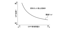
- FIG. 2 is a diagram showing the fuel cut prohibition region R.
- the fuel cut prohibition region R is preset according to the GPF soot deposit amount S and the GPF temperature T using map data.
- the fuel cut prohibition region R is defined as a region where the GPF temperature T is higher than the threshold Tref.
- the threshold Tref is a value for defining the fuel cut prohibition region R, and is set in advance according to the GPF soot deposition amount S. As the GPF soot accumulation amount S increases, the GPF becomes more likely to overheat due to soot combustion. Therefore, the threshold Tref is set to be smaller as the GPF soot deposition amount S is larger.
- the vehicle controller 30 comprehensively controls the engine 1, the generator 2, and the drive motor 3.
- the vehicle controller 30 includes an atmospheric pressure sensor 61 for detecting atmospheric pressure, an accelerator opening sensor 62 for detecting accelerator opening APO, a mode switch 63 for selecting a drive mode by driver operation, and a mode switch 63 for selecting a drive mode by driver operation.
- a signal from a shift position sensor 64 for detecting the shift position (range) is input.
- the vehicle controller 30 constitutes a controller 50 together with the motor controller 10 and the engine controller 20 .
- Fig. 3 is an explanatory diagram of shift positions and drive modes.
- Vehicle 100 further has a shifter 9 .
- the shifter 9 is a device for selecting a shift position by a driver's operation, and the driver's operation is performed by manipulating a shift lever or a switch to a gate corresponding to each shift position.
- the shifter 9 is a momentary shifter. In the momentary shifter 9, the shift lever released from the driver's operation autonomously returns to the home position, which is the neutral position.
- the shift positions selectable by the shifter 9 are P range (parking range), R range (reverse range), N range (neutral range), D range as the first forward range, and B range as the second forward range. including.
- the D range and B range are selected by operating the shift lever to the D/B gate common to these. By operating the shift lever to the D/B gate, the B range is selected when the D range is selected, and the D range is selected when the B range is selected. When a range other than the D range and the B range is selected, the D range is selected by operating the shift lever to the D/B gate.
- the drive modes selectable by the mode SW 63 include N mode, S mode and ECO mode.
- the N mode is a mode (normal mode) in which acceleration is performed by operating the accelerator pedal. Therefore, in the N mode, strong regenerative deceleration is not performed by operating the accelerator pedal.
- the S mode and the ECO mode are modes in which acceleration and regenerative deceleration are performed by operating the accelerator pedal (one-pedal mode), and the ECO mode is more suitable for fuel-efficient driving than the S mode.
- the drive mode is changed in the order of N mode, S mode and ECO mode each time the mode switch 63 is pressed, and returns to N mode after ECO mode.
- the drive motor 3 regenerates to generate deceleration. Deceleration is, in other words, negative acceleration and is indicated by a negative value.
- the regeneration limit amount magnitude of the regeneration limit
- the electric power obtained by regeneration is larger than that in the ECO mode, and the magnitude of deceleration generated is also larger.
- the ECO mode constitutes the first drive mode
- the S mode constitutes the second drive mode.
- deceleration can be obtained by regenerating the drive motor 3 during deceleration.
- Regeneration can be performed when there is room for regeneration in terms of the power balance of vehicle 100, that is, when there is a margin in the maximum acceptable power.
- the vehicle 100 is further configured as follows.
- FIG. 4 and 5 are block diagrams showing the processing of the vehicle controller 30.
- the vehicle controller 30 includes a target drive torque calculation unit 31, a target drive power calculation unit 32, a target power calculation unit 33, a GPF state determination unit 34, a retard discharge request determination unit 35, and an ENG operating point calculation unit 36. , an ENG operation mode determination unit 37 , an ENG power consumption calculation unit 38 , a regenerative torque limit calculation unit 39 , and a regenerative torque limit unit 40 .
- a target drive torque calculation unit 31 calculates a target drive torque TQ MOT — T of the drive motor 3 based on the accelerator opening APO and the vehicle speed VSP.
- the target drive torque TQMOT_T can be set in advance by map data according to the accelerator opening APO and the vehicle speed VSP.
- the target drive torque calculator 31 calculates a negative target drive torque TQ MOT _T during regeneration, that is, a target regenerative torque.
- the calculated target drive torque TQ MOT _T is input to the regenerative torque limiter 40 .
- the target drive power calculator 32 calculates a target drive power EP MOT _T of the drive motor 3 based on the target drive torque TQ MOT _T, the rotational speed N MOT of the drive motor 3, and the power consumption of the auxiliary machine.
- the target drive torque TQ MOT _T to which the limit in the regenerative torque limiter 40 described later is applied is input to the target drive power calculator 32 .
- the accessory power consumption is the power consumption of accessories that consume power, such as an air conditioner and an electric power steering device.
- the calculated target drive power EP MOT _T is input to the target power calculator 33 .
- the SOC control power request and other power generation/discharge requests are input to the target power calculation unit 33 .
- the SOC control power request is a power generation/discharge request corresponding to the SOC, and is performed when the battery 6 is fully charged and when the SOC is below a predetermined value, that is, when the battery 6 is low in charge. including demand for generation.
- Other power generation/discharge requests are power generation/discharge requests other than the SOC control power request. Including an upper limit power generation request (power generation stop request) for protecting parts related to the power generation of , and a discharge request for surplus regenerative power that is regenerative power for realizing deceleration due to regeneration and cannot be charged to the battery 6 .
- the target power calculator 33 calculates a target power EP ICE _T for power generation or discharge by the engine 1 based on the input.
- the target power calculation unit 33 prioritizes the various requests described above, arbitrates the power according to the various requests, and then reflects the power in the target driving power EP MOT _T.
- a target power EPICE_T is calculated.
- the calculated target power EP ICE _T is input to the ENG operating point calculator 36 and the ENG operation mode determiner 37 .
- the GPF state determination unit 34 determines the state of the GPF based on the GPF soot deposition amount S and the GPF temperature T.
- the map data shown in FIG. 2 is referred to in the GPF state determination unit 34, and it is determined whether or not the state of the GPF based on the GPF soot accumulation amount S and the GPF temperature T is included in the fuel cut prohibition region R.
- the GPF state determination unit 34 turns the GPF state flag ON (fuel cut prohibition request) when the state of the GPF is included in the fuel cut prohibition region R, that is, when the fuel cut prohibition condition is satisfied.
- the fuel cut prohibition condition is a condition determined based on the GPF temperature T, and is met when the GPF temperature T is higher than the threshold Tref.
- the GPF state determination unit 34 turns off the GPF state flag (fuel cut permitted) when the state of the GPF is not included in the fuel cut prohibition region R, that is, when the fuel cut prohibition condition is not satisfied.
- the GPF status flag is input from the GPF status determination section 34 to the retard discharge request determination section 35 .
- other power generation/discharge requests and SOC control power requests are input to the retard discharge request determination unit 35 .
- the retard discharge request determination unit 35 determines whether or not there is a retard discharge request based on the input.
- the retard discharge is an example of a power consumption operation in which the generator 2 drives the engine 1 to generate the negative ENG torque TQ ICE while the engine 1 performs combustion.
- the engine 1 and the generator 2 create a state of ENG torque TQ ICE ⁇ friction torque, so that the battery 6 is discharged while the engine 1 performs combustion.
- the ignition timing is retarded at this time, and the engine 1 performs combustion. In this case, the combustion slows down and the ENG torque TQ ICE decreases, so it is easy to create a state of ENG torque TQ ICE ⁇ friction torque.
- the retard discharge request determination unit 35 turns ON the retard discharge flag when there is a discharge request and the GPF state flag is ON (that is, when there is a fuel cut prohibition request).
- the GPF state flag is OFF (that is, when fuel cut is permitted)
- the retard discharge flag is turned OFF.
- the retard discharge flag is input from the retard discharge request determination unit 35 to the ENG operating point calculation unit 36 , the ENG operation mode determination unit 37 and the ENG power consumption calculation unit 38 .
- the vehicle speed VSP and the ENG oil temperature T OIL are further input to the ENG operating point calculation unit 36 .
- the ENG operating point calculator 36 calculates the target operating point of the engine 1 based on the input.
- the target operating point can be preset by map data according to the target power EPICE_T . If the target power EP ICE _T is positive, power will be generated. In this case, the target ENG torque TQ ICE _T is calculated as the target operating point in order to power-generate the engine 1 with the target ENG torque TQ ICE _T. If the target power EPICE_T is negative, motoring or retarding discharge will occur. A negative target power EPICE_T corresponds to a discharge request for discharging by motoring or retarded discharge.
- the target ENG rotation speed N ICE _T is calculated as the target operating point in order to drive the generator 2 at the target ENG rotation speed N ICE _T.
- Retard discharge is performed when the retard discharge flag is ON.
- the target ENG rotational speed N ICE _T and the target ENG torque TQ ICE _T are calculated as target operating points. This is because the engine 1 is operated at the target ENG torque TQ ICE _T, and the generator 2 is driven at the target ENG rotation speed N ICE _T to perform discharge.
- the target ENG rotation speed N ICE _T is set in advance according to the required discharge power, which is the negative target power EP ICE _T, as follows.
- FIG. 6 is a diagram showing map data of the target ENG rotation speed N ICE _T according to the required discharge power.
- FIG. 6 shows map data of the target ENG rotation speed N ICE — T during retard discharge.
- FIG. 6 shows the required discharge power as an absolute value.
- the map data for retard discharge is set based on the torque characteristics of the ENG torque TQ ICE that can be generated for each ENG rotational speed N ICE . Similar to general engine friction torque characteristics, the torque characteristics during retard discharge tend to increase the absolute value of ENG torque TQ ICE as the ENG rotation speed N ICE increases. proportional to TQ ICE . Therefore, the map data for retard discharge has a characteristic that the target ENG rotation speed N ICE _T increases as the absolute value of the required discharge power increases. In FIG. 6, the map data is set under the condition that the absolute value of the ENG torque TQ ICE during retard discharge is the smallest.
- the map data during retard discharge has such characteristics as a result of reflecting the power consumption characteristics during retard discharge, and the map data during retard discharge and the map data during motoring are separately prepared. Therefore, the ENG operating point calculation unit 36 calculates the target ENG rotational speed N ICE _T based on the power consumption characteristics during retard discharge by referring to the map data shown in FIG.
- the map data of the target ENG rotation speed N ICE_T is corrected according to the ENG oil temperature T OIL , and the lower the ENG oil temperature T OIL , the greater the friction of the engine 1 . Therefore, the lower the ENG oil temperature T OIL , the lower the target ENG rotational speed N ICE _T for the same required discharge power. Therefore, in the ENG operating point calculator 36, the lower the ENG oil temperature T OIL , the lower the target ENG rotational speed N ICE — T for the same required discharge power is corrected.
- the map data for retard discharge may be further set according to a parameter representing a factor of variation of the ENG torque TQ ICE such as the ENG oil temperature T OIL .
- a parameter representing a factor of variation of the ENG torque TQ ICE such as the ENG oil temperature T OIL .
- the target ENG rotation speed N ICE _T is further limited by the noise vibration upper limit rotation speed N ICE _L from the viewpoint of noise vibration.
- the noise vibration upper limit rotation speed N ICE _L is set in advance according to the vehicle speed VSP, and increases as the vehicle speed VSP increases.
- the target ENG rotation speed N ICE _T is the noise vibration upper limit rotation speed N ICE at the first vehicle speed VSP1. matches _L1.
- the target ENG rotation speed N ICE _T does not exceed the noise vibration upper limit rotation speed N ICE _L1, it is not limited by the noise vibration upper limit rotation speed N ICE _L1.
- the target ENG rotation speed N ICE _T is the noise vibration upper limit rotation speed N ICE at the second vehicle speed VSP2.
- the target ENG rotation speed N ICE _T to which the correction by the ENG oil temperature T OIL and the limit by the noise vibration upper limit rotation speed N ICE _L are applied is converted into the final target ENG rotation speed N ICE _T. Calculated as speed N ICE _T.
- the target ENG rotation speed N ICE — T calculated by the ENG operating point calculator 36 is input to the generator controller 12 .
- the generator controller 12 controls the generator 2 based on the inputted target ENG rotational speed N ICE _T. As a result, power consumption, ie, discharge, is performed by motoring the engine 1 and retard discharge.
- the generator controller 12 constitutes the motor controller 10 together with the drive motor controller 11 .
- the ENG operation mode determination unit 37 determines the operation mode of the engine 1 based on the input.
- the ENG operation mode determination unit 37 sets the ENG operation mode flag to retard discharge when the target power EPICE_T is negative and the retard discharge flag is ON.
- the ENG operation mode determination unit 37 sets the ENG operation mode flag to power generation operation when the target electric power EP ICE _T is positive, and sets the ENG operation when the target electric power EP ICE _T is negative and the retard discharge flag is OFF.
- the mode flag is set to motoring.
- Permission output power POUT is power that can be output by battery 6, and the ENG operation mode flag is set to retard discharge when permission output power POUT is greater than predetermined value POUT1.
- the predetermined value POUT1 is a value for preventing the battery 6 from being over-discharged due to factors other than the SOC, such as environmental factors, and is set in advance. Even if the SOC is greater than the SOC for requesting power generation, the permitted output power POUT becomes small, for example, when the temperature of the battery 6 is extremely high or extremely low.
- the operation mode flag of the engine 1 can be set to power generation operation.
- the ENG operation mode flag is input from the ENG operation mode determination section 37 to the engine controller 20 .
- the target ENG torque TQ ICE _T calculated by the ENG operating point calculator 36 is also input to the engine controller 20 .
- the engine controller 20 controls the engine 1 based on the input target ENG torque TQICE_T and the ENG operation mode flag. As a result, the generator 2 is driven by the engine 1 when generating power. Further, when retarded discharge is performed, combustion is performed in the engine 1 with the ignition timing retarded.
- the ENG operation mode flag is set to retard discharge when the permitted output power POUT is greater than the predetermined value POUT1. Therefore, when the permitted output power POUT is greater than the predetermined value POUT1, even if there is an ISC (idle speed control) request of the engine 1, retard discharge is performed prior to the ISC request.
- the ENG power consumption calculation unit 38 receives the ENG operation mode flag set by the ENG operation mode determination unit 37, the ENG rotational speed N ICE , the ENG oil temperature T OIL and the vehicle speed VSP.
- the ENG power consumption calculation unit 38 calculates ENG power consumption obtained by motoring or retard discharge.
- the ENG power consumption is the power consumption of the power generation unit consisting of the engine 1 and the generator 2 .
- the calculated ENG power consumption is a calculated value of power consumption obtained by retarded discharge or motoring, and corresponds to an estimated power consumption value.
- the ENG power consumption is calculated based on the ENG rotational speed NICE .
- the ENG power consumption is negative, and the higher the ENG rotation speed NICE , the larger the absolute value calculated.
- the ENG power consumption is preset by map data according to the ENG rotational speed NICE . Map data to be referred to during motoring and map data to be referred to during retard discharge are prepared separately.
- the map data of the ENG power consumption during retard discharge is obtained by replacing the target ENG rotation speed N ICE _T with the ENG rotation speed N ICE in the map data shown in FIG. 6 and replacing the required discharge power with the ENG power consumption. Therefore, in the ENG power consumption calculator 38, the ENG power consumption is calculated based on the power consumption characteristics during retard discharge corresponding to the ENG rotation speed NICE by referring to the map data of the ENG power consumption during retard discharge. . Further, the ENG power consumption is corrected based on the ENG oil temperature TOIL , and the corrected ENG power consumption is calculated as the final ENG power consumption. For the same ENG rotation speed NICE , the ENG power consumption is corrected in a larger absolute value as the ENG oil temperature T- OIL is lower.
- the ENG power consumption calculator 38 gradually changes the ENG power consumption from ENG power consumption obtained by retard discharge to ENG power consumption obtained by motoring.
- the ENG power consumption steadily obtained by motoring is larger in absolute value than the ENG power consumption steadily obtained by retard discharge. Therefore, the ENG power consumption calculator 38 gradually increases the ENG power consumption in terms of absolute value during the transition.
- the ENG power consumption calculator 38 further changes the power change rate according to the vehicle speed VSP during the transition as described below.
- FIG. 7 is a diagram showing the power change rate according to the vehicle speed VSP.
- the power change rate is the change rate of the ENG power consumption at the time of transition from retard discharge to motoring, and the higher the vehicle speed VSP, the greater the power change rate. As a result, the higher the vehicle speed VSP, the faster the transition from retard discharge to motoring.
- the auxiliary machine power consumption and the permitted input power PIN are input to the regenerative torque limit calculation section 39 .
- the allowable input power PIN is the power that can be input to the battery 6 and is zero or has a negative value.
- Regenerative torque limit calculation unit 39 calculates regenerative possible torque TQ MOT _L of drive motor 3 based on the sum of ENG power consumption, accessory power consumption, and permitted input power PIN.
- System regenerated maximum electric power PMAX is the maximum electric power that can be regenerated by vehicle 100 in terms of absolute value, and indicates the maximum electric power that can be accepted by vehicle 100 .
- regenerative torque limit calculation unit 39 regenerative torque corresponding to the system regenerative maximum electric power PMAX is calculated as regenerative possible torque TQMOT_L .
- Regeneration cannot be performed with a driving torque Q MOT that is larger in absolute value than the regenerative torque TQ MOT _L. Therefore, in other words, the regenerative possible torque can be said to be the regenerative limited torque.
- the calculated regenerative possible torque TQ MOT _L is input to the regenerative torque limiter 40 .
- the regenerative torque limiter 40 limits the target drive torque TQ MOT _T of the drive motor 3 by the input regenerative possible torque TQ MOT _L.
- the target driving torque TQ MOT_T represents the target regenerative torque when negative.
- the negative target driving torque TQ MOT _T is limited to the regenerative possible torque TQ MOT _L when it becomes equal to or less than the regenerative possible torque TQ MOT _L.
- the target driving torque TQMOT_T is limited by the torque TQMOT_Lr that can be regenerated during retard discharge, so that the regenerative torque is limited according to the ENG power consumption due to retard discharge.
- the target drive torque TQ MOT _T to which the limit has been applied is input to the drive motor controller 11 as the final target drive torque TQ MOT _T, and the drive motor controller 11 drives based on the input target drive torque TQ MOT _T. Drive the motor 3. If the target driving torque TQ MOT_T is negative, regeneration is performed.
- the target drive torque TQ MOT _T to which the limit has been applied is also input to the target drive power calculator 32 .
- FIG. 8 shows an example of discharge control performed by the controller 50 in a flowchart.
- FIG. 8 shows the case where the drive mode is the S mode.
- the controller 50 functionally implements a control section by performing the processing of the flowchart shown in FIG.
- the processing of the flowchart shown in FIG. 8 can be repeatedly executed.
- the controller 50 determines whether the target power EPICE_T is less than zero. If the determination in step S1 is affirmative, it is determined that there is a discharge request because the target power EP ICE _T is the target discharge power.
- the discharge request is a discharge request for causing the generator 2 to discharge, and the generator 2 discharges by driving the engine 1 based on such a discharge request.
- the target power EP ICE _T becomes negative, for example, when the target drive power EP MOT _T is negative and there is no power generation request or discharge prohibition request with a higher priority than the target drive power EP MOT _T. Therefore, when there is a discharge request, it is during regeneration including the start of regeneration, for example.
- the case where the target power EPICE_T is less than zero includes the case where the battery 6 is fully charged.
- negative power is added to the negative target drive power EP MOT _T as power corresponding to the SOC control power request, resulting in the target power EP ICE _T becoming less than zero. If the determination in step S1 is affirmative, the process proceeds to step S2.
- step S2 the controller 50 determines whether the GPF temperature T is higher than the threshold Tref. That is, it is determined whether or not the fuel cut prohibition condition is satisfied. If the determination in step S2 is affirmative, the GPF state flag is turned ON, and the controller 50 prohibits fuel cut in step S3.
- step S4 the controller 50 determines whether or not the allowable output power POUT of the battery 6 is greater than a predetermined value POUT1. In the case of a negative determination in step S4, the process is temporarily terminated. In this case, it is determined that the battery 6 is in an over-discharged state, so the engine 1 can be operated to generate electricity. If the determination in step S4 is affirmative, it is determined that the battery 6 is not in an over-discharged state, and the process proceeds to step S5.
- step S5 the controller 50 executes retard discharge.
- the battery 6 can be discharged while suppressing overheating of the GPF, thereby increasing the room for regeneration. Therefore, even when fuel cut is prohibited and the battery 6 is fully charged, deceleration can be obtained by regeneration.
- step S2 the GPF state flag is OFF, and the controller 50 executes fuel cut of the engine 1 in step S6 and motoring in step S7. That is, in this case, since the GPF does not overheat even if motoring is performed, the battery 6 is discharged by the motoring. In this case, since regeneration can be performed in accordance with the amount of discharge due to motoring, a larger absolute deceleration is ensured than in the case of retarded discharge.
- step S7 the transition from retard discharge to motoring is started in step S7.
- the controller 50 gradually changes the ENG power consumption.
- the controller 50 gradually changes the ENG power consumption from the ENG power consumption obtained by retard discharge to the ENG power consumption obtained by motoring.
- the gradual change in ENG power consumption continues until the ENG power consumption reaches the ENG power consumption obtained by motoring.
- step S7 the process is temporarily terminated.
- step S1 If the determination in step S1 is negative, there will be no discharge request. Therefore, retard discharge and motoring are stopped. If the determination in step S1 is negative, it is determined in step S8 whether or not the GPF temperature T is higher than the threshold value Tref. Then, if the determination in step S8 is affirmative, fuel cut is prohibited in step S9. In this case, the power generation operation of the engine 1 can be performed. If the determination in step S8 is negative, the process is temporarily terminated. In this case, the GPF state flag is OFF and the fuel cut is permitted, so the power generation operation and operation stop of the engine 1 can be performed.
- step S1 to step S4, step S8, and step S9 can be performed by the vehicle controller 30.
- the process of step S5 can be performed by the motor controller 10 and the engine controller 20.
- FIG. The process of step S6 can be performed by the engine controller 20, and the process of step S7 can be performed by the motor controller 10.
- FIG. 9 is a diagram showing a first example of a timing chart corresponding to FIG. FIG. 9 shows a case where retard discharge is performed.
- the vehicle 100 Before the timing T1, the vehicle 100 is traveling uphill at a constant vehicle speed VSP.
- the accelerator opening APO is greater than zero, and the target drive torque TQ MOT _T of the drive motor 3 and the target drive power EP MOT _T corresponding to the target drive torque TQ MOT _T are positive.
- the GPF state flag is ON, and the operating state of the engine 1 is positive torque operation in which positive torque is generated by combustion. Therefore, the actual ENG torque TQ ICE _A of the engine 1 is positive, and the actual GEN torque TQ GEN _A of the generator 2 is negative.
- the GEN rotational speed N GEN of the generator 2 is greater than zero.
- the constant accelerator opening APO starts to decrease, and accordingly the target drive torque TQ MOT _T and the target drive power EP MOT _T also start to decrease.
- the accelerator opening APO becomes zero before the timing T1, and the target driving torque TQ MOT _T becomes negative accordingly, so that the target driving power EP MOT _T becomes negative at the timing T1.
- the regenerative torque TQ MOT_L and the system regenerative maximum power PMAX decrease (increase in absolute value) by the amount of retard discharge. Since the target driving torque TQ MOT _T is limited by the regenerative possible torque TQ MOT _L, it decreases to the regenerative possible torque TQ MOT _L.
- the target drive power EP MOT_T decreases to the system regenerated maximum power PMAX. As a result, the amount of regeneration increases by the amount of discharge due to retard discharge.
- FIG. 10 is a diagram showing a second example of a timing chart corresponding to FIG. FIG. 10 shows a case where motoring is performed.
- the state before timing T11 is the same as in FIG. 9 except that the GPF state flag is OFF.
- a discharge request is issued in a state where fuel cut is not prohibited.
- motoring is started in response to this, and the operating state of the engine 1 becomes fuel cut, that is, the operation is stopped.
- the engine 1 in the stopped state is driven by the power generator 2, so that more electric power is consumed than in retard discharge. Therefore, the discharge power of the generator 2 indicated by hatching is larger than that in FIG. 9, and the regenerative torque TQ MOT_L and system regenerative maximum power PMAX are also larger than those in FIG. 9 in terms of absolute values.
- the target driving torque TQ MOT _T and the target driving power EP MOT _T also become larger in absolute value than in the case of FIG. 9, including the case where the allowable input power PIN becomes zero at the timing T13. Therefore, a deceleration larger in absolute value than in the case of retard discharge is ensured.
- FIG. 11 is a diagram showing a third example of a timing chart corresponding to FIG. FIG. 11 shows the transition from retarded discharge to motoring.
- fuel cut of the engine 1 is prohibited, and retard discharge is performed as negative torque operation.
- the generator 2 drives the engine 1 in which combustion is being performed. Therefore, the GEN torque TQ GEN of the generator 2 is greater than zero.
- the vehicle 100 is traveling downhill at a constant vehicle speed VSP, and is performing regeneration. Therefore, the accelerator opening APO is zero, and the target drive torque TQ MOT _T and the target drive power EP MOT _T are negative.
- the target drive torque TQ MOT _T is limited to the regenerative torque TQ MOT _L.
- the GPF status flag changes from ON to OFF.
- fuel cut of the engine 1 is performed and motoring is started.
- the result is a transition from retarded discharge to motoring.
- the target driving torque TQ MOT _T and the target driving power EP MOT _T decrease and increase in absolute value, so the GEN torque TQ GEN also increases.
- the ENG power consumption is gradually changed from the ENG power consumption obtained by retard discharge to the ENG power consumption obtained by motoring.
- the regenerative possible torque TQ MOT _L gradually decreases, and as a result, the target driving torque TQ MOT _T gradually decreases while being limited to the regenerative possible torque TQ MOT _L.
- the maximum potential deceleration that is possible by motoring can be obtained while suppressing the driver from feeling uncomfortable.
- the rotation speed is controlled by the generator 2 coupled with the engine 1 . Therefore, even if the running engine 1 runs out of fuel during retard discharge, the generator 2 maintains the GEN rotation speed N GEN , and as a result, the engine 1 enters a motoring state and the GPF can overheat.
- the vehicle controller 30 is further configured as described below.
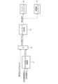
- FIG. 12 is a block diagram showing the processing of gas shortage response control.
- the vehicle controller 30 includes a gas shortage determination torque calculation section 41 , a gas shortage determination section 42 and an engine mode determination section 43 .
- the ENG rotation speed N ICE and the ENG oil temperature T OIL are input to the gas shortage determination torque calculation unit 41 .
- a gas shortage determination torque calculation unit 41 calculates a gas shortage determination torque TQ GEN_D .
- the gas shortage determination torque TQ GEN_D is a gas shortage determination threshold for determining gas shortage, and is set in advance according to the ENG rotation speed N ICE and the ENG oil temperature T OIL .
- FIG. 13 is a diagram showing an example of map data of the gas shortage determination torque TQ GEN_D .
- the gas shortage determination torque TQ GEN_D is set larger as the ENG rotation speed N ICE is higher. Furthermore, the higher the ENG oil temperature T OIL , the greater the gas shortage determination torque TQ GEN _D is set at the same ENG rotation speed N ICE . Since the GPF temperature T is higher than the threshold Tref while the fuel cut is prohibited, the engine 1 is already warmed up. This includes the cold start of the engine 1 when fuel cut is not prohibited. Therefore, by changing the gas shortage determination torque TQ GEN_D according to the ENG oil temperature T OIL , it is possible to appropriately perform the gas shortage determination both when the fuel cut is prohibited and when the fuel cut is not prohibited.
- the calculated gas shortage determination torque TQ GEN _D is input from the gas shortage determination torque calculation unit 41 to the gas shortage determination unit 42 .
- the actual GEN torque TQ GEN _A of the generator 2 is also input to the gas shortage determination unit 42 .
- the gas shortage determination unit 42 determines that the engine 1 is out of gas when the actual GEN torque TQ GEN_A is greater than the gas shortage determination torque TQ GEN_D . As a result, it is detected that the engine 1 is not injecting fuel.
- the gas shortage determination unit 42 turns ON the gas shortage determination flag when it determines that the gas shortage has occurred, and turns the gas shortage determination flag OFF when it determines that the gas shortage has not occurred.
- the gas shortage determination flag is input from the gas shortage determination unit 42 to the engine mode determination unit 43 .
- the engine mode determination unit 43 determines the operating mode of the engine 1. Operation modes include power generation operation, motoring, retard discharge, and shutdown.
- the engine mode determination unit 43 generates a stop command when the operation mode is retarded discharge.
- a stop command can be generated when the engine 1 is in a negative torque operation with fuel cut prohibited.
- a stop command is input from the engine mode determination unit 43 to the engine controller 20 and the generator controller 12 .
- the engine controller 20 stops the operation of the engine 1 based on the input stop command, and the generator controller 12 stops driving the generator 2 based on the input stop command. As a result, retard discharge is stopped.
- FIG. 14 is a flowchart showing an example of the out-of-gas control performed by the controller 50. As shown in FIG. The processing of this flowchart can be performed when retard discharge is being performed.
- the controller 50 determines whether or not the gas shortage determination torque TQ GEN_D is greater than or equal to the actual GEN torque TQ GEN_A . If the determination in step S11 is affirmative, the actual GEN torque TQ GEN_A is less than the gas shortage determination torque TQ GEN_D , so it is determined that gas shortage has not occurred. In this case, retard discharge is continued in step S12. After step S12, the process is temporarily terminated.
- step S11 If the determination in step S11 is negative, the actual GEN torque TQ GEN_A is greater than the gas shortage determination torque TQGEN_D, so it is determined that gas shortage has occurred. Thus, it is detected that the gas is running out from the actual GEN torque TQ GEN_A . If the determination in step S11 is negative, the process proceeds to step S13.
- step S13 the controller 50 stops the operation of the engine 1 and the generator 2, thereby stopping the power generation/discharge operation.
- the generator 2 which is trying to maintain the rotational speed by the rotational speed control, from driving the engine 1 which is out of gas despite the fuel cut prohibition state.
- the GPF can be protected by preventing overheating of the GPF due to oxygen supply.
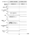
- FIG. 15 is a diagram showing an example of a timing chart corresponding to FIG. 14.
- the GPF flag is ON, the operating state of the engine 1 is in the combustion/negative torque operating state, and retard discharge is being performed. Therefore, the GEN rotation speed N GEN and the actual GEN torque TQ GEN_A of the generator 2 are positive.
- the vehicle 100 is traveling downhill at a constant vehicle speed VSP, and is performing regeneration. Therefore, the accelerator opening APO is zero, and the target drive torque TQ MOT _T and the target drive power EP MOT _T of the drive motor 3 are negative. Since retard discharge is being performed, the remaining fuel is gradually decreasing.
- the generator 2 tries to maintain the GEN rotation speed N GEN .
- the actual GEN torque TQ GEN _A of the generator 2 begins to rise, and exceeds the out-of-gas determination torque TQ GEN _D at timing T32. Therefore, in response to this, the operation of the engine 1 and the driving of the generator 2 are stopped at timing T33.
- the target driving torque TQ MOT _T and the target driving power EP MOT _T increase to zero, while the GEN rotational speed N GEN and the actual GEN torque TQGEN_A decrease to zero. This prevents the generator 2 trying to maintain the GEN rotation speed N GEN in the fuel cut prohibited state from driving the engine 1 in the gas shortage state, thereby preventing overheating of the GPF.
- an engine 1, a generator 2, and a drive motor 3 are provided.
- the actual GEN torque TQ GEN_A of the generator 2 indicates that the retard discharge is performed and that the engine 1 is not injecting fuel while the fuel cut of the engine 1 is prohibited. and stopping the generator 2 when it is detected that gas shortage has occurred.
- the oxygen sensor has an activation temperature, and the oxygen sensor cannot be used until the temperature of the oxygen sensor reaches the activation temperature.
- the actual GEN torque TQ GEN _A of the generator 2 is greater than the out-of-gas determination torque TQ GEN _D of the engine 1, it is determined that the engine 1 is not injecting fuel.
- the gas shortage determination torque TQ GEN_D is changed according to the ENG oil temperature T OIL of the engine 1, and even when the fuel cut of the engine 1 is not prohibited, the occurrence of the gas shortage is detected by the generator. 2 actual GEN torque TQ GEN_A .
- the engine 1 since the out-of-gas determination torque TQ GEN_D is changed according to the ENG oil temperature T OIL , the engine 1 can be appropriately controlled even when the fuel cut is not prohibited, including when the engine 1 is cold-started. Gas shortage determination can be performed. In addition, even when the fuel cut is not prohibited, including when the engine 1 is cold-started, the actual GEN torque TQ GEN_A is used to detect that the gas has run out. judgment time can be shortened.
- the power consumption operation may be a negative torque operation in which the generator 2 drives the engine 1 during idling to generate negative torque in the engine 1 .
Abstract
Priority Applications (3)
| Application Number | Priority Date | Filing Date | Title |
|---|---|---|---|
| JP2023546604A JPWO2023037421A1 (fr) | 2021-09-07 | 2021-09-07 | |
| CN202180101977.0A CN117881586A (zh) | 2021-09-07 | 2021-09-07 | 车辆的控制方法以及车辆 |
| PCT/JP2021/032916 WO2023037421A1 (fr) | 2021-09-07 | 2021-09-07 | Procédé de commande de véhicule et véhicule |
Applications Claiming Priority (1)
| Application Number | Priority Date | Filing Date | Title |
|---|---|---|---|
| PCT/JP2021/032916 WO2023037421A1 (fr) | 2021-09-07 | 2021-09-07 | Procédé de commande de véhicule et véhicule |
Publications (1)
| Publication Number | Publication Date |
|---|---|
| WO2023037421A1 true WO2023037421A1 (fr) | 2023-03-16 |
Family
ID=85507311
Family Applications (1)
| Application Number | Title | Priority Date | Filing Date |
|---|---|---|---|
| PCT/JP2021/032916 WO2023037421A1 (fr) | 2021-09-07 | 2021-09-07 | Procédé de commande de véhicule et véhicule |
Country Status (3)
| Country | Link |
|---|---|
| JP (1) | JPWO2023037421A1 (fr) |
| CN (1) | CN117881586A (fr) |
| WO (1) | WO2023037421A1 (fr) |
Citations (4)
| Publication number | Priority date | Publication date | Assignee | Title |
|---|---|---|---|---|
| WO2011074074A1 (fr) * | 2009-12-15 | 2011-06-23 | トヨタ自動車株式会社 | Véhicule électrique |
| JP2018065448A (ja) | 2016-10-19 | 2018-04-26 | トヨタ自動車株式会社 | ハイブリッド自動車 |
| JP2018177184A (ja) * | 2017-04-10 | 2018-11-15 | トヨタ自動車株式会社 | ハイブリッド自動車 |
| JP2020111164A (ja) * | 2019-01-11 | 2020-07-27 | トヨタ自動車株式会社 | ハイブリッド自動車 |
-
2021
- 2021-09-07 CN CN202180101977.0A patent/CN117881586A/zh active Pending
- 2021-09-07 JP JP2023546604A patent/JPWO2023037421A1/ja active Pending
- 2021-09-07 WO PCT/JP2021/032916 patent/WO2023037421A1/fr active Application Filing
Patent Citations (4)
| Publication number | Priority date | Publication date | Assignee | Title |
|---|---|---|---|---|
| WO2011074074A1 (fr) * | 2009-12-15 | 2011-06-23 | トヨタ自動車株式会社 | Véhicule électrique |
| JP2018065448A (ja) | 2016-10-19 | 2018-04-26 | トヨタ自動車株式会社 | ハイブリッド自動車 |
| JP2018177184A (ja) * | 2017-04-10 | 2018-11-15 | トヨタ自動車株式会社 | ハイブリッド自動車 |
| JP2020111164A (ja) * | 2019-01-11 | 2020-07-27 | トヨタ自動車株式会社 | ハイブリッド自動車 |
Also Published As
| Publication number | Publication date |
|---|---|
| JPWO2023037421A1 (fr) | 2023-03-16 |
| CN117881586A (zh) | 2024-04-12 |
Similar Documents
| Publication | Publication Date | Title |
|---|---|---|
| US7967091B2 (en) | Hybrid electric vehicle powertrain with engine start and transmission shift arbitration | |
| EP3725615B1 (fr) | Procédé et dispositif pour commander un véhicule hybride | |
| US20090227409A1 (en) | Control device and control method for vehicle | |
| JP5338351B2 (ja) | ハイブリッド車両の制御装置 | |
| US6262491B1 (en) | Control system for hybrid vehicle | |
| WO2007080729A1 (fr) | Véhicule hybride et procédé de commande de celui-ci | |
| JP2011239605A (ja) | 車両の制御装置 | |
| JP6927328B2 (ja) | ハイブリッド車両の制御方法、及び、制御装置 | |
| JP2008094238A (ja) | ハイブリッド車の制御装置 | |
| JP3841052B2 (ja) | ハイブリッド車両の制御装置 | |
| JP2020104668A (ja) | 車両の制御装置 | |
| JP3594010B2 (ja) | 車両の駆動力制御方法とその制御装置 | |
| JP3891130B2 (ja) | 車両の減速制御装置 | |
| WO2023037421A1 (fr) | Procédé de commande de véhicule et véhicule | |
| JP2004270512A (ja) | ハイブリッド車両の制御装置 | |
| JP3714417B2 (ja) | ハイブリッド車両の制御装置 | |
| WO2023037420A1 (fr) | Procédé de commande de véhicule et véhicule | |
| JP5741068B2 (ja) | 電動車両 | |
| WO2023037419A1 (fr) | Procédé de commande de véhicule et véhicule | |
| JP2004211575A (ja) | 車輌の制御装置 | |
| JP2004034844A (ja) | 車両のトルク制御装置及びトルク制御方法 | |
| JP2000297668A (ja) | 車両のエンジン制御装置 | |
| EP4005888B1 (fr) | Procédé de commande de véhicule hybride et dispositif de commande de véhicule hybride | |
| JP2019025986A (ja) | ハイブリッド車両 | |
| WO2023095281A1 (fr) | Procédé de commande pour véhicule et dispositif de commande pour véhicule |
Legal Events
| Date | Code | Title | Description |
|---|---|---|---|
| 121 | Ep: the epo has been informed by wipo that ep was designated in this application |
Ref document number: 21956718 Country of ref document: EP Kind code of ref document: A1 |
|
| WWE | Wipo information: entry into national phase |
Ref document number: 2023546604 Country of ref document: JP |
|
| REG | Reference to national code |
Ref country code: BR Ref legal event code: B01A Ref document number: 112024003876 Country of ref document: BR |
|
| WWE | Wipo information: entry into national phase |
Ref document number: 2021956718 Country of ref document: EP |
|
| NENP | Non-entry into the national phase |
Ref country code: DE |
|
| ENP | Entry into the national phase |
Ref document number: 2021956718 Country of ref document: EP Effective date: 20240408 |