WO2023037409A1 - Dispositif de commande de mise à niveau, équipement de laminage muni de celui-ci, et procédé de commande de mise à niveau - Google Patents
Dispositif de commande de mise à niveau, équipement de laminage muni de celui-ci, et procédé de commande de mise à niveau Download PDFInfo
- Publication number
- WO2023037409A1 WO2023037409A1 PCT/JP2021/032839 JP2021032839W WO2023037409A1 WO 2023037409 A1 WO2023037409 A1 WO 2023037409A1 JP 2021032839 W JP2021032839 W JP 2021032839W WO 2023037409 A1 WO2023037409 A1 WO 2023037409A1
- Authority
- WO
- WIPO (PCT)
- Prior art keywords
- leveling
- stand
- rolling
- amount
- control device
- Prior art date
Links
- 238000005096 rolling process Methods 0.000 title claims abstract description 128
- 238000000034 method Methods 0.000 title claims description 39
- 229910000831 Steel Inorganic materials 0.000 claims abstract description 82
- 239000010959 steel Substances 0.000 claims abstract description 82
- 238000012937 correction Methods 0.000 claims abstract description 68
- 238000011144 upstream manufacturing Methods 0.000 claims abstract description 24
- 238000005098 hot rolling Methods 0.000 claims description 6
- 238000012545 processing Methods 0.000 description 12
- 238000004891 communication Methods 0.000 description 11
- 238000005452 bending Methods 0.000 description 8
- 230000000694 effects Effects 0.000 description 6
- 230000000875 corresponding effect Effects 0.000 description 5
- 238000010586 diagram Methods 0.000 description 5
- 239000000463 material Substances 0.000 description 3
- 238000005259 measurement Methods 0.000 description 3
- 238000012546 transfer Methods 0.000 description 3
- 239000000470 constituent Substances 0.000 description 2
- 230000001276 controlling effect Effects 0.000 description 2
- 230000002596 correlated effect Effects 0.000 description 2
- 238000001514 detection method Methods 0.000 description 2
- 230000000644 propagated effect Effects 0.000 description 2
- 238000007796 conventional method Methods 0.000 description 1
- 238000011161 development Methods 0.000 description 1
- 230000001771 impaired effect Effects 0.000 description 1
- 239000007769 metal material Substances 0.000 description 1
- 238000012986 modification Methods 0.000 description 1
- 230000004048 modification Effects 0.000 description 1
- 239000003607 modifier Substances 0.000 description 1
Images


Classifications
-
- B—PERFORMING OPERATIONS; TRANSPORTING
- B21—MECHANICAL METAL-WORKING WITHOUT ESSENTIALLY REMOVING MATERIAL; PUNCHING METAL
- B21B—ROLLING OF METAL
- B21B37/00—Control devices or methods specially adapted for metal-rolling mills or the work produced thereby
- B21B37/58—Roll-force control; Roll-gap control
Definitions
- the present invention relates to a leveling control device, a rolling facility equipped with the same, and a leveling control method.
- Patent Document 1 discloses that a strip is sequentially passed through a plurality of rolling mill stands arranged in series, and the strip is simultaneously rolled at each rolling mill stand.
- a method of controlling plate bending in a tandem mill that adjusts the amount of lateral reduction of each rolling mill stand based on the detected value of the tension deviation to remove the lateral tension deviation of the strip between each rolling mill stand, thereby controlling plate bending , adjustment of the reduction amount of the rolling mill stand is performed on the front side of the detection position based on the detected value of the lateral tension deviation of the strip coming out of the rolling mill stand, and this adjustment operation is sequentially performed toward the rolling mill stand on the entry side. It is stated that it will proceed.
- Patent Document 1 discloses that, based on the left and right tension deviation of the strip between each rolling mill stand, roll-down control is performed at the stand on the front side of the tension detection position, and this control is sequentially advanced to the entry side.
- the present invention provides a leveling control device that can improve the accuracy of roll reduction control of each stand of a hot rolling line in which a plurality of rolling stands are arranged compared to the conventional one, rolling equipment equipped with the same, and leveling control provide a way.
- the present invention includes a plurality of means for solving the above problems.
- One example is a leveling control device for a hot rolling line in which a plurality of rolling stands are arranged, wherein the leveling control device between the plurality of rolling stands From the results measured by each shape meter provided in, a torque acquisition unit that obtains the torque distribution applied in the width direction of the steel plate between each of the plurality of rolling stands, and the width direction from the obtained torque distribution a primary component calculation unit that obtains a tension distribution and obtains a primary component when the tension distribution of the steel sheet is represented by a polynomial from the tension distribution; and based on the obtained primary component, the plurality of rolling stands.
- a leveling correction amount calculation unit that obtains the leveling correction amount of the rolling stand immediately before the upstream side of the rolling, and based on the obtained leveling correction amount, the stand of the (last -1) stage among the plurality of rolling stands and a leveling amount changing unit that changes the leveling amount in order from the upstream side of the rolling.
- FIG. 5 is a diagram showing an example of a determination method within the allowable range of the primary component in the leveling control device of the first embodiment; 4 is a flowchart showing an example of the flow of leveling amount correction control in the leveling control device of the first embodiment; Schematic which shows the structure of the rolling equipment provided with the leveling control apparatus of Example 2 of this invention. 9 is a flow chart showing an example of the flow of leveling amount correction control in the leveling control device of the second embodiment. Schematic which shows the structure of the rolling equipment provided with the leveling control apparatus of Example 3 of this invention. 10 is a flow chart showing an example of the flow of leveling amount correction control in the leveling control device of the third embodiment.
- the material to be rolled in the present invention is not limited to a steel plate, but can be a strip of a metal material that can be rolled in general, and the type is not particularly limited. Non-ferrous materials can be targeted.
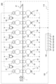
- FIG. 1 is a schematic diagram showing the structure of a rolling facility equipped with a leveling control device according to the first embodiment.
- a rolling facility 200 shown in FIG. 1 is a finish rolling facility for rolling a steel plate 1, and includes an F1 stand 10, an F2 stand 20, an F3 stand 30, an F4 stand 40, an F5 stand 50, an F6 stand 60, and an F7 stand 70. , cameras 81, 82, 83, 84, 85, 86, shape meters 91, 92, 93, 94, 95, 96, 97, a leveling control device 150, and the like.
- the rolling facility 200 is not limited to the configuration in which seven rolling stands are provided as shown in FIG. 1, and may have at least three stands.
- Each of the F1 stand 10, the F2 stand 20, the F3 stand 30, the F4 stand 40, the F5 stand 50, the F6 stand 60, and the F7 stand 70 has an upper work roll and a lower work roll, and the upper work roll and the lower work roll, respectively.
- Information on the rolling load measured by the load detectors 12 , 22 , 32 , 42 , 52 , 62 , 72 is transmitted to the leveling controller 150 via the communication line 110 .
- a six-stage configuration may be employed in which upper and lower intermediate rolls are further provided between each of the upper and lower work rolls and each of the upper and lower backup rolls.
- the roll configuration of the rolling mill is not limited to the form described above, and it is sufficient that there are at least upper and lower work rolls.
- Shape meters 91, 92, 93, 94, 95, and 96 are provided between F1 stand 10, F2 stand 20, F3 stand 30, F4 stand 40, F5 stand 50, F6 stand 60, and F7 stand 70, respectively. , is a measuring instrument for measuring the torque of the steel plate 1 . Moreover, the tension distribution in the width direction of the sheet can be detected, and the position of the steel sheet 1 can also be detected.
- Information on the surface shape of the steel plate 1 at the F1 stand 10 exit side (F2 stand 20 entry side) measured by the shape meter 91 is transmitted to the leveling control device 150 via the communication line 110 .
- Information on the surface shape of the steel plate 1 at the exit side of the F2 stand 20 (the entrance side of the F3 stand 30) measured by the shape meter 92 is transmitted to the leveling control device 150 via the communication line 110 .
- Information on the surface shape of the steel plate 1 at the F3 stand 30 exit side (F4 stand 40 entry side) measured by the shape meter 93 is transmitted to the leveling control device 150 via the communication line 110 .
- Information on the surface shape of the steel plate 1 at the F4 stand 40 exit side (F5 stand 50 entry side) measured by the shape meter 94 is transmitted to the leveling control device 150 via the communication line 110 .
- Information on the surface shape of the steel plate 1 at the F5 stand 50 exit side (F6 stand 60 entry side) measured by the shape meter 95 is transmitted to the leveling control device 150 via the communication line 110 .
- Information on the surface shape of the steel plate 1 at the exit side of the F6 stand 60 (the entrance side of the F7 stand 70) measured by the shape meter 96 is transmitted to the leveling control device 150 via the communication line 110 .
- the shape meter 97 is also a measuring instrument for measuring the surface shape of the steel plate 1, like the shape meter 91 and the like, and is provided on the exit side of the F7 stand 70. Information on the surface shape of the steel plate 1 on the delivery side of the F7 stand 70 measured by the shape meter 97 is transmitted to the leveling control device 150 via the communication line 110 .
- the camera 81 is provided at a position capable of capturing an image including the steel plate 1 on the exit side of the F1 stand 10 and the entry side of the F2 stand 20.
- the camera 82 is provided at a position capable of capturing an image including the steel plate 1 on the exit side of the F2 stand 20 and the entrance side of the F3 stand 30 .
- the camera 83 is provided at a position capable of capturing an image including the steel plate 1 on the exit side of the F3 stand 30 and the entrance side of the F4 stand 40 .
- the camera 84 is provided at a position capable of capturing an image including the steel plate 1 on the exit side of the F4 stand 40 and the entrance side of the F5 stand 50 .
- the camera 85 is provided at a position capable of capturing an image including the steel plate 1 on the exit side of the F5 stand 50 and the entry side of the F6 stand 60 .
- the camera 86 is provided at a position capable of capturing an image including the steel plate 1 on the delivery side of the F6 stand 60 and the entry side of the F7 stand 70 .
- These cameras 81 , 82 , 83 , 84 , 85 , 86 capture images including the steel plate 1 directly above or obliquely above the steel plate 1 at intervals of, for example, less than 0.1 seconds, preferably in the form of moving images.
- the data of the captured image is transmitted to the leveling control device 150 via the communication line 110 .
- the leveling control device 150 is a device configured by a computer or the like that controls the operation of each device in the rolling mill 200, and includes a torque acquisition unit 161, a primary component calculation unit 162, a leveling correction amount calculation unit 163, and a leveling amount change. It has a section 164, a meandering amount calculation section 165, a storage section 166, and the like.
- the torque acquisition unit 161 is provided between the F1 stand 10, the F2 stand 20, the F3 stand 30, the F4 stand 40, the F5 stand 50, the F6 stand 60, and the F7 stand 70. From the torque measured by 95, 96, the torque distribution across the width of the steel plate 1 between each of the F1 stand 10, F2 stand 20, F3 stand 30, F4 stand 40, F5 stand 50, F6 stand 60, F7 stand 70 Ask for This torque acquisition unit 161 preferably serves as an execution subject of the torque acquisition process.
- the torque acquisition unit 161 applies the torque of the steel sheet 1 in the width direction of the steel sheet 1 on the downstream side of the rolling of the F7 stand 70 from the torque of the steel sheet 1 acquired by the shape meter 97 provided on the rolling downstream side of the final F7 stand 70. Find the torque distribution.
- the meandering amount calculation unit 165 calculates the results measured by the plate position detectors provided between the F1 stand 10, F2 stand 20, F3 stand 30, F4 stand 40, F5 stand 50, F6 stand 60, and F7 stand 70. , the amount of deviation between the center of the width direction of the steel sheet 1 and the center of rolling between each of the F1 stand 10, F2 stand 20, F3 stand 30, F4 stand 40, F5 stand 50, F6 stand 60, and F7 stand is obtained.
- the plate position detectors that acquire the measurement results used by the meandering amount calculation unit 165 are the cameras 81, 82, 83, 84, 85, and 86 described above, or the shape meters 91, 92, 93, 94, 95, 96, and 97. is.
- the first-order component calculation unit 162 obtains the tension distribution in the width direction of the steel plate 1 from the torque distribution obtained by the torque obtaining unit 161 . Also, from the obtained tension distribution, a primary component is obtained when the tension distribution of the steel sheet 1 is represented by a polynomial. At this time, the first-order component calculation section 162 can correct the torque distribution in the width direction of the steel sheet 1 based on the deviation amount (the meandering amount ⁇ Yc in FIG. 2) obtained by the meandering amount calculating section 165 .
- the first-order component calculation unit 162 preferably serves as the execution body of the first-order component calculation process.
- the leveling correction amount calculation unit 163 obtains the leveling correction amounts of the rolling stands 10, 20, 30, 40, 50, and 60 immediately before the rolling upstream side based on the primary components obtained by the primary component calculation unit 162. Moreover, it is desirable that the leveling correction amount calculation section 163 obtains the leveling correction amount of the F7 stand 70 based on the first-order component obtained in the first-order component calculation section 162 . This leveling correction amount calculation unit 163 preferably serves as the executing body of the leveling correction amount calculation step.
- the leveling correction amount calculation unit 163 uses the primary component of the tension distribution obtained from the torque of the steel plate 1 measured by the shape meter 96 provided on the delivery side of the F6 stand 60 to adjust the F6 stand. Makes 60 leveling modifiers. This processing is sequentially executed toward the upstream side of the rolling.
- the shape meter 96 of the F7 stand 70 begins to descend vertically downward (from the steel plate 1 from this timing onwards, leveling correction of the F6 stand 60 and the F7 stand 70 is performed using the amount of meandering of the steel plate 1 input from the camera 85 in front of the F6 stand 60 and the camera 86 in front of the F7 stand 70. is desirable. More specifically, the off-center amount between the F5 stand 50 and the F6 stand 60 is used to correct the leveling of the F6 stand 60, and the off-center amount between the F6 stand 60 and the F7 stand 70 is used to correct the leveling of the F7 stand 70. is desirable.
- the leveling correction amount calculation unit 163 can obtain the leveling correction amount so that the obtained first-order component is within the allowable range.
- FIG. 2 is a diagram showing an example of a method of determining within the allowable range of the primary component.
- FIG. 2 shows the timing when the tail end of the steel plate 1 is pulled out of the F6 stand 60. Since the steel plate 1 is pulled out of the F6 stand 60, only the F7 stand 70 gives the left and right binding forces to the steel plate 1. There is a possibility that the steel plate 1 will meander greatly.
- H is the average thickness of the steel plate 1 on the entry side of the F7 stand 70
- ⁇ H is the difference in thickness between both ends of the steel plate 1 on the entry side
- h is the average thickness of the steel plate 1 on the exit side of the F7 stand 70
- h is the exit side.
- ⁇ h be the difference in thickness between both ends of the steel plate 1
- ⁇ Yc be the difference between the center of the F7 stand 70 in the width direction and the center of the steel plate 1 in the width direction, that is, the meandering amount of the steel plate 1
- the amount of meandering .DELTA.Yc is obtained using the plate rotation angular velocity at the tail end and the plate speed moving in the width direction of the plate.
- the plate rotation angular velocity and the plate speed are obtained using the plate wedge ratio change ( ⁇ h/h ⁇ H/H). Furthermore, when the tension distribution of the steel plate 1 is represented by a polynomial, the first-order component (elongation difference ratio) is correlated with the plate wedge ratio change ( ⁇ h / h - ⁇ H / H), and the leveling amount (difference in reduction ratio) is also correlated with ⁇ H and ⁇ h and can be calculated. Based on the results, the maximum value of the allowable meandering amount ⁇ Yc (for example, the meandering amount ⁇ Yc at the F7 stand 70 when the tail end of the steel plate 1 contacts the side guide (not shown)) is determined. It is also possible to calculate the degree of the primary component of the torque distribution applied in the width direction of the steel plate 1 on the exit side of the F7 stand 70 at the maximum possible meandering amount ⁇ Yc.
- the allowable meandering amount ⁇ Yc for example, the meandering amount ⁇ Yc at the F
- the leveling correction amount calculation unit 163 sets the range of the first order component of the torque distribution in which the amount of meandering ⁇ Yc can be kept within the allowable range, and the first order component obtained by the first order component calculation unit 162 is set as the allowable range.
- a leveling correction amount can be obtained so as to be within the allowable range.
- the leveling amount changing section 164 Based on the leveling correction amount obtained by the leveling correction amount calculating section 163, the leveling amount changing section 164 adjusts the F1 stand 10, the F2 stand 20, the F3 stand 30, the F4 stand 40, the F5 stand 50, the F6 stand 60, and the F7 stand. 70, the amount of leveling is changed in order from the (last-1) stand toward the upstream side of the rolling. Moreover, it is desirable that the leveling amount changing unit 164 also changes the leveling amount of the F7 stand 70 before changing the leveling amount of the (last-1) stage stand.
- the leveling amount changing unit 164 preferably serves as the executing body of the leveling amount changing process.
- the leveling amount changing unit 164 outputs the obtained control parameter information of the leveling amount to each of the screw-down devices 11, 21, 31, 41, 51, 61, and 71 via the communication line 120. , 21, 31, 41, 51, 61, and 71 operate to implement the input leveling amount.
- the storage unit 166 is a computer storage device that constitutes the leveling control device 150, and is preferably configured with an SSD or HDD.
- control processing of the operations executed by the leveling control device 150 may be integrated into one program, may be separated into a plurality of programs, or may be a combination thereof. Also, part or all of the program may be realized by dedicated hardware, or may be modularized.
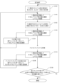
- FIG. 3 is a flow chart showing an example of the leveling amount correction control flow in the leveling control device of the first embodiment.
- the torque of the steel plate 1 on the delivery side of the F7 stand 70 is measured by the shape meter 97, and the torque applied in the width direction of the steel plate 1 is measured by the torque acquisition unit 161 of the leveling control device 150.
- the primary component in the width direction of the steel sheet 1 is determined in the primary component calculator 162 (step S101).
- the leveling correction amount calculation unit 163 of the leveling control device 150 calculates the leveling correction amount of the F7 stand 70 in consideration of the primary component obtained in step S101, and the leveling amount change unit 164 changes the leveling amount. (Step S102).
- the primary component of the tension distribution of the steel plate 1 between the F6 stand 60 and the F7 stand 70 is obtained in the same manner as the F7 stand 70 (final stand) delivery side (step S103).
- the leveling correction amount calculation unit 163 calculates the leveling correction amount of the F6 stand 60 in consideration of the primary component obtained in step S103, and the leveling amount change unit 164 changes the leveling amount (step S104). .
- steps S101 and S102 or steps S103 and S104 are also executed for the F5 stand 50, F4 stand 40, F3 stand 30, F2 stand 20, and F1 stand 10 (steps S105, S106, S106 and S106, respectively).
- steps S107, S108, S109, S110, S111, S112, S113, S114 are also executed for the F5 stand 50, F4 stand 40, F3 stand 30, F2 stand 20, and F1 stand 10 (steps S105, S106, S106 and S106, respectively).
- S107, S108, S109, S110, S111, S112, S113, S114 are also executed for the F5 stand 50, F4 stand 40, F3 stand 30, F2 stand 20, and F1 stand 10 (steps S105, S106, S106 and S106, respectively).
- S107, S108, S109, S110, S111, S112, S113, S114 are also executed for the F5 stand 50, F4 stand 40, F3 stand 30, F2 stand 20, and F1 stand 10 (step
- step S121 when the leveling is corrected on the upstream side, the effect is propagated to the downstream side, so the leveling correction amount of the F7 stand 70 is calculated with the plate wedge ratio constant for the leveling correction amount of the F6 stand 60 (step S121 ), it is desirable to reflect this in the processing in step S102.
- step S121 The processing of this step S121 is the same for the F5 stand, etc., and the corrections of the F1 stand 10, F2 stand 20, F3 stand 30, F4 stand 40, F5 stand 50, and F6 stand 60 are fixed, and each stand is calculated (corresponding to steps S122, S123, S124, S125, and S126), and can be reflected in the processing in step S102 and the like.
- step S121 the number of times step S121 is executed is recorded, and when a predetermined number of times is executed, the execution of steps S121, . . . , S126 is stopped.
- it is desirable to take measures such as stopping after a certain period of time has passed since the first execution, or stopping the execution of the process when the amount of correction in steps S121, . .
- step S130 it is determined whether or not the primary component of the tension distribution of the steel plate 1 on each exit side of all the stands satisfies the allowable value (step S130).
- Control parameter information of the obtained leveling amount is output to each screw down device 11, 21, 31, 41, 51, 61, 71).
- the process returns to step S101, and the process of obtaining the control parameter for the leveling amount is continued until all the stand exit sides satisfy the allowable value.
- steps S101 and S103 correspond to the torque acquisition process and the primary component calculation process
- steps S102, S104, S114, and S126 correspond to the leveling correction amount calculation process and the leveling amount change process.
- the leveling control device 150 in the rolling facility 200 of the first embodiment of the present invention described above is provided between the F1 stand 10, the F2 stand 20, the F3 stand 30, the F4 stand 40, the F5 stand 50, the F6 stand 60, and the F7 stand 70. From the torque measured by each shape meter 91, 92, 93, 94, 95, 96, each of F1 stand 10, F2 stand 20, F3 stand 30, F4 stand 40, F5 stand 50, F6 stand 60, F7 A torque acquisition unit 161 that obtains the torque distribution applied in the width direction of the steel plate 1 between the stands 70, and the tension distribution in the width direction is obtained from the obtained torque distribution, and the tension distribution of the steel plate 1 is represented by a polynomial from the tension distribution.
- the leveling correction amount calculation unit 163 obtains the leveling correction amount so that the obtained first-order component is within the allowable range, the first-order component can be reduced and the plate wedge ratio becomes nearly constant. can be rolled while maintaining , and the meandering of the steel sheet 1 can be reduced, and more stable rolling can be achieved.
- the leveling amount changing unit 164 changes the leveling amount of the F7 stand 70 before the (last-1) stage stand.
- a meandering amount calculation unit 165 is further provided for determining the amount of deviation between the center of the width direction of the steel sheet 1 and the rolling center between 70, and the first-order component calculation unit 162 calculates By correcting the torque distribution in the width direction, the torque difference can be corrected by the amount of deviation, and the primary component can be obtained with higher accuracy. Therefore, it is possible to further improve the accuracy of the reduction control.
- FIG. 4 is a schematic diagram showing the configuration of a rolling facility equipped with the leveling control device of the second embodiment
- FIG. 5 is a flow chart showing an example of the flow of leveling amount correction control.
- the rolling facility 200A of the present embodiment shown in FIG. 4 measures the thickness distribution in the width direction of the steel sheet 1 instead of the shape meter 97 provided on the delivery side of the F7 stand 70 in the rolling facility 200 of the first embodiment described above.
- a plate wedge amount measuring device 98 is provided. Note that the plate wedge amount measuring device 98 may be a plate thickness meter or a profile meter as long as it is a measuring device capable of measuring data for calculating the plate wedge amount.
- the leveling control device 150A further includes a plate wedge amount acquisition section 167A.
- the plate wedge amount acquisition unit 167A determines the plate wedge of the steel sheet 1 on the rolling downstream side of the F7 stand 70 from the plate thickness distribution in the width direction measured by the plate wedge amount measuring device 98 provided on the rolling downstream side of the F7 stand 70. ask for quantity.
- the leveling correction amount calculation unit 163A obtains the leveling correction amount of the F7 stand 70 based on the plate wedge amount obtained by the plate wedge amount obtaining unit 167A, and the leveling amount change unit 164A obtains the (final -1) level. It also changes the leveling amount of the F7 stand 70 before the stand.
- the plate wedge transfer rate is considered to be almost 0, and the plate wedge (plate wedge ratio) before rolling is thought to be inherited as it is.
- the leveling correction amount of the F7 stand is calculated to adjust the oil column difference between the drive side and work side screw down devices 71.
- the plate wedge of the steel plate 1 on the delivery side of the F7 stand 70 is measured by the plate wedge amount measuring device 98 and the plate wedge amount acquisition unit 167A of the leveling control device 150A (step S201).
- the leveling correction amount calculation unit 163A of the leveling control device 150A calculates the leveling correction amount of the F7 stand 70 in consideration of the plate wedge obtained in step S101, and the leveling amount changing unit 164 changes the leveling amount. (Step S202).
- a known method may be used to calculate the amount of leveling correction from the determined plate wedge.
- step S203 to step S230 is the same as the processing from step S103 to step S130 in FIG. 3 described above, and details thereof will be omitted.
- the leveling control device, the rolling equipment having the same, and the leveling control method of the second embodiment of the present invention are also substantially the same as the leveling control device, the rolling equipment having the same, and the leveling control method of the first embodiment. A similar effect can be obtained.
- the leveling correction amount calculation unit 163A obtains the leveling correction amount of the F7 stand 70 based on the plate wedge amount obtained by the plate wedge amount obtaining unit 167A, and the leveling amount changing unit 164A obtains ( Final-1) By changing the leveling amount of the F7 stand 70 before the step stand, even if the shape data cannot be used on the delivery side of the F7 stand 70, the accuracy of the reduction control can be further improved.
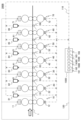
- FIG. 6 is a schematic diagram showing the configuration of a rolling facility equipped with the leveling control device of the third embodiment
- FIG. 7 is a flow chart showing an example of the flow of correction control of the leveling amount.
- the rolling facility 200B of the present embodiment shown in FIG. 6 does not have the shape meter 97 of the rolling facility 200 of the first embodiment or the plate wedge amount measuring device 98 of the rolling facility 200A of the second embodiment, and is the final stage.
- This is a form in which calculated values are assumed when the data of the plate wedge amount and tension distribution of the steel plate 1 on the delivery side of the F7 stand 70 are not obtained.
- the rolling upstream side of F7 stand 70 A plate wedge amount calculation unit 168B that obtains the plate wedge amount of the steel plate 1 is further provided.
- the leveling correction amount calculation unit 163B of the leveling control device 150B obtains the leveling correction amount of the F7 stand 70 based on the plate wedge amount obtained by the plate wedge amount calculation unit 168B, and the leveling amount change unit 164B calculates ( Last-1) The leveling amount of the F7 stand 70 is also changed before the number stand.
- plate wedges are formed so as to substantially follow the leveling in the preceding F1 stand 10 and F2 stand 20, that is, transfer is dominant.
- the wedge (ratio) that enters the rolling stand also appears on the delivery side in order to avoid large deformation in the shape of the F3 stand 30 and subsequent stands, that is, heredity is dominant.
- the plate wedge on the exit side of each stand it is possible to estimate the plate wedge on the exit side of each stand. Therefore, once the plate wedge on the entry side of the F7 stand 70, which is the final stage, can be calculated, and if the leveling of the F7 stand 70 is changed based on the calculated plate wedge amount on the exit side of the F6 stand 60, An influence occurs on the upstream side, and the tension components of the shape meters 91, 92, 93, 94, 95, 96 change. After that, as in the first and second embodiments, the leveling amount can be changed and controlled toward the upstream.
- each stand should independently control the amount of leveling and calculate the plate wedge. For example, calculation of the plate wedge in steps S301 to S306 is always performed, and leveling change processing in steps S307 to S330 is performed between the start and end.
- the delivery side of the F1 stand 10 is calculated using the actually measured rolling load P, the roll profile prediction value Cw, and the actually measured leveling ⁇ S at the F1 stand 10 . is calculated (step S301).
- the plate wedge amount calculation unit 168B the plate wedge calculation value on the delivery side of the F1 stand 10 obtained in the previous step S301, the measured rolling load P of the F2 stand 20, the roll profile prediction value Cw, and the measured leveling ⁇ S are used.
- a plate wedge on the delivery side of the F2 stand 20 is calculated (step S302).
- steps S301 and S302 are also executed for the F3 stand 30, F4 stand 40, F5 stand 50, and F6 stand 60 (corresponding to steps S303, S304, S305, and S306, respectively).
- step S306 a step corresponding to step S306 before rolling is performed.
- the leveling correction amount of the F7 stand 70 is calculated in consideration of the plate wedge (plate wedge ratio) on the delivery side of the F6 stand 60 calculated in 1, and the leveling amount is changed in the leveling amount changing unit 164B (step S307).
- step S308 and subsequent steps are basically the same as the processing from step S103 to step S130 in FIG. 3 described above, and the details are omitted.
- the difference is that when it is determined in step S330 that even one stand is not satisfied, the process returns to step S307, and the process of obtaining the control parameter for the leveling amount is continued until all stands are satisfied.
- the leveling control device, the rolling equipment having the same, and the leveling control method of the third embodiment of the present invention are also substantially the same as the leveling control device, the rolling equipment having the same, and the leveling control method of the first embodiment. A similar effect can be obtained.
- a plate wedge amount calculation unit 168B that obtains the plate wedge amount of the steel plate 1 on the upstream side of the rolling of the F7 stand 70 is further provided.
- the leveling amount changing unit 164B also changes the leveling amount of the F7 stand 70 before the (last-1)th stand, thereby making various changes on the delivery side of the F7 stand 70. Even when such data cannot be used, the accuracy of the reduction control can be further improved.
Landscapes
- Engineering & Computer Science (AREA)
- Mechanical Engineering (AREA)
- Control Of Metal Rolling (AREA)
Abstract
Priority Applications (3)
| Application Number | Priority Date | Filing Date | Title |
|---|---|---|---|
| EP21956708.8A EP4374983A1 (fr) | 2021-09-07 | 2021-09-07 | Dispositif de commande de mise à niveau, équipement de laminage muni de celui-ci, et procédé de commande de mise à niveau |
| PCT/JP2021/032839 WO2023037409A1 (fr) | 2021-09-07 | 2021-09-07 | Dispositif de commande de mise à niveau, équipement de laminage muni de celui-ci, et procédé de commande de mise à niveau |
| JP2023546593A JPWO2023037409A1 (fr) | 2021-09-07 | 2021-09-07 |
Applications Claiming Priority (1)
| Application Number | Priority Date | Filing Date | Title |
|---|---|---|---|
| PCT/JP2021/032839 WO2023037409A1 (fr) | 2021-09-07 | 2021-09-07 | Dispositif de commande de mise à niveau, équipement de laminage muni de celui-ci, et procédé de commande de mise à niveau |
Publications (1)
| Publication Number | Publication Date |
|---|---|
| WO2023037409A1 true WO2023037409A1 (fr) | 2023-03-16 |
Family
ID=85507279
Family Applications (1)
| Application Number | Title | Priority Date | Filing Date |
|---|---|---|---|
| PCT/JP2021/032839 WO2023037409A1 (fr) | 2021-09-07 | 2021-09-07 | Dispositif de commande de mise à niveau, équipement de laminage muni de celui-ci, et procédé de commande de mise à niveau |
Country Status (3)
| Country | Link |
|---|---|
| EP (1) | EP4374983A1 (fr) |
| JP (1) | JPWO2023037409A1 (fr) |
| WO (1) | WO2023037409A1 (fr) |
Citations (4)
| Publication number | Priority date | Publication date | Assignee | Title |
|---|---|---|---|---|
| JPS6329605A (ja) | 1986-07-14 | 1988-02-08 | ユリウス・ブルム・ゲゼルシヤフト・ミツト・ベシユレンクテル・ハフツング | 引出し |
| JPS6329605B2 (fr) * | 1980-11-14 | 1988-06-14 | Hitachi Ltd | |
| JPH1133615A (ja) * | 1997-07-18 | 1999-02-09 | Nkk Corp | タンデム圧延機における蛇行制御方法及び装置 |
| WO2012086043A1 (fr) * | 2010-12-24 | 2012-06-28 | 三菱日立製鉄機械株式会社 | Équipement de laminage à chaud et procédé de laminage à chaud |
-
2021
- 2021-09-07 EP EP21956708.8A patent/EP4374983A1/fr active Pending
- 2021-09-07 JP JP2023546593A patent/JPWO2023037409A1/ja active Pending
- 2021-09-07 WO PCT/JP2021/032839 patent/WO2023037409A1/fr active Application Filing
Patent Citations (4)
| Publication number | Priority date | Publication date | Assignee | Title |
|---|---|---|---|---|
| JPS6329605B2 (fr) * | 1980-11-14 | 1988-06-14 | Hitachi Ltd | |
| JPS6329605A (ja) | 1986-07-14 | 1988-02-08 | ユリウス・ブルム・ゲゼルシヤフト・ミツト・ベシユレンクテル・ハフツング | 引出し |
| JPH1133615A (ja) * | 1997-07-18 | 1999-02-09 | Nkk Corp | タンデム圧延機における蛇行制御方法及び装置 |
| WO2012086043A1 (fr) * | 2010-12-24 | 2012-06-28 | 三菱日立製鉄機械株式会社 | Équipement de laminage à chaud et procédé de laminage à chaud |
Also Published As
| Publication number | Publication date |
|---|---|
| JPWO2023037409A1 (fr) | 2023-03-16 |
| EP4374983A1 (fr) | 2024-05-29 |
Similar Documents
| Publication | Publication Date | Title |
|---|---|---|
| US6230532B1 (en) | Method and apparatus for controlling sheet shape in sheet rolling | |
| JP5734112B2 (ja) | 圧延機での板厚制御方法 | |
| WO2023037409A1 (fr) | Dispositif de commande de mise à niveau, équipement de laminage muni de celui-ci, et procédé de commande de mise à niveau | |
| JP4267609B2 (ja) | 金属板材の圧延方法および圧延装置 | |
| JP2010540250A5 (fr) | ||
| JP2018015766A (ja) | 熱間仕上圧延における鋼板尾端蛇行制御方法 | |
| JP3589226B2 (ja) | 被圧延材の蛇行制御方法 | |
| JP4288888B2 (ja) | タンデム圧延機におけるストリップの蛇行制御装置及び蛇行制御方法 | |
| JP4232230B2 (ja) | 熱間仕上圧延機のレベリング制御方法及び装置 | |
| CN112439795A (zh) | 蛇行控制装置 | |
| JP5158772B2 (ja) | 圧延機の板厚制御装置及び圧延機の板厚制御方法 | |
| JP2015037802A (ja) | 蛇行制御装置および蛇行制御方法 | |
| CN114054514B (zh) | 轧机的蛇行控制装置 | |
| TWI782641B (zh) | 串列式冷壓延機的控制系統 | |
| KR100929015B1 (ko) | 압연재 소성계수 보정에 의한 예측압연하중 보정방법 | |
| JP7298019B2 (ja) | 圧延機および圧延方法 | |
| JP2019107675A (ja) | 圧延機の制御装置および制御方法 | |
| JP6601451B2 (ja) | 圧延機の制御方法、圧延機の制御装置、および熱延鋼板の製造方法 | |
| JP6743835B2 (ja) | 形鋼の圧延方法及び形鋼の圧延におけるレベリング量の調整方法 | |
| JPH08294714A (ja) | 金属板圧延におけるキャンバ低減方法 | |
| JP2001269708A (ja) | 熱間圧延機のレベリング制御方法及び装置 | |
| KR20220152393A (ko) | 연속식 압연기의 사행 제어 장치 | |
| JP2000301221A (ja) | 冷間圧延時のエッジドロップ制御方法 | |
| JPS62244513A (ja) | 連続式圧延機の板厚制御方法 | |
| JP2950182B2 (ja) | テーパー鋼板の製造方法 |
Legal Events
| Date | Code | Title | Description |
|---|---|---|---|
| 121 | Ep: the epo has been informed by wipo that ep was designated in this application |
Ref document number: 21956708 Country of ref document: EP Kind code of ref document: A1 |
|
| WWE | Wipo information: entry into national phase |
Ref document number: 2023546593 Country of ref document: JP |
|
| WWE | Wipo information: entry into national phase |
Ref document number: 2021956708 Country of ref document: EP |
|
| ENP | Entry into the national phase |
Ref document number: 2021956708 Country of ref document: EP Effective date: 20240222 |
|
| NENP | Non-entry into the national phase |
Ref country code: DE |