WO2023037409A1 - Leveling control device, rolling equipment provided with same, and leveling control method - Google Patents
Leveling control device, rolling equipment provided with same, and leveling control method Download PDFInfo
- Publication number
- WO2023037409A1 WO2023037409A1 PCT/JP2021/032839 JP2021032839W WO2023037409A1 WO 2023037409 A1 WO2023037409 A1 WO 2023037409A1 JP 2021032839 W JP2021032839 W JP 2021032839W WO 2023037409 A1 WO2023037409 A1 WO 2023037409A1
- Authority
- WO
- WIPO (PCT)
- Prior art keywords
- leveling
- stand
- rolling
- amount
- control device
- Prior art date
Links
- 238000005096 rolling process Methods 0.000 title claims abstract description 128
- 238000000034 method Methods 0.000 title claims description 39
- 229910000831 Steel Inorganic materials 0.000 claims abstract description 82
- 239000010959 steel Substances 0.000 claims abstract description 82
- 238000012937 correction Methods 0.000 claims abstract description 68
- 238000011144 upstream manufacturing Methods 0.000 claims abstract description 24
- 238000005098 hot rolling Methods 0.000 claims description 6
- 238000012545 processing Methods 0.000 description 12
- 238000004891 communication Methods 0.000 description 11
- 238000005452 bending Methods 0.000 description 8
- 230000000694 effects Effects 0.000 description 6
- 230000000875 corresponding effect Effects 0.000 description 5
- 238000010586 diagram Methods 0.000 description 5
- 239000000463 material Substances 0.000 description 3
- 238000005259 measurement Methods 0.000 description 3
- 238000012546 transfer Methods 0.000 description 3
- 239000000470 constituent Substances 0.000 description 2
- 230000001276 controlling effect Effects 0.000 description 2
- 230000002596 correlated effect Effects 0.000 description 2
- 238000001514 detection method Methods 0.000 description 2
- 230000000644 propagated effect Effects 0.000 description 2
- 238000007796 conventional method Methods 0.000 description 1
- 238000011161 development Methods 0.000 description 1
- 230000001771 impaired effect Effects 0.000 description 1
- 239000007769 metal material Substances 0.000 description 1
- 238000012986 modification Methods 0.000 description 1
- 230000004048 modification Effects 0.000 description 1
- 239000003607 modifier Substances 0.000 description 1
Images


Classifications
-
- B—PERFORMING OPERATIONS; TRANSPORTING
- B21—MECHANICAL METAL-WORKING WITHOUT ESSENTIALLY REMOVING MATERIAL; PUNCHING METAL
- B21B—ROLLING OF METAL
- B21B37/00—Control devices or methods specially adapted for metal-rolling mills or the work produced thereby
- B21B37/58—Roll-force control; Roll-gap control
Definitions
- the present invention relates to a leveling control device, a rolling facility equipped with the same, and a leveling control method.
- Patent Document 1 discloses that a strip is sequentially passed through a plurality of rolling mill stands arranged in series, and the strip is simultaneously rolled at each rolling mill stand.
- a method of controlling plate bending in a tandem mill that adjusts the amount of lateral reduction of each rolling mill stand based on the detected value of the tension deviation to remove the lateral tension deviation of the strip between each rolling mill stand, thereby controlling plate bending , adjustment of the reduction amount of the rolling mill stand is performed on the front side of the detection position based on the detected value of the lateral tension deviation of the strip coming out of the rolling mill stand, and this adjustment operation is sequentially performed toward the rolling mill stand on the entry side. It is stated that it will proceed.
- Patent Document 1 discloses that, based on the left and right tension deviation of the strip between each rolling mill stand, roll-down control is performed at the stand on the front side of the tension detection position, and this control is sequentially advanced to the entry side.
- the present invention provides a leveling control device that can improve the accuracy of roll reduction control of each stand of a hot rolling line in which a plurality of rolling stands are arranged compared to the conventional one, rolling equipment equipped with the same, and leveling control provide a way.
- the present invention includes a plurality of means for solving the above problems.
- One example is a leveling control device for a hot rolling line in which a plurality of rolling stands are arranged, wherein the leveling control device between the plurality of rolling stands From the results measured by each shape meter provided in, a torque acquisition unit that obtains the torque distribution applied in the width direction of the steel plate between each of the plurality of rolling stands, and the width direction from the obtained torque distribution a primary component calculation unit that obtains a tension distribution and obtains a primary component when the tension distribution of the steel sheet is represented by a polynomial from the tension distribution; and based on the obtained primary component, the plurality of rolling stands.
- a leveling correction amount calculation unit that obtains the leveling correction amount of the rolling stand immediately before the upstream side of the rolling, and based on the obtained leveling correction amount, the stand of the (last -1) stage among the plurality of rolling stands and a leveling amount changing unit that changes the leveling amount in order from the upstream side of the rolling.
- FIG. 5 is a diagram showing an example of a determination method within the allowable range of the primary component in the leveling control device of the first embodiment; 4 is a flowchart showing an example of the flow of leveling amount correction control in the leveling control device of the first embodiment; Schematic which shows the structure of the rolling equipment provided with the leveling control apparatus of Example 2 of this invention. 9 is a flow chart showing an example of the flow of leveling amount correction control in the leveling control device of the second embodiment. Schematic which shows the structure of the rolling equipment provided with the leveling control apparatus of Example 3 of this invention. 10 is a flow chart showing an example of the flow of leveling amount correction control in the leveling control device of the third embodiment.
- the material to be rolled in the present invention is not limited to a steel plate, but can be a strip of a metal material that can be rolled in general, and the type is not particularly limited. Non-ferrous materials can be targeted.
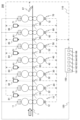
- FIG. 1 is a schematic diagram showing the structure of a rolling facility equipped with a leveling control device according to the first embodiment.
- a rolling facility 200 shown in FIG. 1 is a finish rolling facility for rolling a steel plate 1, and includes an F1 stand 10, an F2 stand 20, an F3 stand 30, an F4 stand 40, an F5 stand 50, an F6 stand 60, and an F7 stand 70. , cameras 81, 82, 83, 84, 85, 86, shape meters 91, 92, 93, 94, 95, 96, 97, a leveling control device 150, and the like.
- the rolling facility 200 is not limited to the configuration in which seven rolling stands are provided as shown in FIG. 1, and may have at least three stands.
- Each of the F1 stand 10, the F2 stand 20, the F3 stand 30, the F4 stand 40, the F5 stand 50, the F6 stand 60, and the F7 stand 70 has an upper work roll and a lower work roll, and the upper work roll and the lower work roll, respectively.
- Information on the rolling load measured by the load detectors 12 , 22 , 32 , 42 , 52 , 62 , 72 is transmitted to the leveling controller 150 via the communication line 110 .
- a six-stage configuration may be employed in which upper and lower intermediate rolls are further provided between each of the upper and lower work rolls and each of the upper and lower backup rolls.
- the roll configuration of the rolling mill is not limited to the form described above, and it is sufficient that there are at least upper and lower work rolls.
- Shape meters 91, 92, 93, 94, 95, and 96 are provided between F1 stand 10, F2 stand 20, F3 stand 30, F4 stand 40, F5 stand 50, F6 stand 60, and F7 stand 70, respectively. , is a measuring instrument for measuring the torque of the steel plate 1 . Moreover, the tension distribution in the width direction of the sheet can be detected, and the position of the steel sheet 1 can also be detected.
- Information on the surface shape of the steel plate 1 at the F1 stand 10 exit side (F2 stand 20 entry side) measured by the shape meter 91 is transmitted to the leveling control device 150 via the communication line 110 .
- Information on the surface shape of the steel plate 1 at the exit side of the F2 stand 20 (the entrance side of the F3 stand 30) measured by the shape meter 92 is transmitted to the leveling control device 150 via the communication line 110 .
- Information on the surface shape of the steel plate 1 at the F3 stand 30 exit side (F4 stand 40 entry side) measured by the shape meter 93 is transmitted to the leveling control device 150 via the communication line 110 .
- Information on the surface shape of the steel plate 1 at the F4 stand 40 exit side (F5 stand 50 entry side) measured by the shape meter 94 is transmitted to the leveling control device 150 via the communication line 110 .
- Information on the surface shape of the steel plate 1 at the F5 stand 50 exit side (F6 stand 60 entry side) measured by the shape meter 95 is transmitted to the leveling control device 150 via the communication line 110 .
- Information on the surface shape of the steel plate 1 at the exit side of the F6 stand 60 (the entrance side of the F7 stand 70) measured by the shape meter 96 is transmitted to the leveling control device 150 via the communication line 110 .
- the shape meter 97 is also a measuring instrument for measuring the surface shape of the steel plate 1, like the shape meter 91 and the like, and is provided on the exit side of the F7 stand 70. Information on the surface shape of the steel plate 1 on the delivery side of the F7 stand 70 measured by the shape meter 97 is transmitted to the leveling control device 150 via the communication line 110 .
- the camera 81 is provided at a position capable of capturing an image including the steel plate 1 on the exit side of the F1 stand 10 and the entry side of the F2 stand 20.
- the camera 82 is provided at a position capable of capturing an image including the steel plate 1 on the exit side of the F2 stand 20 and the entrance side of the F3 stand 30 .
- the camera 83 is provided at a position capable of capturing an image including the steel plate 1 on the exit side of the F3 stand 30 and the entrance side of the F4 stand 40 .
- the camera 84 is provided at a position capable of capturing an image including the steel plate 1 on the exit side of the F4 stand 40 and the entrance side of the F5 stand 50 .
- the camera 85 is provided at a position capable of capturing an image including the steel plate 1 on the exit side of the F5 stand 50 and the entry side of the F6 stand 60 .
- the camera 86 is provided at a position capable of capturing an image including the steel plate 1 on the delivery side of the F6 stand 60 and the entry side of the F7 stand 70 .
- These cameras 81 , 82 , 83 , 84 , 85 , 86 capture images including the steel plate 1 directly above or obliquely above the steel plate 1 at intervals of, for example, less than 0.1 seconds, preferably in the form of moving images.
- the data of the captured image is transmitted to the leveling control device 150 via the communication line 110 .
- the leveling control device 150 is a device configured by a computer or the like that controls the operation of each device in the rolling mill 200, and includes a torque acquisition unit 161, a primary component calculation unit 162, a leveling correction amount calculation unit 163, and a leveling amount change. It has a section 164, a meandering amount calculation section 165, a storage section 166, and the like.
- the torque acquisition unit 161 is provided between the F1 stand 10, the F2 stand 20, the F3 stand 30, the F4 stand 40, the F5 stand 50, the F6 stand 60, and the F7 stand 70. From the torque measured by 95, 96, the torque distribution across the width of the steel plate 1 between each of the F1 stand 10, F2 stand 20, F3 stand 30, F4 stand 40, F5 stand 50, F6 stand 60, F7 stand 70 Ask for This torque acquisition unit 161 preferably serves as an execution subject of the torque acquisition process.
- the torque acquisition unit 161 applies the torque of the steel sheet 1 in the width direction of the steel sheet 1 on the downstream side of the rolling of the F7 stand 70 from the torque of the steel sheet 1 acquired by the shape meter 97 provided on the rolling downstream side of the final F7 stand 70. Find the torque distribution.
- the meandering amount calculation unit 165 calculates the results measured by the plate position detectors provided between the F1 stand 10, F2 stand 20, F3 stand 30, F4 stand 40, F5 stand 50, F6 stand 60, and F7 stand 70. , the amount of deviation between the center of the width direction of the steel sheet 1 and the center of rolling between each of the F1 stand 10, F2 stand 20, F3 stand 30, F4 stand 40, F5 stand 50, F6 stand 60, and F7 stand is obtained.
- the plate position detectors that acquire the measurement results used by the meandering amount calculation unit 165 are the cameras 81, 82, 83, 84, 85, and 86 described above, or the shape meters 91, 92, 93, 94, 95, 96, and 97. is.
- the first-order component calculation unit 162 obtains the tension distribution in the width direction of the steel plate 1 from the torque distribution obtained by the torque obtaining unit 161 . Also, from the obtained tension distribution, a primary component is obtained when the tension distribution of the steel sheet 1 is represented by a polynomial. At this time, the first-order component calculation section 162 can correct the torque distribution in the width direction of the steel sheet 1 based on the deviation amount (the meandering amount ⁇ Yc in FIG. 2) obtained by the meandering amount calculating section 165 .
- the first-order component calculation unit 162 preferably serves as the execution body of the first-order component calculation process.
- the leveling correction amount calculation unit 163 obtains the leveling correction amounts of the rolling stands 10, 20, 30, 40, 50, and 60 immediately before the rolling upstream side based on the primary components obtained by the primary component calculation unit 162. Moreover, it is desirable that the leveling correction amount calculation section 163 obtains the leveling correction amount of the F7 stand 70 based on the first-order component obtained in the first-order component calculation section 162 . This leveling correction amount calculation unit 163 preferably serves as the executing body of the leveling correction amount calculation step.
- the leveling correction amount calculation unit 163 uses the primary component of the tension distribution obtained from the torque of the steel plate 1 measured by the shape meter 96 provided on the delivery side of the F6 stand 60 to adjust the F6 stand. Makes 60 leveling modifiers. This processing is sequentially executed toward the upstream side of the rolling.
- the shape meter 96 of the F7 stand 70 begins to descend vertically downward (from the steel plate 1 from this timing onwards, leveling correction of the F6 stand 60 and the F7 stand 70 is performed using the amount of meandering of the steel plate 1 input from the camera 85 in front of the F6 stand 60 and the camera 86 in front of the F7 stand 70. is desirable. More specifically, the off-center amount between the F5 stand 50 and the F6 stand 60 is used to correct the leveling of the F6 stand 60, and the off-center amount between the F6 stand 60 and the F7 stand 70 is used to correct the leveling of the F7 stand 70. is desirable.
- the leveling correction amount calculation unit 163 can obtain the leveling correction amount so that the obtained first-order component is within the allowable range.
- FIG. 2 is a diagram showing an example of a method of determining within the allowable range of the primary component.
- FIG. 2 shows the timing when the tail end of the steel plate 1 is pulled out of the F6 stand 60. Since the steel plate 1 is pulled out of the F6 stand 60, only the F7 stand 70 gives the left and right binding forces to the steel plate 1. There is a possibility that the steel plate 1 will meander greatly.
- H is the average thickness of the steel plate 1 on the entry side of the F7 stand 70
- ⁇ H is the difference in thickness between both ends of the steel plate 1 on the entry side
- h is the average thickness of the steel plate 1 on the exit side of the F7 stand 70
- h is the exit side.
- ⁇ h be the difference in thickness between both ends of the steel plate 1
- ⁇ Yc be the difference between the center of the F7 stand 70 in the width direction and the center of the steel plate 1 in the width direction, that is, the meandering amount of the steel plate 1
- the amount of meandering .DELTA.Yc is obtained using the plate rotation angular velocity at the tail end and the plate speed moving in the width direction of the plate.
- the plate rotation angular velocity and the plate speed are obtained using the plate wedge ratio change ( ⁇ h/h ⁇ H/H). Furthermore, when the tension distribution of the steel plate 1 is represented by a polynomial, the first-order component (elongation difference ratio) is correlated with the plate wedge ratio change ( ⁇ h / h - ⁇ H / H), and the leveling amount (difference in reduction ratio) is also correlated with ⁇ H and ⁇ h and can be calculated. Based on the results, the maximum value of the allowable meandering amount ⁇ Yc (for example, the meandering amount ⁇ Yc at the F7 stand 70 when the tail end of the steel plate 1 contacts the side guide (not shown)) is determined. It is also possible to calculate the degree of the primary component of the torque distribution applied in the width direction of the steel plate 1 on the exit side of the F7 stand 70 at the maximum possible meandering amount ⁇ Yc.
- the allowable meandering amount ⁇ Yc for example, the meandering amount ⁇ Yc at the F
- the leveling correction amount calculation unit 163 sets the range of the first order component of the torque distribution in which the amount of meandering ⁇ Yc can be kept within the allowable range, and the first order component obtained by the first order component calculation unit 162 is set as the allowable range.
- a leveling correction amount can be obtained so as to be within the allowable range.
- the leveling amount changing section 164 Based on the leveling correction amount obtained by the leveling correction amount calculating section 163, the leveling amount changing section 164 adjusts the F1 stand 10, the F2 stand 20, the F3 stand 30, the F4 stand 40, the F5 stand 50, the F6 stand 60, and the F7 stand. 70, the amount of leveling is changed in order from the (last-1) stand toward the upstream side of the rolling. Moreover, it is desirable that the leveling amount changing unit 164 also changes the leveling amount of the F7 stand 70 before changing the leveling amount of the (last-1) stage stand.
- the leveling amount changing unit 164 preferably serves as the executing body of the leveling amount changing process.
- the leveling amount changing unit 164 outputs the obtained control parameter information of the leveling amount to each of the screw-down devices 11, 21, 31, 41, 51, 61, and 71 via the communication line 120. , 21, 31, 41, 51, 61, and 71 operate to implement the input leveling amount.
- the storage unit 166 is a computer storage device that constitutes the leveling control device 150, and is preferably configured with an SSD or HDD.
- control processing of the operations executed by the leveling control device 150 may be integrated into one program, may be separated into a plurality of programs, or may be a combination thereof. Also, part or all of the program may be realized by dedicated hardware, or may be modularized.
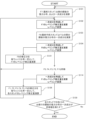
- FIG. 3 is a flow chart showing an example of the leveling amount correction control flow in the leveling control device of the first embodiment.
- the torque of the steel plate 1 on the delivery side of the F7 stand 70 is measured by the shape meter 97, and the torque applied in the width direction of the steel plate 1 is measured by the torque acquisition unit 161 of the leveling control device 150.
- the primary component in the width direction of the steel sheet 1 is determined in the primary component calculator 162 (step S101).
- the leveling correction amount calculation unit 163 of the leveling control device 150 calculates the leveling correction amount of the F7 stand 70 in consideration of the primary component obtained in step S101, and the leveling amount change unit 164 changes the leveling amount. (Step S102).
- the primary component of the tension distribution of the steel plate 1 between the F6 stand 60 and the F7 stand 70 is obtained in the same manner as the F7 stand 70 (final stand) delivery side (step S103).
- the leveling correction amount calculation unit 163 calculates the leveling correction amount of the F6 stand 60 in consideration of the primary component obtained in step S103, and the leveling amount change unit 164 changes the leveling amount (step S104). .
- steps S101 and S102 or steps S103 and S104 are also executed for the F5 stand 50, F4 stand 40, F3 stand 30, F2 stand 20, and F1 stand 10 (steps S105, S106, S106 and S106, respectively).
- steps S107, S108, S109, S110, S111, S112, S113, S114 are also executed for the F5 stand 50, F4 stand 40, F3 stand 30, F2 stand 20, and F1 stand 10 (steps S105, S106, S106 and S106, respectively).
- S107, S108, S109, S110, S111, S112, S113, S114 are also executed for the F5 stand 50, F4 stand 40, F3 stand 30, F2 stand 20, and F1 stand 10 (steps S105, S106, S106 and S106, respectively).
- S107, S108, S109, S110, S111, S112, S113, S114 are also executed for the F5 stand 50, F4 stand 40, F3 stand 30, F2 stand 20, and F1 stand 10 (step
- step S121 when the leveling is corrected on the upstream side, the effect is propagated to the downstream side, so the leveling correction amount of the F7 stand 70 is calculated with the plate wedge ratio constant for the leveling correction amount of the F6 stand 60 (step S121 ), it is desirable to reflect this in the processing in step S102.
- step S121 The processing of this step S121 is the same for the F5 stand, etc., and the corrections of the F1 stand 10, F2 stand 20, F3 stand 30, F4 stand 40, F5 stand 50, and F6 stand 60 are fixed, and each stand is calculated (corresponding to steps S122, S123, S124, S125, and S126), and can be reflected in the processing in step S102 and the like.
- step S121 the number of times step S121 is executed is recorded, and when a predetermined number of times is executed, the execution of steps S121, . . . , S126 is stopped.
- it is desirable to take measures such as stopping after a certain period of time has passed since the first execution, or stopping the execution of the process when the amount of correction in steps S121, . .
- step S130 it is determined whether or not the primary component of the tension distribution of the steel plate 1 on each exit side of all the stands satisfies the allowable value (step S130).
- Control parameter information of the obtained leveling amount is output to each screw down device 11, 21, 31, 41, 51, 61, 71).
- the process returns to step S101, and the process of obtaining the control parameter for the leveling amount is continued until all the stand exit sides satisfy the allowable value.
- steps S101 and S103 correspond to the torque acquisition process and the primary component calculation process
- steps S102, S104, S114, and S126 correspond to the leveling correction amount calculation process and the leveling amount change process.
- the leveling control device 150 in the rolling facility 200 of the first embodiment of the present invention described above is provided between the F1 stand 10, the F2 stand 20, the F3 stand 30, the F4 stand 40, the F5 stand 50, the F6 stand 60, and the F7 stand 70. From the torque measured by each shape meter 91, 92, 93, 94, 95, 96, each of F1 stand 10, F2 stand 20, F3 stand 30, F4 stand 40, F5 stand 50, F6 stand 60, F7 A torque acquisition unit 161 that obtains the torque distribution applied in the width direction of the steel plate 1 between the stands 70, and the tension distribution in the width direction is obtained from the obtained torque distribution, and the tension distribution of the steel plate 1 is represented by a polynomial from the tension distribution.
- the leveling correction amount calculation unit 163 obtains the leveling correction amount so that the obtained first-order component is within the allowable range, the first-order component can be reduced and the plate wedge ratio becomes nearly constant. can be rolled while maintaining , and the meandering of the steel sheet 1 can be reduced, and more stable rolling can be achieved.
- the leveling amount changing unit 164 changes the leveling amount of the F7 stand 70 before the (last-1) stage stand.
- a meandering amount calculation unit 165 is further provided for determining the amount of deviation between the center of the width direction of the steel sheet 1 and the rolling center between 70, and the first-order component calculation unit 162 calculates By correcting the torque distribution in the width direction, the torque difference can be corrected by the amount of deviation, and the primary component can be obtained with higher accuracy. Therefore, it is possible to further improve the accuracy of the reduction control.
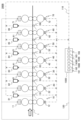
- FIG. 4 is a schematic diagram showing the configuration of a rolling facility equipped with the leveling control device of the second embodiment
- FIG. 5 is a flow chart showing an example of the flow of leveling amount correction control.
- the rolling facility 200A of the present embodiment shown in FIG. 4 measures the thickness distribution in the width direction of the steel sheet 1 instead of the shape meter 97 provided on the delivery side of the F7 stand 70 in the rolling facility 200 of the first embodiment described above.
- a plate wedge amount measuring device 98 is provided. Note that the plate wedge amount measuring device 98 may be a plate thickness meter or a profile meter as long as it is a measuring device capable of measuring data for calculating the plate wedge amount.
- the leveling control device 150A further includes a plate wedge amount acquisition section 167A.
- the plate wedge amount acquisition unit 167A determines the plate wedge of the steel sheet 1 on the rolling downstream side of the F7 stand 70 from the plate thickness distribution in the width direction measured by the plate wedge amount measuring device 98 provided on the rolling downstream side of the F7 stand 70. ask for quantity.
- the leveling correction amount calculation unit 163A obtains the leveling correction amount of the F7 stand 70 based on the plate wedge amount obtained by the plate wedge amount obtaining unit 167A, and the leveling amount change unit 164A obtains the (final -1) level. It also changes the leveling amount of the F7 stand 70 before the stand.
- the plate wedge transfer rate is considered to be almost 0, and the plate wedge (plate wedge ratio) before rolling is thought to be inherited as it is.
- the leveling correction amount of the F7 stand is calculated to adjust the oil column difference between the drive side and work side screw down devices 71.
- the plate wedge of the steel plate 1 on the delivery side of the F7 stand 70 is measured by the plate wedge amount measuring device 98 and the plate wedge amount acquisition unit 167A of the leveling control device 150A (step S201).
- the leveling correction amount calculation unit 163A of the leveling control device 150A calculates the leveling correction amount of the F7 stand 70 in consideration of the plate wedge obtained in step S101, and the leveling amount changing unit 164 changes the leveling amount. (Step S202).
- a known method may be used to calculate the amount of leveling correction from the determined plate wedge.
- step S203 to step S230 is the same as the processing from step S103 to step S130 in FIG. 3 described above, and details thereof will be omitted.
- the leveling control device, the rolling equipment having the same, and the leveling control method of the second embodiment of the present invention are also substantially the same as the leveling control device, the rolling equipment having the same, and the leveling control method of the first embodiment. A similar effect can be obtained.
- the leveling correction amount calculation unit 163A obtains the leveling correction amount of the F7 stand 70 based on the plate wedge amount obtained by the plate wedge amount obtaining unit 167A, and the leveling amount changing unit 164A obtains ( Final-1) By changing the leveling amount of the F7 stand 70 before the step stand, even if the shape data cannot be used on the delivery side of the F7 stand 70, the accuracy of the reduction control can be further improved.
- FIG. 6 is a schematic diagram showing the configuration of a rolling facility equipped with the leveling control device of the third embodiment
- FIG. 7 is a flow chart showing an example of the flow of correction control of the leveling amount.
- the rolling facility 200B of the present embodiment shown in FIG. 6 does not have the shape meter 97 of the rolling facility 200 of the first embodiment or the plate wedge amount measuring device 98 of the rolling facility 200A of the second embodiment, and is the final stage.
- This is a form in which calculated values are assumed when the data of the plate wedge amount and tension distribution of the steel plate 1 on the delivery side of the F7 stand 70 are not obtained.
- the rolling upstream side of F7 stand 70 A plate wedge amount calculation unit 168B that obtains the plate wedge amount of the steel plate 1 is further provided.
- the leveling correction amount calculation unit 163B of the leveling control device 150B obtains the leveling correction amount of the F7 stand 70 based on the plate wedge amount obtained by the plate wedge amount calculation unit 168B, and the leveling amount change unit 164B calculates ( Last-1) The leveling amount of the F7 stand 70 is also changed before the number stand.
- plate wedges are formed so as to substantially follow the leveling in the preceding F1 stand 10 and F2 stand 20, that is, transfer is dominant.
- the wedge (ratio) that enters the rolling stand also appears on the delivery side in order to avoid large deformation in the shape of the F3 stand 30 and subsequent stands, that is, heredity is dominant.
- the plate wedge on the exit side of each stand it is possible to estimate the plate wedge on the exit side of each stand. Therefore, once the plate wedge on the entry side of the F7 stand 70, which is the final stage, can be calculated, and if the leveling of the F7 stand 70 is changed based on the calculated plate wedge amount on the exit side of the F6 stand 60, An influence occurs on the upstream side, and the tension components of the shape meters 91, 92, 93, 94, 95, 96 change. After that, as in the first and second embodiments, the leveling amount can be changed and controlled toward the upstream.
- each stand should independently control the amount of leveling and calculate the plate wedge. For example, calculation of the plate wedge in steps S301 to S306 is always performed, and leveling change processing in steps S307 to S330 is performed between the start and end.
- the delivery side of the F1 stand 10 is calculated using the actually measured rolling load P, the roll profile prediction value Cw, and the actually measured leveling ⁇ S at the F1 stand 10 . is calculated (step S301).
- the plate wedge amount calculation unit 168B the plate wedge calculation value on the delivery side of the F1 stand 10 obtained in the previous step S301, the measured rolling load P of the F2 stand 20, the roll profile prediction value Cw, and the measured leveling ⁇ S are used.
- a plate wedge on the delivery side of the F2 stand 20 is calculated (step S302).
- steps S301 and S302 are also executed for the F3 stand 30, F4 stand 40, F5 stand 50, and F6 stand 60 (corresponding to steps S303, S304, S305, and S306, respectively).
- step S306 a step corresponding to step S306 before rolling is performed.
- the leveling correction amount of the F7 stand 70 is calculated in consideration of the plate wedge (plate wedge ratio) on the delivery side of the F6 stand 60 calculated in 1, and the leveling amount is changed in the leveling amount changing unit 164B (step S307).
- step S308 and subsequent steps are basically the same as the processing from step S103 to step S130 in FIG. 3 described above, and the details are omitted.
- the difference is that when it is determined in step S330 that even one stand is not satisfied, the process returns to step S307, and the process of obtaining the control parameter for the leveling amount is continued until all stands are satisfied.
- the leveling control device, the rolling equipment having the same, and the leveling control method of the third embodiment of the present invention are also substantially the same as the leveling control device, the rolling equipment having the same, and the leveling control method of the first embodiment. A similar effect can be obtained.
- a plate wedge amount calculation unit 168B that obtains the plate wedge amount of the steel plate 1 on the upstream side of the rolling of the F7 stand 70 is further provided.
- the leveling amount changing unit 164B also changes the leveling amount of the F7 stand 70 before the (last-1)th stand, thereby making various changes on the delivery side of the F7 stand 70. Even when such data cannot be used, the accuracy of the reduction control can be further improved.
Abstract
A leveling control device 150 comprises: a torque acquisition unit 161 that finds, from torque measured by each of shape meters 91, 92, 93, 94, 95, 96 which are provided among a plurality of rolling stands, a torque distribution applied in the width direction of a steel sheet 1, such torque distribution being that among each of the plurality of rolling stands; a primary component computation unit 162 that obtains a tension distribution in the width direction from the obtained torque distribution and that obtains a primary component for a case in which a tension distribution of the steel sheet 1 is expressed as a polynomial from the tension distribution; a leveling correction amount computation unit 163 that obtains, on the basis of the obtained primary component, a leveling correction amount of a rolling stand, of the plurality of rolling stands, immediately before a rolling upstream side; and a leveling amount change unit 164 that changes, on the basis of the obtained leveling correction amount, a leveling amount in order from the (final -1)st stand of the plurality of rolling stands toward the rolling upstream side.
Description
本発明は、レベリング制御装置、およびそれを備えた圧延設備、並びにレベリング制御方法に関する。
The present invention relates to a leveling control device, a rolling facility equipped with the same, and a leveling control method.
タンデムミルの全体的に整理統合された制御が行なえ、これによって最終圧延機スタンド出側でのストリップの曲りは勿論のことミル全体を通しての曲り発生も確実に防止することができるタンデムミルにおける板曲り制御方法の一例として、特許文献1には、複数段の直列に配置した圧延機スタンドにストリップを順次挿通することにより、各圧延機スタンドで同時に圧延を行ない、各圧延機スタンド間のストリップの左右の張力偏差の検出値に基づいて各圧延機スタンドの左右圧下量を調整して各圧延機スタンド間のストリップの左右張力偏差を除去し、これによって板曲り制御を行なうタンデムミルにおける板曲り制御方法において、圧延機スタンドの圧下量調整をその圧延機スタンドから出たストリップの左右張力偏差の検出値に基づいてその検出位置の前側で行ない、この調整操作を順次入側の圧延機スタンドに向かって進行させる、ことが記載されている。
Strip bending in a tandem mill to provide an overall coordinated control of the tandem mill which reliably prevents the occurrence of strip bending throughout the mill as well as at the exit side of the final mill stand. As an example of a control method, Patent Document 1 discloses that a strip is sequentially passed through a plurality of rolling mill stands arranged in series, and the strip is simultaneously rolled at each rolling mill stand. A method of controlling plate bending in a tandem mill that adjusts the amount of lateral reduction of each rolling mill stand based on the detected value of the tension deviation to remove the lateral tension deviation of the strip between each rolling mill stand, thereby controlling plate bending , adjustment of the reduction amount of the rolling mill stand is performed on the front side of the detection position based on the detected value of the lateral tension deviation of the strip coming out of the rolling mill stand, and this adjustment operation is sequentially performed toward the rolling mill stand on the entry side. It is stated that it will proceed.
圧延速度が高速な圧延設備では、圧延機の左右圧下量の差、あるいは素材の左右の厚み差によりストリップに大きい曲りが生じることはよく知られている。このような板曲りが発生した場合は製品品質が損なわれるので、この板曲りの発生を防止する制御方法の開発が強く望まれている。
It is well known that in a rolling facility with a high rolling speed, a large amount of bending occurs in the strip due to the difference in the amount of reduction on the left and right of the rolling mill or the difference in the thickness of the material on the left and right. If such plate bending occurs, the quality of the product will be impaired. Therefore, there is a strong demand for the development of a control method that prevents the occurrence of such plate bending.
板曲がりを防止する方法として、例えば特許文献1に記載の方法がある。特許文献1では、各圧延機スタンド間のストリップの左右の張力偏差に基づいて、張力検出位置より前側のスタンドで圧下制御を行い、この制御を入側に順次進行させることが開示されている。
As a method for preventing board bending, there is a method described in Patent Document 1, for example. Patent Document 1 discloses that, based on the left and right tension deviation of the strip between each rolling mill stand, roll-down control is performed at the stand on the front side of the tension detection position, and this control is sequentially advanced to the entry side.
しかし、板幅に応じて許容できる張力偏差が異なったり、張力偏差には計測誤差が含まれたりすることから、計測した張力偏差をそのまま圧下制御に用いると精度が低下する恐れがあり、改善の余地があることが明らかとなった。
However, since the allowable tension deviation differs depending on the strip width, and the tension deviation includes measurement errors, if the measured tension deviation is used as it is for reduction control, there is a risk that the accuracy will decrease. It became clear that there was room.
本発明は、複数の圧延スタンドが並べられた熱間圧延ラインの各スタンドの圧下制御の精度を従来に比べて向上させることが可能なレベリング制御装置、およびそれを備えた圧延設備、並びにレベリング制御方法を提供する。
The present invention provides a leveling control device that can improve the accuracy of roll reduction control of each stand of a hot rolling line in which a plurality of rolling stands are arranged compared to the conventional one, rolling equipment equipped with the same, and leveling control provide a way.
本発明は、上記課題を解決する手段を複数含んでいるが、その一例を挙げるならば、複数の圧延スタンドが並べられた熱間圧延ラインのレベリング制御装置であって、前記複数の圧延スタンド間に設けられた各々の形状計によって測定された結果から、各々の前記複数の圧延スタンド間における鋼板の幅方向にかかるトルク分布を求めるトルク取得部と、求められた前記トルク分布から前記幅方向の張力分布を求め、前記張力分布から前記鋼板の前記張力分布を多項式で表した場合の1次成分を求める1次成分演算部と、求められた前記1次成分に基づいて、前記複数の圧延スタンドのうちの圧延上流側直前の前記圧延スタンドのレベリング修正量を求めるレベリング修正量演算部と、求められた前記レベリング修正量に基づいて、前記複数の圧延スタンドのうち(最終-1)段のスタンドから圧延上流側に向かって順にレベリング量を変更するレベリング量変更部と、を備えることを特徴とする。
The present invention includes a plurality of means for solving the above problems. One example is a leveling control device for a hot rolling line in which a plurality of rolling stands are arranged, wherein the leveling control device between the plurality of rolling stands From the results measured by each shape meter provided in, a torque acquisition unit that obtains the torque distribution applied in the width direction of the steel plate between each of the plurality of rolling stands, and the width direction from the obtained torque distribution a primary component calculation unit that obtains a tension distribution and obtains a primary component when the tension distribution of the steel sheet is represented by a polynomial from the tension distribution; and based on the obtained primary component, the plurality of rolling stands. A leveling correction amount calculation unit that obtains the leveling correction amount of the rolling stand immediately before the upstream side of the rolling, and based on the obtained leveling correction amount, the stand of the (last -1) stage among the plurality of rolling stands and a leveling amount changing unit that changes the leveling amount in order from the upstream side of the rolling.
本発明によれば、複数の圧延スタンドが並べられた熱間圧延ラインの各スタンドの圧下制御の精度を従来に比べて向上させることができる。上記した以外の課題、構成および効果は、以下の実施例の説明により明らかにされる。
According to the present invention, it is possible to improve the accuracy of the reduction control of each stand of a hot rolling line in which a plurality of rolling stands are arranged, compared to the conventional one. Problems, configurations and effects other than those described above will be clarified by the following description of the embodiments.
以下に本発明のレベリング制御装置、およびそれを備えた圧延設備、並びにレベリング制御方法の実施例を、図面を用いて説明する。
Embodiments of the leveling control device of the present invention, a rolling facility equipped with the same, and a leveling control method will be described below with reference to the drawings.
なお、本明細書で用いる図面において、同一のまたは対応する構成要素には同一、または類似の符号を付け、これらの構成要素については繰り返しの説明を省略する場合がある。
In addition, in the drawings used in this specification, the same or corresponding constituent elements may be denoted by the same or similar reference numerals, and repeated description of these constituent elements may be omitted.
また、本発明における圧延の対象材料は鋼板に限られず、一般に圧延が可能な金属材料の帯板とすることができ、その種類は特に限定されず、鋼板の他には、アルミや銅などの非鉄材料を対象とすることができる。
In addition, the material to be rolled in the present invention is not limited to a steel plate, but can be a strip of a metal material that can be rolled in general, and the type is not particularly limited. Non-ferrous materials can be targeted.
<実施例1>
本発明のレベリング制御装置、およびそれを備えた圧延設備、並びにレベリング制御方法の実施例1について図1乃至図3を用いて説明する。 <Example 1>
Embodiment 1 of the leveling control device of the present invention, a rolling mill equipped with the same, and a leveling control method will be described with reference to FIGS. 1 to 3. FIG.
本発明のレベリング制御装置、およびそれを備えた圧延設備、並びにレベリング制御方法の実施例1について図1乃至図3を用いて説明する。 <Example 1>
最初に、レベリング制御装置を含めた圧延設備の全体構成について図1を用いて説明する。図1は本実施例1のレベリング制御装置を備えた圧延設備の構成を示す概略図である。
First, the overall configuration of the rolling equipment, including the leveling control device, will be explained using FIG. FIG. 1 is a schematic diagram showing the structure of a rolling facility equipped with a leveling control device according to the first embodiment.
図1に示した圧延設備200は鋼板1を圧延するための仕上げ圧延設備であって、F1スタンド10、F2スタンド20、F3スタンド30、F4スタンド40、F5スタンド50、F6スタンド60、F7スタンド70、カメラ81,82、83,84,85,86、形状計91,92,93,94,95,96,97、レベリング制御装置150等を備えている。
A rolling facility 200 shown in FIG. 1 is a finish rolling facility for rolling a steel plate 1, and includes an F1 stand 10, an F2 stand 20, an F3 stand 30, an F4 stand 40, an F5 stand 50, an F6 stand 60, and an F7 stand 70. , cameras 81, 82, 83, 84, 85, 86, shape meters 91, 92, 93, 94, 95, 96, 97, a leveling control device 150, and the like.
なお、圧延設備200については、図1に示すような7つの圧延スタンドが設けられている形態に限られず、最低3スタンド以上であればよい。
It should be noted that the rolling facility 200 is not limited to the configuration in which seven rolling stands are provided as shown in FIG. 1, and may have at least three stands.
F1スタンド10や、F2スタンド20、F3スタンド30、F4スタンド40、F5スタンド50、F6スタンド60、F7スタンド70の各々は、上ワークロールおよび下ワークロール、これら上ワークロールおよび下ワークロールにそれぞれ接触することで支持する上バックアップロール、下バックアップロール、上バックアップロールの上部に設けられた圧下装置11,21,31,41,51,61,71、荷重検出器12,22,32,42,52,62,72を備えている圧延機である。荷重検出器12,22,32,42,52,62,72で測定された圧延荷重の情報は、通信線110を介してレベリング制御装置150に送信される。
Each of the F1 stand 10, the F2 stand 20, the F3 stand 30, the F4 stand 40, the F5 stand 50, the F6 stand 60, and the F7 stand 70 has an upper work roll and a lower work roll, and the upper work roll and the lower work roll, respectively. An upper backup roll supported by contact, a lower backup roll, a screw down device 11, 21, 31, 41, 51, 61, 71 provided on the upper part of the upper backup roll, load detectors 12, 22, 32, 42, It is a rolling mill with 52,62,72. Information on the rolling load measured by the load detectors 12 , 22 , 32 , 42 , 52 , 62 , 72 is transmitted to the leveling controller 150 via the communication line 110 .
なお、各々の上下ワークロールと各々の上下バックアップロールとの間に、更に上下中間ロールを各々設けた6段の構成とすることができる。圧延機のロール構成は、前記の形態に限られず、最低上下ワークロールがあればよい。
It should be noted that a six-stage configuration may be employed in which upper and lower intermediate rolls are further provided between each of the upper and lower work rolls and each of the upper and lower backup rolls. The roll configuration of the rolling mill is not limited to the form described above, and it is sufficient that there are at least upper and lower work rolls.
形状計91,92,93,94,95,96は、各々がF1スタンド10、F2スタンド20、F3スタンド30、F4スタンド40、F5スタンド50、F6スタンド60、F7スタンド70間に設けられており、鋼板1のトルクを測定する測定機器である。また、板幅方向の張力分布を検出可能であり、鋼板1の位置の検出も行うことが可能となっている。
Shape meters 91, 92, 93, 94, 95, and 96 are provided between F1 stand 10, F2 stand 20, F3 stand 30, F4 stand 40, F5 stand 50, F6 stand 60, and F7 stand 70, respectively. , is a measuring instrument for measuring the torque of the steel plate 1 . Moreover, the tension distribution in the width direction of the sheet can be detected, and the position of the steel sheet 1 can also be detected.
形状計91で測定されたF1スタンド10出側(F2スタンド20入側)での鋼板1の表面形状の情報は、通信線110を介してレベリング制御装置150に送信される。形状計92で測定されたF2スタンド20出側(F3スタンド30入側)での鋼板1の表面形状の情報は、通信線110を介してレベリング制御装置150に送信される。形状計93で測定されたF3スタンド30出側(F4スタンド40入側)での鋼板1の表面形状の情報は、通信線110を介してレベリング制御装置150に送信される。形状計94で測定されたF4スタンド40出側(F5スタンド50入側)での鋼板1の表面形状の情報は、通信線110を介してレベリング制御装置150に送信される。形状計95で測定されたF5スタンド50出側(F6スタンド60入側)での鋼板1の表面形状の情報は、通信線110を介してレベリング制御装置150に送信される。形状計96で測定されたF6スタンド60出側(F7スタンド70入側)での鋼板1の表面形状の情報は、通信線110を介してレベリング制御装置150に送信される。
Information on the surface shape of the steel plate 1 at the F1 stand 10 exit side (F2 stand 20 entry side) measured by the shape meter 91 is transmitted to the leveling control device 150 via the communication line 110 . Information on the surface shape of the steel plate 1 at the exit side of the F2 stand 20 (the entrance side of the F3 stand 30) measured by the shape meter 92 is transmitted to the leveling control device 150 via the communication line 110 . Information on the surface shape of the steel plate 1 at the F3 stand 30 exit side (F4 stand 40 entry side) measured by the shape meter 93 is transmitted to the leveling control device 150 via the communication line 110 . Information on the surface shape of the steel plate 1 at the F4 stand 40 exit side (F5 stand 50 entry side) measured by the shape meter 94 is transmitted to the leveling control device 150 via the communication line 110 . Information on the surface shape of the steel plate 1 at the F5 stand 50 exit side (F6 stand 60 entry side) measured by the shape meter 95 is transmitted to the leveling control device 150 via the communication line 110 . Information on the surface shape of the steel plate 1 at the exit side of the F6 stand 60 (the entrance side of the F7 stand 70) measured by the shape meter 96 is transmitted to the leveling control device 150 via the communication line 110 .
形状計97も、形状計91等と同様に、鋼板1の表面形状を測定する測定機器であり、F7スタンド70出側に設けられている。形状計97で測定されたF7スタンド70出側での鋼板1の表面形状の情報は、通信線110を介してレベリング制御装置150に送信される。
The shape meter 97 is also a measuring instrument for measuring the surface shape of the steel plate 1, like the shape meter 91 and the like, and is provided on the exit side of the F7 stand 70. Information on the surface shape of the steel plate 1 on the delivery side of the F7 stand 70 measured by the shape meter 97 is transmitted to the leveling control device 150 via the communication line 110 .
カメラ81は、F1スタンド10の出側、かつF2スタンド20の入側の鋼板1を含む画像を撮像することが可能な位置に設けられている。カメラ82は、F2スタンド20の出側、かつF3スタンド30の入側の鋼板1を含む画像を撮像することが可能な位置に設けられている。カメラ83は、F3スタンド30の出側、かつF4スタンド40の入側の鋼板1を含む画像を撮像することが可能な位置に設けられている。カメラ84は、F4スタンド40の出側、かつF5スタンド50の入側の鋼板1を含む画像を撮像することが可能な位置に設けられている。カメラ85は、F5スタンド50の出側、かつF6スタンド60の入側の鋼板1を含む画像を撮像することが可能な位置に設けられている。カメラ86は、F6スタンド60の出側、かつF7スタンド70の入側の鋼板1を含む画像を撮像することが可能な位置に設けられている。
The camera 81 is provided at a position capable of capturing an image including the steel plate 1 on the exit side of the F1 stand 10 and the entry side of the F2 stand 20. The camera 82 is provided at a position capable of capturing an image including the steel plate 1 on the exit side of the F2 stand 20 and the entrance side of the F3 stand 30 . The camera 83 is provided at a position capable of capturing an image including the steel plate 1 on the exit side of the F3 stand 30 and the entrance side of the F4 stand 40 . The camera 84 is provided at a position capable of capturing an image including the steel plate 1 on the exit side of the F4 stand 40 and the entrance side of the F5 stand 50 . The camera 85 is provided at a position capable of capturing an image including the steel plate 1 on the exit side of the F5 stand 50 and the entry side of the F6 stand 60 . The camera 86 is provided at a position capable of capturing an image including the steel plate 1 on the delivery side of the F6 stand 60 and the entry side of the F7 stand 70 .
これらカメラ81,82,83,84,85,86は、例えば、鋼板1の真上、あるいは斜め上方から鋼板1を含む画像を、例えば0.1秒より短い間隔で、好適には動画形式で撮像し、撮像された画像のデータは、通信線110を介してレベリング制御装置150に送信される。
These cameras 81 , 82 , 83 , 84 , 85 , 86 capture images including the steel plate 1 directly above or obliquely above the steel plate 1 at intervals of, for example, less than 0.1 seconds, preferably in the form of moving images. The data of the captured image is transmitted to the leveling control device 150 via the communication line 110 .
レベリング制御装置150は、圧延設備200内の各機器の動作を制御するコンピュータなどで構成される装置であり、トルク取得部161、1次成分演算部162、レベリング修正量演算部163、レベリング量変更部164、蛇行量演算部165、および記憶部166などを有する。
The leveling control device 150 is a device configured by a computer or the like that controls the operation of each device in the rolling mill 200, and includes a torque acquisition unit 161, a primary component calculation unit 162, a leveling correction amount calculation unit 163, and a leveling amount change. It has a section 164, a meandering amount calculation section 165, a storage section 166, and the like.
トルク取得部161は、F1スタンド10、F2スタンド20、F3スタンド30、F4スタンド40、F5スタンド50、F6スタンド60、F7スタンド70間に設けられた各々の形状計91,92,93,94,95,96によって測定されたトルクから、各々のF1スタンド10、F2スタンド20、F3スタンド30、F4スタンド40、F5スタンド50、F6スタンド60、F7スタンド70間における鋼板1の幅方向にかかるトルク分布を求める。このトルク取得部161は、好適にはトルク取得工程の実行主体となる。
The torque acquisition unit 161 is provided between the F1 stand 10, the F2 stand 20, the F3 stand 30, the F4 stand 40, the F5 stand 50, the F6 stand 60, and the F7 stand 70. From the torque measured by 95, 96, the torque distribution across the width of the steel plate 1 between each of the F1 stand 10, F2 stand 20, F3 stand 30, F4 stand 40, F5 stand 50, F6 stand 60, F7 stand 70 Ask for This torque acquisition unit 161 preferably serves as an execution subject of the torque acquisition process.
また、トルク取得部161は、最終となるF7スタンド70の圧延下流側に設けられた形状計97で取得された鋼板1のトルクから、F7スタンド70の圧延下流側における鋼板1の幅方向にかかるトルク分布を求める。
In addition, the torque acquisition unit 161 applies the torque of the steel sheet 1 in the width direction of the steel sheet 1 on the downstream side of the rolling of the F7 stand 70 from the torque of the steel sheet 1 acquired by the shape meter 97 provided on the rolling downstream side of the final F7 stand 70. Find the torque distribution.
蛇行量演算部165は、F1スタンド10、F2スタンド20、F3スタンド30、F4スタンド40、F5スタンド50、F6スタンド60、F7スタンド70間に設けられた各々の板位置検出器で測定された結果から、各々のF1スタンド10、F2スタンド20、F3スタンド30、F4スタンド40、F5スタンド50、F6スタンド60、F7スタンド70間における鋼板1の幅方向の中心と圧延中心とのずれ量を求める。
The meandering amount calculation unit 165 calculates the results measured by the plate position detectors provided between the F1 stand 10, F2 stand 20, F3 stand 30, F4 stand 40, F5 stand 50, F6 stand 60, and F7 stand 70. , the amount of deviation between the center of the width direction of the steel sheet 1 and the center of rolling between each of the F1 stand 10, F2 stand 20, F3 stand 30, F4 stand 40, F5 stand 50, F6 stand 60, and F7 stand is obtained.
蛇行量演算部165が利用する測定結果を取得する板位置検出器は、上述のカメラ81,82,83,84,85,86、あるいは形状計91,92,93,94,95,96,97である。
The plate position detectors that acquire the measurement results used by the meandering amount calculation unit 165 are the cameras 81, 82, 83, 84, 85, and 86 described above, or the shape meters 91, 92, 93, 94, 95, 96, and 97. is.
1次成分演算部162は、トルク取得部161において求めたトルク分布から、鋼板1の板幅方向の張力分布を求める。また、求めた張力分布から鋼板1の張力分布を多項式で表した場合の1次成分を求める。この際、1次成分演算部162は、蛇行量演算部165で求められたずれ量(図2における蛇行量ΔYc)に基づいて、鋼板1の板幅方向のトルク分布を補正することができる。この1次成分演算部162が、好適には1次成分演算工程の実行主体となる。
The first-order component calculation unit 162 obtains the tension distribution in the width direction of the steel plate 1 from the torque distribution obtained by the torque obtaining unit 161 . Also, from the obtained tension distribution, a primary component is obtained when the tension distribution of the steel sheet 1 is represented by a polynomial. At this time, the first-order component calculation section 162 can correct the torque distribution in the width direction of the steel sheet 1 based on the deviation amount (the meandering amount ΔYc in FIG. 2) obtained by the meandering amount calculating section 165 . The first-order component calculation unit 162 preferably serves as the execution body of the first-order component calculation process.
レベリング修正量演算部163は、1次成分演算部162において求められた1次成分に基づいて、圧延上流側直前の圧延スタンド10,20,30,40,50,60のレベリング修正量を求める。また、レベリング修正量演算部163は、1次成分演算部162において求められた1次成分に基づいて、F7スタンド70のレベリング修正量を求めることが望ましい。このレベリング修正量演算部163が、好適にはレベリング修正量演算工程の実行主体となる。
The leveling correction amount calculation unit 163 obtains the leveling correction amounts of the rolling stands 10, 20, 30, 40, 50, and 60 immediately before the rolling upstream side based on the primary components obtained by the primary component calculation unit 162. Moreover, it is desirable that the leveling correction amount calculation section 163 obtains the leveling correction amount of the F7 stand 70 based on the first-order component obtained in the first-order component calculation section 162 . This leveling correction amount calculation unit 163 preferably serves as the executing body of the leveling correction amount calculation step.
より具体的には、レベリング修正量演算部163は、F6スタンド60の出側に設けられている形状計96で測定した鋼板1のトルクから求められた張力分布の1次成分を用いてF6スタンド60のレベリング修正を行う。この処理を圧延上流側に向けて順次実行する。
More specifically, the leveling correction amount calculation unit 163 uses the primary component of the tension distribution obtained from the torque of the steel plate 1 measured by the shape meter 96 provided on the delivery side of the F6 stand 60 to adjust the F6 stand. Makes 60 leveling modifiers. This processing is sequentially executed toward the upstream side of the rolling.
ここで、各スタンドでのレベリングを変えると、各スタンドの入側および出側の1次成分の両方が変化するので、最終のF7スタンド70の出側の1次成分を用いて調整量を決めることが望まれる。そこで、F7スタンド70の出側に設けられている形状計97で測定した鋼板1のトルクから求められた張力分布の1次成分を用いてF7スタンド70のレベリング修正を行うことが望ましい。
Here, if the leveling at each stand is changed, both the primary component on the entry side and exit side of each stand will change, so the amount of adjustment is determined using the primary component on the exit side of the final F7 stand 70. is desired. Therefore, it is desirable to correct the leveling of the F7 stand 70 using the primary component of the tension distribution obtained from the torque of the steel plate 1 measured by the shape meter 97 provided on the delivery side of the F7 stand 70 .
また、上流側でレベリングが修正されると、下流側にその影響が伝搬するため、板ウェッジ比率が一定、すなわち1次成分が0となるように各スタンドのレベリング量をフィードバック制御することが望ましい。
In addition, when the leveling is corrected on the upstream side, the effect is propagated to the downstream side. Therefore, it is desirable to feedback-control the leveling amount of each stand so that the plate wedge ratio is constant, that is, the first-order component becomes 0. .
また、鋼板1の尾端部(最板端部)がF5スタンド50の入側の形状計94に到達すると、F7スタンド70の形状計96が鉛直方向下方側に向けて下がり始める(鋼板1から離れ始める)ので、このタイミングからはF6スタンド60前のカメラ85、およびF7スタンド70前のカメラ86から入力された鋼板1の蛇行量を用いてF6スタンド60とF7スタンド70のレベリング修正を行うことが望ましい。より具体的には、F5スタンド50とF6スタンド60間のオフセンタ量を用いてF6スタンド60のレベリングを修正し、F6スタンド60とF7スタンド70間のオフセンタを用いてF7スタンド70のレベリングを修正することが望ましい。
Further, when the tail end (most plate end) of the steel plate 1 reaches the shape meter 94 on the entry side of the F5 stand 50, the shape meter 96 of the F7 stand 70 begins to descend vertically downward (from the steel plate 1 from this timing onwards, leveling correction of the F6 stand 60 and the F7 stand 70 is performed using the amount of meandering of the steel plate 1 input from the camera 85 in front of the F6 stand 60 and the camera 86 in front of the F7 stand 70. is desirable. More specifically, the off-center amount between the F5 stand 50 and the F6 stand 60 is used to correct the leveling of the F6 stand 60, and the off-center amount between the F6 stand 60 and the F7 stand 70 is used to correct the leveling of the F7 stand 70. is desirable.
更に、鋼板1の尾端部がF7スタンド70前のカメラ86の下方を過ぎると蛇行量が計測できないので、F7スタンド70の差荷重のロックオン制御に切り替えることが望ましい。
Furthermore, if the tail end of the steel plate 1 passes below the camera 86 in front of the F7 stand 70, the amount of meandering cannot be measured.
ここで、レベリング修正量演算部163は、求められた1次成分が許容範囲内となるようにレベリング修正量を求めることができる。
Here, the leveling correction amount calculation unit 163 can obtain the leveling correction amount so that the obtained first-order component is within the allowable range.
図2は1次成分の許容範囲内の決定方法の一例を示す図である。
FIG. 2 is a diagram showing an example of a method of determining within the allowable range of the primary component.
図2は、F6スタンド60を鋼板1の尾端部が抜けたタイミングを示しており、F6スタンド60を鋼板1が抜けたために鋼板1に左右の拘束力を与えるのがF7スタンド70のみとなり、鋼板1が大きく蛇行する虞がある。
FIG. 2 shows the timing when the tail end of the steel plate 1 is pulled out of the F6 stand 60. Since the steel plate 1 is pulled out of the F6 stand 60, only the F7 stand 70 gives the left and right binding forces to the steel plate 1. There is a possibility that the steel plate 1 will meander greatly.
F7スタンド70の入側の鋼板1の平均厚さをH、入側の鋼板1の両端部の厚さの差をΔH、F7スタンド70の出側の鋼板1の平均厚さをh、出側の鋼板1の両端部の厚さの差をΔhとし、当該F7スタンド70の幅方向の中心と鋼板1の板幅方向の中心との差分、すなわち鋼板1の蛇行量をΔYcとしたときに、蛇行量ΔYcは尾端の板回転角速度と板幅方向へ移動する板速度とを用いて求められる。また、これら板回転角速度と板速度とは、板ウェッジ比率変化(Δh/h-ΔH/H)を用いて求められる。更に、鋼板1の張力分布を多項式で表した場合の1次成分(伸び差率)は板ウェッジ比率変化(Δh/h-ΔH/H)と相関関係があり、レベリング量(圧下率の差)もΔHおよびΔhと相関関係があり、計算上求めることができる。その結果から、許容可能な蛇行量ΔYcの最大値(例えば、鋼板1の尾端がサイドガイド(図示の都合上省略)と接触するときの、F7スタンド70における蛇行量ΔYc)を決めると、許容可能な蛇行量ΔYcの最大値の際のF7スタンド70の出側の鋼板1の幅方向にかかるトルク分布の1次成分がどの程度になるかについても計算上求めることができる。
H is the average thickness of the steel plate 1 on the entry side of the F7 stand 70, ΔH is the difference in thickness between both ends of the steel plate 1 on the entry side, h is the average thickness of the steel plate 1 on the exit side of the F7 stand 70, and h is the exit side. Let Δh be the difference in thickness between both ends of the steel plate 1, and let ΔYc be the difference between the center of the F7 stand 70 in the width direction and the center of the steel plate 1 in the width direction, that is, the meandering amount of the steel plate 1, The amount of meandering .DELTA.Yc is obtained using the plate rotation angular velocity at the tail end and the plate speed moving in the width direction of the plate. Further, the plate rotation angular velocity and the plate speed are obtained using the plate wedge ratio change (Δh/h−ΔH/H). Furthermore, when the tension distribution of the steel plate 1 is represented by a polynomial, the first-order component (elongation difference ratio) is correlated with the plate wedge ratio change (Δh / h - ΔH / H), and the leveling amount (difference in reduction ratio) is also correlated with ΔH and Δh and can be calculated. Based on the results, the maximum value of the allowable meandering amount ΔYc (for example, the meandering amount ΔYc at the F7 stand 70 when the tail end of the steel plate 1 contacts the side guide (not shown)) is determined. It is also possible to calculate the degree of the primary component of the torque distribution applied in the width direction of the steel plate 1 on the exit side of the F7 stand 70 at the maximum possible meandering amount ΔYc.
そこで、レベリング修正量演算部163は、蛇行量ΔYcを許容範囲内に収めることが可能なトルク分布の1次成分の範囲を許容範囲として、1次成分演算部162において求められた1次成分が許容範囲内となるようにレベリング修正量を求めることができる。
Therefore, the leveling correction amount calculation unit 163 sets the range of the first order component of the torque distribution in which the amount of meandering ΔYc can be kept within the allowable range, and the first order component obtained by the first order component calculation unit 162 is set as the allowable range. A leveling correction amount can be obtained so as to be within the allowable range.
レベリング量変更部164は、レベリング修正量演算部163で求められたレベリング修正量に基づいて、F1スタンド10、F2スタンド20、F3スタンド30、F4スタンド40、F5スタンド50、F6スタンド60、F7スタンド70のうち、(最終-1)段のスタンドから圧延上流側に向かって順にレベリング量を変更する。また、レベリング量変更部164は、(最終-1)段スタンドのレベリング量の変更の前にF7スタンド70のレベリング量も変更することが望ましい。このレベリング量変更部164が、好適にはレベリング量変更工程の実行主体となる。
Based on the leveling correction amount obtained by the leveling correction amount calculating section 163, the leveling amount changing section 164 adjusts the F1 stand 10, the F2 stand 20, the F3 stand 30, the F4 stand 40, the F5 stand 50, the F6 stand 60, and the F7 stand. 70, the amount of leveling is changed in order from the (last-1) stand toward the upstream side of the rolling. Moreover, it is desirable that the leveling amount changing unit 164 also changes the leveling amount of the F7 stand 70 before changing the leveling amount of the (last-1) stage stand. The leveling amount changing unit 164 preferably serves as the executing body of the leveling amount changing process.
レベリング量変更部164は、求めたレベリング量の制御パラメータ情報を各々の圧下装置11,21,31,41,51,61,71に対して通信線120を介して出力し、各々の圧下装置11,21,31,41,51,61,71は入力されたレベリング量を実現するよう動作する。
The leveling amount changing unit 164 outputs the obtained control parameter information of the leveling amount to each of the screw-down devices 11, 21, 31, 41, 51, 61, and 71 via the communication line 120. , 21, 31, 41, 51, 61, and 71 operate to implement the input leveling amount.
記憶部166は、レベリング制御装置150を構成するコンピュータの記憶装置であり、好適にはSSDやHDDで構成される。
The storage unit 166 is a computer storage device that constitutes the leveling control device 150, and is preferably configured with an SSD or HDD.
レベリング制御装置150による各機器の動作の制御や、トルク取得部161、1次成分演算部162、レベリング修正量演算部163、レベリング量変更部164、蛇行量演算部165等の動作の制御は、記憶部166に記録された各種プログラムに基づき実行される。
The control of the operation of each device by the leveling control device 150, the control of the operation of the torque acquisition unit 161, the primary component calculation unit 162, the leveling correction amount calculation unit 163, the leveling amount change unit 164, the meandering amount calculation unit 165, etc. It is executed based on various programs recorded in the storage unit 166 .
なお、レベリング制御装置150で実行される動作の制御処理は、1つのプログラムにまとめられていても、それぞれが複数のプログラムに別れていてもよく、それらの組み合わせでもよい。また、プログラムの一部または全ては専用ハードウェアで実現してもよく、モジュール化されていても良い。
It should be noted that the control processing of the operations executed by the leveling control device 150 may be integrated into one program, may be separated into a plurality of programs, or may be a combination thereof. Also, part or all of the program may be realized by dedicated hardware, or may be modularized.
次に、好適には本実施例に係るレベリング制御装置150により実行される、F1スタンド10、F2スタンド20、F3スタンド30、F4スタンド40、F5スタンド50、F6スタンド60、F7スタンド70が並べられた熱間圧延ラインのレベリング制御方法について図3を参照して説明する。図3は本実施例1のレベリング制御装置におけるレベリング量の修正制御の流れの一例を示すフローチャートである。
Next, the F1 stand 10, the F2 stand 20, the F3 stand 30, the F4 stand 40, the F5 stand 50, the F6 stand 60, and the F7 stand 70 are arranged, preferably performed by the leveling control device 150 according to the present embodiment. A leveling control method for the hot rolling line will be described with reference to FIG. FIG. 3 is a flow chart showing an example of the leveling amount correction control flow in the leveling control device of the first embodiment.
図3に示すように、まず、形状計97により、F7スタンド70(最終スタンド)出側の鋼板1のトルクを測定し、レベリング制御装置150のトルク取得部161において鋼板1の幅方向にかかるトルク分布を求めるとともに、1次成分演算部162において鋼板1の板幅方向の一次成分を求める(ステップS101)。
As shown in FIG. 3, first, the torque of the steel plate 1 on the delivery side of the F7 stand 70 (final stand) is measured by the shape meter 97, and the torque applied in the width direction of the steel plate 1 is measured by the torque acquisition unit 161 of the leveling control device 150. Along with determining the distribution, the primary component in the width direction of the steel sheet 1 is determined in the primary component calculator 162 (step S101).
次いで、レベリング制御装置150のレベリング修正量演算部163において、ステップS101で求められた1次成分を考慮してF7スタンド70のレベリング修正量を演算し、レベリング量変更部164においてレベリング量の変更を行う(ステップS102)。
Next, the leveling correction amount calculation unit 163 of the leveling control device 150 calculates the leveling correction amount of the F7 stand 70 in consideration of the primary component obtained in step S101, and the leveling amount change unit 164 changes the leveling amount. (Step S102).
その後、F6スタンド60とF7スタンド70との間の鋼板1の張力分布の1次成分を、F7スタンド70(最終スタンド)出側の場合と同様に求める(ステップS103)。
After that, the primary component of the tension distribution of the steel plate 1 between the F6 stand 60 and the F7 stand 70 is obtained in the same manner as the F7 stand 70 (final stand) delivery side (step S103).
その後、レベリング修正量演算部163において、ステップS103で求められた1次成分を考慮してF6スタンド60のレベリング修正量を演算し、レベリング量変更部164においてレベリング量の変更を行う(ステップS104)。
After that, the leveling correction amount calculation unit 163 calculates the leveling correction amount of the F6 stand 60 in consideration of the primary component obtained in step S103, and the leveling amount change unit 164 changes the leveling amount (step S104). .
これらステップS101およびステップS102、あるいはステップS103およびステップS104と同様の処理をF5スタンド50、F4スタンド40、F3スタンド30、F2スタンド20、F1スタンド10に対しても実行する(各々ステップS105,S106,S107,S108,S109,S110,S111,S112,S113,S114(1次成分を考慮してF1のレベリング修正量を演算、レベリング変更)に相当)。
The same processing as steps S101 and S102 or steps S103 and S104 is also executed for the F5 stand 50, F4 stand 40, F3 stand 30, F2 stand 20, and F1 stand 10 (steps S105, S106, S106 and S106, respectively). S107, S108, S109, S110, S111, S112, S113, S114 (corresponding to calculation of the leveling correction amount of F1 in consideration of the primary component, leveling change)).
ここで、上流側でレベリングが修正されると、下流側にその影響が伝搬するため、F6スタンド60でのレベリング修正分を板ウェッジ比率一定としてF7スタンド70のレベリング修正量を演算し(ステップS121)、ステップS102での処理に反映させることが望ましい。
Here, when the leveling is corrected on the upstream side, the effect is propagated to the downstream side, so the leveling correction amount of the F7 stand 70 is calculated with the plate wedge ratio constant for the leveling correction amount of the F6 stand 60 (step S121 ), it is desirable to reflect this in the processing in step S102.
このステップS121の処理は、F5スタンドなどでも同じであり、F1スタンド10,F2スタンド20,F3スタンド30,F4スタンド40,F5スタンド50,F6スタンド60の修正分を板ウェッジ比率一定として、各スタンドのレベリング修正量を演算し(ステップS122,S123,S124,S125,S126に相当)、ステップS102等での処理に反映させることができる。
The processing of this step S121 is the same for the F5 stand, etc., and the corrections of the F1 stand 10, F2 stand 20, F3 stand 30, F4 stand 40, F5 stand 50, and F6 stand 60 are fixed, and each stand is calculated (corresponding to steps S122, S123, S124, S125, and S126), and can be reflected in the processing in step S102 and the like.
なお、上述のステップS121等により絶えずループすることを避けるために、ステップS121の実行回数を記録しておき、所定回数実行した場合には当該ステップS121,・・・,S126の実行を停止する、あるいは最初に実行してから一定時間経過後に停止する、あるいはステップS121,・・・,S126での修正量が規定値を下回った場合に処理の実行を停止する、などの対応をとることが望ましい。
In addition, in order to avoid a constant loop due to the above-described step S121, etc., the number of times step S121 is executed is recorded, and when a predetermined number of times is executed, the execution of steps S121, . . . , S126 is stopped. Alternatively, it is desirable to take measures such as stopping after a certain period of time has passed since the first execution, or stopping the execution of the process when the amount of correction in steps S121, . .
その後、全てのスタンドでの各々の出側での鋼板1の張力分布の1次成分が許容値を満たすか否かを判定し(ステップS130)、満たすと判定されたときは処理を完了(求められたレベリング量の制御パラメータ情報を各々の圧下装置11,21,31,41,51,61,71に出力)する。これに対し、いずれか1つのスタンドでも満たしていないと判定されたときは処理をステップS101に戻し、すべてのスタンド出側で許容値を満たすまでレベリング量の制御パラメータを求める処理を継続する。
After that, it is determined whether or not the primary component of the tension distribution of the steel plate 1 on each exit side of all the stands satisfies the allowable value (step S130). Control parameter information of the obtained leveling amount is output to each screw down device 11, 21, 31, 41, 51, 61, 71). On the other hand, when it is determined that even one of the stands does not meet the requirement, the process returns to step S101, and the process of obtaining the control parameter for the leveling amount is continued until all the stand exit sides satisfy the allowable value.
また、圧延中は、図3に示す処理を絶えず処理することが望ましい。すなわち、処理完了後に新たに最初から処理を実行することが望ましい。
In addition, it is desirable to continuously perform the processing shown in FIG. 3 during rolling. That is, it is desirable to start the process again from the beginning after the completion of the process.
上述の各ステップのうち、ステップS101,S103がトルク取得工程、および1次成分演算工程となり、ステップS102,S104,S114,S126がレベリング修正量演算工程、およびレベリング量変更工程に相当する。
Among the steps described above, steps S101 and S103 correspond to the torque acquisition process and the primary component calculation process, and steps S102, S104, S114, and S126 correspond to the leveling correction amount calculation process and the leveling amount change process.
次に、本実施例の効果について説明する。
Next, the effects of this embodiment will be described.
上述した本発明の実施例1の圧延設備200におけるレベリング制御装置150は、F1スタンド10、F2スタンド20、F3スタンド30、F4スタンド40、F5スタンド50、F6スタンド60、F7スタンド70間に設けられた各々の形状計91,92,93,94,95,96によって測定されたトルクから、各々のF1スタンド10、F2スタンド20、F3スタンド30、F4スタンド40、F5スタンド50、F6スタンド60、F7スタンド70間における鋼板1の幅方向にかかるトルク分布を求めるトルク取得部161と、求められたトルク分布から幅方向の張力分布を求め、張力分布から鋼板1の張力分布を多項式で表した場合の1次成分を求める1次成分演算部162と、求められた1次成分に基づいて、圧延上流側直前の圧延スタンド10,20,30,40,50,60のレベリング修正量を求めるレベリング修正量演算部163と、求められたレベリング修正量に基づいて、F6スタンド60から圧延上流側に向かって順にレベリング量を変更するレベリング量変更部164と、を備える。
The leveling control device 150 in the rolling facility 200 of the first embodiment of the present invention described above is provided between the F1 stand 10, the F2 stand 20, the F3 stand 30, the F4 stand 40, the F5 stand 50, the F6 stand 60, and the F7 stand 70. From the torque measured by each shape meter 91, 92, 93, 94, 95, 96, each of F1 stand 10, F2 stand 20, F3 stand 30, F4 stand 40, F5 stand 50, F6 stand 60, F7 A torque acquisition unit 161 that obtains the torque distribution applied in the width direction of the steel plate 1 between the stands 70, and the tension distribution in the width direction is obtained from the obtained torque distribution, and the tension distribution of the steel plate 1 is represented by a polynomial from the tension distribution. A leveling correction amount for obtaining the leveling correction amount of the rolling stands 10, 20, 30, 40, 50, 60 immediately before the rolling upstream side based on the first-order component calculation unit 162 that obtains the first-order component and the obtained first-order component. A computing unit 163 and a leveling amount changing unit 164 for sequentially changing the leveling amount from the F6 stand 60 toward the upstream side of the rolling based on the obtained leveling correction amount.
これによって、鋼板1の板幅の種類や計測の誤差を考慮した適切なレベリング量を演算できるようになり、圧下制御の精度を従来に比べ向上させることができる。
As a result, it becomes possible to calculate an appropriate leveling amount that takes into consideration the type of width of the steel sheet 1 and the measurement error, and the accuracy of the reduction control can be improved compared to the conventional method.
また、レベリング修正量演算部163は、求められた1次成分が許容範囲内となるようにレベリング修正量を求めるため、1次成分を小さくでき、板ウェッジ比率が一定に近くなるので、板ウェッジを保ったまま圧延することができ、鋼板1の蛇行を低減することができる、との効果が得られ、より安定した圧延を実現することができる。
In addition, since the leveling correction amount calculation unit 163 obtains the leveling correction amount so that the obtained first-order component is within the allowable range, the first-order component can be reduced and the plate wedge ratio becomes nearly constant. can be rolled while maintaining , and the meandering of the steel sheet 1 can be reduced, and more stable rolling can be achieved.
更に、レベリングを変えると、各々のスタンドの入側と出側の両方の1次成分が変化するので、トルク取得部161は、F7スタンド70の圧延下流側に設けられた形状計97で取得された鋼板1のトルクから、F7スタンド70の圧延下流側における鋼板1の幅方向にかかるトルク分布を求め、レベリング量変更部164は、(最終-1)段スタンドの前にF7スタンド70のレベリング量も変更することで、圧下制御の精度をより向上させることができる。
Furthermore, when the leveling is changed, the primary components on both the entry side and the exit side of each stand change, so the torque acquisition part 161 is acquired by the shape meter 97 provided on the downstream side of the rolling of the F7 stand 70. From the torque of the steel plate 1 obtained, the torque distribution applied in the width direction of the steel plate 1 on the downstream side of the rolling of the F7 stand 70 is obtained, and the leveling amount changing unit 164 changes the leveling amount of the F7 stand 70 before the (last-1) stage stand. By changing also, it is possible to further improve the accuracy of the reduction control.
また、左右の張力偏差は、板が圧延中心からずれた場合に正しく計測することが困難であるため、F1スタンド10、F2スタンド20、F3スタンド30、F4スタンド40、F5スタンド50、F6スタンド60、F7スタンド70間に設けられた各々の板位置検出器で測定された結果から、各々のF1スタンド10、F2スタンド20、F3スタンド30、F4スタンド40、F5スタンド50、F6スタンド60、F7スタンド70間における鋼板1の幅方向の中心と圧延中心とのずれ量を求める蛇行量演算部165を更に備え、1次成分演算部162は、蛇行量演算部165で求められたずれ量に基づいて、幅方向のトルク分布を補正することにより、ずれただけトルク差を補正することができ、1次成分をより精度良く求めることができる。このため、圧下制御の精度を更に向上させることができる。
In addition, since it is difficult to correctly measure the left and right tension deviation when the plate is displaced from the rolling center, the F1 stand 10, F2 stand 20, F3 stand 30, F4 stand 40, F5 stand 50, and F6 stand 60 , F7 stand 70, F1 stand 10, F2 stand 20, F3 stand 30, F4 stand 40, F5 stand 50, F6 stand 60, F7 stand A meandering amount calculation unit 165 is further provided for determining the amount of deviation between the center of the width direction of the steel sheet 1 and the rolling center between 70, and the first-order component calculation unit 162 calculates By correcting the torque distribution in the width direction, the torque difference can be corrected by the amount of deviation, and the primary component can be obtained with higher accuracy. Therefore, it is possible to further improve the accuracy of the reduction control.
<実施例2>
本発明の実施例2のレベリング制御装置、およびそれを備えた圧延設備、並びにレベリング制御方法について図4および図5を用いて説明する。図4は本実施例2のレベリング制御装置を備えた圧延設備の構成を示す概略図、図5はレベリング量の修正制御の流れの一例を示すフローチャートである。 <Example 2>
Embodiment 2 A leveling control apparatus, a rolling facility equipped with the same, and a leveling control method according to Embodiment 2 of the present invention will be described with reference to FIGS. 4 and 5. FIG. FIG. 4 is a schematic diagram showing the configuration of a rolling facility equipped with the leveling control device of the second embodiment, and FIG. 5 is a flow chart showing an example of the flow of leveling amount correction control.
図4に示す本実施例の圧延設備200Aは、上述した実施例1の圧延設備200におけるF7スタンド70出側に設けられている形状計97の替わりに鋼板1の幅方向の板厚分布を測定する板ウェッジ量測定器98を備えている。なお、板ウェッジ量測定器98は、板ウェッジ量を算出できるデータを測定できる測定器であれば、板厚計、プロファイル計でもよい。
The rolling facility 200A of the present embodiment shown in FIG. 4 measures the thickness distribution in the width direction of the steel sheet 1 instead of the shape meter 97 provided on the delivery side of the F7 stand 70 in the rolling facility 200 of the first embodiment described above. A plate wedge amount measuring device 98 is provided. Note that the plate wedge amount measuring device 98 may be a plate thickness meter or a profile meter as long as it is a measuring device capable of measuring data for calculating the plate wedge amount.
また、レベリング制御装置150Aは、実施例1のレベリング制御装置150に加えて、更に、板ウェッジ量取得部167Aを備えている。
In addition to the leveling control device 150 of the first embodiment, the leveling control device 150A further includes a plate wedge amount acquisition section 167A.
板ウェッジ量取得部167Aは、F7スタンド70の圧延下流側に設けられた板ウェッジ量測定器98で測定された幅方向の板厚分布から、F7スタンド70の圧延下流側における鋼板1の板ウェッジ量を求める。
The plate wedge amount acquisition unit 167A determines the plate wedge of the steel sheet 1 on the rolling downstream side of the F7 stand 70 from the plate thickness distribution in the width direction measured by the plate wedge amount measuring device 98 provided on the rolling downstream side of the F7 stand 70. ask for quantity.
また、レベリング修正量演算部163Aは、板ウェッジ量取得部167Aで求められた板ウェッジ量に基づいて、F7スタンド70のレベリング修正量を求め、レベリング量変更部164Aは、(最終-1)段スタンドの前にF7スタンド70のレベリング量も変更するものとなる。
Further, the leveling correction amount calculation unit 163A obtains the leveling correction amount of the F7 stand 70 based on the plate wedge amount obtained by the plate wedge amount obtaining unit 167A, and the leveling amount change unit 164A obtains the (final -1) level. It also changes the leveling amount of the F7 stand 70 before the stand.
圧延設備200AのF7スタンド70での圧延では、板ウェッジの転写率はほぼ0と考えられ、圧延前の板ウェッジ(板ウェッジ比率)がそのまま遺伝すると思われる。圧延後、つまりF7スタンド70の出側の板ウェッジの実測値からF7スタンドのレベリング修正量を演算し、駆動側と作業側の圧下装置71の油柱差を調整するものとする。
In the rolling at the F7 stand 70 of the rolling facility 200A, the plate wedge transfer rate is considered to be almost 0, and the plate wedge (plate wedge ratio) before rolling is thought to be inherited as it is. After rolling, that is, from the measured value of the plate wedge on the delivery side of the F7 stand 70, the leveling correction amount of the F7 stand is calculated to adjust the oil column difference between the drive side and work side screw down devices 71.
次に、好適には本実施例に係るレベリング制御装置150Aにより実行される、レベリング制御方法について図5を参照して説明する。
Next, a leveling control method preferably executed by the leveling control device 150A according to this embodiment will be described with reference to FIG.
図5に示すように、まず、板ウェッジ量測定器98およびレベリング制御装置150Aの板ウェッジ量取得部167Aにより、F7スタンド70出側の鋼板1の板ウェッジを測定する(ステップS201)。
As shown in FIG. 5, first, the plate wedge of the steel plate 1 on the delivery side of the F7 stand 70 is measured by the plate wedge amount measuring device 98 and the plate wedge amount acquisition unit 167A of the leveling control device 150A (step S201).
次いで、レベリング制御装置150Aのレベリング修正量演算部163Aにおいて、ステップS101で求められた板ウェッジを考慮してF7スタンド70のレベリング修正量を演算し、レベリング量変更部164においてレベリング量の変更を行う(ステップS202)。求められた板ウェッジからレベリング修正量を演算する方法は公知のものを用いてよい。
Next, the leveling correction amount calculation unit 163A of the leveling control device 150A calculates the leveling correction amount of the F7 stand 70 in consideration of the plate wedge obtained in step S101, and the leveling amount changing unit 164 changes the leveling amount. (Step S202). A known method may be used to calculate the amount of leveling correction from the determined plate wedge.
その後のステップS203乃至ステップS230の処理は、上述の図3におけるステップS103乃至ステップS130の各々の処理と同じであり、詳細は省略する。
The subsequent processing from step S203 to step S230 is the same as the processing from step S103 to step S130 in FIG. 3 described above, and details thereof will be omitted.
その他の構成・動作は前述した実施例1のレベリング制御装置、およびそれを備えた圧延設備、並びにレベリング制御方法と略同じ構成・動作であり、詳細は省略する。
Other configurations and operations are substantially the same as those of the leveling control device, the rolling equipment equipped with the same, and the leveling control method of the first embodiment described above, and the details are omitted.
本発明の実施例2のレベリング制御装置、およびそれを備えた圧延設備、並びにレベリング制御方法においても、前述した実施例1のレベリング制御装置、およびそれを備えた圧延設備、並びにレベリング制御方法とほぼ同様な効果が得られる。
The leveling control device, the rolling equipment having the same, and the leveling control method of the second embodiment of the present invention are also substantially the same as the leveling control device, the rolling equipment having the same, and the leveling control method of the first embodiment. A similar effect can be obtained.
また、F7スタンド70の圧延下流側に設けられた板ウェッジ量測定器98で測定された幅方向の板厚分布から、F7スタンド70の圧延下流側における鋼板1の板ウェッジ量を求める板ウェッジ量取得部167Aを更に備え、レベリング修正量演算部163Aは、板ウェッジ量取得部167Aで求められた板ウェッジ量に基づいて、F7スタンド70のレベリング修正量を求め、レベリング量変更部164Aは、(最終-1)段スタンドの前にF7スタンド70のレベリング量も変更することによって、F7スタンド70出側で形状データが使用できない場合においても、圧下制御の精度をより向上させることができる。
Further, the plate wedge amount to obtain the plate wedge amount of the steel sheet 1 on the rolling downstream side of the F7 stand 70 from the plate thickness distribution in the width direction measured by the plate wedge amount measuring device 98 provided on the rolling downstream side of the F7 stand 70. The leveling correction amount calculation unit 163A obtains the leveling correction amount of the F7 stand 70 based on the plate wedge amount obtained by the plate wedge amount obtaining unit 167A, and the leveling amount changing unit 164A obtains ( Final-1) By changing the leveling amount of the F7 stand 70 before the step stand, even if the shape data cannot be used on the delivery side of the F7 stand 70, the accuracy of the reduction control can be further improved.
<実施例3>
本発明の実施例3のレベリング制御装置、およびそれを備えた圧延設備、並びにレベリング制御方法について図6および図7を用いて説明する。図6は本実施例3のレベリング制御装置を備えた圧延設備の構成を示す概略図、図7はレベリング量の修正制御の流れの一例を示すフローチャートである。 <Example 3>
Embodiment 3 A leveling control apparatus, a rolling facility equipped with the same, and a leveling control method according to Embodiment 3 of the present invention will be described with reference to FIGS. 6 and 7. FIG. FIG. 6 is a schematic diagram showing the configuration of a rolling facility equipped with the leveling control device of the third embodiment, and FIG. 7 is a flow chart showing an example of the flow of correction control of the leveling amount.
図6に示す本実施例の圧延設備200Bは、実施例1の圧延設備200における形状計97や実施例2の圧延設備200Aにおける板ウェッジ量測定器98が配置されておらず、最終段となるF7スタンド70の出側での鋼板1の板ウェッジ量や張力分布のデータが得られない場合に計算値で想定するという形態であり、レベリング制御装置150Bは、F1スタンド10、F2スタンド20、F3スタンド30、F4スタンド40、F5スタンド50、F6スタンド60、F7スタンド70のうち圧延上流側から(最終-1)段スタンドまでの圧延荷重とレベリング量に基づいて、F7スタンド70の圧延上流側における鋼板1の板ウェッジ量を求める板ウェッジ量演算部168Bを更に備えている。
The rolling facility 200B of the present embodiment shown in FIG. 6 does not have the shape meter 97 of the rolling facility 200 of the first embodiment or the plate wedge amount measuring device 98 of the rolling facility 200A of the second embodiment, and is the final stage. This is a form in which calculated values are assumed when the data of the plate wedge amount and tension distribution of the steel plate 1 on the delivery side of the F7 stand 70 are not obtained. Based on the rolling load and leveling amount from the rolling upstream side to the (last-1) stage stand of the stand 30, F4 stand 40, F5 stand 50, F6 stand 60, and F7 stand 70, the rolling upstream side of F7 stand 70 A plate wedge amount calculation unit 168B that obtains the plate wedge amount of the steel plate 1 is further provided.
また、レベリング制御装置150Bのレベリング修正量演算部163Bは、板ウェッジ量演算部168Bで求められた板ウェッジ量に基づいて、F7スタンド70のレベリング修正量を求め、レベリング量変更部164Bは、(最終-1)番スタンドの前にF7スタンド70のレベリング量も変更するものとなっている。
Further, the leveling correction amount calculation unit 163B of the leveling control device 150B obtains the leveling correction amount of the F7 stand 70 based on the plate wedge amount obtained by the plate wedge amount calculation unit 168B, and the leveling amount change unit 164B calculates ( Last-1) The leveling amount of the F7 stand 70 is also changed before the number stand.
複数スタンド備える圧延設備では、前段となるF1スタンド10やF2スタンド20では、レベリングに略従うように板ウェッジが形成される、すなわち転写が優勢となる。これに対し、後段となるF3スタンド30以降のスタンドでは形状の大きな変形を避けるため、圧延スタンドに入るウェッジ(比率)が出側にも出る、すなわち遺伝が優勢となる。
In a rolling facility with multiple stands, plate wedges are formed so as to substantially follow the leveling in the preceding F1 stand 10 and F2 stand 20, that is, transfer is dominant. On the other hand, the wedge (ratio) that enters the rolling stand also appears on the delivery side in order to avoid large deformation in the shape of the F3 stand 30 and subsequent stands, that is, heredity is dominant.
従って、この事象に基づくと、各スタンドの出側での板ウェッジを推定することができる。そのため、一旦は、最終段となるF7スタンド70の入側の板ウェッジが計算でき、F7スタンド70のレベリングを演算で求めたF6スタンド60の出側での板ウェッジ量に基づいて変更すると、その影響が上流側に生じ、形状計91,92,93,94,95,96の張力分が変化する。その後は実施例1や実施例2と同様、上流に向かってレベリング量の変更制御を行うことができる。
Therefore, based on this event, it is possible to estimate the plate wedge on the exit side of each stand. Therefore, once the plate wedge on the entry side of the F7 stand 70, which is the final stage, can be calculated, and if the leveling of the F7 stand 70 is changed based on the calculated plate wedge amount on the exit side of the F6 stand 60, An influence occurs on the upstream side, and the tension components of the shape meters 91, 92, 93, 94, 95, 96 change. After that, as in the first and second embodiments, the leveling amount can be changed and controlled toward the upstream.
但し、上流側でレベリングを変えると、F7スタンド70の入側の板ウェッジの計算値にも影響することから、各スタンドはそれぞれのレベリング量の制御と板ウェッジの計算とを独立して行うことが望ましく、例えば、ステップS301乃至ステップS306における板ウェッジの演算は常時実施して、ステップS307乃至ステップS330におけるレベリング変更処理はスタートとエンドとの間で実施するものとする。
However, if the leveling is changed on the upstream side, it also affects the calculated value of the plate wedge on the entrance side of the F7 stand 70, so each stand should independently control the amount of leveling and calculate the plate wedge. For example, calculation of the plate wedge in steps S301 to S306 is always performed, and leveling change processing in steps S307 to S330 is performed between the start and end.
次に、好適には本実施例に係るレベリング制御装置150Bにより実行される、レベリング制御方法について図7を参照して説明する。
Next, a leveling control method preferably executed by the leveling control device 150B according to this embodiment will be described with reference to FIG.
図7に示すように、まず、レベリング制御装置150Bの板ウェッジ量演算部168Bにおいて、F1スタンド10での実測圧延荷重P、ロールプロファイル予測値Cw、実測レベリングΔSを用いてF1スタンド10の出側の板ウェッジを演算する(ステップS301)。
As shown in FIG. 7, first, in the plate wedge amount calculation unit 168B of the leveling control device 150B, the delivery side of the F1 stand 10 is calculated using the actually measured rolling load P, the roll profile prediction value Cw, and the actually measured leveling ΔS at the F1 stand 10 . is calculated (step S301).
次いで、板ウェッジ量演算部168Bにおいて、先のステップS301において求めたF1スタンド10出側での板ウェッジ計算値、F2スタンド20の実測圧延荷重P、ロールプロファイル予測値Cw、実測レベリングΔSを用いてF2スタンド20の出側での板ウェッジを演算する(ステップS302)。
Next, in the plate wedge amount calculation unit 168B, the plate wedge calculation value on the delivery side of the F1 stand 10 obtained in the previous step S301, the measured rolling load P of the F2 stand 20, the roll profile prediction value Cw, and the measured leveling ΔS are used. A plate wedge on the delivery side of the F2 stand 20 is calculated (step S302).
これらステップS301およびステップS302と同様の処理をF3スタンド30、F4スタンド40、F5スタンド50、F6スタンド60に対しても実行する(各々ステップS303,S304,S305,S306に相当)。
The same processing as steps S301 and S302 is also executed for the F3 stand 30, F4 stand 40, F5 stand 50, and F6 stand 60 (corresponding to steps S303, S304, S305, and S306, respectively).
その後、上述のように、F7スタンド70での圧延では板ウェッジの転写率はほぼ0と考えられるため、レベリング制御装置150Bのレベリング修正量演算部163Bにおいて、圧延前となるステップS306に相当するステップで演算したF6スタンド60の出側での板ウェッジ(板ウェッジ比率)を考慮してF7スタンド70のレベリング修正量を演算し、レベリング量変更部164Bにおいてレベリング量の変更を行う(ステップS307)。
After that, as described above, since the transfer rate of the plate wedge is considered to be approximately 0 in the rolling at the F7 stand 70, in the leveling correction amount calculation unit 163B of the leveling control device 150B, a step corresponding to step S306 before rolling is performed. The leveling correction amount of the F7 stand 70 is calculated in consideration of the plate wedge (plate wedge ratio) on the delivery side of the F6 stand 60 calculated in 1, and the leveling amount is changed in the leveling amount changing unit 164B (step S307).
その後のステップS308以降は、上述の図3におけるステップS103乃至ステップS130の各々の処理と基本的に同じであり、詳細は省略する。異なる点は、ステップS330においていずれか1つのスタンドでも満たしていないと判定されたときは処理をステップS307に戻し、すべてのスタンドで満たすまでレベリング量の制御パラメータを求める処理を継続する点である。
Subsequent step S308 and subsequent steps are basically the same as the processing from step S103 to step S130 in FIG. 3 described above, and the details are omitted. The difference is that when it is determined in step S330 that even one stand is not satisfied, the process returns to step S307, and the process of obtaining the control parameter for the leveling amount is continued until all stands are satisfied.
その他の構成・動作は前述した実施例1のレベリング制御装置、およびそれを備えた圧延設備、並びにレベリング制御方法と略同じ構成・動作であり、詳細は省略する。
Other configurations and operations are substantially the same as those of the leveling control device, the rolling equipment equipped with the same, and the leveling control method of the first embodiment described above, and the details are omitted.
本発明の実施例3のレベリング制御装置、およびそれを備えた圧延設備、並びにレベリング制御方法においても、前述した実施例1のレベリング制御装置、およびそれを備えた圧延設備、並びにレベリング制御方法とほぼ同様な効果が得られる。
The leveling control device, the rolling equipment having the same, and the leveling control method of the third embodiment of the present invention are also substantially the same as the leveling control device, the rolling equipment having the same, and the leveling control method of the first embodiment. A similar effect can be obtained.
また、F1スタンド10、F2スタンド20、F3スタンド30、F4スタンド40、F5スタンド50、F6スタンド60、F7スタンド70のうち圧延上流側から(最終-1)段スタンドまでの圧延荷重とレベリング量に基づいて、F7スタンド70の圧延上流側における鋼板1の板ウェッジ量を求める板ウェッジ量演算部168Bを更に備え、レベリング修正量演算部163Bは、板ウェッジ量演算部168Bで求められた板ウェッジ量に基づいて、F7スタンド70のレベリング修正量を求め、レベリング量変更部164Bは、(最終-1)番スタンドの前にF7スタンド70のレベリング量も変更することによって、F7スタンド70出側で様々なデータが使用できない場合においても、圧下制御の精度をより向上させることができる。
In addition, the rolling load and leveling amount from the upstream side of the rolling to the (final -1) stage stand among the F1 stand 10, F2 stand 20, F3 stand 30, F4 stand 40, F5 stand 50, F6 stand 60, and F7 stand 70 Based on this, a plate wedge amount calculation unit 168B that obtains the plate wedge amount of the steel plate 1 on the upstream side of the rolling of the F7 stand 70 is further provided. , and the leveling amount changing unit 164B also changes the leveling amount of the F7 stand 70 before the (last-1)th stand, thereby making various changes on the delivery side of the F7 stand 70. Even when such data cannot be used, the accuracy of the reduction control can be further improved.
<その他>
なお、本発明は、上記の実施例に限定されるものではなく、様々な変形例が含まれる。上記の実施例は本発明を分かりやすく説明するために詳細に説明したものであり、必ずしも説明した全ての構成を備えるものに限定されるものではない。 <Others>
It should be noted that the present invention is not limited to the above examples, and includes various modifications. The above embodiments have been described in detail for easy understanding of the present invention, and are not necessarily limited to those having all the described configurations.
また、ある実施例の構成の一部を他の実施例の構成に置き換えることも可能であり、また、ある実施例の構成に他の実施例の構成を加えることも可能である。また、各実施例の構成の一部について、他の構成の追加・削除・置換をすることも可能である。
It is also possible to replace part of the configuration of one embodiment with the configuration of another embodiment, or to add the configuration of another embodiment to the configuration of one embodiment. Moreover, it is also possible to add, delete, or replace a part of the configuration of each embodiment with another configuration.
1…鋼板
10…F1スタンド
11,21,31,41,51,61,71…圧下装置
12,22,32,42,52,62,72…荷重検出器
20…F2スタンド
30…F3スタンド
40…F4スタンド
50…F5スタンド
60…F6スタンド
70…F7スタンド
81,82,83,84,85,86…カメラ
91,92,93,94,95,96,97…形状計
98…板ウェッジ量測定器
110,120…通信線
150,150A,150B…レベリング制御装置
161…トルク取得部
162…1次成分演算部
163,163A,163B…レベリング修正量演算部
164,164A,164B…レベリング量変更部
165…蛇行量演算部
166…記憶部
167A…板ウェッジ量取得部
168B…板ウェッジ量演算部
200,200A,200B…圧延設備Reference Signs List 1 Steel plate 10 F1 stand 11, 21, 31, 41, 51, 61, 71 Screw down device 12, 22, 32, 42, 52, 62, 72 Load detector 20 F2 stand 30 F3 stand 40 F4 stand 50 F5 stand 60 F6 stand 70 F7 stand 81, 82, 83, 84, 85, 86 Cameras 91, 92, 93, 94, 95, 96, 97 Shape meter 98 Plate wedge amount measuring device 110, 120... Communication lines 150, 150A, 150B... Leveling control device 161... Torque acquisition unit 162... First-order component calculation units 163, 163A, 163B... Leveling correction amount calculation units 164, 164A, 164B... Leveling amount change unit 165... Meandering amount calculation unit 166 Storage unit 167A Plate wedge amount acquisition unit 168B Plate wedge amount calculation units 200, 200A, 200B Rolling equipment
10…F1スタンド
11,21,31,41,51,61,71…圧下装置
12,22,32,42,52,62,72…荷重検出器
20…F2スタンド
30…F3スタンド
40…F4スタンド
50…F5スタンド
60…F6スタンド
70…F7スタンド
81,82,83,84,85,86…カメラ
91,92,93,94,95,96,97…形状計
98…板ウェッジ量測定器
110,120…通信線
150,150A,150B…レベリング制御装置
161…トルク取得部
162…1次成分演算部
163,163A,163B…レベリング修正量演算部
164,164A,164B…レベリング量変更部
165…蛇行量演算部
166…記憶部
167A…板ウェッジ量取得部
168B…板ウェッジ量演算部
200,200A,200B…圧延設備
Claims (8)
- 複数の圧延スタンドが並べられた熱間圧延ラインのレベリング制御装置であって、
前記複数の圧延スタンド間に設けられた各々の形状計によって測定されたトルクから、各々の前記複数の圧延スタンド間における鋼板の幅方向にかかるトルク分布を求めるトルク取得部と、
求められた前記トルク分布から前記幅方向の張力分布を求め、前記張力分布から前記鋼板の前記張力分布を多項式で表した場合の1次成分を求める1次成分演算部と、
求められた前記1次成分に基づいて、前記複数の圧延スタンドのうちの圧延上流側直前の前記圧延スタンドのレベリング修正量を求めるレベリング修正量演算部と、
求められた前記レベリング修正量に基づいて、前記複数の圧延スタンドのうち(最終-1)段のスタンドから圧延上流側に向かって順にレベリング量を変更するレベリング量変更部と、を備える
ことを特徴とするレベリング制御装置。 A leveling control device for a hot rolling line in which a plurality of rolling stands are arranged,
a torque acquisition unit that obtains a torque distribution in the width direction of the steel sheet between each of the plurality of rolling stands from the torque measured by each shape meter provided between the plurality of rolling stands;
a primary component calculation unit that obtains the tension distribution in the width direction from the obtained torque distribution and obtains the primary component when the tension distribution of the steel sheet is represented by a polynomial from the tension distribution;
a leveling correction amount calculation unit that obtains the leveling correction amount of the rolling stand immediately upstream of the rolling among the plurality of rolling stands based on the obtained primary component;
a leveling amount changing unit that sequentially changes the leveling amount from the (last -1) stand of the plurality of rolling stands toward the upstream side of the rolling based on the obtained leveling correction amount. leveling control device. - 請求項1に記載のレベリング制御装置において、
前記レベリング修正量演算部は、求められた前記1次成分が許容範囲内となるように前記レベリング修正量を求める
ことを特徴とするレベリング制御装置。 The leveling control device according to claim 1,
The leveling control device, wherein the leveling correction amount calculation unit obtains the leveling correction amount so that the obtained first-order component is within an allowable range. - 請求項1または2に記載のレベリング制御装置において、
前記トルク取得部は、前記複数の圧延スタンドのうち最終スタンドの圧延下流側に設けられた形状計で取得された前記鋼板のトルクから、前記最終スタンドの圧延下流側における前記鋼板の幅方向にかかるトルク分布を求め、
前記レベリング量変更部は、前記(最終-1)段スタンドの前に前記最終スタンドのレベリング量も変更する
ことを特徴とするレベリング制御装置。 The leveling control device according to claim 1 or 2,
The torque acquisition unit applies the torque of the steel sheet in the width direction of the steel sheet on the downstream side of the rolling of the final stand from the torque of the steel sheet acquired by a shape meter provided on the downstream side of the rolling of the final stand among the plurality of rolling stands. Find the torque distribution,
The leveling control device, wherein the leveling amount changing unit also changes the leveling amount of the last stand before the (last-1) stage stand. - 請求項1または2に記載のレベリング制御装置において、
前記複数の圧延スタンドのうち最終スタンドの圧延下流側に設けられた板ウェッジ量測定器で測定された前記幅方向の板厚分布から、前記最終スタンドの圧延下流側における前記鋼板の板ウェッジ量を求める板ウェッジ量取得部を更に備え、
前記レベリング修正量演算部は、前記板ウェッジ量取得部で求められた前記板ウェッジ量に基づいて、前記最終スタンドのレベリング修正量を求め、
前記レベリング量変更部は、前記(最終-1)段スタンドの前に前記最終スタンドのレベリング量も変更する
ことを特徴とするレベリング制御装置。 The leveling control device according to claim 1 or 2,
From the thickness distribution in the width direction measured by a plate wedge amount measuring device provided downstream of the final stand among the plurality of rolling stands, the plate wedge amount of the steel plate on the downstream side of the rolling of the final stand is calculated. further comprising a desired plate wedge amount acquisition unit,
The leveling correction amount calculation unit obtains the leveling correction amount of the final stand based on the plate wedge amount obtained by the plate wedge amount obtaining unit,
The leveling control device, wherein the leveling amount changing unit also changes the leveling amount of the last stand before the (last-1) stage stand. - 請求項1または2に記載のレベリング制御装置において、
前記複数の圧延スタンドのうち圧延上流側から前記(最終-1)段スタンドまでの圧延荷重とレベリング量に基づいて、前記最終スタンドの圧延上流側における前記鋼板の板ウェッジ量を求める板ウェッジ量演算部を更に備え、
前記レベリング修正量演算部は、前記板ウェッジ量演算部で求められた前記板ウェッジ量に基づいて、前記最終スタンドのレベリング修正量を求め、
前記レベリング量変更部は、前記(最終-1)番スタンドの前に前記最終スタンドのレベリング量も変更する
ことを特徴とするレベリング制御装置。 The leveling control device according to claim 1 or 2,
A plate wedge amount calculation for obtaining a plate wedge amount of the steel plate on the rolling upstream side of the final stand based on the rolling load and the leveling amount from the rolling upstream side to the (last-1) stage stand among the plurality of rolling stands. further comprising the
The leveling correction amount calculation unit obtains the leveling correction amount of the final stand based on the plate wedge amount obtained by the plate wedge amount calculation unit,
The leveling control device, wherein the leveling amount changing unit also changes the leveling amount of the last stand before the (last-1) number stand. - 請求項1乃至5のいずれか1項に記載のレベリング制御装置において、
前記複数の圧延スタンド間に設けられた各々の板位置検出器で測定された結果から、各々の前記複数の圧延スタンド間における前記鋼板の幅方向の中心と圧延中心とのずれ量を求める蛇行量演算部を更に備え、
前記1次成分演算部は、前記蛇行量演算部で求められた前記ずれ量に基づいて、前記幅方向のトルク分布を補正する
ことを特徴とするレベリング制御装置。 In the leveling control device according to any one of claims 1 to 5,
A meandering amount for determining the amount of deviation between the width direction center of the steel sheet and the rolling center between each of the plurality of rolling stands from the results measured by each of the plate position detectors provided between the plurality of rolling stands. further comprising a calculation unit,
The leveling control device, wherein the primary component calculation section corrects the torque distribution in the width direction based on the deviation amount obtained by the meandering amount calculation section. - 請求項1乃至6のいずれか1項に記載のレベリング制御装置と、
前記鋼板を圧延する複数の圧延スタンドと、
前記複数の圧延スタンド間の各々に設けられた形状計と、を備える
ことを特徴とする圧延設備。 A leveling control device according to any one of claims 1 to 6;
a plurality of rolling stands for rolling the steel plate;
and a shape meter provided between each of the plurality of rolling stands. - 複数の圧延スタンドが並べられた熱間圧延ラインのレベリング制御方法であって、
前記複数の圧延スタンド間に設けられた各々の形状計によって測定されたトルクから、各々の前記複数の圧延スタンド間における鋼板の幅方向にかかるトルク分布を求めるトルク取得工程と、
求められた前記トルク分布から前記幅方向の張力分布を求め、前記張力分布から前記鋼板の前記張力分布を多項式で表した場合の1次成分を求める1次成分演算工程と、
求められた前記1次成分に基づいて、前記複数の圧延スタンドのうちの圧延上流側直前の前記圧延スタンドのレベリング修正量を求めるレベリング修正量演算工程と、
求められた前記レベリング修正量に基づいて、前記複数の圧延スタンドのうち(最終-1)段のスタンドから圧延上流側に向かって順にレベリング量を変更するレベリング量変更工程と、を備える
ことを特徴とするレベリング制御方法。 A leveling control method for a hot rolling line in which a plurality of rolling stands are arranged,
a torque acquisition step of obtaining a torque distribution applied in the width direction of the steel plate between each of the plurality of rolling stands from the torque measured by each shape meter provided between the plurality of rolling stands;
A first order component calculation step of obtaining the tension distribution in the width direction from the obtained torque distribution and obtaining a first order component when the tension distribution of the steel sheet is represented by a polynomial from the tension distribution;
a leveling correction amount calculation step of obtaining the leveling correction amount of the rolling stand immediately upstream of the rolling among the plurality of rolling stands based on the obtained primary component;
and a leveling amount changing step of sequentially changing the leveling amount from the (last −1) stand of the plurality of rolling stands toward the upstream side of the rolling based on the obtained leveling correction amount. leveling control method.
Priority Applications (2)
| Application Number | Priority Date | Filing Date | Title |
|---|---|---|---|
| PCT/JP2021/032839 WO2023037409A1 (en) | 2021-09-07 | 2021-09-07 | Leveling control device, rolling equipment provided with same, and leveling control method |
| JP2023546593A JPWO2023037409A1 (en) | 2021-09-07 | 2021-09-07 |
Applications Claiming Priority (1)
| Application Number | Priority Date | Filing Date | Title |
|---|---|---|---|
| PCT/JP2021/032839 WO2023037409A1 (en) | 2021-09-07 | 2021-09-07 | Leveling control device, rolling equipment provided with same, and leveling control method |
Publications (1)
| Publication Number | Publication Date |
|---|---|
| WO2023037409A1 true WO2023037409A1 (en) | 2023-03-16 |
Family
ID=85507279
Family Applications (1)
| Application Number | Title | Priority Date | Filing Date |
|---|---|---|---|
| PCT/JP2021/032839 WO2023037409A1 (en) | 2021-09-07 | 2021-09-07 | Leveling control device, rolling equipment provided with same, and leveling control method |
Country Status (2)
| Country | Link |
|---|---|
| JP (1) | JPWO2023037409A1 (en) |
| WO (1) | WO2023037409A1 (en) |
Citations (4)
| Publication number | Priority date | Publication date | Assignee | Title |
|---|---|---|---|---|
| JPS6329605A (en) | 1986-07-14 | 1988-02-08 | ユリウス・ブルム・ゲゼルシヤフト・ミツト・ベシユレンクテル・ハフツング | Drawer |
| JPS6329605B2 (en) * | 1980-11-14 | 1988-06-14 | Hitachi Ltd | |
| JPH1133615A (en) * | 1997-07-18 | 1999-02-09 | Nkk Corp | Method for controlling meandering in tandem mill and device therefor |
| WO2012086043A1 (en) * | 2010-12-24 | 2012-06-28 | 三菱日立製鉄機械株式会社 | Hot rolling equipment and hot rolling method |
-
2021
- 2021-09-07 JP JP2023546593A patent/JPWO2023037409A1/ja active Pending
- 2021-09-07 WO PCT/JP2021/032839 patent/WO2023037409A1/en active Application Filing
Patent Citations (4)
| Publication number | Priority date | Publication date | Assignee | Title |
|---|---|---|---|---|
| JPS6329605B2 (en) * | 1980-11-14 | 1988-06-14 | Hitachi Ltd | |
| JPS6329605A (en) | 1986-07-14 | 1988-02-08 | ユリウス・ブルム・ゲゼルシヤフト・ミツト・ベシユレンクテル・ハフツング | Drawer |
| JPH1133615A (en) * | 1997-07-18 | 1999-02-09 | Nkk Corp | Method for controlling meandering in tandem mill and device therefor |
| WO2012086043A1 (en) * | 2010-12-24 | 2012-06-28 | 三菱日立製鉄機械株式会社 | Hot rolling equipment and hot rolling method |
Also Published As
| Publication number | Publication date |
|---|---|
| JPWO2023037409A1 (en) | 2023-03-16 |
Similar Documents
| Publication | Publication Date | Title |
|---|---|---|
| US6230532B1 (en) | Method and apparatus for controlling sheet shape in sheet rolling | |
| JP5734112B2 (en) | Thickness control method in rolling mill | |
| WO2023037409A1 (en) | Leveling control device, rolling equipment provided with same, and leveling control method | |
| JP2006110627A (en) | Method and apparatus for rolling metal sheet | |
| JP2010540250A5 (en) | ||
| CN112439795B (en) | Snake control device | |
| JP2018015766A (en) | Steel-plate tail end meandering control method in hot finish rolling | |
| JP3589226B2 (en) | Meandering control method for rolled material | |
| JP4232230B2 (en) | Leveling control method and apparatus for hot finishing mill | |
| JP5158772B2 (en) | Thickness control device for rolling mill and thickness control method for rolling mill | |
| CN114054514B (en) | Rolling mill meandering control device | |
| JP3506119B2 (en) | Method of changing rolling load distribution of tandem rolling mill | |
| JP2003275811A (en) | Apparatus and method for controlling meandering of strip in tandem mill | |
| TWI782641B (en) | Control system of tandem cold rolling mill | |
| JP7298019B2 (en) | Rolling mill and rolling method | |
| JP2019107675A (en) | Control device and control method for rolling mill | |
| JP6601451B2 (en) | Rolling mill control method, rolling mill control apparatus, and hot rolled steel sheet manufacturing method | |
| JP6743835B2 (en) | Method for rolling shaped steel and method for adjusting leveling amount in rolling shaped steel | |
| JPH08294714A (en) | Camber reducing method of metal sheet rolling | |
| JP2001269708A (en) | Method and device for controlling leveling in hot- rolling mill | |
| KR20220152393A (en) | Meander control device of continuous rolling mill | |
| JP2000301221A (en) | Method for controlling edge drop during cold rolling | |
| JPS62244513A (en) | Control method for plate thickness in continuous rolling mill | |
| JP2950182B2 (en) | Manufacturing method of tapered steel plate | |
| JP5907157B2 (en) | Control device and control method for rolling mill |
Legal Events
| Date | Code | Title | Description |
|---|---|---|---|
| 121 | Ep: the epo has been informed by wipo that ep was designated in this application |
Ref document number: 21956708 Country of ref document: EP Kind code of ref document: A1 |
|
| WWE | Wipo information: entry into national phase |
Ref document number: 2023546593 Country of ref document: JP |
|
| WWE | Wipo information: entry into national phase |
Ref document number: 2021956708 Country of ref document: EP |
|
| ENP | Entry into the national phase |
Ref document number: 2021956708 Country of ref document: EP Effective date: 20240222 |