WO2023021786A1 - 転がり軸受 - Google Patents
転がり軸受 Download PDFInfo
- Publication number
- WO2023021786A1 WO2023021786A1 PCT/JP2022/017648 JP2022017648W WO2023021786A1 WO 2023021786 A1 WO2023021786 A1 WO 2023021786A1 JP 2022017648 W JP2022017648 W JP 2022017648W WO 2023021786 A1 WO2023021786 A1 WO 2023021786A1
- Authority
- WO
- WIPO (PCT)
- Prior art keywords
- rolling
- bearing
- raceway surface
- rolling elements
- raceway
- Prior art date
Links
- 238000005096 rolling process Methods 0.000 title claims abstract description 173
- 229910001220 stainless steel Inorganic materials 0.000 claims abstract description 24
- 239000010935 stainless steel Substances 0.000 claims abstract description 23
- 230000003746 surface roughness Effects 0.000 claims abstract description 23
- 239000000314 lubricant Substances 0.000 claims description 18
- 239000000203 mixture Substances 0.000 claims description 6
- 230000007797 corrosion Effects 0.000 description 26
- 238000005260 corrosion Methods 0.000 description 26
- 229910000831 Steel Inorganic materials 0.000 description 24
- 239000010959 steel Substances 0.000 description 24
- 239000004519 grease Substances 0.000 description 20
- 238000012360 testing method Methods 0.000 description 19
- 239000000463 material Substances 0.000 description 12
- 238000000034 method Methods 0.000 description 10
- 230000001133 acceleration Effects 0.000 description 6
- 230000000052 comparative effect Effects 0.000 description 6
- 230000005611 electricity Effects 0.000 description 6
- 239000006229 carbon black Substances 0.000 description 5
- 230000000694 effects Effects 0.000 description 5
- 238000002161 passivation Methods 0.000 description 5
- OKTJSMMVPCPJKN-UHFFFAOYSA-N Carbon Chemical compound [C] OKTJSMMVPCPJKN-UHFFFAOYSA-N 0.000 description 4
- 229910052799 carbon Inorganic materials 0.000 description 4
- 230000007547 defect Effects 0.000 description 4
- 238000007789 sealing Methods 0.000 description 4
- 239000000344 soap Substances 0.000 description 4
- 229910001105 martensitic stainless steel Inorganic materials 0.000 description 3
- 239000003921 oil Substances 0.000 description 3
- 230000002093 peripheral effect Effects 0.000 description 3
- 239000002436 steel type Substances 0.000 description 3
- YCKRFDGAMUMZLT-UHFFFAOYSA-N Fluorine atom Chemical compound [F] YCKRFDGAMUMZLT-UHFFFAOYSA-N 0.000 description 2
- XSQUKJJJFZCRTK-UHFFFAOYSA-N Urea Chemical compound NC(N)=O XSQUKJJJFZCRTK-UHFFFAOYSA-N 0.000 description 2
- 239000002199 base oil Substances 0.000 description 2
- 239000004202 carbamide Substances 0.000 description 2
- 239000004020 conductor Substances 0.000 description 2
- 239000010696 ester oil Substances 0.000 description 2
- 229910052731 fluorine Inorganic materials 0.000 description 2
- 239000011737 fluorine Substances 0.000 description 2
- 239000002184 metal Substances 0.000 description 2
- 238000012986 modification Methods 0.000 description 2
- 230000004048 modification Effects 0.000 description 2
- 239000004033 plastic Substances 0.000 description 2
- 230000003068 static effect Effects 0.000 description 2
- 239000000126 substance Substances 0.000 description 2
- 239000002562 thickening agent Substances 0.000 description 2
- 206010057249 Phagocytosis Diseases 0.000 description 1
- 239000003990 capacitor Substances 0.000 description 1
- 230000015556 catabolic process Effects 0.000 description 1
- 239000000919 ceramic Substances 0.000 description 1
- 238000005524 ceramic coating Methods 0.000 description 1
- 230000007423 decrease Effects 0.000 description 1
- 238000013461 design Methods 0.000 description 1
- 238000011156 evaluation Methods 0.000 description 1
- 230000002349 favourable effect Effects 0.000 description 1
- -1 for example Inorganic materials 0.000 description 1
- 238000010438 heat treatment Methods 0.000 description 1
- 239000012212 insulator Substances 0.000 description 1
- 230000001050 lubricating effect Effects 0.000 description 1
- 239000010687 lubricating oil Substances 0.000 description 1
- 238000004519 manufacturing process Methods 0.000 description 1
- 230000013011 mating Effects 0.000 description 1
- 230000008782 phagocytosis Effects 0.000 description 1
- 238000002360 preparation method Methods 0.000 description 1
- 238000010008 shearing Methods 0.000 description 1
- 239000007787 solid Substances 0.000 description 1
- 229920003002 synthetic resin Polymers 0.000 description 1
- 239000000057 synthetic resin Substances 0.000 description 1
Images

Classifications
-
- F—MECHANICAL ENGINEERING; LIGHTING; HEATING; WEAPONS; BLASTING
- F16—ENGINEERING ELEMENTS AND UNITS; GENERAL MEASURES FOR PRODUCING AND MAINTAINING EFFECTIVE FUNCTIONING OF MACHINES OR INSTALLATIONS; THERMAL INSULATION IN GENERAL
- F16C—SHAFTS; FLEXIBLE SHAFTS; ELEMENTS OR CRANKSHAFT MECHANISMS; ROTARY BODIES OTHER THAN GEARING ELEMENTS; BEARINGS
- F16C19/00—Bearings with rolling contact, for exclusively rotary movement
- F16C19/02—Bearings with rolling contact, for exclusively rotary movement with bearing balls essentially of the same size in one or more circular rows
- F16C19/04—Bearings with rolling contact, for exclusively rotary movement with bearing balls essentially of the same size in one or more circular rows for radial load mainly
- F16C19/06—Bearings with rolling contact, for exclusively rotary movement with bearing balls essentially of the same size in one or more circular rows for radial load mainly with a single row or balls
-
- F—MECHANICAL ENGINEERING; LIGHTING; HEATING; WEAPONS; BLASTING
- F16—ENGINEERING ELEMENTS AND UNITS; GENERAL MEASURES FOR PRODUCING AND MAINTAINING EFFECTIVE FUNCTIONING OF MACHINES OR INSTALLATIONS; THERMAL INSULATION IN GENERAL
- F16C—SHAFTS; FLEXIBLE SHAFTS; ELEMENTS OR CRANKSHAFT MECHANISMS; ROTARY BODIES OTHER THAN GEARING ELEMENTS; BEARINGS
- F16C33/00—Parts of bearings; Special methods for making bearings or parts thereof
- F16C33/30—Parts of ball or roller bearings
- F16C33/32—Balls
-
- F—MECHANICAL ENGINEERING; LIGHTING; HEATING; WEAPONS; BLASTING
- F16—ENGINEERING ELEMENTS AND UNITS; GENERAL MEASURES FOR PRODUCING AND MAINTAINING EFFECTIVE FUNCTIONING OF MACHINES OR INSTALLATIONS; THERMAL INSULATION IN GENERAL
- F16C—SHAFTS; FLEXIBLE SHAFTS; ELEMENTS OR CRANKSHAFT MECHANISMS; ROTARY BODIES OTHER THAN GEARING ELEMENTS; BEARINGS
- F16C33/00—Parts of bearings; Special methods for making bearings or parts thereof
- F16C33/30—Parts of ball or roller bearings
- F16C33/58—Raceways; Race rings
- F16C33/583—Details of specific parts of races
- F16C33/585—Details of specific parts of races of raceways, e.g. ribs to guide the rollers
-
- F—MECHANICAL ENGINEERING; LIGHTING; HEATING; WEAPONS; BLASTING
- F16—ENGINEERING ELEMENTS AND UNITS; GENERAL MEASURES FOR PRODUCING AND MAINTAINING EFFECTIVE FUNCTIONING OF MACHINES OR INSTALLATIONS; THERMAL INSULATION IN GENERAL
- F16C—SHAFTS; FLEXIBLE SHAFTS; ELEMENTS OR CRANKSHAFT MECHANISMS; ROTARY BODIES OTHER THAN GEARING ELEMENTS; BEARINGS
- F16C33/00—Parts of bearings; Special methods for making bearings or parts thereof
- F16C33/30—Parts of ball or roller bearings
- F16C33/58—Raceways; Race rings
- F16C33/62—Selection of substances
-
- F—MECHANICAL ENGINEERING; LIGHTING; HEATING; WEAPONS; BLASTING
- F16—ENGINEERING ELEMENTS AND UNITS; GENERAL MEASURES FOR PRODUCING AND MAINTAINING EFFECTIVE FUNCTIONING OF MACHINES OR INSTALLATIONS; THERMAL INSULATION IN GENERAL
- F16C—SHAFTS; FLEXIBLE SHAFTS; ELEMENTS OR CRANKSHAFT MECHANISMS; ROTARY BODIES OTHER THAN GEARING ELEMENTS; BEARINGS
- F16C33/00—Parts of bearings; Special methods for making bearings or parts thereof
- F16C33/30—Parts of ball or roller bearings
- F16C33/66—Special parts or details in view of lubrication
-
- F—MECHANICAL ENGINEERING; LIGHTING; HEATING; WEAPONS; BLASTING
- F16—ENGINEERING ELEMENTS AND UNITS; GENERAL MEASURES FOR PRODUCING AND MAINTAINING EFFECTIVE FUNCTIONING OF MACHINES OR INSTALLATIONS; THERMAL INSULATION IN GENERAL
- F16C—SHAFTS; FLEXIBLE SHAFTS; ELEMENTS OR CRANKSHAFT MECHANISMS; ROTARY BODIES OTHER THAN GEARING ELEMENTS; BEARINGS
- F16C2202/00—Solid materials defined by their properties
- F16C2202/02—Mechanical properties
- F16C2202/04—Hardness
-
- F—MECHANICAL ENGINEERING; LIGHTING; HEATING; WEAPONS; BLASTING
- F16—ENGINEERING ELEMENTS AND UNITS; GENERAL MEASURES FOR PRODUCING AND MAINTAINING EFFECTIVE FUNCTIONING OF MACHINES OR INSTALLATIONS; THERMAL INSULATION IN GENERAL
- F16C—SHAFTS; FLEXIBLE SHAFTS; ELEMENTS OR CRANKSHAFT MECHANISMS; ROTARY BODIES OTHER THAN GEARING ELEMENTS; BEARINGS
- F16C2240/00—Specified values or numerical ranges of parameters; Relations between them
- F16C2240/40—Linear dimensions, e.g. length, radius, thickness, gap
- F16C2240/54—Surface roughness
Definitions
- the present invention relates to rolling bearings for fan motors of air conditioners (air conditioners), and more particularly to rolling bearings capable of reducing damage due to electrolytic corrosion and having excellent acoustic characteristics.
- rolling bearings used in machine tools and the like include, for example, an inner ring having an inner ring side raceway surface provided on the outer surface, an outer ring having an outer ring side raceway surface provided at a position facing the inner ring side raceway surface, and an inner ring side raceway surface. and a large number of rolling elements filled in a rolling path constituted by the raceway surface and the outer ring-side raceway surface and capable of rolling on these rolling paths. Then, the outer ring and the inner ring rotate relatively while receiving the load.
- the special steel that forms the outer ring, inner ring, and rolling elements is a conductor.
- the lubricant (grease, lubricating oil) supplied between the rolling elements and the raceway surface is an insulator, a potential difference is generated between the inner ring and the outer ring due to static electricity, inverter switching, and the like.
- this potential difference exceeds the dielectric breakdown voltage and discharge occurs between the inner and outer rings and the rolling elements, the raceway surface and the surfaces of the rolling elements locally reach a high temperature of several 1000°C, and these surfaces melt. may cause damage (electrolytic corrosion).
- damage (electrical corrosion) to the raceway surface and the surface of the rolling element becomes severe, and there is a problem that the noise (vibration) of the bearing increases.
- Patent Document 1 proposes a method of sealing conductive grease to which a carbon-based conductive material such as carbon black is added between raceway surfaces of a rolling bearing.
- a ceramic coating is thermally sprayed on the outer surface of the outer ring, and as disclosed in Patent Document 3, ceramic rolling elements (balls) are used. methods have been proposed.
- Patent Document 4 describes a method for suppressing changes in the structure of the surface of a bearing member due to static electricity in a rolling bearing that supports a crankshaft of a scroll compressor.
- Patent Document 4 for example, describes that at least one of the inner ring, the outer ring, and the rolling elements is made of a material that forms a passive film, such as martensitic stainless steel.
- the carbon black may be removed from the contact surface between the bearing ring and the rolling element during rotation of the bearing, or the carbon black chain structure may be destroyed by shearing. be.
- the conductivity of the grease decreases over time, and it may be difficult to maintain the effect of preventing electrolytic corrosion over a long period of time.
- Patent Documents 2 and 3 although they are effective in preventing the occurrence of electrolytic corrosion, they are less effective than bearings in which bearing rings and rolling elements are made of bearing steel. There is a problem that the manufacturing cost becomes considerably high.
- a first member having a first raceway surface; a second member assembled to the first member and having a second raceway surface facing the first raceway surface; a plurality of rolling elements that are rollably incorporated between the first raceway surface and the second raceway surface,
- the rolling elements are made of stainless steel, A rolling bearing, wherein the rolling element has a surface roughness Ra of 0.01 ⁇ m or less.
- preferred embodiments of the present invention relating to rolling bearings relate to the following [2] to [6].
- the absolute value of the difference between the hardness of the first raceway surface and the second raceway surface and the hardness of the surface of the rolling element is 4HRC or less. rolling bearings.
- hardness of the first raceway surface and the second raceway surface is 58HRC or more and 64HRC or less;
- Lubricant is supplied between the first raceway surface and the second raceway surface and the rolling elements, The rolling bearing according to any one of [1] to [5], wherein the kinematic viscosity of the lubricant at 40° C. is 50 mm 2 /s or less.
- the present invention it is possible to suppress an increase in bearing vibration due to electrolytic corrosion at low cost, and to provide a rolling bearing having excellent acoustic characteristics.
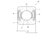
- FIG. 1 is a cross-sectional view schematically showing part of a rolling bearing according to an embodiment of the invention.
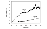
- FIG. 2 is a graph showing bearing vibrations in the rolling device of the first embodiment in comparison with those of the comparative example, where the vertical axis represents vibration acceleration and the horizontal axis represents test time.
- FIG. 3 is a graph showing bearing vibrations in the rolling device of the second embodiment in comparison with those of the comparative example, where the vertical axis is the vibration acceleration and the horizontal axis is the test time.
- FIG. 1 is a cross-sectional view schematically showing part of a rolling bearing according to an embodiment of the invention.
- a rolling bearing 10 according to the present embodiment includes an outer ring (first member) 1 having an outer ring raceway surface (first raceway surface) 1a on its inner peripheral surface, and a , and an inner ring (second member) having an inner ring raceway surface (second raceway surface) 3a facing the outer ring raceway surface 1a.
- a plurality of rolling elements (balls) 5 are rollably incorporated between the outer ring raceway surface 1a and the inner ring raceway surface 3a.
- Cages 7 made of synthetic resin are arranged at approximately equal intervals in the circumferential direction.
- the internal space of the rolling bearing 10 is supplied with a lubricant (not shown) that maintains good lubricity between the rolling elements 5 and the outer ring raceway surface 1a and the inner ring raceway surface 3a.
- Seals (sealing members) 9 are incorporated on both end face sides in the direction to seal the inner space of the bearing.
- the present embodiment provides a rolling device that includes a first member, a second member, and a plurality of rolling elements that are rotatably incorporated between the first member and the second member. It relates to improvement of rolling elements.
- a deep groove ball bearing can be exemplified as one embodiment of the rolling device according to the present embodiment.
- the materials of the rolling elements 5, the outer ring 1 and the inner ring 3, and the lubricant (grease) of the rolling bearing 10 according to the present embodiment will be described in more detail below.
- the rolling elements 5 are made of stainless steel, and among stainless steels, for example, martensitic stainless steel having high hardness is assumed.
- As the grease Li soap grease, urea grease, fluorine grease, etc., which are used for rolling bearings, can be suitably used.
- Conductive grease containing a conductive substance such as carbon black in the grease can also be used.
- the outer ring 1 and the inner ring 3 are made of SUJ2 (high carbon bearing steel) or the like.
- a deep groove ball bearing was described as one embodiment of the rolling device of the present invention, but rolling between the first member and the second member and between the first member and the second member It is a rolling device including a plurality of freely incorporated rolling elements, and the rolling elements are not limited to this embodiment as long as they are made of stainless steel.
- first member and a second annular bearing ring (second member) that are arranged to face each other in a relatively rotatable manner, and the first bearing ring and the second bearing ring an annular retainer having a plurality of pockets disposed between the ring and circumferentially spaced apart from each other; and cylindrical rollers (rolling elements) housed in the pockets of the retainer.
- first member and a second annular bearing ring (second member) that are arranged to face each other in a relatively rotatable manner
- the first bearing ring and the second bearing ring an annular retainer having a plurality of pockets disposed between the ring and circumferentially spaced apart from each other; and cylindrical rollers (rolling elements) housed in the pockets of the retainer.
- cylindrical rollers rolling elements housed in the pockets of the retainer.
- It may be a thrust cylindrical roller bearing or the like.
- a linear guide device (linear motion device) including a guide rail (first member) and a slider (second member) slidably mounted on the guide rail via a plurality of rolling elements, etc. may be
- a rolling bearing including: a retainer that retains the balls so that they can roll; a sealing member that seals between the outer ring and the inner ring; and grease that is arranged in a bearing internal space sealed by the sealing member.
- the rolling device of the first embodiment since stainless steel is used for the rolling elements, it is possible to suppress an increase in bearing vibration due to electrolytic corrosion at low cost.
- the rolling elements 5 are made of stainless steel, and for example, SUS420J2 steel, which is 13Cr stainless steel, can be used. Since the rolling elements 5 are made of stainless steel, a passivation film is formed on the surface of the rolling elements 5 . In this embodiment, since the surface roughness of the rolling elements 5 is controlled to be a predetermined value or less, the passivation film on the surface of the rolling elements 5 is uniform and good with few defects. There is Due to the presence of such a passive film, damage to the raceway surfaces 1a, 3a and the surface of the rolling element 5 can be reduced, and as a result, the acoustic characteristics of the rolling bearing can be maintained.
- the rolling elements 5 and the raceway surfaces 1a and 3a may be made of the same steel type, but are preferably made of different steel types. Different steel types may have different surface compositions (surface states).
- the rolling elements 5 and the raceway surfaces 1a and 3a which have different surface compositions, can be realized by different heat treatment conditions and passivation treatment conditions even when the same material is used.
- the surface compositions of the rolling elements 5 can be made different from those of the outer ring 1 and the inner ring 3, even when the rolling elements 5 and the raceway surfaces 1a and 3a come into metallic contact, adhesion of the mating material to each surface is prevented. can be suppressed and the surface roughness can be maintained satisfactorily.
- SUJ2 steel As the outer ring 1 and the inner ring 3, SUJ2 steel, SUS420J2 steel which is 13Cr stainless steel, or the like can be used. However, it is preferable to use normal bearing steel (SUJ2 steel). If SUJ2 steel material is used for the outer ring 1 and the inner ring 3, it is relatively easy to process the respective raceway surfaces 1a and 3a to the desired surface roughness.
- Electrolytic corrosion is caused by electrical discharge or current between the rolling elements 5 and the outer ring 1 and inner ring 3 . Electricity is generated in a state of metal contact, and as described above, according to the rolling bearing according to the present embodiment, since the passivation film on the surface of the rolling element 5 has insulating properties, even when metal contact is considered to be able to block current flow.
- the inventors of the present application have found that when the surface roughness Ra of the rolling elements 5 is 0.01 ⁇ m or less, a favorable passive film is formed on the surfaces of the rolling elements 5, which is uniform and has few defects. It was found that the occurrence of phagocytosis can be suppressed. Although the mechanism by which the surface roughness Ra suppresses the occurrence of electrolytic corrosion is not clear, the presence of a good passivation film with few defects makes the space between the rolling elements 5 and the raceway surfaces 1a and 3a like a capacitor. This is thought to be due to the fact that even if electricity is generated, the electricity flows slowly between the two.
- the surface roughness Ra of the rolling elements 5 is greater than 0.01 ⁇ m, the surface roughness increases, and defects may occur in the insulating passive film. It is conceivable that strong electricity locally flows between the raceway surfaces 1a and 3a and causes electrolytic corrosion. As a result of progress of electrolytic corrosion in this manner, bearing vibration increases and acoustic characteristics deteriorate.
- the surface roughness Ra is 0.01 ⁇ m or less, and the rolling elements 5 having a smaller curvature are softer than the raceway surfaces 1a and 3a and are easily deformable. It is considered that it is possible to prevent a large current from flowing in a concentrated manner. As a result, an increase in bearing vibration due to electrolytic corrosion can be suppressed, and excellent acoustic characteristics can be obtained.
- the surface roughness Ra of the rolling elements 5 is set to 0.01 ⁇ m or less, preferably 0.008 ⁇ m or less, and more preferably 0.006 ⁇ m or less.
- the surface roughness Ra of the rolling elements 5 is set to 0.01 ⁇ m or less, preferably 0.008 ⁇ m or less, and more preferably 0.006 ⁇ m or less.
- the surface roughness Ra of the outer ring raceway surface 1a and the inner ring raceway surface 3a is preferably 0.03 ⁇ m or less, more preferably 0.015 ⁇ m or less.
- the rolling elements are not limited to spheres, and may be rollers. Therefore, even in the case of rollers, it is preferable to control the surface roughness Ra within the above range.
- the rolling elements 5 and the raceway surfaces 1a and 3a preferably have different surface compositions. It may be solid, equivalent, or rigid. If the absolute value of the difference in Rockwell hardness between the rolling elements 5 and the raceway surfaces 1a and 3a is 4HRC or less, mutual wear can be prevented. Therefore, the absolute value of the difference in Rockwell hardness between the rolling elements 5 and the raceway surfaces 1a, 3a is preferably 4HRC or less.
- the minimum absolute value of the difference in Rockwell hardness between the rolling elements 5 and the raceway surfaces 1a and 3a is not particularly limited. The absolute value of the difference is preferably 1 HRC or more, more preferably 2 HRC or more.
- the surface hardness of the rolling elements 5 softer than the hardness of the raceway surfaces 1a and 3a.
- the hardness of the surface of the rolling element 5 softer than that of the raceway surfaces 1a and 3a
- the rolling element 5 side i. The higher the curvature, the more deformation (follows the shape of the other side). Therefore, when the rolling elements 5 and the raceway surfaces 1a and 3a come into metallic contact, they can be brought into contact with less damage.
- the hardness of the outer ring 1 and inner ring 3 made of SUJ2 steel is usually 61 HRC or more and 64 HRC or less, so the hardness of the stainless steel rolling elements 5 is preferably 56 HRC or more and 63 HRC or less.
- SUS440C steel which is 18Cr stainless steel
- SUS420J2 steel which is 13Cr stainless steel
- the lubricant (lubricating grease) supplied between the outer ring raceway surface 1a and the inner ring raceway surface 3a and the rolling elements 5 is not particularly limited.
- the lubricant Li soap grease, urea grease, fluorine grease, etc., which are used in rolling bearings, can be suitably used, and conductive grease containing a conductive substance such as carbon black in the grease can also be used. .
- the oil film thickness of the lubricant in order to prevent electrolytic corrosion.
- the oil film thickness can be set thinner than before.
- the kinematic viscosity of the lubricant at 40° C. is preferably 50 mm 2 /s or less.
- the rolling bearing according to the present embodiment can suppress the occurrence of electrolytic corrosion even when using a lubricant with such a low kinematic viscosity.
- the kinematic viscosity of the lubricant at 40° C. is more preferably 30 mm 2 /s or less, even more preferably 20 mm 2 /s or less.
- the rolling element having a Cr content of 16.0 to 18.0% by mass and the rolling element in the second embodiment having a Cr content of 10.0 to 15.0% by mass are both Compared to conventional rolling elements, it is possible to suppress an increase in bearing vibration due to electrolytic corrosion and obtain excellent acoustic characteristics. In particular, when electrolytic corrosion is assumed to occur but does not actually occur, or when the conditions are such that electrolytic corrosion is unlikely to occur, the rolling element in the second embodiment is superior. Acoustic performance can be obtained.
- the rolling bearing according to the present embodiment can reduce damage caused by electrolytic corrosion due to leakage current that tends to occur in inverter control. , blower motors and the like.
- the first and second embodiments of the present invention will be described in detail below with reference to invention examples and comparative examples, but the present invention is not limited to these.
- the first example shown below is an example showing the effects of the first embodiment
- the second example is an example showing the effects of the second embodiment.
- each rolling element was incorporated into a rolling bearing (deep groove ball bearing) including inner and outer rings and a plastic retainer of a single row deep groove ball bearing (inner diameter ⁇ 8 mm, outer diameter ⁇ 22 mm, width 7 mm) made by SUJ2.
- ester oil having a base oil viscosity of 24 cSt at 40° C. and Li soap as a thickener were used.
- Test condition Axial load: 50N Bearing rotation speed: 2000 min -1 Test time: 120 hours A resistor was inserted in series with the bearing, and a DC voltage of 30 V was applied so that the maximum current flowing through the bearing was 30 mA. Bearing vibration was measured using an accelerometer.
- a rolling bearing was prepared as follows. First, as test balls, a ball (LNS125 ball) made of LNS125 steel material, which is 13Cr stainless steel, and a ball (SUJ2 ball) made of SUJ2 steel material having a size of 5/32 were prepared.
- the LNS125 steel material is a 13Cr stainless steel containing 10.0 to 15.0% by mass of Cr, and the ball made of SUJ2 steel contains 1.3 to 1.6% by mass of Cr. It is something to do.
- prepare an outer ring and an inner ring of a single-row deep groove ball bearing (inner diameter: 8 mm, outer diameter: 22 mm, width: 7 mm), prepare a plastic cage, , incorporated balls and cages.
- the outer ring and inner ring were made of SUJ2 steel. Also, a lubricant was supplied to the inside of the bearing. As the lubricant, a grease containing an ester oil having a kinematic viscosity of 24 mm 2 /s at 40° C. as a base oil and a Li soap as a thickener was used.
- Table 1 below shows the steel grade, surface roughness, and Rockwell hardness of the rolling elements and raceway surfaces of the outer and inner rings.
- FIG. 2 is a graph showing the state of bearing vibration when the vertical axis is the vibration acceleration and the horizontal axis is the test time.
- the vibration acceleration increased significantly as the test time lengthened. It is believed that this is because a localized strong current that causes electrolytic corrosion was generated, which damaged the raceway surface and the surfaces of the rolling elements.
- the vibration acceleration was large even when the test time was long. did not rise. That is, although electrolytic corrosion occurred, damage was reduced, and a rolling bearing with excellent acoustic characteristics was obtained.
- the Anderon value of the rolling element using the ball of the first embodiment was 1.0 in the medium band and 1.1 in the high band.
- the Anderon value of the rolling element using the ball of the second embodiment was 0.4 in the medium band and 0.5 in the high band.
Landscapes
- Engineering & Computer Science (AREA)
- General Engineering & Computer Science (AREA)
- Mechanical Engineering (AREA)
- Rolling Contact Bearings (AREA)
Abstract
Description
この電位差が絶縁破壊電圧を超えて、内輪、外輪と転動体との間で放電が発生すると、軌道面及び転動体の表面が局所的に数1000℃程度に至る高温となり、これらの表面が溶融して、損傷(電食)することがある。
また、放電が多数発生すると、軌道面や転動体の表面の損傷(電食)が激しくなり、軸受の音響(振動)が上昇してしまうといった問題がある。
また、軸受を絶縁する方法としては、特許文献2に開示のように、外輪外径面にセラミック被膜を溶射する方法や、特許文献3に開示のように、セラミックの転動体(玉)を用いる方法などが提案されている。
そのため、グリースの導電性が経時的に低下してしまい、電食を防止する効果を長期にわたり持続することが困難である場合もある。
また、特許文献2及び3に記載の方法によれば、電食の発生を防止することに効果的ではあるものの、軌道輪と転動体が軸受鋼で構成される軸受と比較して、軸受の製造コストが相当に高くなってしまうといった問題点がある。
しかしながら、上記特許文献1~4に記載の転がり軸受は、いずれも、要求される音響特性を十分に満足することが困難である場合が多い。
前記第1の部材に組み付けられ、前記第1の軌道面に対向する第2の軌道面を有する第2の部材と、
前記第1の軌道面と前記第2の軌道面との間に転動自在に組み込まれる複数個の転動体と、を備え、
前記転動体はステンレス鋼で構成されており、
前記転動体の表面粗さRaが0.01μm以下であることを特徴とする転がり軸受。
前記転動体の表面の硬さは、56HRC以上63HRC以下であることを特徴とする、[3]又は[4]に記載の転がり軸受。
40℃における前記潤滑剤の動粘度は、50mm2/s以下であることを特徴とする、[1]~[5]のいずれか1つに記載の転がり軸受。
[転がり軸受]
図1は、本発明の実施形態に係る転がり軸受の一部を模式的に示す断面図である。
図1に示すように、本実施形態に係る転がり軸受10は、内周面に外輪軌道面(第1の軌道面)1aを有する外輪(第1の部材)1と、外輪1に組み付けられて、外輪軌道面1aに対向する内輪軌道面(第2の軌道面)3aを有する内輪(第2の部材)とを有する。
また、外輪軌道面1aと内輪軌道面3aとの間には、複数個の転動体(玉)5が転動自在に組み込まれているとともに、複数個の転動体5の間には、これらを円周方向に略等間隔に保持する合成樹脂製の保持器7が配置されている。
さらに、転がり軸受10の内部空間には、転動体5と外輪軌道面1a及び内輪軌道面3aとの潤滑性を良好に保つ潤滑剤(図示せず)が供給されており、転がり軸受10の軸方向における両端面側には、軸受内部空間を密封するため密封シール(密封部材)9が組み込まれている。
以下、本実施形態に係る転がり軸受10の転動体5、外輪1及び内輪3の材質、並びに潤滑剤(グリース)について、さらに詳細に説明する。
転動体5は、ステンレス鋼からなり、例えば、ステンレス鋼の中でも高硬度のマルテンサイト系ステンレス鋼などが想定される。また、グリースには、転がり軸受に用いられるLi石けんグリースやウレアグリース、フッ素グリース等が好適に使用でき、またグリース中にカーボンブラック等の導電性物質を含む導電性グリースも使用可能である。外輪1や内輪3はSUJ2(高炭素軸受鋼)などで構成される。
例えば、相対回転可能に対向配置された円環状の第1の軌道輪(第1の部材)及び第2の軌道輪(第2の部材)と、そして、第1の軌道輪と第2の軌道輪との間に配置され、円周方向に互いに間隔をおいて形成された複数のポケットを有する環状の保持器と、保持器のポケット内に収容された円筒ころ(転動体)と、を備えたスラスト円筒ころ軸受等であってもよい。
また、案内レール(第1の部材)と、案内レールに複数の転動体を介してスライド移動可能に跨設されるスライダ(第2の部材)と、を含むリニアガイド装置(直動装置)等であってもよい。
上記転動体はステンレス鋼で構成されていることを特徴とする転動装置。
上記玉を転動自在に保持する保持器と、上記外輪と上記内輪との間をシールする密封部材と、上記密封部材によって密封された軸受内部空間に配されるグリースと、を含む転がり軸受であることを特徴とする(1)又は(2)に記載の転動装置。
次に、第2実施形態について説明する。第2実施形態において、転がり軸受の構成は上記第1実施形態と同様である。したがって、図1を参照して、第2実施形態に係る転がり軸受10の転動体5、外輪1及び内輪3の材質、転動体5、外輪軌道面1a及び内輪軌道面3aの表面粗さ、硬さ、並びに潤滑剤について、さらに詳細に説明する。
本実施形態において、転動体5は、ステンレス鋼で構成されており、例えば、13Crステンレス鋼であるSUS420J2鋼材等を使用することができる。
転動体5がステンレス鋼により構成されているため、転動体5の表面には、不働態皮膜が形成される。本実施形態においては、転動体5の表面粗さを所定の値以下となるように制御しているため、転動体5の表面における不働態皮膜は、均一で欠陥が少ない良好なものとなっている。このような不働態皮膜の存在により、軌道面1a、3a及び転動体5の表面の損傷を低減することができ、その結果、転がり軸受の音響特性を維持することができる。
具体的に、外輪1及び内輪3としては、SUJ2鋼材、13Crステンレス鋼であるSUS420J2鋼材等を使用することができる。ただし、通常の軸受鋼(SUJ2鋼材)を用いることが好ましい。外輪1及び内輪3としてSUJ2鋼材を使用すれば、それぞれの軌道面1a、3aを所望の表面粗さに加工することが比較的容易である。
<外輪軌道面1a及び内輪軌道面3aの表面粗さRa:0.03μm以下>
電食は、転動体5と、外輪1及び内輪3との間での放電か通電により発生する。通電は金属接触状態で生ずるものであり、上述のとおり、本実施形態に係る転がり軸受によると、転動体5の表面の不働態皮膜が絶縁性を有しているため、金属接触した場合でもある程度は通電を阻止することができると考えられる。
一方、本実施形態においては、表面粗さRaが0.01μm以下であり、かつ、より小さい曲率を有する転動体5が軌道面1a、3aより柔らかく、変形しやすい構成であるため、局所的に大電流が集中して流れることを防止できると考えられる。その結果、電食による軸受振動の上昇を抑制することができ、優れた音響特性を得ることができる。
ステンレス転動体が鋼球である場合に、転がり軸受における鋼球の形状及び表面粗さは、JIS B 1501:2009において、種々の等級で規定されている。本実施形態においては、鋼球の等級がG3を上回るものであることが好ましい。
軌道面1a、3aの表面粗さRaは、具体的には、0.03μm以下であることが好ましく、0.015μm以下とすることがより好ましい。
なお、転動体は球体に限定されず、ころであってもよい。したがって、ころの場合であっても、上記表面粗さRaの範囲に制御することが好ましい。
<転動体5の表面の硬さ:56HRC以上63HRC以下>
上述のとおり、転動体5と、軌道面1a、3aとは、互いに異なる表面組成を有することが好ましいが、軌道面1a、3aの硬さは、転動体5の表面の硬さよりも柔らかいものであっても、同等か、あるいは硬いものであってもよい。
なお、転動体5と、軌道面1a、3aとの間のロックウェル硬さの差の絶対値が4HRC以下であると、互いに摩耗することを防止することができる。したがって、転動体5と、軌道面1a、3aとの間のロックウェル硬さの差の絶対値は、4HRC以下であることが好ましい。
転動体5と、軌道面1a、3aとの間のロックウェル硬さの差の絶対値における最小値は特に限定しないが、硬度差を設けることによる十分な効果を得るため、ロックウェル硬さの差の絶対値は1HRC以上であることが好ましく、2HRC以上であることがより好ましい。
本実施形態において、外輪軌道面1a及び内輪軌道面3aと、転動体5との間に供給される潤滑剤(潤滑グリース)については、特に限定されない。
例えば、潤滑剤としては、転がり軸受に用いられるLi石けんグリースやウレアグリース、フッ素グリース等が好適に使用でき、またグリース中にカーボンブラック等の導電性物質を含む導電性グリースを使用することができる。
電食による軸受振動の上昇の抑制に関して、本実施形態の転がり軸受における効果を確認するため、軸受に通電させた状態での軸受振動の経時変化を調査する試験を行った。
そして、それぞれの転動体を、SUJ2製の単列深溝玉軸受(内径φ8mm、外径φ22mm、幅7mm)の内外輪、プラスチック製保持器を含む転がり軸受(深溝玉軸受)に組み込んだ。
また、軸受内部に封入するグリースには、基油が40℃における基油粘度が24cStであるエステル油、増ちょう剤がLi石けんのグリースを用いた。
アキシャル荷重:50N
軸受回転数:2000min-1
試験時間:120時間
軸受と直列に抵抗を挿入し、軸受に流れる電流が最大で30mAになるように、30Vの直流電圧を印加した。
軸受振動は加速度ピックアップを用いて測定した。
結果を図2に示す。図2に示すように、SUJ2(高炭素軸受鋼)ボールを用いた比較例の転がり軸受は試験中に軸受振動が上昇しているが、SUS440C(ステンレス)ボールを用いた本実施形態の転がり軸受の軸受振動は上昇がみられない。
[軸受振動試験]
本発明に係る転がり軸受における電食抑制の効果を確認するため、13Cr系ステンレス製(LNS125)の転動体(玉)と軸受(外輪及び内輪)に通電させた状態で、軸受振動の経時変化を測定する軸受振動試験を行った。
以下のようにして、転がり軸受を準備した。
まず、試験用の玉として、サイズが5/32の13Cr系ステンレス鋼であるLNS125鋼材からなる玉(LNS125球)と、SUJ2鋼材からなる玉(SUJ2球)を準備した。なお、LNS125鋼材は、13Cr系ステンレス鋼であって、Crを10.0~15.0質量%含有するものであり、SUJ2鋼材からなる玉は、Crを1.3~1.6質量%含有するものである。
次に、単列深溝玉軸受(内径:8mm、外径:22mm、幅:7mm)の外輪と内輪を準備するとともに、プラスチック製保持器を準備し、外輪軌道面と内輪軌道面との間に、玉と保持器を組み込んだ。外輪及び内輪は、SUJ2鋼材からなるものを使用した。
また、軸受内部に、潤滑剤を供給した。潤滑剤としては、40℃における動粘度が24mm2/sであるエステル油を基油とし、Li石けんを増ちょう剤としたグリースを用いた。

作製した転がり軸受を用いて、軸受振動試験を実施した。
まず、軸受及び外部抵抗が直列となるように接続し、軸受に流れる電流が最大で30mAになるように、30Vの直流電圧を印加した。その後、加速度ピックアップを用いて、軸受振動を測定した。
試験条件は以下のとおりとした。
アキシャル荷重:50N
軸受回転数:2000min-1
試験時間:120時間
図2は、縦軸を振動加速度とし、横軸を試験時間とした場合の、軸受振動の様子を示すグラフである。
図2に示すように、転動体として、SUJ2球を用いた転がり軸受(比較例)においては、試験時間が長くなるにしたがって、振動加速度が大きく上昇した。これは、電食の原因となる局所的な強い電流が発生し、これにより、軌道面や転動体の表面が損傷したからであると考えられる。
一方、転動体として、表面粗さRaが0.001μmであるLNS125球を使用した本発明に係る転がり軸受(発明例)においては、試験時間が長くなった場合であっても、振動加速度は大きく上昇しなかった。すなわち、電食は発生するものの、損傷が小さくなり、音響特性が優れた転がり軸受を得ることができた。
上記第1実施例において使用した玉(SUS440Cからなるステンレスボール)を複数個準備するとともに、上記第2実施例において使用した玉(13Cr系ステンレス鋼からなるLNS125球)を複数個準備し、玉の種類に対する音響振動(アンデロン値)を比較した。具体的には、同等の精度に仕上げた軸受に上記玉を組み込み、公知の測定装置によりミディアムバンド及びハイバンドを測定し、n=6~8として平均値を算出した。
上記第1実施例の玉を使用した転動体については、アンデロン値のミディアムバンドが1.0、ハイバンドが1.1であった。これに対して、上記第2実施例の玉を使用した転動体については、アンデロン値のミディアムバンドが0.4、ハイバンドが0.5であった。これらの結果から、Crを10.0~15.0質量%含有するステンレス鋼からなる玉を使用した転動体の方が、電食発生の抑制効果と優れた音響特性との両立を優れたバランスで実現することができた。
1a 外輪軌道面
3 内輪
3a 内輪軌道面
5 転動体
7 保持器
10 転がり軸受
Claims (6)
- 第1の軌道面を有する第1の部材と、
前記第1の部材に組み付けられ、前記第1の軌道面に対向する第2の軌道面を有する第2の部材と、
前記第1の軌道面と前記第2の軌道面との間に転動自在に組み込まれる複数個の転動体と、を備え、
前記転動体はステンレス鋼で構成されており、
前記転動体の表面粗さRaが0.01μm以下であることを特徴とする転がり軸受。 - 前記第1の軌道面及び前記第2の軌道面の表面粗さRaは、いずれも0.03μm以下であることを特徴とする、請求項1に記載の転がり軸受。
- 前記転動体と、前記第1の軌道面及び前記第2の軌道面とは、互いに異なる表面組成を有することを特徴とする、請求項2に記載の転がり軸受。
- 前記第1の軌道面及び前記第2の軌道面の硬さと、前記転動体の表面の硬さとの差の絶対値は、4HRC以下であることを特徴とする、請求項3に記載の転がり軸受。
- 前記第1の軌道面及び前記第2の軌道面の硬さは、58HRC以上64HRC以下であり、
前記転動体の表面の硬さは、56HRC以上63HRC以下であることを特徴とする、請求項4に記載の転がり軸受。 - 前記第1の軌道面及び前記第2の軌道面と、前記転動体との間に、潤滑剤が供給されており、
40℃における前記潤滑剤の動粘度は、50mm2/s以下であることを特徴とする、請求項5に記載の転がり軸受。
Priority Applications (3)
| Application Number | Priority Date | Filing Date | Title |
|---|---|---|---|
| EP22858110.4A EP4390161A1 (en) | 2021-08-20 | 2022-04-12 | Rolling bearing |
| JP2022547301A JP7231117B1 (ja) | 2021-08-20 | 2022-04-12 | 転がり軸受 |
| CN202280056799.9A CN117859012A (zh) | 2021-08-20 | 2022-04-12 | 滚动轴承 |
Applications Claiming Priority (2)
| Application Number | Priority Date | Filing Date | Title |
|---|---|---|---|
| JP2021-135064 | 2021-08-20 | ||
| JP2021135064 | 2021-08-20 |
Publications (1)
| Publication Number | Publication Date |
|---|---|
| WO2023021786A1 true WO2023021786A1 (ja) | 2023-02-23 |
Family
ID=85240367
Family Applications (1)
| Application Number | Title | Priority Date | Filing Date |
|---|---|---|---|
| PCT/JP2022/017648 WO2023021786A1 (ja) | 2021-08-20 | 2022-04-12 | 転がり軸受 |
Country Status (4)
| Country | Link |
|---|---|
| EP (1) | EP4390161A1 (ja) |
| JP (1) | JP7231117B1 (ja) |
| CN (1) | CN117859012A (ja) |
| WO (1) | WO2023021786A1 (ja) |
Citations (9)
| Publication number | Priority date | Publication date | Assignee | Title |
|---|---|---|---|---|
| JP2001304150A (ja) | 2000-02-18 | 2001-10-31 | Hitachi Ltd | スクロール圧縮機 |
| JP2002339976A (ja) * | 2001-05-16 | 2002-11-27 | Koyo Seiko Co Ltd | 転がり軸受 |
| JP2007056912A (ja) * | 2005-08-22 | 2007-03-08 | Nsk Ltd | 小径転がり軸受 |
| JP2008069923A (ja) | 2006-09-15 | 2008-03-27 | Ntn Corp | モータ用電食防止転がり軸受 |
| JP2009097658A (ja) | 2007-10-18 | 2009-05-07 | Ntn Corp | 転動部材および転がり軸受 |
| JP2009197114A (ja) | 2008-02-21 | 2009-09-03 | Ntn Corp | 導電性グリース、導電性転がり軸受、該軸受を用いた画像形成装置および定着装置 |
| JP2016094990A (ja) * | 2014-11-14 | 2016-05-26 | Ntn株式会社 | 転動装置 |
| JP2020173046A (ja) | 2019-04-09 | 2020-10-22 | パナソニックIpマネジメント株式会社 | 液体微細化装置 |
| JP2021135064A (ja) | 2020-02-21 | 2021-09-13 | リオン株式会社 | 加速度測定装置および加速度測定方法 |
-
2022
- 2022-04-12 CN CN202280056799.9A patent/CN117859012A/zh active Pending
- 2022-04-12 WO PCT/JP2022/017648 patent/WO2023021786A1/ja active Application Filing
- 2022-04-12 EP EP22858110.4A patent/EP4390161A1/en active Pending
- 2022-04-12 JP JP2022547301A patent/JP7231117B1/ja active Active
Patent Citations (9)
| Publication number | Priority date | Publication date | Assignee | Title |
|---|---|---|---|---|
| JP2001304150A (ja) | 2000-02-18 | 2001-10-31 | Hitachi Ltd | スクロール圧縮機 |
| JP2002339976A (ja) * | 2001-05-16 | 2002-11-27 | Koyo Seiko Co Ltd | 転がり軸受 |
| JP2007056912A (ja) * | 2005-08-22 | 2007-03-08 | Nsk Ltd | 小径転がり軸受 |
| JP2008069923A (ja) | 2006-09-15 | 2008-03-27 | Ntn Corp | モータ用電食防止転がり軸受 |
| JP2009097658A (ja) | 2007-10-18 | 2009-05-07 | Ntn Corp | 転動部材および転がり軸受 |
| JP2009197114A (ja) | 2008-02-21 | 2009-09-03 | Ntn Corp | 導電性グリース、導電性転がり軸受、該軸受を用いた画像形成装置および定着装置 |
| JP2016094990A (ja) * | 2014-11-14 | 2016-05-26 | Ntn株式会社 | 転動装置 |
| JP2020173046A (ja) | 2019-04-09 | 2020-10-22 | パナソニックIpマネジメント株式会社 | 液体微細化装置 |
| JP2021135064A (ja) | 2020-02-21 | 2021-09-13 | リオン株式会社 | 加速度測定装置および加速度測定方法 |
Also Published As
| Publication number | Publication date |
|---|---|
| JP7231117B1 (ja) | 2023-03-01 |
| CN117859012A (zh) | 2024-04-09 |
| JPWO2023021786A1 (ja) | 2023-02-23 |
| EP4390161A1 (en) | 2024-06-26 |
Similar Documents
| Publication | Publication Date | Title |
|---|---|---|
| EP2287481B1 (en) | Retainer, deep groove ball bearing, and bearing with seal | |
| JP2007107588A (ja) | 転がり軸受 | |
| JP2006250316A (ja) | 転動装置 | |
| WO2023021786A1 (ja) | 転がり軸受 | |
| JPH09291942A (ja) | ラジアル転がり軸受 | |
| JP2008180374A (ja) | 転がり軸受 | |
| JP2014029198A (ja) | 深溝玉軸受 | |
| JP2007139014A (ja) | アンギュラ玉軸受およびナット回転型ボールねじ装置 | |
| CN101975226A (zh) | 自润滑滚动轴承 | |
| JP2012219995A (ja) | 転がり軸受およびその製造方法 | |
| KR20240038746A (ko) | 볼 베어링 | |
| JP2006250313A (ja) | 転動装置 | |
| JP2009197894A (ja) | 転がり軸受、及びモータ | |
| JPH04370411A (ja) | ハイブリッド軸受 | |
| JP2008019965A (ja) | 遊星歯車装置及び転がり軸受 | |
| JPH084773A (ja) | 固体潤滑転がり軸受 | |
| JP2022064421A (ja) | 転動装置 | |
| JP2001248708A (ja) | 転動装置 | |
| JP2006250324A (ja) | 保持器 | |
| JP2012172812A (ja) | 転がり軸受 | |
| JP4269809B2 (ja) | 自動調心ころ軸受 | |
| JP2004076928A (ja) | 転がり軸受用合成樹脂製保持器及び転がり軸受 | |
| JP2012031989A (ja) | 転がり軸受及びそれを備えたダンパー付きプーリー | |
| JP4277521B2 (ja) | テンタークリップ用転がり軸受 | |
| JP2007255554A (ja) | スラストころ軸受 |
Legal Events
| Date | Code | Title | Description |
|---|---|---|---|
| ENP | Entry into the national phase |
Ref document number: 2022547301 Country of ref document: JP Kind code of ref document: A |
|
| 121 | Ep: the epo has been informed by wipo that ep was designated in this application |
Ref document number: 22858110 Country of ref document: EP Kind code of ref document: A1 |
|
| WWE | Wipo information: entry into national phase |
Ref document number: 202280056799.9 Country of ref document: CN |
|
| WWE | Wipo information: entry into national phase |
Ref document number: 2022858110 Country of ref document: EP |
|
| NENP | Non-entry into the national phase |
Ref country code: DE |
|
| ENP | Entry into the national phase |
Ref document number: 2022858110 Country of ref document: EP Effective date: 20240320 |