WO2023013435A1 - 基板処理方法および基板処理装置 - Google Patents
基板処理方法および基板処理装置 Download PDFInfo
- Publication number
- WO2023013435A1 WO2023013435A1 PCT/JP2022/028434 JP2022028434W WO2023013435A1 WO 2023013435 A1 WO2023013435 A1 WO 2023013435A1 JP 2022028434 W JP2022028434 W JP 2022028434W WO 2023013435 A1 WO2023013435 A1 WO 2023013435A1
- Authority
- WO
- WIPO (PCT)
- Prior art keywords
- processing
- pressure
- substrate
- fluid
- supply line
- Prior art date
- Legal status (The legal status is an assumption and is not a legal conclusion. Google has not performed a legal analysis and makes no representation as to the accuracy of the status listed.)
- Ceased
Links
Images






Classifications
-
- H—ELECTRICITY
- H10—SEMICONDUCTOR DEVICES; ELECTRIC SOLID-STATE DEVICES NOT OTHERWISE PROVIDED FOR
- H10P—GENERIC PROCESSES OR APPARATUS FOR THE MANUFACTURE OR TREATMENT OF DEVICES COVERED BY CLASS H10
- H10P72/00—Handling or holding of wafers, substrates or devices during manufacture or treatment thereof
- H10P72/04—Apparatus for manufacture or treatment
- H10P72/0402—Apparatus for fluid treatment
- H10P72/0406—Apparatus for fluid treatment for cleaning followed by drying, rinsing, stripping, blasting or the like
- H10P72/0411—Apparatus for fluid treatment for cleaning followed by drying, rinsing, stripping, blasting or the like for wet cleaning or washing
- H10P72/0416—Apparatus for fluid treatment for cleaning followed by drying, rinsing, stripping, blasting or the like for wet cleaning or washing with the semiconductor substrates being dipped in baths or vessels
-
- H—ELECTRICITY
- H10—SEMICONDUCTOR DEVICES; ELECTRIC SOLID-STATE DEVICES NOT OTHERWISE PROVIDED FOR
- H10P—GENERIC PROCESSES OR APPARATUS FOR THE MANUFACTURE OR TREATMENT OF DEVICES COVERED BY CLASS H10
- H10P52/00—Grinding, lapping or polishing of wafers, substrates or parts of devices
-
- H—ELECTRICITY
- H10—SEMICONDUCTOR DEVICES; ELECTRIC SOLID-STATE DEVICES NOT OTHERWISE PROVIDED FOR
- H10P—GENERIC PROCESSES OR APPARATUS FOR THE MANUFACTURE OR TREATMENT OF DEVICES COVERED BY CLASS H10
- H10P70/00—Cleaning of wafers, substrates or parts of devices
- H10P70/20—Cleaning during device manufacture
-
- H—ELECTRICITY
- H10—SEMICONDUCTOR DEVICES; ELECTRIC SOLID-STATE DEVICES NOT OTHERWISE PROVIDED FOR
- H10P—GENERIC PROCESSES OR APPARATUS FOR THE MANUFACTURE OR TREATMENT OF DEVICES COVERED BY CLASS H10
- H10P70/00—Cleaning of wafers, substrates or parts of devices
- H10P70/80—Cleaning only by supercritical fluids
-
- H—ELECTRICITY
- H10—SEMICONDUCTOR DEVICES; ELECTRIC SOLID-STATE DEVICES NOT OTHERWISE PROVIDED FOR
- H10P—GENERIC PROCESSES OR APPARATUS FOR THE MANUFACTURE OR TREATMENT OF DEVICES COVERED BY CLASS H10
- H10P72/00—Handling or holding of wafers, substrates or devices during manufacture or treatment thereof
- H10P72/04—Apparatus for manufacture or treatment
- H10P72/0402—Apparatus for fluid treatment
-
- H—ELECTRICITY
- H10—SEMICONDUCTOR DEVICES; ELECTRIC SOLID-STATE DEVICES NOT OTHERWISE PROVIDED FOR
- H10P—GENERIC PROCESSES OR APPARATUS FOR THE MANUFACTURE OR TREATMENT OF DEVICES COVERED BY CLASS H10
- H10P72/00—Handling or holding of wafers, substrates or devices during manufacture or treatment thereof
- H10P72/04—Apparatus for manufacture or treatment
- H10P72/0402—Apparatus for fluid treatment
- H10P72/0406—Apparatus for fluid treatment for cleaning followed by drying, rinsing, stripping, blasting or the like
-
- H—ELECTRICITY
- H10—SEMICONDUCTOR DEVICES; ELECTRIC SOLID-STATE DEVICES NOT OTHERWISE PROVIDED FOR
- H10P—GENERIC PROCESSES OR APPARATUS FOR THE MANUFACTURE OR TREATMENT OF DEVICES COVERED BY CLASS H10
- H10P72/00—Handling or holding of wafers, substrates or devices during manufacture or treatment thereof
- H10P72/04—Apparatus for manufacture or treatment
- H10P72/0402—Apparatus for fluid treatment
- H10P72/0406—Apparatus for fluid treatment for cleaning followed by drying, rinsing, stripping, blasting or the like
- H10P72/0408—Apparatus for fluid treatment for cleaning followed by drying, rinsing, stripping, blasting or the like for drying
Definitions
- the present disclosure relates to a substrate processing method and a substrate processing apparatus.
- a processing fluid in a supercritical state to which an additive has been added is placed in a processing vessel.
- Substrate processing with confinement over time is known (US Pat.
- the present disclosure provides a technology capable of stably confining a supercritical processing fluid in a processing container for a long period of time.
- a substrate processing method is a substrate processing method for a substrate processing apparatus that processes a substrate by bringing it into contact with a processing fluid in a supercritical state.
- the substrate processing apparatus includes a processing vessel, a main supply line, a discharge line, and a bypass line.
- the processing container has a processing space capable of accommodating the substrate.
- a main supply line supplies the process fluid to the process space.
- a discharge line has a first on-off valve and discharges the processing fluid from the processing space.
- the bypass line branches off from the main supply line at a branch point and merges at a junction downstream of the first on-off valve in the discharge line.
- a substrate processing method includes a pressurizing step and a holding step.
- the pressure in the processing space is increased to a given processing pressure by supplying the processing fluid from the main supply line to the processing space while the substrate is accommodated in the processing space.
- the pressure in the processing space is held at the processing pressure while allowing the processing fluid to flow through the bypass line with the first on-off valve closed.
- the processing fluid in the supercritical state can be stably confined in the processing container for a long period of time.
- FIG. 1 is a diagram showing a schematic configuration of a substrate processing system according to an embodiment.
- FIG. 2 is a cross-sectional view showing an example of the configuration of the supply processing unit according to the embodiment.
- FIG. 3 is an external perspective view showing an example of the configuration of the substrate processing unit according to the embodiment;
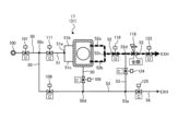
- FIG. 4 is a diagram illustrating an example of the configuration of supply lines and discharge lines connected to the substrate processing unit according to the embodiment;
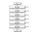
- FIG. 5 is a flowchart illustrating an example of the procedure of each process executed by the substrate processing unit according to the embodiment;
- FIG. 6 is a diagram showing an example of time change of the pressure in the processing space during the pressurizing process, the holding process, the circulation process, and the depressurizing process according to the embodiment.
- FIG. 1 is a diagram showing a schematic configuration of a substrate processing system according to an embodiment.
- FIG. 2 is a cross-sectional view showing an example of the configuration of the supply processing unit according to the embodiment.
- FIG. 3 is an external
- FIG. 7 is a diagram illustrating an operation example of boosting processing according to the embodiment.
- FIG. 8 is a diagram illustrating an operation example of holding processing according to the embodiment.
- FIG. 9 is a diagram illustrating an operation example of distribution processing according to the embodiment.
- FIG. 10 is a diagram illustrating an operation example of pressure reduction processing according to the embodiment.
- FIG. 11 is a diagram illustrating an operation example of pressure reduction processing according to the embodiment.
- FIG. 12 is a diagram illustrating an operation example of retention processing according to another embodiment.
- a processing fluid in a supercritical state to which an additive has been added is placed in a processing vessel.
- Substrate processing with confinement over time is known.
- FIG. 1 is a diagram showing a schematic configuration of a substrate processing system 1 according to an embodiment.
- the X-axis, Y-axis and Z-axis are defined to be orthogonal to each other, and the positive direction of the Z-axis is defined as the vertically upward direction.
- the substrate processing system 1 includes a loading/unloading station 2 and a processing station 3 .
- the substrate processing system 1 is an example of a substrate processing apparatus.
- the loading/unloading station 2 and the processing station 3 are provided adjacently.
- the loading/unloading station 2 includes a carrier placement section 11 and a transport section 12 .
- a plurality of carriers C accommodating a plurality of semiconductor wafers W (hereinafter referred to as “wafers W”) in a horizontal state are mounted on the carrier mounting portion 11 .
- Wafer W is an example of a substrate.
- the transport section 12 is provided adjacent to the carrier mounting section 11 and includes a substrate transport device 13 and a transfer section 14 therein.
- the substrate transfer device 13 includes a wafer holding mechanism that holds the wafer W. As shown in FIG. Further, the substrate transfer device 13 can move in the horizontal direction and the vertical direction and can rotate about the vertical axis. conduct.
- the processing station 3 is provided adjacent to the transport section 12 .
- the processing station 3 includes a transport section 15 , a plurality of supply processing units 16 and a plurality of substrate processing units 17 .
- the plurality of supply processing units 16 and the plurality of substrate processing units 17 are arranged side by side on both sides of the transport section 15 .
- the arrangement and the number of supply processing units 16 and substrate processing units 17 shown in FIG. 1 are examples, and are not limited to those illustrated.
- the transport unit 15 includes a substrate transport device 18 inside.
- the substrate transfer device 18 includes a wafer holding mechanism that holds the wafer W. As shown in FIG. Further, the substrate transfer device 18 is capable of horizontal and vertical movement and rotation about the vertical axis. The wafer W is transferred between
- the supply processing unit 16 performs a given additive supply processing on the wafer W transported by the substrate transport device 18 .
- a configuration example of the supply processing unit 16 will be described later.
- the substrate processing unit 17 performs given substrate processing on the wafer W supplied with the additive by the supply processing unit 16 .
- a configuration example of the substrate processing unit 17 will be described later.
- the substrate processing system 1 also includes a control device 4 .
- Control device 4 is, for example, a computer, and includes control section 19 and storage section 20 .
- the control unit 19 includes a microcomputer having a CPU (Central Processing Unit), ROM (Read Only Memory), RAM (Random Access Memory), input/output ports, and various circuits.
- the CPU of such a microcomputer reads out and executes a program stored in the ROM, thereby realizing the control described later.
- the program may be recorded in a computer-readable recording medium and installed in the storage unit 20 of the control device 4 from the recording medium.
- Examples of computer-readable recording media include hard disks (HD), flexible disks (FD), compact disks (CD), magnet optical disks (MO), and memory cards.
- the storage unit 20 is implemented, for example, by a semiconductor memory device such as a RAM or flash memory, or a storage device such as a hard disk or optical disk.
- the substrate transfer device 13 of the loading/unloading station 2 takes out the wafer W from the carrier C placed on the carrier platform 11, and receives the taken out wafer W. It is placed on the transfer section 14 .
- the wafer W placed on the transfer section 14 is taken out from the transfer section 14 by the substrate transfer device 18 of the processing station 3 and carried into the supply processing unit 16 .
- the wafer W loaded into the supply processing unit 16 is subjected to additive supply processing by the supply processing unit 16 and then unloaded from the supply processing unit 16 by the substrate transfer device 18 .
- the wafer W unloaded from the supply processing unit 16 is carried into the substrate processing unit 17 by the substrate transfer device 18 and subjected to substrate processing by the substrate processing unit 17 .
- the wafer W subjected to substrate processing by the substrate processing unit 17 is unloaded from the substrate processing unit 17 by the substrate transfer device 18 and placed on the transfer section 14 . Then, the processed wafer W placed on the transfer section 14 is returned to the carrier C on the carrier placement section 11 by the substrate transfer device 13 .
- FIG. 2 is a cross-sectional view showing an example of the configuration of the supply processing unit 16 according to the embodiment.
- the supply processing unit 16 is configured as a single-wafer type supply processing unit that supplies the additive A to the upper surface of the wafer W one by one, for example.
- the supply processing unit 16 holds a wafer W substantially horizontally by a wafer holding mechanism 25 arranged in an outer chamber 23 forming a processing space. , the wafer W is rotated.
- the supply processing unit 16 causes the nozzle arm 26 to enter above the rotating wafer W, and supplies the additive A from the nozzle 26 a provided at the tip of the nozzle arm 26 , so that the upper surface of the wafer W is Then, the additive supply process is performed.
- the additive A supplied in the additive supply process described above is, for example, a mixture of a low-valent alcohol (e.g., ethanol, methanol, IPA (isopropyl alcohol), etc.) and a liquid having a different polarity from the low-valent alcohol. Liquid. Moreover, the additive A is a liquid having a high affinity with CO 2 (carbon dioxide) used as a processing fluid.
- a low-valent alcohol e.g., ethanol, methanol, IPA (isopropyl alcohol), etc.
- IPA isopropyl alcohol
- Such additive A is mixed in a given ratio in advance and stored in the storage section 28 .
- the reservoir 28 has a tank 28a and a closed container 28b.
- the additive A mixed in advance at a given ratio is stored in the tank 28a.
- a stirring mechanism (not shown) or the like may be provided inside the tank 28a.
- the additive A in which a plurality of types of chemical solutions with different polarities are mixed, can be supplied to the wafer W in a well-mixed state.
- the sealed container 28b stores the tank 28a inside and separates the internal space in which the tank 28a is stored from the external space.
- control unit 19 (see FIG. 1) operates the nitrogen gas supply unit 27 to supply nitrogen gas to the inside of the tank 28a, thereby increasing the pressure inside the sealed container 28b.
- the additive A is supplied to the nozzle 26a through the additive supply passage 29a of the additive supply section 29 connected between the inside of the tank 28a and the nozzle 26a.
- the nitrogen gas supply unit 27 has a nitrogen gas supply source 27a, a nitrogen gas supply path 27b, a flow regulator 27c, and a filter 27d.
- the nitrogen gas supply source 27a is, for example, a tank that stores nitrogen gas.
- the nitrogen gas supply path 27b connects the nitrogen gas supply source 27a and the inside of the tank 28a, and supplies nitrogen gas from the nitrogen gas supply source 27a to the inside of the tank 28a.
- the flow rate regulator 27c is arranged in the nitrogen gas supply path 27b and adjusts the flow rate of nitrogen gas supplied to the inside of the tank 28a.
- the flow regulator 27c has an on-off valve, a flow control valve, a flow meter, and the like.
- the filter 27d filters nitrogen gas flowing through the nitrogen gas supply path 27b.
- the additive supply path 29a of the additive supply unit 29 is provided with a valve 29b.
- the controller 19 can control whether or not the additive A is supplied to the nozzle 26a by opening and closing the valve 29b.
- the additive A is supplied to the entire upper surface of the wafer W while rotating the wafer holding mechanism 25, and then the rotation of the wafer holding mechanism 25 is gently stopped.
- the wafer W is held by the wafer holding mechanism while the additive A is applied to the upper surface of the wafer W, in other words, the additive A liquid film is formed on the upper surface of the wafer W. 25 is transferred to the substrate transfer device 18 by a transfer mechanism (not shown). After that, the wafer W is unloaded from the supply processing unit 16 .
- the additive A overflowing from the wafer W is received by the outer chamber 23 and the inner cup 24 arranged in the outer chamber 23 .
- the additive A is discharged from a drain port 23 a provided at the bottom of the outer chamber 23 and a drain port 24 a provided at the bottom of the inner cup 24 . Further, the atmosphere in the outer chamber 23 is exhausted from an exhaust port 23b provided at the bottom of the outer chamber 23. As shown in FIG.
- the wafer W with the additive A applied on the upper surface is transported to the substrate processing unit 17 .
- the supercritical fluid is brought into contact with the wafer W while mixing the additive A on the upper surface of the wafer W with the processing fluid in a supercritical state (hereinafter referred to as "supercritical fluid"). , substrate processing for the wafer W is performed.
- FIG. 3 is an external perspective view showing an example of the configuration of the substrate processing unit 17 according to the embodiment.
- the substrate processing unit 17 has a processing container 31, a holding plate 32, and a lid member 33.
- An opening 34 for loading and unloading the wafer W is formed in the processing container 31 .
- the holding plate 32 horizontally holds the wafer W to be processed.
- the lid member 33 supports the holding plate 32 and seals the opening 34 when the wafer W is loaded into the processing container 31 .
- the processing container 31 has therein a processing space capable of accommodating a wafer W with a diameter of 300 mm, for example.
- the processing space is provided with a first feed header 36 , a second feed header 37 and a discharge header 38 .
- first supply header 36 In the first supply header 36, the second supply header 37, and the discharge header 38, along the longitudinal direction, specifically, the horizontal direction (X-axis direction) orthogonal to the loading/unloading direction (Y-axis direction) of the wafer W.
- first supply header 36 In the first supply header 36, the second supply header 37, and the discharge header 38, along the longitudinal direction, specifically, the horizontal direction (X-axis direction) orthogonal to the loading/unloading direction (Y-axis direction) of the wafer W.
- X-axis direction the horizontal direction orthogonal to the loading/unloading direction (Y-axis direction) of the wafer W.
- a plurality of aligned openings are formed.
- the first supply header 36 is connected to the main supply line 50 and supplies the processing fluid supplied from the main supply line 50 to the processing space.
- the first supply header 36 is installed at the bottom of the processing space with a plurality of openings facing upward, so that wafers W (not shown) accommodated in the processing space are fed from below. A processing fluid is supplied toward the lower surface of W.
- the first supply header 36 only needs to supply the processing fluid to the processing space at least from below the wafer W, and does not necessarily need to supply the processing fluid upward.
- the second supply header 37 is connected to the sub-supply line 51 and supplies the processing fluid supplied from the sub-supply line 51 to the processing space.
- the sub-supply line 51 is branched into branch supply lines 51b and 51c at its downstream end.
- the branch supply line 51b is connected to one end of the second supply header 37 in the longitudinal direction, and the branch supply line 51c is connected to the other end of the second supply header 37 in the longitudinal direction.
- the second supply header 37 is provided adjacent to the side surface opposite to the opening 34 in the processing space.
- a plurality of openings formed in the second supply header 37 are arranged above the wafer W (not shown) accommodated in the processing space and directed toward the opening 34 side.
- the second supply header 37 supplies the processing fluid supplied from the second supply line substantially horizontally toward the opening 34 from the side surface opposite to the opening 34 in the processing space.
- the discharge header 38 is connected to the discharge line 52 and provided adjacent to the side surface of the opening 34 side and below the opening 34 in the processing space. A plurality of openings formed in the discharge header 38 face the second supply header 37 side. Such discharge headers 38 discharge process fluid within the process space to discharge lines 52 .
- the discharge line 52 is branched into branch discharge lines 52a and 52b at the upstream end.
- the branch discharge line 52 a is connected to one longitudinal end of the discharge header 38
- the branch discharge line 52 b is connected to the other longitudinal end of the discharge header 38 .
- the substrate processing unit 17 supplies the processing fluid from the main supply line 50 to the processing space of the processing vessel 31 through the first supply header 36, thereby increasing the pressure of the processing space (pressurization processing to be described later).
- valves 109, 111 and 118 (see FIG. 4) provided in the main supply line 50, sub-supply line 51 and discharge line 52 are all closed.
- the processing space of the processing chamber 31 is held at a given processing pressure P1 (see FIG. 5) (holding processing to be described later), and the processing fluid to which the additive A is added performs a given substrate processing on the wafer W. applied.
- substrate treatment include oxidation treatment, deuteration treatment, and hydroxylation treatment.
- the substrate processing unit 17 supplies the processing fluid from the sub-supply line 51 to the processing space through the second supply header 37 and the processing fluid supplied to the processing space to the discharge line 52 through the discharge header 38 . Discharge (distribution processing to be described later).
- a laminar flow of the processing fluid flowing in a predetermined direction around the wafer W is formed in the processing space.
- Such a laminar flow of processing fluid flows, for example, from the second supply header 37 over the wafer W along the top surface of the wafer W toward the top of the opening 34 .
- the laminar flow of process fluid turns downward above the openings 34 , passes adjacent the openings 34 , and flows toward the discharge header 38 .
- FIG. 4 is a diagram showing an example of the configuration of supply lines and discharge lines connected to the substrate processing unit 17. As shown in FIG.
- the processing fluid supply line includes a main supply line 50 and a sub-supply line 51 .
- One end of the main supply line 50 is connected to a fluid supply source 100 which is a supply source of processing fluid, and the other end is connected to the first supply header 36 (see FIG. 3) inside the processing vessel 31 .
- Fluid supply 100 is, for example, a tank that stores CO2 , which is an example of a process fluid. Processing fluid stored in fluid supply 100 is supplied to primary supply line 50 and secondary supply line 51 .
- the main supply line 50 includes, in order from upstream to downstream, a valve 101, a junction 50a, a heater 102, a pressure sensor 103, a branch 50b, an orifice 104, a temperature sensor 105, a branch 50c, a valve 106 and a pressure sensor.
- a sensor 107 is provided.
- the main supply line 50 is provided with a temperature sensor 108, a branch portion 50d, a valve 109 and a filter 110 in order from the pressure sensor 107 toward the downstream side.
- the branching portion 50d is an example of a branching point. Note that the terms upstream and downstream in this disclosure are based on the flow direction of the process fluid.
- the valve 101 is a valve that adjusts on and off of the supply of the processing fluid from the fluid supply source 100, and in the open state the supercritical fluid flows to the downstream main supply line 50, and in the closed state the downstream main supply line 50 is closed. No supercritical fluid is allowed to flow through line 50 .
- the processing fluid pressurized to about 19 to 20 MPa and brought into a supercritical state is supplied from the fluid supply source 100 to the main supply line 50 via the valve 101 .
- the heater 102 heats the processing fluid flowing downstream of the valve 101 .
- a pressure sensor 103 detects the pressure of the processing fluid flowing through the main supply line 50 between the heater 102 and the branch 50b.
- Orifice 104 regulates the pressure of the process fluid supplied from fluid source 100 .
- Temperature sensor 105 detects the temperature of the processing fluid flowing through main supply line 50 between orifice 104 and branch 50c.
- the valve 106 is a valve that adjusts ON/OFF of the supply of the processing fluid to the branch portion 50d of the main supply line 50 .
- a pressure sensor 107 detects the pressure of the processing fluid flowing through the main supply line 50 between the valve 106 and the temperature sensor 108 .
- a temperature sensor 108 detects the temperature of the processing fluid flowing through the main supply line 50 between the pressure sensor 107 and the branch 50d.
- the valve 109 is an example of a second on-off valve, and is a valve that adjusts on/off of the supply of processing fluid to the first supply header 36 of the substrate processing unit 17 .
- Filter 110 removes contaminants contained in the process fluid flowing through main supply line 50 .
- the main supply line 50 is connected to the purge line 55 at the junction 50a.
- the purge line 55 has one end connected to the purge gas supply source 126 and the other end connected to the junction 50 a of the main supply line 50 .
- the purge gas supply source 126 is, for example, a tank that stores purge gas.
- Purge gas is, for example, an inert gas such as nitrogen gas.
- a check valve 127 and a valve 128 are provided in order from the purge gas supply source 126 side toward the main supply line 50 side in the middle of the purge line 55 .
- Purge gas stored in purge gas supply 126 may be supplied to substrate processing unit 17 for processing via purge line 55 and main supply line 50, for example, while the supply of processing fluid to the processing space of substrate processing unit 17 is stopped. supplied to the space.
- the main supply line 50 is connected to the branch line 56 at the branch portion 50b.
- the branch line 56 has one end connected to the branch portion 50b of the main supply line 50 and the other end connected to the exhaust portion EXH.
- a valve 129 is provided in the middle of the branch line 56 .
- the sub-supply line 51 is connected to a branch portion 50c of the main supply line 50 on the upstream side, branches off into a branch supply line 51b and a branch supply line 51c at a branch portion 51a on the downstream side, and supplies a second supply line inside the processing vessel 31. It is connected to the header 37 (see FIG. 3).
- the sub-supply line 51 is provided with a valve 111, a filter 112, and a branch portion 51a in order from the branch portion 50c toward the downstream side.
- the valve 111 is a valve for adjusting on/off of the supply of the processing fluid to the second supply header 37 of the substrate processing unit 17 .
- Filter 112 removes foreign matter contained in the processing fluid flowing through sub-supply line 51 .
- the branch supply lines 51b and 51c are provided with temperature sensors 113 and 114, respectively. Temperature sensors 113 and 114 detect the temperature of the processing fluid flowing through the sub-supply line 51 in the branch supply lines 51b and 51c.
- a temperature sensor 115 is provided in the processing container 31 of the substrate processing unit 17 .
- a temperature sensor 115 detects the temperature of the processing space inside the processing container 31 .
- One end of the discharge line 52 is connected to the discharge header 38 (see FIG. 3) inside the processing vessel 31, and the other end is connected to the exhaust part EXH.
- the discharge line 52 is branched into a branch discharge line 52a and a branch discharge line 52b on the upstream side connected to the discharge header 38.
- the branched discharge line 52a and the branched discharge line 52b join at a downstream junction 52c.
- a temperature sensor 116 and a pressure sensor 117 are provided in order from the upstream side to the downstream side of the branch discharge line 52a.
- a temperature sensor 108 detects the temperature of the process fluid flowing through the discharge line 52 at the branch discharge line 52a.
- a pressure sensor 117 detects the pressure of the processing fluid flowing through the discharge line 52 at the branch discharge line 52a.
- the discharge line 52 is provided with a valve 118, a merging portion 52d, a pressure regulating valve 119, a temperature sensor 120, a pressure sensor 121 and a valve 122 in order from the merging portion 52c toward the downstream side.
- the confluence portion 52d is an example of a confluence point.
- the valve 118 is an example of a first on-off valve, and is a valve that adjusts on and off of discharge of the processing fluid from the substrate processing unit 17 .
- the pressure regulating valve 119 is a valve that regulates the pressure of the processing fluid flowing through the discharge line 52, and is composed of, for example, a back pressure valve.
- the degree of opening of the pressure control valve 119 can be adaptively adjusted under the control of the control device 4 according to the pressure in the processing space of the substrate processing unit 17 .
- the degree of opening of the pressure control valve 119 can be adjusted, for example, by PID (Proportional-Integral-Differential) control.
- the temperature sensor 120 detects the temperature of the processing fluid flowing through the discharge line 52 on the downstream side of the pressure regulating valve 119 .
- Pressure sensor 121 detects the pressure of the process fluid flowing through discharge line 52 downstream of pressure regulating valve 119 .
- the valve 122 is a valve that adjusts on and off of discharge of the process fluid to the exhaust part EXH.
- the valve 122 is opened when the processing fluid is discharged to the exhaust part EXH, and the valve 122 is closed when the processing fluid is not discharged.
- a bypass line 53 is connected between the main supply line 50 and the discharge line 52 .
- the bypass line 53 has one end connected to the branch portion 50d of the main supply line 50 and the other end connected to the confluence portion 52d of the discharge line 52 .
- the bypass line 53 is provided with an orifice 123, a branch portion 53a and a valve 124 in this order from the branch portion 50d toward the junction portion 52d.
- Orifice 123 regulates the pressure of the process fluid flowing through bypass line 53 .
- the valve 124 is a valve that adjusts on and off of the processing fluid in the bypass line 53 .
- bypass line 53 is connected to the branch line 54 at the branch portion 53a.
- the branch line 54 has one end connected to the branch portion 53a of the bypass line 53 and the other end connected to the exhaust portion EXH.
- a valve 125 is provided in the middle of the branch line 54 .
- FIG. 5 is a flow chart showing an example of the procedure of each process executed by the substrate processing unit 17 according to the embodiment
- FIG. is a diagram showing an example of the time change of the pressure of .
- control unit 19 (see FIG. 1) reads a program stored in the storage unit 20 (see FIG. 1) of the control device 4 (see FIG. 1), and the read instructions are executed. is executed by the control unit 19 controlling the substrate processing unit 17 based on.
- step S101 At the start of the loading process in step S101, all the valves 101, 106, 109, 111, 118, 122, 124, 125, 128, 129 and the pressure control valve 119 shown in FIG. 4 are closed. .
- step S101 a loading process of loading the wafer W filled with the additive A into the processing space is performed (step S101).
- the wafer W filled with the additive A is held by the holding plate 32 (see FIG. 3).
- the holding plate 32 and the lid member 33 are accommodated inside the processing container 31 together with the wafer W, and the opening 34 is sealed by the lid member 33 .
- FIG. 7 is a diagram illustrating an operation example of boosting processing according to the embodiment.
- the processing fluid in the supercritical state is supplied from the fluid supply source 100 through the main supply line 50 to the processing space.
- the valve 111 of the auxiliary supply line 51, the valves 118 and 122 and the pressure control valve 119 of the discharge line 52, the valve 124 of the bypass line 53, and the valve 125 of the branch line 54 are closed. maintained.
- the pressure in the processing space increases. Specifically, as shown in FIG. 6, the pressure in the processing space rises from the atmospheric pressure to the processing pressure P1 by performing the pressure increasing process from time T1 to time T2.
- the processing pressure P1 is a pressure exceeding the critical pressure Ps (approximately 7.2 MPa) at which CO 2 , which is the processing fluid, reaches a supercritical state, and is, for example, approximately 18 MPa. Due to such a pressurization process, the processing fluid in the processing space undergoes a phase change to a supercritical state and mixes with the additive A that is liquid-filled on the upper surface of the wafer W. As shown in FIG.
- the processing fluid is supplied to the lower surface of the wafer W from the first supply header 36 (see FIG. 3) arranged below the wafer W. As shown in FIG. As a result, the additive A, which is liquid-filled on the upper surface of the wafer W, is prevented from spilling when the upper surface of the wafer W is hit by the processing fluid.
- step S103 holding processing is performed in the substrate processing unit 17 (step S103).
- the processing space in the substrate processing unit 17 is isolated, and as shown in FIG. 6, the pressure in the processing space is held at the processing pressure P1 from time T2 to time T3 (for example, several hours). .
- a given substrate processing is performed on the wafer W in the processing space.
- valve 109 of the main supply line 50 is changed to the closed state, and the pressure adjustment valve 119 of the discharge line 52 is put in the PID control state (in the drawings below, "PID ”).
- FIG. 8 is a diagram illustrating an operation example of holding processing according to the embodiment.
- the processing fluid in the supercritical state is supplied from the fluid supply source 100 through the main supply line 50 to the downstream side of the junction 52d of the bypass line 53 and the discharge line 52. be done.
- valves 101 and 106 of the main supply line 50 are kept open, and the valve 111 of the sub-supply line 51, the valve 118 of the discharge line 52, and the valve 125 of the branch line 54 are closed. maintained in
- all the valves 109 , 111 , and 118 isolating the processing container 31 of the substrate processing unit 17 have a high pressure (for example, , 18 MPa).
- the valve 118 of the discharge line 52 by circulating the supercritical fluid through the bypass line 53, in addition to the valves 109 and 111, the valve 118 of the discharge line 52 also flows at a high pressure on the side opposite to the side connected to the processing container 31. In contact with supercritical fluid.
- the processing fluid in the supercritical state can be stably confined within the processing container 31 for a long period of time.
- the processing fluid in the supercritical state can be stably confined in the processing container 31 for a long time while suppressing replenishment of the processing fluid, the concentration of the additive A in the processing container 31 can be stably maintained. can be maintained. Therefore, according to the embodiment, given substrate processing can be stably performed.
- control unit 19 preferably detects the pressure in the processing space during the holding process with the pressure sensor 117 (see FIG. 4), and PID-controls the pressure adjustment valve 119 according to the pressure in the processing space.
- the control unit 19 reduces the degree of opening of the pressure regulating valve 119 so that the valves 109, 111, and 118 are on the upstream side of the pressure regulating valve 119 (that is, the valves 109, 111, and 118 It is preferable to control so that the pressure on the side connected to 31 and the opposite side) becomes higher.
- the processing fluid in the supercritical state can be more stably contained within the processing container 31 for a long period of time.
- the valve 109 provided in the main supply line 50 may be opened and closed periodically. As a result, even when the pressure in the processing space tends to decrease, the pressure in the processing space can be easily restored to the processing pressure P1.
- the processing fluid in the supercritical state can be more stably confined within the processing container 31 for a long period of time.
- the fluid supply source 100 that supplies the processing fluid reduces the pressure of the processing fluid supplied to the bypass line 53 or the like to a given pressure (for example, about 18.5 MPa) during the holding processing. It may have a possible decompression mechanism.
- the present disclosure is not limited to reducing the pressure of the processing fluid supplied to the bypass line 53 or the like by the pressure reducing mechanism of the fluid supply source 100 .
- the valves 111 and 106 are changed to pressure reducing valves that can reduce the pressure on the downstream side. may be decompressed.
- step S104 distribution processing is performed in the substrate processing unit 17 (step S104).
- the valve 111 of the sub-supply line 51 and the valve 118 of the discharge line 52 are opened, and the valve 106 of the main supply line 50 and the valve 124 of the bypass line 53 are closed.
- FIG. 9 is a diagram illustrating an operation example of distribution processing according to the embodiment.
- valve 101 of the main supply line 50 and the valve 122 of the discharge line 52 are kept open, and the valve 109 of the main supply line 50 and the valve 125 of the branch line 54 are kept closed. Also, in this flow processing, the pressure control valve 119 of the discharge line 52 is maintained in the PID control state.
- the pressure in the processing space is maintained at a pressure that maintains the supercritical state of the processing fluid. Specifically, as shown in FIG. 6, the pressure in the processing space is maintained at a given pressure P2 (for example, approximately 16 MPa) from time T3 to time T4 during which the flow processing is performed.
- P2 for example, approximately 16 MPa
- the processing fluid containing the additive A that has remained on the upper surface of the wafer W is replaced with the processing fluid that does not contain the additive A.
- the circulation treatment is carried out until the amount of additive A remaining in the treatment space is sufficiently reduced, for example, until the concentration of additive A in the treatment space reaches 0% to several percent.
- control unit 19 preferably detects the pressure in the processing space in the distribution process with the pressure sensor 117 (see FIG. 4), and PID-controls the pressure regulating valve 119 according to the pressure in the processing space. Thereby, the pressure of the processing fluid in the processing container 31 can be stably maintained.
- the processing fluid in the circulation process, is circulated so that the pressure in the processing space is constant, but the pressure in the processing space in the circulation process does not necessarily have to be constant.
- FIG. 6 shows an example in which the given pressure P2 is lower than the processing pressure P1
- the present disclosure is not limited to such an example, and the pressure P2 is substantially equal to the processing pressure P1.
- the pressure P2 may be higher than the processing pressure P1.
- FIG. 10 is a diagram illustrating an operation example of pressure reduction processing according to the embodiment.
- valves 118 and 122 of the discharge line are kept open, and the valves 106 and 109 of the main supply line 50, the valve 124 of the bypass line 53 and the valve 125 of the branch line 54 are kept closed. be.
- Such decompression processing is performed until the pressure in the processing space drops to atmospheric pressure. Specifically, as shown in FIG. 6, the depressurization process is performed from time T4 to time T5, thereby reducing the pressure in the processing space from the processing pressure P1 to the atmospheric pressure.
- bypass line 53 and the branch line Processing fluid may also be discharged via 54 .
- FIG. 11 is a diagram illustrating an operation example of pressure reduction processing according to the embodiment.
- the processing fluid in the processing space is discharged to the outside through the bypass line 53 and the branch line 54 in addition to the discharge line 52, so that the decompression processing can be quickly completed.
- the unloading process is performed in the substrate processing unit 17 (step S106).
- the holding plate 32 and the lid member 33 are moved to unload the wafer W that has undergone the drying process from the processing space.
- this unloading process is completed, a series of substrate processes for one wafer W is completed.
- each processing procedure of substrate processing is as shown in FIG. 5, and the time change of the pressure in the processing space during each processing procedure is as shown in FIG. Furthermore, since the carrying-in process (step S101) and the boosting process (step S102) according to another embodiment are the same processes as those in the above-described embodiment, detailed description thereof will be omitted.
- step S103 the processing space in the substrate processing unit 17 is isolated as in the above-described embodiment, and as shown in FIG.
- the pressure in the space is held at the processing pressure P1. Thereby, a given substrate processing is performed on the wafer W in the processing space.
- FIG. 12 is a diagram illustrating an operation example of retention processing according to another embodiment.
- valves 101 and 106 of the main supply line 50 are kept open.
- valve 111 of the sub-supply line 51, the valves 118 and 122 and the pressure regulating valve 119 of the discharge line 52, the valve 124 of the bypass line 53 and the valve 125 of the branch line 54 are kept closed.
- the high-pressure processing fluid is periodically supplied from the fluid supply source 100, so even if the pressure in the processing space tends to decrease, the pressure in the processing space can be maintained.
- the processing pressure P1 can be easily restored.
- the processing fluid in the supercritical state can be stably confined within the processing container 31 for a long period of time.
- the distribution process (step S104), the decompression process (step S105), and the unloading process (step S106) according to another embodiment are the same processes as those in the above embodiment, so detailed descriptions thereof will be omitted.
- the substrate processing method is a substrate processing method for a substrate processing apparatus (substrate processing system 1) that processes a substrate (wafer W) by bringing it into contact with a processing fluid in a supercritical state.
- a substrate processing apparatus (substrate processing system 1 ) includes a processing container 31 , a main supply line 50 , a discharge line 52 and a bypass line 53 .
- the processing container 31 has a processing space capable of accommodating substrates (wafers W).
- a main supply line 50 supplies process fluid to the process space.
- the discharge line 52 has a first on-off valve (valve 118) to discharge the processing fluid from the processing space.
- the bypass line 53 branches from the main supply line 50 at a branch point (branch portion 50d), and joins at a junction point (junction portion 52d) on the downstream side of the first on-off valve (valve 118) in the discharge line 52.
- the substrate processing method includes a boosting step (step S102) and a holding step (step S103).
- the boosting step (step S102) the pressure in the processing space is increased to the given processing pressure P1 by supplying the processing fluid from the main supply line 50 to the processing space while the substrate (wafer W) is accommodated in the processing space.
- step S103 After the pressurizing step (step S102), the pressure in the processing space is increased to the processing pressure P1 while the processing fluid is circulated through the bypass line 53 with the first on-off valve (valve 118) closed. Hold.
- the processing fluid in the supercritical state can be stably confined within the processing container 31 for a long period of time.
- the main supply line 50 has a second on-off valve (valve 109) provided downstream of the branch point (branch portion 50d). This allows the processing fluid to flow through the bypass line 53 even when the supply of the processing fluid from the main supply line 50 to the processing space is stopped.
- the second on-off valve (valve 118) is periodically opened and closed.
- the processing fluid in the supercritical state can be more stably confined within the processing container 31 for a long period of time.
- the substrate processing apparatus (substrate processing system 1) further includes a sub-supply line 51 that supplies the processing fluid to the processing space.
- the main supply line 50 supplies the processing fluid toward the lower surface of the substrate (wafer W) held horizontally within the processing container 31
- the sub supply line 51 is horizontally held within the processing container 31 .
- the processing fluid is horizontally supplied upward over the substrate (wafer W).
- the substrate processing apparatus (substrate processing system 1) further includes a sub-supply line 51 that supplies the processing fluid to the processing space.
- the main supply line 50 has a first pressure reducing valve provided upstream of the branch point (branch portion 50d) and capable of reducing pressure on the downstream side.
- the sub-supply line 51 has a second pressure reducing valve capable of reducing pressure on the downstream side. Then, in the holding step (step S103), the pressure of the processing fluid on the downstream side of the first pressure reducing valve and the second pressure reducing valve is reduced to a given pressure. Thereby, the running cost of the holding process can be reduced.
- the substrate processing apparatus (substrate processing system 1 ) includes the fluid supply source 100 that supplies the processing fluid to the processing container 31 . Further, the fluid supply source 100 has a decompression mechanism capable of reducing the pressure of the processing fluid to be supplied. Then, in the holding step (step S103), the pressure of the processing fluid supplied from the fluid supply source 100 is reduced to a given pressure. Thereby, the running cost of the holding process can be reduced.
- a substrate processing method is a substrate processing method for a substrate processing apparatus (substrate processing system 1) that processes a substrate (wafer W) by bringing it into contact with a processing fluid in a supercritical state.
- a substrate processing apparatus (substrate processing system 1 ) includes a processing vessel 31 and a main supply line 50 .
- the processing container 31 has a processing space capable of accommodating substrates (wafers W).
- the main supply line 50 has a second on-off valve (valve 109) and supplies the processing fluid to the processing space.
- the substrate processing method includes a boosting step (step S102) and a holding step (step S103).
- the pressure in the processing space is increased to the given processing pressure P1 by supplying the processing fluid from the main supply line 50 to the processing space while the substrate (wafer W) is accommodated in the processing space.
- the pressure in the processing space is held at the processing pressure P1 while periodically opening and closing the second on-off valve (valve 109).
- the holding step (step S103) fills the inside of the processing container 31 with the processing fluid containing the additive A, and the additive A contains a low-hydric alcohol. Thereby, a given substrate processing can be performed.
- the processing fluid is CO 2 .
- the substrate processing apparatus (substrate processing system 1 ) according to the embodiment includes a processing container 31 , a main supply line 50 , a discharge line 52 , a bypass line 53 and a controller 19 .
- the processing container 31 has a processing space capable of accommodating substrates (wafers W).
- a main supply line 50 supplies supercritical processing fluid to the processing space.
- the discharge line 52 has a first on-off valve (valve 118) to discharge the processing fluid from the processing space.
- the bypass line 53 branches from the main supply line 50 at a branch point (branch portion 50d), and joins at a junction point (junction portion 52d) on the downstream side of the first on-off valve (valve 118) in the discharge line 52.
- the control section 19 controls each section.
- control unit 19 supplies the processing fluid from the main supply line 50 to the processing space while the substrate (wafer W) is accommodated in the processing space, thereby reducing the pressure of the processing space to the given processing pressure P1. Increase pressure. After increasing the pressure in the processing space to the processing pressure P1, the control unit 19 processes the pressure in the processing space while circulating the processing fluid through the bypass line 53 with the first on-off valve (valve 118) closed. Hold at pressure P1. As a result, the processing fluid in the supercritical state can be stably confined within the processing container 31 for a long period of time.
- the main supply line 50 has a second on-off valve (valve 109) provided downstream of the branch point (branch portion 50d). This allows the processing fluid to flow through the bypass line 53 even when the supply of the processing fluid from the main supply line 50 to the processing space is stopped.
- the substrate processing apparatus (substrate processing system 1) according to each embodiment further includes a sub-supply line 51 that supplies the processing fluid to the processing space.
- the main supply line 50 supplies the processing fluid toward the lower surface of the substrate (wafer W) held horizontally within the processing container 31
- the sub supply line 51 is horizontally held within the processing container 31 .
- the processing fluid is horizontally supplied upward over the substrate (wafer W).
- Substrate processing system (an example of a substrate processing apparatus) 16 supply processing unit 17 substrate processing unit 19 control section 31 processing container 50 main supply line 50d branch portion (an example of a branch point) 51 sub-supply line 52 discharge line 52d confluence (an example of confluence) 53 bypass line 100 fluid supply source 109 valve (an example of a second on-off valve) 118 valve (an example of the first on-off valve)
Landscapes
- Cleaning Or Drying Semiconductors (AREA)
Priority Applications (5)
| Application Number | Priority Date | Filing Date | Title |
|---|---|---|---|
| US18/294,339 US20250087501A1 (en) | 2021-08-05 | 2022-07-22 | Substrate processing method and substrate processing apparatus |
| JP2023540253A JP7720915B2 (ja) | 2021-08-05 | 2022-07-22 | 基板処理方法および基板処理装置 |
| KR1020247006511A KR20240038070A (ko) | 2021-08-05 | 2022-07-22 | 기판 처리 방법 및 기판 처리 장치 |
| CN202280052438.7A CN117716476A (zh) | 2021-08-05 | 2022-07-22 | 基板处理方法和基板处理装置 |
| JP2025124540A JP2025143542A (ja) | 2021-08-05 | 2025-07-25 | 基板処理方法および基板処理装置 |
Applications Claiming Priority (2)
| Application Number | Priority Date | Filing Date | Title |
|---|---|---|---|
| JP2021129085 | 2021-08-05 | ||
| JP2021-129085 | 2021-08-05 |
Publications (1)
| Publication Number | Publication Date |
|---|---|
| WO2023013435A1 true WO2023013435A1 (ja) | 2023-02-09 |
Family
ID=85155585
Family Applications (1)
| Application Number | Title | Priority Date | Filing Date |
|---|---|---|---|
| PCT/JP2022/028434 Ceased WO2023013435A1 (ja) | 2021-08-05 | 2022-07-22 | 基板処理方法および基板処理装置 |
Country Status (5)
| Country | Link |
|---|---|
| US (1) | US20250087501A1 (https=) |
| JP (2) | JP7720915B2 (https=) |
| KR (1) | KR20240038070A (https=) |
| CN (1) | CN117716476A (https=) |
| WO (1) | WO2023013435A1 (https=) |
Cited By (1)
| Publication number | Priority date | Publication date | Assignee | Title |
|---|---|---|---|---|
| KR20250067721A (ko) | 2023-11-08 | 2025-05-15 | 도쿄엘렉트론가부시키가이샤 | 기판 처리 장치 및 기판 처리 방법 |
Families Citing this family (1)
| Publication number | Priority date | Publication date | Assignee | Title |
|---|---|---|---|---|
| JP7614273B1 (ja) * | 2023-08-28 | 2025-01-15 | 株式会社Screenホールディングス | 基板処理方法および基板処理装置 |
Citations (11)
| Publication number | Priority date | Publication date | Assignee | Title |
|---|---|---|---|---|
| JPS63179530A (ja) * | 1987-01-21 | 1988-07-23 | Hitachi Ltd | 超臨界ガス又は液化ガスによる基板の洗浄方法およびその装置 |
| JP2002373880A (ja) * | 2001-06-13 | 2002-12-26 | Dainippon Screen Mfg Co Ltd | 高圧処理装置 |
| JP2004225152A (ja) * | 2003-01-27 | 2004-08-12 | Tokyo Electron Ltd | 基板処理方法および半導体装置の製造方法 |
| JP2004228526A (ja) * | 2003-01-27 | 2004-08-12 | Tokyo Electron Ltd | 基板処理方法および半導体装置の製造方法 |
| JP2005183749A (ja) * | 2003-12-22 | 2005-07-07 | Sony Corp | 構造体の作製方法及びシリコン酸化膜エッチング剤 |
| US20060135047A1 (en) * | 2004-12-22 | 2006-06-22 | Alexei Sheydayi | Method and apparatus for clamping a substrate in a high pressure processing system |
| JP2006319207A (ja) * | 2005-05-13 | 2006-11-24 | Horiba Stec Co Ltd | 流量制御装置、薄膜堆積装置および流量制御方法 |
| JP2007234862A (ja) * | 2006-03-01 | 2007-09-13 | Dainippon Screen Mfg Co Ltd | 高圧処理装置および高圧処理方法 |
| JP2008182034A (ja) * | 2007-01-24 | 2008-08-07 | Sony Corp | 基体処理方法及び基体処理装置 |
| JP2020126974A (ja) * | 2019-02-06 | 2020-08-20 | 東京エレクトロン株式会社 | 基板処理装置及び基板処理方法 |
| JP2021061400A (ja) * | 2019-10-02 | 2021-04-15 | セメス カンパニー,リミテッド | 基板処理設備及び基板処理方法 |
Family Cites Families (11)
| Publication number | Priority date | Publication date | Assignee | Title |
|---|---|---|---|---|
| US6606352B2 (en) * | 1999-01-15 | 2003-08-12 | Broadcom Corporation | Method and apparatus for converting between byte lengths and burdened burst lengths in a high speed modem |
| US7345000B2 (en) | 2003-10-10 | 2008-03-18 | Tokyo Electron Limited | Method and system for treating a dielectric film |
| US7550075B2 (en) * | 2005-03-23 | 2009-06-23 | Tokyo Electron Ltd. | Removal of contaminants from a fluid |
| JP2018081966A (ja) * | 2016-11-14 | 2018-05-24 | 東京エレクトロン株式会社 | 基板処理装置、基板処理方法及び記憶媒体 |
| JP6740098B2 (ja) * | 2016-11-17 | 2020-08-12 | 東京エレクトロン株式会社 | 基板処理装置、基板処理方法及び記憶媒体 |
| JP7080134B2 (ja) * | 2018-08-07 | 2022-06-03 | 東京エレクトロン株式会社 | 基板処理装置のパーティクル除去方法および基板処理装置 |
| JP7605610B2 (ja) * | 2020-10-23 | 2024-12-24 | 東京エレクトロン株式会社 | 基板処理装置および基板処理方法 |
| JP7507065B2 (ja) * | 2020-11-09 | 2024-06-27 | 東京エレクトロン株式会社 | 処理装置及び処理方法 |
| WO2022109547A1 (en) * | 2020-11-20 | 2022-05-27 | Mks Instruments, Inc. | Method and apparatus for pulse gas delivery with pressure control |
| JP7598240B2 (ja) * | 2020-12-25 | 2024-12-11 | 東京エレクトロン株式会社 | 基板乾燥方法および基板乾燥装置 |
| JP7529629B2 (ja) * | 2021-07-26 | 2024-08-06 | 東京エレクトロン株式会社 | 基板処理方法および基板処理装置 |
-
2022
- 2022-07-22 CN CN202280052438.7A patent/CN117716476A/zh active Pending
- 2022-07-22 WO PCT/JP2022/028434 patent/WO2023013435A1/ja not_active Ceased
- 2022-07-22 US US18/294,339 patent/US20250087501A1/en active Pending
- 2022-07-22 JP JP2023540253A patent/JP7720915B2/ja active Active
- 2022-07-22 KR KR1020247006511A patent/KR20240038070A/ko active Pending
-
2025
- 2025-07-25 JP JP2025124540A patent/JP2025143542A/ja active Pending
Patent Citations (11)
| Publication number | Priority date | Publication date | Assignee | Title |
|---|---|---|---|---|
| JPS63179530A (ja) * | 1987-01-21 | 1988-07-23 | Hitachi Ltd | 超臨界ガス又は液化ガスによる基板の洗浄方法およびその装置 |
| JP2002373880A (ja) * | 2001-06-13 | 2002-12-26 | Dainippon Screen Mfg Co Ltd | 高圧処理装置 |
| JP2004225152A (ja) * | 2003-01-27 | 2004-08-12 | Tokyo Electron Ltd | 基板処理方法および半導体装置の製造方法 |
| JP2004228526A (ja) * | 2003-01-27 | 2004-08-12 | Tokyo Electron Ltd | 基板処理方法および半導体装置の製造方法 |
| JP2005183749A (ja) * | 2003-12-22 | 2005-07-07 | Sony Corp | 構造体の作製方法及びシリコン酸化膜エッチング剤 |
| US20060135047A1 (en) * | 2004-12-22 | 2006-06-22 | Alexei Sheydayi | Method and apparatus for clamping a substrate in a high pressure processing system |
| JP2006319207A (ja) * | 2005-05-13 | 2006-11-24 | Horiba Stec Co Ltd | 流量制御装置、薄膜堆積装置および流量制御方法 |
| JP2007234862A (ja) * | 2006-03-01 | 2007-09-13 | Dainippon Screen Mfg Co Ltd | 高圧処理装置および高圧処理方法 |
| JP2008182034A (ja) * | 2007-01-24 | 2008-08-07 | Sony Corp | 基体処理方法及び基体処理装置 |
| JP2020126974A (ja) * | 2019-02-06 | 2020-08-20 | 東京エレクトロン株式会社 | 基板処理装置及び基板処理方法 |
| JP2021061400A (ja) * | 2019-10-02 | 2021-04-15 | セメス カンパニー,リミテッド | 基板処理設備及び基板処理方法 |
Cited By (1)
| Publication number | Priority date | Publication date | Assignee | Title |
|---|---|---|---|---|
| KR20250067721A (ko) | 2023-11-08 | 2025-05-15 | 도쿄엘렉트론가부시키가이샤 | 기판 처리 장치 및 기판 처리 방법 |
Also Published As
| Publication number | Publication date |
|---|---|
| TW202325416A (zh) | 2023-07-01 |
| CN117716476A (zh) | 2024-03-15 |
| JPWO2023013435A1 (https=) | 2023-02-09 |
| JP2025143542A (ja) | 2025-10-01 |
| US20250087501A1 (en) | 2025-03-13 |
| JP7720915B2 (ja) | 2025-08-08 |
| KR20240038070A (ko) | 2024-03-22 |
Similar Documents
| Publication | Publication Date | Title |
|---|---|---|
| KR102678991B1 (ko) | 기판 처리 장치, 기판 처리 방법 및 기억 매체 | |
| KR102922689B1 (ko) | 기판 처리 장치의 파티클 제거 방법 및 기판 처리 장치 | |
| KR102584851B1 (ko) | 기판 처리 방법, 기판 처리 장치 및 기록 매체 | |
| KR102492391B1 (ko) | 초임계 유체 제조 장치 및 기판 처리 장치 | |
| US10395950B2 (en) | Substrate processing apparatus, substrate processing method, and recording medium | |
| KR102482206B1 (ko) | 기판 처리 장치 및 기판 처리 방법 | |
| CN108155116B (zh) | 基板处理装置的清洗方法和基板处理装置的清洗系统 | |
| JP2025143542A (ja) | 基板処理方法および基板処理装置 | |
| JP2023001153A (ja) | 基板処理システム | |
| JP7353213B2 (ja) | 基板処理装置および基板処理方法 | |
| JP6836939B2 (ja) | 基板処理装置および基板処理方法 | |
| JP6840001B2 (ja) | 基板処理装置および基板処理方法 | |
| JP2018207076A (ja) | 基板処理装置 | |
| JP6922048B2 (ja) | 基板処理装置、基板処理方法及び記録媒体 | |
| TWI913495B (zh) | 基板處理方法及基板處理裝置 | |
| JP7371172B2 (ja) | 基板処理装置 | |
| JP2023096175A (ja) | 処理流体供給装置 | |
| JP2020191479A (ja) | 基板処理方法、基板処理装置及び記録媒体 |
Legal Events
| Date | Code | Title | Description |
|---|---|---|---|
| 121 | Ep: the epo has been informed by wipo that ep was designated in this application |
Ref document number: 22852859 Country of ref document: EP Kind code of ref document: A1 |
|
| WWE | Wipo information: entry into national phase |
Ref document number: 2023540253 Country of ref document: JP |
|
| WWE | Wipo information: entry into national phase |
Ref document number: 202280052438.7 Country of ref document: CN |
|
| WWE | Wipo information: entry into national phase |
Ref document number: 18294339 Country of ref document: US |
|
| ENP | Entry into the national phase |
Ref document number: 20247006511 Country of ref document: KR Kind code of ref document: A |
|
| NENP | Non-entry into the national phase |
Ref country code: DE |
|
| 122 | Ep: pct application non-entry in european phase |
Ref document number: 22852859 Country of ref document: EP Kind code of ref document: A1 |
|
| WWP | Wipo information: published in national office |
Ref document number: 18294339 Country of ref document: US |