WO2023013218A1 - 収納装置 - Google Patents
収納装置 Download PDFInfo
- Publication number
- WO2023013218A1 WO2023013218A1 PCT/JP2022/021597 JP2022021597W WO2023013218A1 WO 2023013218 A1 WO2023013218 A1 WO 2023013218A1 JP 2022021597 W JP2022021597 W JP 2022021597W WO 2023013218 A1 WO2023013218 A1 WO 2023013218A1
- Authority
- WO
- WIPO (PCT)
- Prior art keywords
- air
- storage
- air curtain
- freezer
- storage device
- Prior art date
- Legal status (The legal status is an assumption and is not a legal conclusion. Google has not performed a legal analysis and makes no representation as to the accuracy of the status listed.)
- Ceased
Links
Images





Classifications
-
- B—PERFORMING OPERATIONS; TRANSPORTING
- B65—CONVEYING; PACKING; STORING; HANDLING THIN OR FILAMENTARY MATERIAL
- B65G—TRANSPORT OR STORAGE DEVICES, e.g. CONVEYORS FOR LOADING OR TIPPING, SHOP CONVEYOR SYSTEMS OR PNEUMATIC TUBE CONVEYORS
- B65G1/00—Storing articles, individually or in orderly arrangement, in warehouses or magazines
-
- F—MECHANICAL ENGINEERING; LIGHTING; HEATING; WEAPONS; BLASTING
- F25—REFRIGERATION OR COOLING; COMBINED HEATING AND REFRIGERATION SYSTEMS; HEAT PUMP SYSTEMS; MANUFACTURE OR STORAGE OF ICE; LIQUEFACTION SOLIDIFICATION OF GASES
- F25D—REFRIGERATORS; COLD ROOMS; ICE-BOXES; COOLING OR FREEZING APPARATUS NOT OTHERWISE PROVIDED FOR
- F25D11/00—Self-contained movable devices, e.g. domestic refrigerators
-
- F—MECHANICAL ENGINEERING; LIGHTING; HEATING; WEAPONS; BLASTING
- F25—REFRIGERATION OR COOLING; COMBINED HEATING AND REFRIGERATION SYSTEMS; HEAT PUMP SYSTEMS; MANUFACTURE OR STORAGE OF ICE; LIQUEFACTION SOLIDIFICATION OF GASES
- F25D—REFRIGERATORS; COLD ROOMS; ICE-BOXES; COOLING OR FREEZING APPARATUS NOT OTHERWISE PROVIDED FOR
- F25D17/00—Arrangements for circulating cooling fluids; Arrangements for circulating gas, e.g. air, within refrigerated spaces
- F25D17/04—Arrangements for circulating cooling fluids; Arrangements for circulating gas, e.g. air, within refrigerated spaces for circulating air, e.g. by convection
- F25D17/06—Arrangements for circulating cooling fluids; Arrangements for circulating gas, e.g. air, within refrigerated spaces for circulating air, e.g. by convection by forced circulation
- F25D17/08—Arrangements for circulating cooling fluids; Arrangements for circulating gas, e.g. air, within refrigerated spaces for circulating air, e.g. by convection by forced circulation using ducts
Definitions
- the present disclosure relates to a storage device.
- the food terminal (storage device) of Patent Document 1 has two zones with different set temperatures. One zone is set at ⁇ 18° C. for frozen food storage and another zone is set at +2° C. for storage of dairy products and the like.
- the present disclosure is intended to solve the above problems, and provides a storage device that can appropriately adjust the temperature inside a freezer and a refrigerator while suppressing an increase in the size of the storage device in the horizontal direction. intended to provide
- the storage device of the present disclosure has a freezer with an upper opening on the front side through which items stored at a freezing temperature can be taken in and out, and a lower opening on the front side through which items stored at a refrigerating temperature can be taken in and out, A refrigerating storage located below the refrigerating storage, a first air curtain covering the lower opening to cool the inside of the refrigerating storage, and a first air curtain covering the upper opening to cool the inside of the refrigerating storage.
- an air curtain generating unit that generates a second air curtain
- the air curtain generating unit supplying the second air used for generating the second air curtain through the rear side and the upper side of the freezer storage , to flow the first air used for generating the first air curtain to the front side of the upper opening, and to flow the first air to the front side of the lower opening through the front side of the upper opening.
- the storage device of the present disclosure it is possible to appropriately adjust the temperatures inside the freezer and the refrigerator while suppressing an increase in the size of the storage device in the horizontal direction.
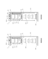
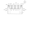
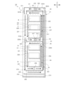
- FIG. 1 is a vertical cross-sectional view of a storage device according to a first embodiment; Block diagram of a refrigeration system according to the first embodiment Explanatory diagram of operation start control in the storage device according to the first embodiment Vertical cross-sectional view of a storage device according to the second embodiment Vertical cross-sectional view of a storage device according to the third embodiment Vertical cross-sectional view of a storage device according to the fourth embodiment Vertical cross-sectional view of a storage device according to the fifth embodiment Vertical cross-sectional view of a storage device according to the sixth embodiment Longitudinal sectional view of a storage device according to the seventh embodiment Front view of the inside of the storage device according to the seventh embodiment Sectional view along line XI-XI in FIG. Vertical cross-sectional view of a storage device according to the eighth embodiment Vertical cross-sectional view of a storage device according to the ninth embodiment
- FIG. 1 is a vertical cross-sectional view of a storage device.
- the front side is the side facing the user or the conveying device of the article when the article is taken in and out of the freezer or refrigerated storage of the storage device, and the rear side is the opposite side of the front side.
- the right side is the right side as viewed from the user or the transport device, and the left side is the opposite side of the right side.
- the upper side is the upper side in the posture when the user or the conveying device takes in and out the article, and the lower side is the opposite side of the upper side.
- “width" means length in the left-right direction unless otherwise specified.
- the storage device 1 shown in FIG. 1 stores the article Z at a refrigerated temperature (eg, +1° C. or higher and +5° C. or lower) or a frozen temperature (eg, about -20° C.).
- Articles Z are, for example, daily necessities, fresh food and frozen food.
- the storage of the articles Z in the storage device 1 may be performed manually by the user, or may be performed by a transport device.
- the storage device 1 includes a body portion 2 and an air curtain generating portion 3 .
- the body part 2 has a housing 21 .
- the housing 21 is formed in the shape of a rectangular parallelepiped box with an open front surface by a top wall 211, a bottom wall 212, a rear wall 213, and left and right side walls 214, each of which has heat insulating properties.
- a virtual freezer 22 and a refrigerated storage 23 are arranged in the internal space of the housing 21 .
- portions corresponding to the freezer storage 22 and the cold storage 23 are indicated by two-dot chain lines.
- the freezer storage 22 and the cold storage 23 may actually be arranged as hardware.
- the freezer 22 stores the article Z at a freezing temperature.
- Freezer storage 22 is positioned above the internal space of housing 21 .
- the freezer 22 includes, for example, three shelves 221 arranged vertically and an upper back plate 222 .
- Each shelf 221 is arranged to bridge the left and right side walls 214 . Each shelf 221 is configured so that an article Z can be placed thereon. Articles Z placed on each shelf 221 may be stored in storage boxes. An upper opening 22A, which is an opening on the front side of the freezer storage 22, is not closed. Articles Z are taken in and out of the freezer storage 22 through the upper opening 22A.
- the upper back plate 222 separates the internal space of the freezer storage 22 from a portion located behind the freezer storage 22 in the second flow path 311 described later.
- the upper back plate 222 is provided so as to close the rear opening surrounded by the upper wall 211, the left and right side walls 214, and the bottom shelf 221, except for the upper end portion. . In other words, a gap is formed between the upper end of the upper back plate 222 and the upper wall 211 .
- the refrigerated storage 23 stores the article Z at a refrigerated temperature.
- Refrigerating storage 23 is positioned below the internal space of housing 21 , that is, below freezing storage 22 .
- the cold storage 23 has, for example, four shelves 231 arranged vertically. Each shelf 231 is arranged to span the left and right side walls 214 . Each shelf 231 is configured so that an article Z can be placed thereon.
- a lower opening 23A which is an opening on the front side of the refrigerator storage 23, is not closed. Articles Z are taken in and out of the cold storage 23 through the lower opening 23A.
- An intermediate plate member 223 , a rear plate member 224 and a lower plate member 232 are further provided inside the housing 21 .
- the intermediate plate member 223 divides the internal space of the housing 21 into upper and lower parts.
- the intermediate plate member 223 is arranged so as to bridge the left and right side walls 214 at a position a predetermined distance downward from the bottom shelf 221 .
- the intermediate plate-like member 223 is arranged such that its front end is positioned forward of the front end of the shelf 221 and its rear end is positioned approximately midway between the upper back plate 222 and the rear wall 213 .
- the front end of the intermediate plate member 223 is formed with an extension 223A extending upward.
- the extending portion 223 ⁇ /b>A has a plate-like shape whose front surface is substantially parallel to the vertical direction and whose width is the same as the width of the intermediate plate-like member 223 .
- the upper end of the extending portion 223A is located below the bottom shelf 221. As shown in FIG. The upper end of the extending portion 223A is positioned substantially directly below the rear end of the duct projecting portion 321B, which will be
- a rear plate member 224 is provided at the rear end of the intermediate plate member 223 and extends upward from the rear end.
- the rear plate member 224 is arranged so as to span the left and right side walls 214 .
- the rear plate-shaped member 224 partitions the space in front of the rear plate-shaped member 224 and the space behind it so that the air cannot freely come and go.
- the lower plate member 232 is arranged so as to bridge the left and right side walls 214 at a position a predetermined distance downward from the lowest shelf 231 .
- the lower plate-like member 232 partitions the upper space and the lower space of the lower plate-like member 232 so that the air cannot freely come and go.
- the lower plate-like member 232 has a front end positioned substantially directly below the front end of the duct projecting portion 321B and a rear end fixed to the rear wall 213 .
- the air curtain generator 3 generates a first air curtain C1 and a second air curtain C2.
- the first air curtain C1 cools the inside of the cold storage 23 by covering the lower opening 23A, thereby bringing the temperature of the cold storage 23 to the refrigerating temperature.
- the second air curtain C2 cools the inside of the freezer storage 22 by covering the upper opening 22A, and sets the temperature of the freezer storage 22 to the freezing temperature.
- the air curtain generator 3 includes a second air curtain generator 31 and a first air curtain generator 32 .
- the second air curtain generating section 31 includes a second flow path 311, a second heat exchanger 417 that constitutes a refrigerating device 4 (see FIG. 2), which will be described later, and a second fan 312.
- the second flow path 311 passes the second air A2 used for generating the second air curtain C2 and the air constituting the second air curtain C2 to the rear side of the freezer storage 22, the upper side, the front side of the upper opening 22A, and the air that constitutes the second air curtain C2. It is circulated in the space between the freezer storage 22 and the cold storage 23.
- the second flow path 311 includes a bottom shelf 221 , an intermediate plate-like member 223 , an upper back plate 222 , a rear plate-like member 224 , an upper wall 211 , a duct projecting portion 321 B, and left and right side walls 214 . It is composed of
- the second fan 312 is arranged in front of the second heat exchanger 417 above the intermediate plate member 223 .
- the second fan 312 sends the second air A2 obtained by heat exchange in the second heat exchanger 417 backward.
- the second air A2 sent rearward by the second fan 312 is guided by the rear plate-shaped member 224 and the upper wall 211 to flow through the rear and upper sides of the freezer storage 22, and then reaches the rear end of the duct projecting portion 321B. It flows vertically downward by guidance.
- the second air A2 flowing vertically downward generates a second air curtain C2 that covers the entire upper opening 22A and extends vertically downward. After passing through the front side of the upper opening 22A, part of the air forming the second air curtain C2 flows rearward under the guidance of the extending portion 223A and the intermediate plate-shaped member 223, and undergoes heat exchange in the second heat exchanger 417.
- the air that forms the second air A2 and the second air curtain C2 is guided by the second flow path 311 to the rear side of the freezer storage 22, the upper side, the front side of the upper opening 22A, and the freezer storage. 22 and refrigerated storage 23.
- the first air curtain generating section 32 includes a first flow path 321 , a first heat exchanger 415 that constitutes the refrigerating device 4 , and a first fan 322 .
- the first flow path 321 directs the first air A1 used for generating the first air curtain C1 and the air constituting the first air curtain C1 to the front side of the upper opening 22A and the lower opening 23A and the bottom of the refrigerator storage 23. circulating between the side, the rear of the cold storage 23 and the freezer 22 and the top of the freezer 22 .
- the first flow path 321 is composed of an upper duct 321A, a lower plate-like member 232, a lowest shelf 231, a rear wall 213, a rear plate-like member 224, and left and right side walls 214. As shown in FIG.
- the front portions of the upper opening 22A and the lower opening 23A in the first flow path 321 are the rear end of the duct projecting portion 321B and the extending portion of the intermediate plate member 223 in the internal space of the housing 21. 223A, front of the shelf 231, and rear of the virtual plane connecting the front end of the duct projecting portion 321B and the front end of the lower plate member 232. .
- a portion of the first flow path 321 below the refrigerator storage 23 is defined by the space between the lower plate member 232 and the bottom shelf 231 in the internal space of the housing 21 .
- a portion of the first flow path 321 on the rear side of the refrigerator storage 23 is formed by a space behind the shelf 231 and in front of the rear wall 213 in the internal space of the housing 21 .
- a portion of the first flow path 321 on the rear side of the freezer storage 22 is formed by a space behind the rear plate-shaped member 224 and in front of the rear wall 213 in the internal space of the housing 21 .
- there is A portion of the first flow path 321 above the freezer storage 22 is defined by the internal space of the upper duct 321A.
- the upper duct 321A is arranged on the upper wall 211.
- the front end side of the upper duct 321A is bent downward.
- a portion extending downward on the front end side of the upper duct 321A constitutes a duct protruding portion 321B that is inserted through an opening formed in the upper wall 211 and protrudes downward from the upper wall 211 .
- the width of the opening of the duct projecting portion 321B is equal to or greater than the width of the upper opening 22A of the freezer 22 and equal to or greater than the width of the lower opening 23A of the cold storage 23 .
- the opening at the rear end of the upper duct 321A is connected to the opening at the upper end of the tubular portion formed by the rear wall 213, the rear plate member 224, and the left and right side walls 214. As shown in FIG.
- the first fan 322 is arranged behind the first heat exchanger 415 in the upper duct 321A.
- the first fan 322 forwards the first air A1 obtained by heat exchange in the first heat exchanger 415 .
- the first air A1 sent forward by the first fan 322 flows vertically downward under the guidance of the duct projecting portion 321B.
- the first air A1 that flows vertically downward generates a first air curtain C1 that covers the entire upper opening 22A and the lower opening 23A and extends vertically downward.
- part of the air forming the first air curtain C1 flows rearward and upward in order guided by the lower plate member 232 and the rear wall 213, and reaches the rear end of the upper duct 321A. side and is used for heat exchange in the first heat exchanger 415 .
- the air that forms the first air A1 and the first air curtain C1 is guided by the first flow path 321 to the front side of the upper opening 22A and the lower opening 23A, the lower side of the refrigerator storage 23, and the refrigerator. It circulates between storage 23 and the back of freezer 22 and the top of freezer 22 .
- the first air curtain C1 and the second air curtain C2 have the function of separating the inside of the housing 21 from the outside of the housing 21 on the front side.
- Fig. 2 is a block diagram of the refrigeration system.
- the storage device 1 further includes a refrigeration device 4 .
- the freezer 4 cools the freezer storage 22 and the cold storage 23 .
- the refrigerating device 4 includes various devices constituting a refrigerating circuit 41 , a refrigerating temperature sensor 43 , a refrigerating temperature sensor 44 , a high pressure sensor 45 , and a controller 46 .
- the refrigerating circuit 41 exchanges heat with the refrigerant to provide the first air A1 for setting the temperature of the refrigerating storage 23 to the refrigerating temperature, and the second air A1 for setting the temperature of the refrigerating storage 22 to the freezing temperature. Generate air A2.
- the refrigerating circuit 41 includes a compressor 411, a heat radiation heat exchanger 412, a heat radiation heat exchanger fan 413, a first throttle portion 414, the above-described first heat exchanger 415, a second throttle portion 416, the above-described and a second heat exchanger 417.
- the compressor 411 is, for example, a rotary compressor. One end of a pipe 421 is connected to the compressor 411 . Compressor 411 compresses the refrigerant and sends it to pipe 421 .
- the other end of the pipe 421 and one end of the pipe 422 are connected to the radiation heat exchanger 412 .
- the radiation heat exchanger 412 cools the refrigerant compressed by the compressor 411 and sends it to the pipe 422 .
- the radiation heat exchanger fan 413 increases the cooling efficiency of the radiation heat exchanger 412 by sending air to the radiation heat exchanger 412 .
- the first throttle portion 414 is, for example, an electric expansion valve.
- the other end of the pipe 422 and one end of the pipe 423 are connected to the first narrowed portion 414 .
- the first throttle section 414 throttles the refrigerant cooled by the heat radiation heat exchanger 412 and sends the refrigerant to the pipe 423 .
- the other end of the pipe 423 and one end of the pipe 424 are connected to the first heat exchanger 415 .
- the first heat exchanger 415 exchanges heat between the refrigerant throttled by the first throttle portion 414 and air, and sends the heat-exchanged refrigerant to the pipe 424 .
- the second throttle portion 416 is, for example, an electric expansion valve.
- the other end of the pipe 424 and one end of the pipe 425 are connected to the second narrowed portion 416 .
- the second throttle section 416 throttles the refrigerant heat-exchanged in the first heat exchanger 415 and sends it to the pipe 425 .
- the second heat exchanger 417 is connected to the other end of the pipe 425 and one end of the pipe 426 .
- the second heat exchanger 417 exchanges heat between the refrigerant throttled by the second throttle portion 416 and air, and sends the heat-exchanged refrigerant to the pipe 426 .
- the other end of pipe 426 is connected to compressor 411 , and the refrigerant sent from second heat exchanger 417 is returned to compressor 411 .
- the freezer temperature sensor 43 detects the temperature of the freezer storage 22 .
- a refrigerator temperature sensor 44 detects the temperature of the refrigerator storage 23 .
- the high-pressure sensor 45 detects the pressure (high-pressure) of a portion (for example, pipes 421 and 422) from the compressor 411 to the first throttle portion 414 in the refrigerant passage.
- the control unit 46 controls various devices constituting the refrigeration circuit 41 and the air curtain generation unit based on the temperature detection results of the freezing temperature sensor 43 and the refrigerator temperature sensor 44 or the pressure detection results of the high pressure sensor 45. 3 to adjust the temperatures of the freezer 22 and the refrigerator 23 to appropriate temperatures.
- FIG. 3 is an explanatory diagram of operation start control in the storage device.
- the control unit 46 of the refrigeration device 4 controls each device constituting the refrigeration circuit 41 to generate an air curtain as shown in the left diagram of FIG. While the second air curtain C2 is generated by the unit 3, the first air curtain C1 is not generated.
- the first air A1 and the second air A2 are generated by the first heat exchanger 415 and the second heat exchanger 417, respectively, the second fan 312 is driven, and the second air A2 is generated. is sent to the rear of the freezer 22 while the first air A1 is not sent to the front of the refrigerator 23 without driving the first fan 322 .
- control unit 46 continues the control of not generating the first air curtain C1 while generating the second air curtain C2. Then, the control unit 46 switches the control of the air curtain generation unit 3 when the above one condition is satisfied. Specifically, the control unit 46 starts generating the first air curtain C1 while continuing the generation of the second air curtain C2 by the air curtain generating unit 3 .
- control can be exemplified by control to start driving the first fan 322 and send the first air A ⁇ b>1 to the front of the refrigerator storage 23 .
- the first condition is that the temperature inside the freezer storage 22 falls to the target temperature.
- the control unit 46 determines whether or not the first condition is satisfied. In this way, by switching the control of the air curtain generator 3 based on the temperature inside the freezer storage 22, the inside of the freezer storage 22 can be rapidly cooled.
- the second condition is that the high pressure is higher than the preset control switching pressure. Based on the detection result of the high-pressure sensor 45, the control unit 46 determines whether or not the second condition is satisfied.
- the reason for switching the control of the air curtain generator 3 based on the high pressure is as follows. As the second heat exchanger 417 cools down, it is necessary to throttle the second throttle portion 416 in order to remove the degree of superheat of the refrigerant. However, if the second throttle portion 416 is throttled, the high pressure may become too high due to the refrigerant that has nowhere to go. Therefore, when the high pressure becomes higher than the control switching pressure, the driving of the first fan 322 is started to promote the heat exchange by the first heat exchanger 415, that is, the generation of the first air curtain C1. By starting , it is possible to suppress the high pressure from becoming too high.
- a portion of the air that has passed in front of freezer storage 22 is guided rearward under freezer storage 22 by intermediate plate member 223 and reused for heat exchange in second heat exchanger 417 .
- the extending portion 223A separates the first air curtain C1 and the second air curtain C2 that flow down in parallel again into two, and the relatively low-temperature air on the rear side reaches the refrigeration temperature on the front side. prevent it from flowing into
- the air of the first air curtain C1 that has undergone heat exchange with the air of the second air curtain C2 covers the entire lower opening 23A.
- the air in the first air curtain C1 that has passed in front of the refrigerator storage 23 flows backward and upward through the lower plate member 232 and the rear wall 213 in this order, and then flows upward. It is guided to duct 321 A and reused for heat exchange in first heat exchanger 415 . Due to the circulation of the air of the first air A1 and the first air curtain C1, part of the air of the second air curtain C2 lowers the temperature lower than the refrigeration temperature before the control of the air curtain generator 3 is switched. The temperature inside the cooled refrigerating storage 23 gradually rises.
- the temperature in the freezer storage 22 is adjusted to the freezing temperature (eg, ⁇ 20° C.), and the temperature in the cold storage 23 is adjusted to the refrigerating temperature (eg, +3° C.). .
- the second air curtain C2 is generated to cool the freezer storage 22, so that both the first air curtain C1 and the second air curtain C2 are generated to cool the freezer storage 22.
- the temperature of the air flowing in front of the upper opening 22A can be lowered as compared with the case of cooling the . Therefore, the temperature of the freezer storage 22 can be lowered quickly.
- the air in the lower portion of the second air curtain C2 (hereinafter sometimes referred to as “lower air”) is compared with the air in the upper portion (hereinafter sometimes referred to as “upper air”). Therefore, the time during which heat is exchanged with the air in the first air curtain C1 is longer. Therefore, the temperature of the lower air is higher than that of the upper air. For this reason, the space (for example, the storage space above the top shelf 221) facing the upper air is more strongly affected by the temperature of the upper air than the space facing the lower air. The temperature of the space (for example, the storage space between the bottom shelf 221 and the second shelf 221 from the bottom) that is strongly affected by the temperature of the lower air may rise.
- the cold second air A2 that has just been heat-exchanged and that has not undergone heat exchange with the air in the first air curtain C1 is placed after the freezer storage 22. On the side, it flows from bottom to top.
- the heat exchange between the second air A2 and the air inside the freezer storage 22 through the upper back plate 222 allows the freezer storage 22 to be cooled.
- the second air A2 located on the lower side takes a shorter time to perform heat exchange via the upper back plate 222 than the second air A2 located on the upper side. Therefore, the temperature of the second air A2 positioned on the lower side is lower than the temperature of the second air A2 positioned on the upper side.
- the lower part of the freezer storage 22 can be cooled more strongly than the upper part with the second air A2.
- the temperature of the lower part of the freezer storage 22 is increased. It is possible to suppress the temperature from becoming higher than the temperature of the upper part, that is, the occurrence of unevenness in the distribution of the internal temperature of the freezer 22, and to appropriately adjust the temperature inside the freezer 22 and the refrigerator 23. It is possible to provide the storage device 1 that can be used.
- FIG. 4 is a vertical cross-sectional view of the storage device.
- the control unit 46 drives the second fan 312 to send the second air A2 to the rear of the freezer storage 22.
- the second air A2 sent rearward at the lower side of the freezer storage 22 first flows upward from the bottom at the rear side of the freezer storage 22 .
- all the second air A2 flows through the upper side of the freezer storage 22 and in front of the upper opening 22A.
- the part enters the freezer storage 22 through the upper through hole 222A and flows forward.
- the air constituting the second air curtain C2 is Air whose temperature is higher than that of the second air A2 through heat exchange with the air of the first air curtain C1 can be suppressed from entering the inside of the freezer storage 22 from the front side. Therefore, a decrease in cooling efficiency of the freezer storage 22 can be suppressed.
- the air of the first air curtain C1 flowing vertically downward is also drawn toward the freezer storage 22, that is, toward the second air curtain C2.
- the amount of heat transferred between the air of the first air curtain C1 and the air of the second air curtain C2 increases, compared to the case where the air of the first air curtain C1 flows vertically downward, The amount of mixture of is increased. Therefore, the temperature of the air in the first air curtain C1 may drop too much when it reaches the front of the lower opening 23A, and the temperature of the refrigerator storage 23 may become lower than the target temperature.
- the air forming the second air curtain C2 is suppressed from entering the inside of the freezer storage 22 from the front side. It is possible to prevent the air from the air curtain C1 from being drawn toward the second air curtain C2. Therefore, it is possible to suppress an increase in the amount of heat transferred between the air in the first air curtain C1 and the air in the second air curtain C2, and an increase in the amount of mixture of both airs. It is possible to suppress the temperature of the air from dropping too much. As a result, the temperature of the air in the first air curtain C1 can be appropriately adjusted, and the temperature of the refrigerator storage 23 can be prevented from becoming lower than the target temperature.
- FIG. 5 is a longitudinal sectional view of the storage device.
- a storage device 1B shown in FIG. 5 differs from the storage device 1A of the second embodiment in that a lower back plate 233 is arranged.
- the lower back plate 233 configures the cold storage 23 and separates the internal space of the cold storage 23 from a portion of the first flow path 321 located on the rear side of the cold storage 23 .
- the lower back plate 233 is provided so as to close the rear opening surrounded by the intermediate plate member 223 , the left and right side walls 214 and the bottom shelf 231 .
- the lower back plate 233 constitutes the first flow path 321 together with the upper duct 321A, the lower plate member 232, the rear wall 213, the rear plate member 224, and the left and right side walls 214.
- the portion of the first flow path 321 on the rear side of the refrigerator 23 is the space behind the lower back plate 233 and in front of the rear wall 213 in the internal space of the housing 21 . It is composed of Other parts of the first flow path 321 are configured similarly to the first flow path 321 of the second embodiment.
- a lower through-hole 233 ⁇ /b>A that penetrates the lower back plate 233 is formed at a portion of the lower back plate 233 above each shelf 231 by a predetermined distance.
- the configuration exemplified as the upper through-hole 222A can be applied to the lower through-hole 233A.
- the lower through-hole 233A guides the air forming the first air curtain C1 inside the refrigerator storage 23 to the first flow path 321. As shown in FIG.
- the control unit 46 drives the second fan 312 and the first fan 322 to generate the second air curtain C2 and the first air curtain C1.
- a part of the air of the first air curtain C1 covering the lower opening 23A does not flow downward, but passes through the inside of the refrigerator storage 23 and the lower through-hole 233A and enters the first channel 321. It is guided to upper duct 321 A and reused for heat exchange in first heat exchanger 415 .
- the air of the first air curtain C1 flowing vertically downward is The air is prevented from being drawn into the second air curtain C2, and the temperature of the air in the first air curtain C1 is properly adjusted.
- the lower back plate 233 is installed and the plurality of lower through holes 233A are formed in the lower back plate 233 so as to be evenly distributed, the first air curtain C1 of air uniformly flows into the refrigerator storage 23 through the lower opening 23A. Therefore, it is possible to suppress the occurrence of temperature unevenness in the refrigerator storage 23 .
- FIG. 6 is a longitudinal sectional view of the storage device.
- the storage device 1C shown in FIG. 6 has a square box-shaped storage body B for storing the article Z placed on each shelf 221, 231 of the freezer 22 and the cold storage 23, and the second heat storage device 1C. It is different from the storage device 1 of the first embodiment in that the positions of the exchanger 417 and the second fan 312 are switched, and the configuration of the upper duct 321C.
- the storage body B is formed in the shape of a square box whose upper surface is not closed, and is configured so that the article Z can be taken in and out from above. Note that the storage body B does not have to be in the shape of a square box as long as it can store the article Z, and the opening for taking in and out the article Z may be provided with a lid.
- a duct protruding portion 321B of the upper duct 321C is formed in a square tubular shape.
- the rear end of the duct projecting portion 321B functions as a second upper front guide portion 313 that guides the second air A2 flowing forward in the second flow path 311 above the freezer storage 22 to the front side of the upper opening 22A. do.
- the second upper front guide portion 313 is provided with a plate-like inclined portion 313A that is inclined such that the lower end is located on the rear side of the upper end.
- the inclined portion 313A is formed so that the front surface of the container B placed on the topmost shelf 221 of the freezer storage 22 is positioned on an imaginary line K extending from the lower end in the inclined direction of the inclined portion 313A. ing.
- the control unit 46 drives the second fan 312 to send the second air A2 to the rear of the freezer storage 22.
- the second air A2 sent rearward from the lower side of the freezer storage 22 flows in front of the upper opening 22A through the rear side and the upper side of the freezer storage 22, thereby covering the entire upper opening 22A.
- a curtain C2 is generated.
- the second air A2 is guided obliquely rearward by the inclined portion 313A rather than directly downward.
- the second air A2 guided obliquely rearward is guided directly below by the front surface of the container B.
- a second air curtain C2 covering the entire upper opening 22A is generated by the second air A2 guided directly below.
- the second air curtain C2 generated by the second air A2 moves downward in the front-rear direction.
- the air forming the second air curtain C2 for example, the air at ⁇ 20° C.
- the air forming the first air curtain for example, +15° C.
- the second air A2 that has passed through the upper duct 321C is guided not directly downward but obliquely rearward by the inclined portion 313A, and then guided directly downward by the front surface of the storage body B.
- the second air curtain C2 since the flow path of the second air A2 formed by the inclined portion 313A becomes narrower toward the lower side, the flow velocity of the second air A2 passing through the inclined portion 313A can be increased, and the second air curtain It is possible to suppress the expansion of C2 in the front-rear direction. Therefore, it is possible to prevent the air forming the second air curtain C2 and the air forming the first air curtain from flowing to the front side of the lower opening 23A, thereby preventing the temperature of the refrigerator storage 23 from dropping too much. be able to.
- FIG. 7 is a longitudinal sectional view of the storage device.
- a storage device 1D shown in FIG. It differs from the storage device 1 of the first embodiment in that the positions of the exchanger 417 and the second fan 312 are interchanged, and the configuration of the intermediate plate member 225 .
- the configuration of the lower part of the storage device 1D is the same as that of the storage device 1 of the first embodiment, the illustration thereof is omitted.
- An extension 225A extending upward is formed at the front end of the intermediate plate member 225 .
- the extending portion 225 ⁇ /b>A has a plate-like shape whose front surface is substantially parallel to the vertical direction and whose width is the same as the width of the intermediate plate-like member 225 .
- the upper end of the extension 225A is located below the bottom shelf 221. As shown in FIG.
- the lowest shelf 221 functions as a lower member 221A forming the lower end of the freezer storage 22 .
- the upper end of the extending portion 225A is positioned substantially directly below the rear end of the duct projecting portion 321B.
- the length L from the front end of the lower member 221A to the upper end of the extension 225A when the storage device 1D is viewed from above is equal to or greater than the height H of the second heat exchanger 417.
- the second heat exchanger 417 is arranged so that its front end is positioned forward of the front end of the lower member 221A.
- the front end of the second heat exchanger 417 may be positioned at the same position as the front end of the lower member 221A or on the rear side of the front end of the lower member 221A.
- the second heat exchanger 417 is arranged so that there is no or almost no gap between it and the lower member 221A and between it and the intermediate plate member 225 .
- the control unit 46 By driving the second fan 312, the control unit 46 generates the second air curtain C2 that covers the entire upper opening 22A.
- the air of the second air curtain C2 that has passed in front of the freezer storage 22 is guided to the second heat exchanger 417 by the intermediate plate member 225 while being restricted from flowing forward by the extending portion 225A.
- the length L of the air inlet is shorter than the height H of the second heat exchanger 417, pressure loss may occur at the air inlet, and the amount of air flowing through the second heat exchanger 417 may decrease. be.
- the air that has not flowed to the second heat exchanger 417 may flow to the front side of the lower opening 23A together with the air forming the first air curtain, and the temperature of the refrigerator storage 23 may drop too much. .
- FIG. 8 is a vertical cross-sectional view of the storage device.
- a storage device 1E shown in FIG. 8 differs from the storage device 1D of the fifth embodiment in the configuration of an intermediate plate member 226.
- FIG. 8 since the configuration of the lower part of the storage device 1E is the same as that of the storage device 1D of the fifth embodiment, the illustration thereof is omitted.
- the extending portion 226A located at the front end of the intermediate plate-shaped member 226 is formed so that its height G is at least half the height H of the second heat exchanger 417 (0.5 ⁇ H).
- the control unit 46 By driving the second fan 312, the control unit 46 generates the second air curtain C2 that covers the entire upper opening 22A.
- the air of the second air curtain C2 that has passed in front of the freezer storage 22 is guided to the second heat exchanger 417 by the intermediate plate member 226 while being restricted from flowing forward by the extending portion 226A.
- the height G of the extension 226A is less than half the height H of the second heat exchanger 417, the position at which the extension 226A regulates the forward air flow is lowered. Due to the spread of the air by the curtain C2, the amount of air flowing through the second heat exchanger 417 may decrease. In this case, the air that has not flowed to the second heat exchanger 417 may flow to the front side of the lower opening 23A together with the air forming the first air curtain, and the temperature of the refrigerator storage 23 may drop too much. .
- the height G of the extension 226A is half or more of the height H of the second heat exchanger 417, so that the extension 226A restricts the air flow to the front side.
- the position can be increased, and reduction in the amount of air flowing through the second heat exchanger 417 can be suppressed. Therefore, it is possible to prevent the air in the second air curtain C2 from flowing to the front side of the lower opening 23A together with the air forming the first air curtain, thereby preventing the temperature of the refrigerator storage 23 from dropping too much. can.
- FIG. 9 is a vertical cross-sectional view of the storage device.
- FIG. 10 is a front view of the interior of the storage device.
- 11 is a cross-sectional view taken along line XI-XI of FIG. 9.
- FIG. 9 is a vertical cross-sectional view of the storage device.
- FIG. 10 is a front view of the interior of the storage device.
- 11 is a cross-sectional view taken along line XI-XI of FIG. 9.
- the storage device 1 of the first embodiment differs from the storage device 1 of the first embodiment in that the positions of the second heat exchanger 417 and the second fan 312 are switched, and the configuration of the first channel 323 and the second channel 314 .
- the first flow path 323 is different from the first flow path 323 of the first embodiment in the configuration of the part on the front side of the upper opening 22A, and the other parts are the same as the first flow path 323 of the first embodiment. is.
- a pair of partitions 324 are arranged. Each partition 324 is formed to extend from the lower end of the duct projecting portion 321B to the lower end of the intermediate plate member 223. As shown in FIG.
- Each partition 324 is formed in an L-shaped plate shape by a first plate-shaped portion 324A and a second plate-shaped portion 324B.
- Each first plate-like portion 324A is formed to extend left and right from both left and right ends of the rear end of the duct projecting portion 321B to the side wall 214 of the housing 21 .
- Each second plate-shaped portion 324B is formed to extend forward from the end of each first plate-shaped portion 324A on the side of the duct protrusion 321B to the front end of the duct protrusion 321B.
- the right heat exchange impermissible guide portion 323B is formed by the area between the right partition 324 and the right side wall 214 .
- the left heat exchange impermissible guide portion 323B is formed by the area between the left partition 324 and the left side wall 214 .
- each of the non-permitting heat exchange guide portions 323B forms a first air curtain C12 (hereinafter sometimes referred to as an "outer first air curtain C12"). ) is generated.
- Each heat exchange impermissible guide portion 323B has a lower opening so as not to exchange heat between the air forming the outer first air curtain C12 and the air forming the second air curtain C2 on the front side of the upper opening 22A. Guide to the front side of 23A.
- the second flow path 314 is different from the first flow path 323 of the first embodiment in the upper part of the freezer storage 22, and the other parts are the same as the second flow path 311 of the first embodiment.
- An upper front duct forming member 316 that forms a rectangular cylindrical upper front duct 315 together with the rear end of the duct protrusion 321B is arranged on the rear side of the duct protrusion 321B.
- the width of the upper front duct 315 is the same as the width of the heat exchange permitting guide portion 323A.
- the depth (the length in the front-rear direction) of the upper front duct 315 may be substantially the same as the depth of the heat exchange permitting guide portion 323A.
- the control unit 46 By driving the second fan 312, the control unit 46 generates the second air curtain C2 that covers the entire upper opening 22A. Further, the control unit 46 sends the first air A1 forward by driving the first fan 322 .
- a central first air curtain C11 passing through the heat exchange permitting guide portion 323A is generated by a portion of the first air A1 passing through the duct projecting portion 321B.
- the remaining first air A1 passing through the duct projecting portion 321B forms an outer first air curtain C12 passing through the heat exchange impermissible guide portion 323B.
- the air in the outer first air curtain C12 does not exchange heat with the air in the second air curtain C2 due to the presence of the partition 324, and the air in the lower opening 23A Guided to the front.
- the partition 324 disappears. exchange takes place.
- the temperature of the outer first air curtain C12 is approximately the same as the temperature of the first air A1, but the temperature of the central first air curtain C11 is the same as the temperature of the first air curtain C11 due to heat exchange with the air of the second air curtain C2. It is lower than the temperature of air A1. Therefore, the cold storage 23 is adjusted to a temperature higher than the temperature of the central first air curtain C11 and lower than the temperature of the first air A1. Therefore, the temperature of the air in the central first air curtain C11, which has undergone heat exchange with the air in the second air curtain C2, is lower than the refrigeration temperature due to, for example, the temperature in the freezer storage 22 becoming lower. Even if the temperature becomes low, the temperature of the air in the central first air curtain C11 can be increased by heat exchange with the air in the outer first air curtain C12, thereby preventing the temperature of the refrigerator storage 23 from dropping too much. can do.
- the partition 324 may be affixed with a heat insulating material. Moreover, the partition 324 may be formed so that its lower end is positioned below the lower end of the intermediate plate member 223 . Also, the partition 324 may have a shape other than the L-shaped plate shape, for example, it may have a cylindrical shape. Also, the temperature of the first air A1 may be changed by controlling the rotational speed of the first fan 322 according to the temperature of the refrigerator 23 .
- FIG. 12 is a vertical cross-sectional view of the storage device.
- the storage device 1G shown in FIG. 12 has a rectangular box-shaped storage body B for storing the article Z placed on each shelf 221, 231 of the freezer 22 and the cold storage 23, and the second heat storage device 1G. It differs from the storage device 1 of the first embodiment in that the positions of the exchanger 417 and the second fan 312 are interchanged, and that the third fan 33 and the lower back plate 234 are arranged.
- the third fan 33 constitutes the air curtain generator 3.
- the third fan 33 is arranged on the lower plate-like member 232 so as to be positioned below the cold storage 23, and sends the air of the first air curtain C1 and the circulating air A3, which will be described later, backward.
- the lower back plate 234 constitutes the cold storage 23 and separates the internal space of the cold storage 23 from the portion of the first flow path 321 located on the rear side of the cold storage 23 .
- the lower back plate 234 covers a portion of the rear opening surrounded by the intermediate plate member 223, the left and right side walls 214, and the bottom shelf 231 above the uppermost container B. It is provided so as to block the part to be removed.
- a region between the upper end of the lower back plate 234 and the lower surface of the intermediate plate member 223 functions as a circulation through hole 234A. Circulation through-hole 234A guides part of the air flowing behind lower back plate 234 as circulating air A3 to lower opening 23A through an upper portion in refrigerator storage 23 .
- the control unit 46 generates the first and second air curtains C1 and C2 by driving the first and second fans 322 and 312 while the third fan 33 is being driven.
- the air of the first air curtain C1 that has undergone heat exchange with the air of the second air curtain C2 flows rearward along the lower plate member 232 after passing in front of the lower opening 23A.
- the flow velocity of the air flowing along the lower plate member 232 is increased by the third fan 33 .
- the air that has passed through the third fan 33 flows upward along the rear wall 213, and part of it passes behind the freezer storage 22 and flows into the upper duct 321A, while the rest flows through the circulation through-hole 234A. through the refrigerating storage chamber 23 .
- the air that has flowed through the upper duct 321A is reused for heat exchange in the first heat exchanger 415.
- the air that has flowed upward in the refrigerator storage 23 flows forward as circulating air A3, and when it reaches the lower opening 23A, it flows downward together with the air in the first air curtain C1.
- the air reaching the lower plate-shaped member 232 passes through the third fan 33 and is partly reused for heat exchange in the first heat exchanger 415, while the rest is refrigerated as circulating air A3. It flows above the stocker 23 .
- part of the air flowing behind the refrigerating storage 23 is distributed between the upper portion in the refrigerating storage 23, the front side of the lower opening 23A, and the lower and rear portions of the refrigerating storage 23.
- FIG. 13 is a vertical cross-sectional view of the storage device.
- a storage device 1H shown in FIG. 13 differs from the storage device 1G of the eighth embodiment in that a bottom member 235 and a refrigerating fan 236 are arranged, and in the shape of a rear plate member 227.
- the bottom member 235 constitutes the refrigerating storage 23 and is arranged between the bottom shelf 231 and the lower plate member 232 so as to bridge the left and right side walls 214 . That is, the bottom member 235 partitions the space above the bottom member 235 and the space below the bottom member 235 so that air cannot flow freely.
- the bottom member 235 is formed such that its front end is located substantially directly below the front end of the intermediate plate member 223 and behind the front end of the lower plate member 232 .
- the bottom member 235 is formed such that its rear end is located directly below the rear end of the intermediate plate member 223 .
- the refrigerating fan 236 constitutes the refrigerating storage 23, is arranged on the bottom member 235 so as to be located on the lower side in the refrigerating storage 23, and sends circulating air A4 described later backward.
- the rear plate-shaped member 227 is formed in a shape longer downward than the rear plate-shaped member 224 of the eighth embodiment. Specifically, the rear plate-like member 227 is formed so that its center is connected to the rear end of the intermediate plate-like member 223 and its lower end is connected to the rear end of the bottom surface member 235 .
- the bottom shelf 231 , the bottom member 235 , the lower back plate 234 , the rear plate member 227 , the intermediate plate member 223 , and the left and right side walls 214 of the refrigerator 23 are circulated air sent by the refrigerator fan 236 .
- a circulation flow path 34 for circulating the A4 in the rear side, upper side, front side, and lower side in the refrigerator storage 23 is configured.
- the control unit 46 generates the first and second air curtains C1 and C2 by driving the first and second fans 322 and 312 while the refrigerator fan 236 is being driven.
- the air of the first air curtain C1 that has undergone heat exchange with the air of the second air curtain C2 passes in front of the lower opening 23A. while the remainder reaches the lower plate member 232 .
- the air After reaching the lower plate-shaped member 232, the air flows rearward and upward in order by the lower plate-shaped member 232 and the rear wall 213, that is, flows through the lower and rear portions of the first flow path 321, and then flows upward. It is guided to duct 321 A and reused for heat exchange in first heat exchanger 415 .
- the air that has flowed into the refrigerator storage 23 flows backward along the bottom member 235 .
- the flow velocity of the air flowing along the bottom member 235 is increased by the refrigerator fan 236 .
- All the air that has passed through refrigerating fan 236 flows upward along rear plate member 227 as circulating air A4, and then flows upward in refrigerating storage 23 via circulation through-hole 234A.
- the circulating air A4 that has flowed upward in the refrigerator storage 23 reaches the lower opening 23A, it flows downward together with the air in the first air curtain C1 and passes through the refrigerator fan 236 again.
- a circulation flow path 34 for circulating the circulation air A4, and a first flow path 321 for flowing the air reused for heat exchange in the first heat exchanger 415. is partitioned by the rear plate member 227, variation in the amount of the circulating air A4 can be suppressed, and the occurrence of temperature unevenness in the refrigerator storage 23 can be further suppressed.
- a Peltier element or the like may be applied as a configuration for generating the first and second air A1 and A2.
- the air in the first air curtain C1 is configured to be returned around the first heat exchanger 415, it may not be returned, or the air in the second air curtain C2 may be returned around the second heat exchanger 417. Although it is configured to be returned, it may be configured not to be returned.
- the present disclosure can be applied to storage devices.
Landscapes
- Engineering & Computer Science (AREA)
- Mechanical Engineering (AREA)
- Chemical & Material Sciences (AREA)
- Combustion & Propulsion (AREA)
- Physics & Mathematics (AREA)
- Thermal Sciences (AREA)
- General Engineering & Computer Science (AREA)
- Devices That Are Associated With Refrigeration Equipment (AREA)
- Cold Air Circulating Systems And Constructional Details In Refrigerators (AREA)
Priority Applications (2)
| Application Number | Priority Date | Filing Date | Title |
|---|---|---|---|
| JP2023539670A JPWO2023013218A1 (https=) | 2021-08-04 | 2022-05-26 | |
| CN202280054003.6A CN117836577A (zh) | 2021-08-04 | 2022-05-26 | 容纳装置 |
Applications Claiming Priority (2)
| Application Number | Priority Date | Filing Date | Title |
|---|---|---|---|
| JP2021-128182 | 2021-08-04 | ||
| JP2021128182 | 2021-08-04 |
Publications (1)
| Publication Number | Publication Date |
|---|---|
| WO2023013218A1 true WO2023013218A1 (ja) | 2023-02-09 |
Family
ID=85154089
Family Applications (1)
| Application Number | Title | Priority Date | Filing Date |
|---|---|---|---|
| PCT/JP2022/021597 Ceased WO2023013218A1 (ja) | 2021-08-04 | 2022-05-26 | 収納装置 |
Country Status (3)
| Country | Link |
|---|---|
| JP (1) | JPWO2023013218A1 (https=) |
| CN (1) | CN117836577A (https=) |
| WO (1) | WO2023013218A1 (https=) |
Citations (5)
| Publication number | Priority date | Publication date | Assignee | Title |
|---|---|---|---|---|
| JPS58168869A (ja) * | 1982-03-31 | 1983-10-05 | 株式会社サンテム | 冷蔵オ−プンシヨ−ケ−スの冷気循環方法および装置 |
| JPH0979730A (ja) * | 1995-09-14 | 1997-03-28 | Fuji Electric Co Ltd | デュアル型冷凍冷蔵ショーケース |
| JPH1123133A (ja) * | 1997-06-27 | 1999-01-26 | Nakano Refrigerators Co Ltd | 2温度式オープンショーケース |
| JP2000028254A (ja) * | 1998-07-10 | 2000-01-28 | Sanden Corp | オープンショーケース |
| JP2017127421A (ja) * | 2016-01-19 | 2017-07-27 | 富士電機株式会社 | ショーケース |
-
2022
- 2022-05-26 CN CN202280054003.6A patent/CN117836577A/zh active Pending
- 2022-05-26 WO PCT/JP2022/021597 patent/WO2023013218A1/ja not_active Ceased
- 2022-05-26 JP JP2023539670A patent/JPWO2023013218A1/ja active Pending
Patent Citations (5)
| Publication number | Priority date | Publication date | Assignee | Title |
|---|---|---|---|---|
| JPS58168869A (ja) * | 1982-03-31 | 1983-10-05 | 株式会社サンテム | 冷蔵オ−プンシヨ−ケ−スの冷気循環方法および装置 |
| JPH0979730A (ja) * | 1995-09-14 | 1997-03-28 | Fuji Electric Co Ltd | デュアル型冷凍冷蔵ショーケース |
| JPH1123133A (ja) * | 1997-06-27 | 1999-01-26 | Nakano Refrigerators Co Ltd | 2温度式オープンショーケース |
| JP2000028254A (ja) * | 1998-07-10 | 2000-01-28 | Sanden Corp | オープンショーケース |
| JP2017127421A (ja) * | 2016-01-19 | 2017-07-27 | 富士電機株式会社 | ショーケース |
Also Published As
| Publication number | Publication date |
|---|---|
| JPWO2023013218A1 (https=) | 2023-02-09 |
| CN117836577A (zh) | 2024-04-05 |
Similar Documents
| Publication | Publication Date | Title |
|---|---|---|
| CN108317797B (zh) | 冰箱 | |
| US20170059228A1 (en) | Refrigerator and control method thereof | |
| US11692757B2 (en) | Refrigerator | |
| KR102418005B1 (ko) | 냉장고 및 그 제어방법 | |
| KR20120000642A (ko) | 모듈식 냉장고 | |
| KR102320766B1 (ko) | 냉장고 | |
| CN107166849A (zh) | 对开门冰箱 | |
| US11272794B2 (en) | Open-front refrigerator and a method of cooling items therein | |
| WO2023013218A1 (ja) | 収納装置 | |
| JP2015102320A (ja) | 冷蔵庫 | |
| JP2019163917A (ja) | 冷蔵庫 | |
| JP2019086165A (ja) | 冷蔵庫 | |
| KR20180072146A (ko) | 냉장고 | |
| KR101811496B1 (ko) | 냉장고 및 냉장고 제어 방법 | |
| WO2022209699A1 (ja) | 冷凍装置 | |
| JPH11270956A (ja) | 冷蔵庫 | |
| KR20070031721A (ko) | 냉장고 | |
| JP2018080861A (ja) | 冷媒回路装置 | |
| JP2017058940A (ja) | 自動販売機 | |
| JP7233021B2 (ja) | 解凍保冷庫 | |
| JP2023027533A (ja) | 収納装置 | |
| JP2013185775A (ja) | 分配器 | |
| JP2023177921A (ja) | 冷凍装置及び収納装置 | |
| KR100608584B1 (ko) | 사이드 바이 사이드형 냉장고의 냉기순환장치 | |
| JP2017189463A (ja) | ショーケース |
Legal Events
| Date | Code | Title | Description |
|---|---|---|---|
| 121 | Ep: the epo has been informed by wipo that ep was designated in this application |
Ref document number: 22852646 Country of ref document: EP Kind code of ref document: A1 |
|
| WWE | Wipo information: entry into national phase |
Ref document number: 2023539670 Country of ref document: JP |
|
| WWE | Wipo information: entry into national phase |
Ref document number: 202280054003.6 Country of ref document: CN |
|
| NENP | Non-entry into the national phase |
Ref country code: DE |
|
| 122 | Ep: pct application non-entry in european phase |
Ref document number: 22852646 Country of ref document: EP Kind code of ref document: A1 |