WO2023007965A1 - 撮像方法及びプログラム - Google Patents
撮像方法及びプログラム Download PDFInfo
- Publication number
- WO2023007965A1 WO2023007965A1 PCT/JP2022/023585 JP2022023585W WO2023007965A1 WO 2023007965 A1 WO2023007965 A1 WO 2023007965A1 JP 2022023585 W JP2022023585 W JP 2022023585W WO 2023007965 A1 WO2023007965 A1 WO 2023007965A1
- Authority
- WO
- WIPO (PCT)
- Prior art keywords
- wavelength
- subject
- spectral data
- imaging method
- image
- Prior art date
- Legal status (The legal status is an assumption and is not a legal conclusion. Google has not performed a legal analysis and makes no representation as to the accuracy of the status listed.)
- Ceased
Links
Images






Classifications
-
- H—ELECTRICITY
- H04—ELECTRIC COMMUNICATION TECHNIQUE
- H04N—PICTORIAL COMMUNICATION, e.g. TELEVISION
- H04N23/00—Cameras or camera modules comprising electronic image sensors; Control thereof
- H04N23/10—Cameras or camera modules comprising electronic image sensors; Control thereof for generating image signals from different wavelengths
-
- G—PHYSICS
- G01—MEASURING; TESTING
- G01J—MEASUREMENT OF INTENSITY, VELOCITY, SPECTRAL CONTENT, POLARISATION, PHASE OR PULSE CHARACTERISTICS OF INFRARED, VISIBLE OR ULTRAVIOLET LIGHT; COLORIMETRY; RADIATION PYROMETRY
- G01J3/00—Spectrometry; Spectrophotometry; Monochromators; Measuring colours
- G01J3/02—Details
-
- G—PHYSICS
- G01—MEASURING; TESTING
- G01J—MEASUREMENT OF INTENSITY, VELOCITY, SPECTRAL CONTENT, POLARISATION, PHASE OR PULSE CHARACTERISTICS OF INFRARED, VISIBLE OR ULTRAVIOLET LIGHT; COLORIMETRY; RADIATION PYROMETRY
- G01J3/00—Spectrometry; Spectrophotometry; Monochromators; Measuring colours
- G01J3/46—Measurement of colour; Colour measuring devices, e.g. colorimeters
- G01J3/50—Measurement of colour; Colour measuring devices, e.g. colorimeters using electric radiation detectors
- G01J3/51—Measurement of colour; Colour measuring devices, e.g. colorimeters using electric radiation detectors using colour filters
-
- G—PHYSICS
- G01—MEASURING; TESTING
- G01J—MEASUREMENT OF INTENSITY, VELOCITY, SPECTRAL CONTENT, POLARISATION, PHASE OR PULSE CHARACTERISTICS OF INFRARED, VISIBLE OR ULTRAVIOLET LIGHT; COLORIMETRY; RADIATION PYROMETRY
- G01J4/00—Measuring polarisation of light
-
- H—ELECTRICITY
- H04—ELECTRIC COMMUNICATION TECHNIQUE
- H04N—PICTORIAL COMMUNICATION, e.g. TELEVISION
- H04N23/00—Cameras or camera modules comprising electronic image sensors; Control thereof
-
- H—ELECTRICITY
- H04—ELECTRIC COMMUNICATION TECHNIQUE
- H04N—PICTORIAL COMMUNICATION, e.g. TELEVISION
- H04N23/00—Cameras or camera modules comprising electronic image sensors; Control thereof
- H04N23/70—Circuitry for compensating brightness variation in the scene
- H04N23/71—Circuitry for evaluating the brightness variation
-
- H—ELECTRICITY
- H04—ELECTRIC COMMUNICATION TECHNIQUE
- H04N—PICTORIAL COMMUNICATION, e.g. TELEVISION
- H04N23/00—Cameras or camera modules comprising electronic image sensors; Control thereof
- H04N23/70—Circuitry for compensating brightness variation in the scene
- H04N23/72—Combination of two or more compensation controls
-
- H—ELECTRICITY
- H04—ELECTRIC COMMUNICATION TECHNIQUE
- H04N—PICTORIAL COMMUNICATION, e.g. TELEVISION
- H04N23/00—Cameras or camera modules comprising electronic image sensors; Control thereof
- H04N23/70—Circuitry for compensating brightness variation in the scene
- H04N23/74—Circuitry for compensating brightness variation in the scene by influencing the scene brightness using illuminating means
-
- H—ELECTRICITY
- H04—ELECTRIC COMMUNICATION TECHNIQUE
- H04N—PICTORIAL COMMUNICATION, e.g. TELEVISION
- H04N23/00—Cameras or camera modules comprising electronic image sensors; Control thereof
- H04N23/70—Circuitry for compensating brightness variation in the scene
- H04N23/75—Circuitry for compensating brightness variation in the scene by influencing optical camera components
-
- H—ELECTRICITY
- H04—ELECTRIC COMMUNICATION TECHNIQUE
- H04N—PICTORIAL COMMUNICATION, e.g. TELEVISION
- H04N23/00—Cameras or camera modules comprising electronic image sensors; Control thereof
- H04N23/70—Circuitry for compensating brightness variation in the scene
- H04N23/76—Circuitry for compensating brightness variation in the scene by influencing the image signals
Definitions
- the present invention relates to an imaging method and program, and more particularly to an imaging method and program for a multispectral camera.
- Patent Literature 1 describes a technique for estimating the color of a subject using pre-measured spectral sensitivity characteristics of a camera.
- One embodiment according to the technology of the present disclosure provides an imaging method and program capable of obtaining a wavelength image maintaining high wavelength reproducibility.
- An imaging method is an imaging method for imaging a subject with a multispectral camera including a processor, wherein the processor captures first spectral data of a first subject and a second spectrum of a second subject.
- the wavelength selection step of selecting a plurality of wavelengths from the wavelength range of the acquired first to third spectral data, and the wavelength selection step, A plurality of wavelengths are selected based on at least two or more of the factors, with the difference or ratio of the feature amount of two spectral data among the first spectral data, the second spectral data, and the third spectral data as factors, an imaging step of imaging a subject including at least one of a first subject, a second subject, and a third subject at a plurality of wavelengths.
- the wavelength regions of the first to third spectral data are wavelength regions in which at least the wavelength regions of the first spectral data and the wavelength regions of the second spectral data overlap.
- the factors are a first factor that is a difference or ratio of feature amounts between the first spectral data and the third spectral data, and a second factor that is a difference or ratio of feature amounts between the second spectral data and the third spectral data. and selecting a plurality of wavelengths based on a first factor and a second factor.
- one of the plurality of wavelengths is the wavelength at which at least one of the first factor and the second factor is minimized.
- a step of measuring intensity ratios of brightnesses of the plurality of wavelengths within a plurality of regions of the image data of the third subject a step of measuring intensity ratios of brightnesses of the plurality of wavelengths within a plurality of regions of the image data of the third subject; and a correction step of correcting the image data.
- the correcting step includes a first correcting step of correcting the intensity ratios of the plurality of regions based on a first intensity ratio that is one of the measured intensity ratios.
- the correcting step includes a second correcting step of correcting to reduce the difference between the measured intensity ratios.
- the correcting step includes a first correcting step of correcting the intensity ratios of the plurality of regions based on a first intensity ratio that is one of the measured intensity ratios, and a correction to reduce the difference between the measured intensity ratios.
- a second correction step is included.
- the third subject has a constant luminance intensity ratio of the plurality of wavelengths selected in the wavelength selection step in the plurality of regions.
- the first wavelength and the second wavelength are selected in the wavelength selection step, and the reflectance ⁇ of the first subject and the reflectance ⁇ of the third subject at the first wavelength and the second wavelength are related by the following formula (1): , the reflectance ⁇ of the second object and the reflectance ⁇ of the third object at the first and second wavelengths satisfy the relationship of the following formula (2), and ( ⁇ - ⁇ ) and ( ⁇ ⁇ ) is less than ( ⁇ ) and ( ⁇ ) at the first wavelength.
- the first wavelength and the second wavelength are selected in the wavelength selection step, and the reflectance ⁇ of the first subject and the reflectance ⁇ of the third subject at the first wavelength and the second wavelength satisfy the relationship of the following formula (3): , the reflectance ⁇ of the second object and the reflectance ⁇ of the third object at the first and second wavelengths satisfy the relationship of the following formula (4), and ( ⁇ - ⁇ ) and ( ⁇ ⁇ ) is less than ( ⁇ ) and ( ⁇ ) at the first wavelength.
- the first wavelength, the second wavelength, and the third wavelength are selected in the wavelength selection step, and the reflectance ⁇ of the first subject and the reflectance of the third subject at the first wavelength, the second wavelength, and the third wavelength are determined.
- ⁇ satisfies the relationship of the following equation (5)
- the reflectance ⁇ of the second subject and the reflectance ⁇ of the third subject at the first, second and third wavelengths satisfy the relationship of the following equation (6) and ( ⁇ - ⁇ ) and ( ⁇ - ⁇ ) at the second wavelength are smaller than ( ⁇ - ⁇ ) and ( ⁇ - ⁇ ) at the first and third wavelengths.
- the first wavelength, the second wavelength, and the third wavelength are selected in the wavelength selection step, and the reflectance ⁇ of the first subject and the reflectance of the third subject at the first wavelength, the second wavelength, and the third wavelength are determined.
- ⁇ satisfies the relationship of the following equation (7)
- a memory is provided for storing fourth spectral data of each of the multiple-replacement subject replaceable with the third subject and the multiple-replacement subject, and the processor stores the first spectral data, the second spectral data, and the fourth spectral data. Based on this, a notification step of notifying one of the plurality of replacement subjects as the recommended third subject is performed.
- the processor performs a sensitivity correction step of correcting the sensitivity of the imaging device of the multispectral camera based on the correction step.
- the step of variably displaying the third subject is further performed.
- a shadowless lighting irradiation step is further performed.
- a program that is another aspect of the present invention is a program that causes a multispectral camera including a processor to execute an imaging method for imaging a subject, wherein the processor is provided with first spectral data of a first subject and a data acquisition step of acquiring second spectral data and third spectral data of a third subject; a wavelength selection step of selecting a plurality of wavelengths from the wavelength range of the acquired first to third spectral data; In the step, the difference or ratio of the feature amount of two spectral data out of the first spectral data, the second spectral data, and the third spectral data is used as a factor, and a plurality of wavelengths are determined based on at least two of the factors.
- an imaging step of selecting and imaging an object including at least one of a first object, a second object, and a third object at a plurality of wavelengths.
- FIG. 1 is a diagram for explaining a first example in which a wavelength image becomes inaccurate due to changes in the surrounding environment.
- FIG. 2 is a diagram for explaining a first example in which a wavelength image becomes inaccurate due to changes in the surrounding environment.
- FIG. 3 is a diagram for explaining a second example in which a wavelength image becomes inaccurate due to changes in the surrounding environment.
- FIG. 4 is a diagram for explaining a second example in which a wavelength image becomes inaccurate due to changes in the surrounding environment.
- FIG. 5 is a flow chart showing an imaging method.
- FIG. 6 is a schematic diagram showing a subject imaged by a multispectral camera.
- FIG. 7 is a diagram showing spectral data of the background, first subject, and second subject.
- FIG. 8 is a diagram showing spectral data of the background, first subject, and second subject.
- FIG. 9 is a diagram showing a case where Expression (5), Expression (6), and Condition 1 are satisfied.
- FIG. 10 is a diagram for explaining the imaging process using a multispectral camera.
- FIG. 11 is a flow chart showing an imaging method.
- FIG. 12 is a diagram for explaining the imaging of the background in the intensity ratio measurement process.
- FIG. 13 is a diagram illustrating the intensity ratio of background luminance measured in the intensity ratio measurement step and the calculated first correction coefficient.
- FIG. 14 is a diagram for explaining the intensity ratio of background luminance measured in the intensity ratio measurement step and the calculated first correction coefficient.
- FIG. 15 is a flow chart showing an imaging method.
- FIG. 15 is a flow chart showing an imaging method.
- FIG. 16 is a diagram for explaining the intensity ratio of background luminance measured in the intensity ratio measurement step, and the calculated first correction coefficient and second correction coefficient.
- FIG. 17 is a diagram for explaining the intensity ratio of background luminance measured in the intensity ratio measurement step and the calculated first correction coefficient and second correction coefficient.
- FIG. 18 is a diagram illustrating an example of a recommended background.
- FIG. 19 is a diagram illustrating an example of a recommended background.
- FIG. 20 is a schematic diagram showing an example of a multispectral camera.
- FIG. 21 is a schematic diagram showing an example of a filter unit included in a multispectral camera.
- wavelength images have been acquired using multispectral cameras.
- a multispectral camera using polarization pixels (e.g., 0°, 45°, 90°) can obtain a wavelength image for each wavelength by assigning different wavelengths to each polarization pixel.
- interference removal is generally performed. Interference removal is a process of removing signals related to other wavelengths that interfered during imaging, and removes other wavelengths that interfere with each other based on a pre-measured mixing ratio (inverse matrix operation). By properly removing the interference, it is possible to obtain an accurate wavelength image in which the interference of signals of other wavelengths is suppressed.
- the mixing ratio is often measured before actually taking an image, such as when manufacturing a multispectral camera, and stored in the memory built into the multispectral camera for use. Therefore, there may be a case where the mixture ratio measured in advance differs from the mixture ratio when actually capturing an image. In this way, when the mixing ratio measured in advance differs from the mixing ratio when actually capturing an image, it is not possible to remove interference well, and the obtained wavelength image becomes inaccurate. (Wavelength reproducibility decreases).
- a change in the surrounding environment is one of the factors that cause the mixture ratio measured in advance to differ from the mixture ratio in the actual imaging. Specifically, when the ambient environment in which the mixture ratio is measured in advance differs from the ambient environment in which the image is actually captured, the flare changes and the mixture ratio changes. The influence of changes in the surrounding environment on the wavelength image will be described below using a specific example.
- 1 and 2 are diagrams for explaining a first example in which a wavelength image becomes inaccurate due to changes in the surrounding environment.
- Images 501, 503, and 505 are wavelength images captured by a multispectral camera of a white plate having uniform reflection characteristics.
- Image 501 is a U wavelength image of wavelength U
- image 503 is a V wavelength image of wavelength V
- image 505 is a W wavelength image of wavelength W.
- FIG. An image 507 is a pseudo-color image obtained by replacing the wavelength U with blue (B: BLUE), the wavelength V with green (G: GREEN), and the wavelength W with red (R: RED), for example.
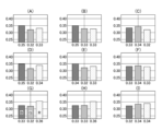
- FIG. 2 shows graphs (A) to (I) corresponding to the luminance intensity ratios of wavelength U, wavelength V, and wavelength W in regions (A) to (I) of the image 507 .
- the luminance intensity ratio in the regions (A) to (I) is uniform.
- image 501 U wavelength image
- image 503 V wavelength image
- image 505 W wavelength image
- the intensity ratios of the luminances between are also equal.
- the surrounding environment when the images 501, 503, and 505 were actually captured differs from the surrounding environment when the mixing ratio was measured.
- the image 501, the image 503, and the image 505 have different luminance intensity ratios.
- the luminance intensity ratios among the images 501, 503, and 505 are not equal (for example, in region (E), the difference in intensity ratio between the images 501, 503, and 505 is about 2%. ).
- the surrounding environment differs between when the mixing ratio is measured and when the actual image is captured, which may cause flares and the like to change, making it impossible to acquire accurate wavelength images (maintaining wavelength reproducibility).
- 3 and 4 are diagrams for explaining a second example in which the wavelength image becomes inaccurate due to changes in the surrounding environment.
- a black object 519 is imaged against a background of a white plate having uniform reflection characteristics.
- Image 511 is a U wavelength image of wavelength U
- image 513 is a V wavelength image of wavelength V
- image 515 is a W wavelength image of wavelength W.
- An image 517 is a pseudo-color image generated under the same conditions as those described with reference to FIG. FIG. 4 shows graphs (A) to (I) corresponding to the luminance intensity ratios of wavelength U, wavelength V, and wavelength W in regions (A) to (I) of the image 517 .
- the surrounding environment when the images 511, 513, and 515 were captured differs from the surrounding environment when the mixing ratio was measured.
- the image 513 and the image 515 have different luminance intensity ratios.
- the luminance intensity ratios among the images 511, 513, and 515 are not equal (for example, in region (E), the amount of difference in luminance intensity ratio between the images 511, 513, and 515 is approximately 6%).
- FIG. 5 is a flow chart showing the imaging method of the present invention. Each step of the imaging method described below is performed by processor 142 of multispectral camera 100 (FIG. 20). Also, the processor 142 executes each step by executing a dedicated program for the imaging method stored in the memory 144 .
- the processor 142 acquires spectral data of the background 2, the first subject 3, and the second subject 4.
- the processor 142 selects a plurality of wavelengths from the wavelength bands (wavelength bands) of the spectrum data of the background 2, first subject 3, and second subject 4.
- FIG. In this example, the first wavelength ⁇ (1), the second wavelength ⁇ (2), and the third wavelength ⁇ (3) are selected.
- the processor 142 uses the first wavelength ⁇ (1), the second wavelength ⁇ (2), and the third wavelength ⁇ (3) to A subject including at least one of the second subjects 4 is imaged.
- processor 142 acquires spectral data of the objects (background 2, first object 3, and second object 4).
- FIG. 6 is a schematic diagram showing subjects (first subject, second subject, and background (third subject)) captured by the multispectral camera 100.
- FIG. 6 is a schematic diagram showing subjects (first subject, second subject, and background (third subject)) captured by the multispectral camera 100.
- the subject consists of a first subject 3, a second subject 4, and a background 2.
- a multispectral camera 100 images an object including at least one of a background 2, a first object 3, and a second object 4 to identify the first object 3 and the second object 4 located on the background 2. Sensing is performed. Accordingly, processor 142 obtains spectral data regarding the reflectance of background 2 , first object 3 , and second object 4 .
- FIG. 7 and 8 are diagrams showing spectrum data of the background 2, the first subject 3, and the second subject 4.
- FIG. 7 and 8 are diagrams showing spectrum data of the background 2, the first subject 3, and the second subject 4.
- Spectral data SD1 first spectral data
- spectral data SD2 second spectral data
- spectral data SD3 third spectral data
- the wavelength ranges of spectrum data SD1, spectrum data SD2, and spectrum data SD3 acquired by processor 142 are wavelength ranges in which the wavelength range of spectrum data SD1 and the wavelength range of spectrum data SD2 overlap. That is, in the case shown in FIG.
- the wavelength range of the spectrum data SD1 and the spectrum data SD2 is from 400 nm to 1000 nm
- the spectrum data SD3 is from 400 nm to 1000 nm
- the wavelength range of the spectrum data SD1 to SD3 is from 400 nm to 1000 nm. They overlap at 1000 nm. Therefore, processor 142 acquires spectral data SD1-SD3 in the wavelength range of 400 nm-1000 nm.
- the reflectance corresponding to each wavelength of the background 2, the first subject 3, and the second subject 4 is displayed as spectral data in the same manner as in FIG. , the spectrum data SD2 corresponds to the second object 4, and the spectrum data SD3 corresponds to the background 2.
- FIG. 8 the reflectance corresponding to each wavelength of the background 2, the first subject 3, and the second subject 4 is displayed as spectral data in the same manner as in FIG. , the spectrum data SD2 corresponds to the second object 4, and the spectrum data SD3 corresponds to the background 2.
- the wavelength regions of the spectrum data SD1 and the spectrum data SD2 overlap from 550 nm to 1000 nm. Therefore, the wavelength range of 550 nm to 1000 nm is sufficient for the spectrum data SD3, and the processor 142 obtains the spectrum data SD1 to SD3 in the wavelength range of 550 nm to 1000 nm.
- the processor 142 acquires spectral data SD1-SD3 in various forms.
- the spectral data SD1 to SD3 may be acquired by imaging the background 2, the first subject 3, and the second subject 4 with a hyperspectral camera and input to the multispectral camera 100.
- the spectral data SD1-SD3 may be selected from a database in which various spectral data are stored and input to the multispectral camera 100 for acquisition by the processor 142.
- the spectral data SD1 to SD3 may be stored in advance in the memory 144 of the multispectral camera 100 and the processor 142 may acquire them.
- the processor 142 In wavelength acquisition selection, the processor 142, based on the acquired spectral data SD1, spectral data SD2, and spectral data SD3, selects a first wavelength ⁇ (1), a second wavelength ⁇ (2), and a third wavelength ⁇ (3). to select.
- the processor 142 selects a plurality of wavelengths by obtaining at least two or more factors using the difference or the ratio of the feature amounts of the two spectral data out of the spectral data SD1, the spectral data SD2, and the spectral data SD3 as factors.
- the difference in feature amount (reflectance) of spectral data is used as a factor.
- the spectrum data SD1 the spectrum data SD2, and the spectrum data SD3 described with reference to FIG. 7, at least a wavelength (reference wavelength ) and different wavelengths. Therefore, conventionally, for example, 420 nm has been selected as at least the second wavelength ⁇ (2) (reference wavelength), and 500 nm has been selected as the first wavelength ⁇ (1).
- the processor 142 calculates the reflectance difference (first factor) between the spectrum data SD3 and the spectrum data SD1 and the reflectance difference (second factor) between the spectrum data SD3 and the spectrum data SD2. Based on the relationship, a first wavelength ⁇ (1), a second wavelength ⁇ (2) and a third wavelength ⁇ (3) are selected. For example, the processor 142 selects 850 nm as the second wavelength ⁇ (2) (reference wavelength) at which the first and second factors are minimum. Note that the processor 142 may select a wavelength that minimizes at least one of the first factor and the second factor as the reference wavelength.
- the processor 142 sets the first wavelength ⁇ (1) to 925 nm, which is larger than the second wavelength ⁇ (2) and allows discrimination between the first subject 3 and the second subject 4. Select as For example, as the first wavelength ⁇ (1), a wavelength that maximizes the sum of the first factor and the second factor within a predetermined range (15% or 5%) described below may be selected. Processor 142 also selects third wavelength ⁇ (3) as 875 nm between first wavelength ⁇ (1) and second wavelength ⁇ (2).
- the processor 142 determines that the first factor (difference in reflectance between spectrum data SD3 and SD1) and the second factor (difference in reflectance between spectrum data SD3 and SD2) are within a range of 15%.
- a certain first wavelength ⁇ (1) to third wavelength ⁇ (3) can be selected.
- the processor 142 selects the first wavelength ⁇ (1) to the third wavelength ⁇ (3) that satisfy the following equations.
- ⁇ is the reflectance ⁇ 1 to ⁇ 3 of the first object 3 at the first wavelength ⁇ (1) to the third wavelength ⁇ (3) respectively, and ⁇ is the first wavelength ⁇ (1) to the third wavelength ⁇ (3).
- the reflectances ⁇ 1 to ⁇ 3 of the background 2 at the wavelength ⁇ (3) are input, and the reflectances ⁇ 1 to ⁇ 3 of the second object 4 at the first wavelength ⁇ (1) to the third wavelength ⁇ (3) are input as ⁇ . be done.
- ( ⁇ ) and ( ⁇ ) at the second wavelength are smaller than the corresponding values of the first wavelength ⁇ (1) and the third wavelength ⁇ (3), the first wavelength ⁇ (1) ⁇ third wavelength ⁇ (3) is selected (Condition 1).
- FIG. 9 is a diagram showing a case where Expression (5), Expression (6), and Condition 1 are satisfied. Note that FIG. 9 shows spectrum data SD1 to SD3 and first wavelength ⁇ (1) to third wavelength ⁇ (3).
- the difference M1, the difference N1, the difference M2 (not shown because it is 0), the difference N2 (not shown because it is 0), the difference M3, and the first wavelength ⁇ where the difference N3 is within 15% (1) to ⁇ (3) are selected. Furthermore, as the difference M2 and the difference N2, the first wavelength ⁇ (1) to the third wavelength ⁇ (3), which are smaller than the difference M1, the difference N1, the difference M3, and the difference N3, are selected.
- the processor 142 sets the first factor (difference in reflectance between spectral data SD3 and SD1) and second factor (difference in reflectance between spectral data SD3 and SD2) to 5%. can be selected from the first wavelength ⁇ (1) to the third wavelength ⁇ (3) within the range of .
- the processor 142 selects the first wavelength ⁇ (1) to the third wavelength ⁇ (3) that satisfy the following equations.
- ⁇ is the reflectance ⁇ 1 to ⁇ 3 of the first object 3 at the first wavelength ⁇ (1) to the third wavelength ⁇ (3) respectively, and ⁇ is the first wavelength ⁇ (1) to the third wavelength ⁇ (3).
- the reflectances ⁇ 1 to ⁇ 3 of the background 2 at the wavelength ⁇ (3) are input, and the reflectances ⁇ 1 to ⁇ 3 of the second object 4 at the first wavelength ⁇ (1) to the third wavelength ⁇ (3) are input as ⁇ . be done.
- ( ⁇ ) and ( ⁇ ) at the second wavelength are smaller than the corresponding values of the first wavelength ⁇ (1) and the third wavelength ⁇ (3), the first wavelength ⁇ (1) ⁇ third wavelength ⁇ (3) is selected (Condition 1).
- the processor 142 selects the first wavelength ⁇ (1) to the third wavelength ⁇ (3) by factors based on the spectrum data SD1 to SD3. Accordingly, since the difference from the reflectance of the background 2 is within a certain range, the influence of changes in the surrounding environment can be suppressed.
- the processor 142 may select the first wavelength ⁇ (1) to the third wavelength ⁇ (3) according to another mode.
- the processor 142 causes the acquired spectral data SD1 to SD3 to be displayed on the display provided on the back of the multispectral camera 100, and the user can select the first wavelength ⁇ (1) to the third wavelength ⁇ (3) from the display. ), and the processor 142 selects the first wavelength ⁇ (1) to the third wavelength ⁇ (3) based on instructions from the user input via the operation unit (not shown) of the multispectral camera 100.
- the processor 142 captures the first object 3, the second object 4, the background 2 (the third object ) is captured.
- FIG. 10 is a diagram for explaining the imaging process by the multispectral camera 100.
- FIG. FIG. 10 shows a specific example in which the background 2 is a conveyor belt, and the first subject 3 and the second subject 4 are placed on it and are continuously carried.
- the multispectral camera 100 images a first object 3 and a second object 4 that are continuously conveyed.
- the processor 142 causes the multispectral camera 100 to image the scene of the first subject 3 and the second subject 4 located on the background 2 .
- the multispectral camera 100 sometimes captures a scene with only the background 2, a scene with only the first subject 3 positioned on the background 2, and a scene with only the second subject 4 positioned on the background 2.
- the multispectral camera 100 is set so as to acquire first to third wavelength images corresponding to the first to third wavelengths ⁇ (1) to ⁇ (3) selected in the wavelength selection step.
- the illumination device 10 illuminates the background 2, the first subject 3, and the second subject 4 in accordance with the imaging by the multispectral camera 100 or all the time (illumination step).
- the illumination device 10 uses a light source a, a light source b, or a light source in which the light source a and the light source b are mixed.
- the illumination device 10 should be a shadowless illumination device. is preferred.
- the multispectral camera 100 performs interference elimination processing on the acquired first to third wavelength images as necessary.
- the multispectral camera 100 performs sensing for identifying the first subject 3 and the second subject 4 (detecting their existence, etc.) based on the captured first to third wavelength images.
- the reflectances of the first subject 3, the second subject 4, and the background 2 are Since the first wavelength ⁇ (1) to the third wavelength ⁇ (3) are selected for which the factor of is within a predetermined range, the influence of changes in the surrounding environment is suppressed, and high wavelength reproducibility is maintained. Acquisition can be performed.
- This embodiment includes an intensity ratio measurement step and a correction step (first correction step) in addition to the imaging method of the first embodiment described above.
- FIG. 11 is a flowchart showing the imaging method of this embodiment.
- the imaging method described below is performed by processor 142 of multispectral camera 100 .
- the processor 142 executes each step by executing a dedicated program for the imaging method stored in the memory 144 .
- the processor 142 acquires spectral data of the background 2, the first subject 3, and the second subject 4.
- the processor 142 selects the first wavelength ⁇ (1), the second wavelength ⁇ ( 2) Select a third wavelength ⁇ (3).
- the processor 142 images the background 2 with the first wavelength ⁇ (1), the second wavelength ⁇ (2), and the third wavelength ⁇ (3), and Wavelength images (image data) of the first wavelength ⁇ (1), the second wavelength ⁇ (2), and the third wavelength ⁇ (3) of 2 are acquired, and the first wavelength ⁇ (1) to the third wavelength ⁇ (1) are obtained in a plurality of regions.
- the intensity ratio of luminance of three wavelengths ⁇ (3) is measured.
- the processor 142 uses the first wavelength ⁇ (1), the second wavelength ⁇ (2), and the third wavelength ⁇ (3) to A subject including at least one of the second subjects 4 is imaged.
- the processor 142 corrects the intensity ratios of the multiple regions based on the first intensity ratio, which is one of the measured intensity ratios.
- the processor 142 measures the luminance intensity ratio of the background 2 using the first wavelength ⁇ (1) to the third wavelength ⁇ (3). Specifically, the processor 142 captures only the background 2 with the multispectral camera 100 at the first wavelength ⁇ (1) to the third wavelength ⁇ (3) to acquire the first to third wavelength images. .
- FIG. 12 is a diagram explaining the imaging of the background 2 in the intensity ratio measurement process.
- the background 2 is imaged by the multispectral camera 100, and a first wavelength image, a second wavelength image, and a third wavelength image of the background 2 are acquired.
- the background 2 imaged here is the same as the background 2 imaged in the imaging process.
- a white plate having uniform reflectance at the first wavelength ⁇ (1), the second wavelength ⁇ (2), and the third wavelength ⁇ (3) is used.
- background 2 uses a chart in which the intensity ratios at the first wavelength ⁇ (1), the second wavelength ⁇ (2), and the third wavelength ⁇ (3) are constant in a plurality of regions.
- the illumination device 10 is an illumination device used in the imaging process. Note that the same light source is preferably used in the intensity ratio measurement process and the imaging process.
- FIG. 13 and 14 are diagrams for explaining the intensity ratio of the brightness of the background 2 measured in the intensity ratio measurement process and the calculated first correction coefficient.
- FIG. 13 shows the measurement results obtained with the light source a
- FIG. 14 shows the measurement results obtained with the light source b.
- a pseudo-color image 101 (FIG. 13) is generated based on the first to third wavelength images. Specifically, the luminance intensity ratio of the first wavelength image is red (R: RED), the luminance intensity ratio of the second wavelength image is blue (B: BLUE), and the luminance intensity ratio of the third wavelength image is green.
- a pseudo-color image 101 is generated by superimposing with (G: GREEN).
- Reference numeral 105 denotes luminance intensity at the first wavelength ⁇ (1), the second wavelength ⁇ (2), and the third wavelength ⁇ (3) in the regions (A) to (I) of the pseudo-color image 101. The ratios are shown correspondingly in graphs (A)-(I).
- the luminance intensity ratios shown in graphs (A) to (I) are averages or representative values of the luminance intensity ratios of the regions (A) to (I).
- the processor 142 performs the first correction to align the luminance intensity ratios at the first wavelength ⁇ (1), the second wavelength ⁇ (2), and the third wavelength ⁇ (3) in the regions (A) to (I). Get coefficients.
- the processor 142 converts the luminance intensity ratio (first intensity ratio) of the central area (E) of the pseudo-color image 101 to the area (A) to area (D) and area (F) to area (I).
- a first correction factor for adjusting the intensity ratio is obtained.
- the pseudo-color image 103 is obtained by applying the first correction factor to the pseudo-color image 101 .
- the pseudo-color image 103 has a uniform luminance intensity ratio, as indicated by graphs (A) to (I) indicated by reference numeral 107 . That is, the first correction coefficient makes the luminance intensity ratios of the regions (A) to (I) the same.
- a pseudo-color image 109 (FIG. 14), like the pseudo-color image 101, is generated based on the first to third wavelength images.
- Reference numeral 113 denotes the luminance intensity ratio at the first wavelength ⁇ (1), the second wavelength ⁇ (2), and the third wavelength ⁇ (3) of the regions (A) to (I) of the pseudo-color image 109. are shown in graphs (A) to (I).
- the processor 142 converts the luminance intensity ratio (first intensity ratio) of the central area (E) of the pseudo-color image 109 to the area (A) to area (D) and area (F) to area (I).
- a first correction factor for adjusting the intensity ratio is obtained.
- Applying the first correction factor to pseudo-color image 109 results in pseudo-color image 111 .
- the pseudo-color image 111 has a uniform luminance intensity ratio, as indicated by graphs (A) to (I) indicated by reference numeral 115 . That is, the luminance intensity ratio of the regions (A) to (I) becomes uniform by the first correction coefficient.
- the intensity ratio of the luminance of the first wavelength ⁇ (1) to the third wavelength ⁇ (3) of the background 2 is measured, and based on the measurement result, the first correction coefficient is calculated.
- the first correction coefficient may be obtained for each pixel of the image, or the first correction coefficient may be obtained for a larger or smaller region.
- the processor 142 applies the first correction coefficient acquired in the intensity ratio measurement step to the first wavelength image, the second wavelength image, and the third wavelength image captured in the imaging step. Then, the luminance intensity ratio of the regions (A) to (I) is corrected.
- the first correction coefficient is preferably applied to the entire first to third wavelength images. image data) may be applied with the first correction factor. The influence of changes in the surrounding environment is suppressed in the first, second, and third wavelength images corrected with the first correction coefficient. Therefore, the first to third wavelength images can be obtained while maintaining wavelength reproducibility, and accurate sensing can be performed.
- This embodiment includes a correction step (second correction step) in addition to the imaging method of the second embodiment described above.
- FIG. 15 is a flowchart showing the imaging method of this embodiment.
- the imaging method described below is performed by processor 142 of multispectral camera 100 .
- the processor 142 executes each step by executing a dedicated program for the imaging method stored in the memory 144 .
- the processor 142 acquires spectral data of the background 2, the first subject 3, and the second subject 4.
- the processor 142 selects the first wavelength ⁇ (1), the second wavelength ⁇ (2 ), and select the third wavelength ⁇ (3).
- the processor 142 images the background 2 with the first wavelength ⁇ (1), the second wavelength ⁇ (2), and the third wavelength ⁇ (3), and Wavelength images (image data) of the first wavelength ⁇ (1), the second wavelength ⁇ (2), and the third wavelength ⁇ (3) of 2 are acquired, and the intensity ratio of the luminance of multiple wavelengths in multiple regions is calculated. measure.
- the processor 142 uses the first wavelength ⁇ (1), the second wavelength ⁇ (2), and the third wavelength ⁇ (3) to A subject including at least one of the second subjects 4 is imaged.
- the processor 142 corrects the intensity ratios of the multiple regions based on the first intensity ratio, which is one of the intensity ratios measured in the intensity ratio measurement step.
- the processor 142 performs correction to reduce the difference in the intensity ratios measured in the intensity ratio measurement step.
- the second correction coefficient is calculated in addition to the first correction coefficient.
- the first correction coefficient and the second correction coefficient are calculated separately will be described, but the present invention is not limited to this.
- a correction coefficient that is a combination of the first correction coefficient and the second correction coefficient may be calculated.
- 16 and 17 are diagrams for explaining the intensity ratio of the brightness of the background 2 measured in the intensity ratio measurement process and the calculated first correction coefficient and second correction coefficient. 13 and 14 are denoted by the same reference numerals, and description thereof will be omitted.
- the second correction coefficient is a correction coefficient that reduces the difference in the luminance intensity ratio of each wavelength in the regions (A) to (I).
- the second correction coefficient is a correction coefficient that equalizes the intensity of luminance between the first wavelength ⁇ (1) to the third wavelength ⁇ (3) in the regions (A) to (I).
- the luminance intensity ratios of the regions (A) to (I) are uniform due to the first correction coefficient.
- the luminance intensity ratios of the first wavelength ⁇ (1) to the third wavelength ⁇ (3) are not uniform.
- the intensity ratios are 0.33, 0.32, and 0.35.
- this non-uniform intensity ratio is corrected to be uniform to 0.33, 0.33, and 0.33.
- the second correction coefficients are similarly calculated for other regions.
- a pseudo-color image 151 is obtained by applying the second correction factor to the pseudo-color image 103 . Areas (A) to (I) of the pseudo-color image 151 have luminance intensity ratios of 0.33, 0.32, and 0.35 as indicated by reference numeral 153 .
- the pseudo-color image 151 will show the original white color of the background 2 .
- the luminance intensity ratio of the first wavelength ⁇ (1) to the third wavelength ⁇ (3) is not uniform as shown in graphs (A) to (I) of reference numeral 115. .
- the intensity ratios are 0.34, 0.34, 0.32, but by applying the second correction factor, they are reduced to 0.33, 0. 0.33 and 0.33 are corrected.
- a pseudo-color image 155 is obtained by applying the second correction factor to the pseudo-color image 111 .
- Areas (A) to (I) of the pseudo-color image 155 have luminance intensity ratios of 0.33, 0.32, and 0.35 as indicated by reference numeral 157 . Pseudo-color image 155 will now show the original white color of background 2 .
- the intensity ratio of the luminance of the first wavelength ⁇ (1) to the third wavelength ⁇ (3) of the background 2 is measured, and based on the measurement result, the first correction coefficient and a second correction factor are calculated.
- the second correction coefficient may be obtained for each pixel of the image, or the second correction coefficient may be obtained for a larger area or a smaller area.
- the processor 142 uses the second correction coefficient acquired in the intensity ratio measurement step to convert the first wavelength image, the second wavelength image, and the third wavelength image captured in the imaging step.
- a second correction factor is applied to the image to correct the intensity ratio of area (A) to area (I).
- the second correction coefficient is preferably applied to the entire first to third wavelength images.
- image data may be applied with a second correction factor.
- the processor 142 can perform highly accurate sensing by correcting the sensitivity of the image sensor 130 (FIG. 20) based on the first correction coefficient and/or the second correction coefficient.
- ⁇ Other Embodiment 1> In the above-described embodiment, an example has been described in which three different first wavelength ⁇ (1), second wavelength ⁇ (2), and third wavelength ⁇ (3) are selected in the wavelength selection process. However, the number of wavelengths selected in the wavelength selection process is not limited to three wavelengths as long as a plurality of wavelengths are selected. For example, in the wavelength selection step, two wavelengths may be selected, or the first wavelength ⁇ (1) and the second wavelength ⁇ (2) described above may be selected.
- the processor 142 determines that the first factor (difference in reflectance between spectral data SD3 and SD1) and the second factor (difference in reflectance between spectral data SD3 and SD2) are within a range of 15%.
- the processor 142 selects a first wavelength ⁇ (1) and a second wavelength ⁇ (2) that satisfy the following equations.
- ⁇ is the reflectance ⁇ 1 and ⁇ 2 of the first object 3 at the first wavelength ⁇ (1) and the second wavelength ⁇ (2) respectively, and ⁇ is the first wavelength ⁇ (1) and the second wavelength ⁇ (2).
- the reflectances ⁇ 1 and ⁇ 2 of the background 2 at two wavelengths ⁇ (2) are input, respectively, and ⁇ is the reflectance ⁇ 1 and ⁇ 2 of the second object 4 at the first wavelength ⁇ (1) and the second wavelength ⁇ (2). each is entered.
- ( ⁇ ) and ( ⁇ ) at the second wavelength are smaller than the corresponding values of the first wavelength ⁇ (1), the first wavelength ⁇ (1) and the second wavelength ⁇ (2) is selected (condition 2).
- the processor 142 sets the first factor (difference in reflectance between spectral data SD3 and SD1) and second factor (difference in reflectance between spectral data SD3 and SD2) to 5%.
- a first wavelength ⁇ (1) and a second wavelength ⁇ (2) can be chosen that are within the range of .
- the processor 142 selects a first wavelength ⁇ (1) and a second wavelength ⁇ (2) that satisfy the following equations.
- ⁇ is the reflectance ⁇ 1 and ⁇ 2 of the first object 3 at the first wavelength ⁇ (1) and the second wavelength ⁇ (2) respectively, and ⁇ is the first wavelength ⁇ (1) and the second wavelength ⁇ (2).
- the reflectances ⁇ 1 and ⁇ 2 of the background 2 at two wavelengths ⁇ (2) are input, respectively, and ⁇ is the reflectance ⁇ 1 and ⁇ 2 of the second object 4 at the first wavelength ⁇ (1) and the second wavelength ⁇ (2). each is entered.
- ( ⁇ - ⁇ ) and ( ⁇ - ⁇ ) at the second wavelength ⁇ (2) are smaller than the corresponding values of the first wavelength ⁇ (1), the first wavelength ⁇ (1) and the second wavelength ⁇ (2) is selected (Condition 2).
- two wavelengths (first wavelength ⁇ (1) and second wavelength ⁇ (2) are selected in the wavelength selection step. is selected and imaging is performed, it is possible to acquire the number of wavelength images desired by the user.
- the background 2 was a predetermined white plate.
- the processor 142 notifies the optimum background based on the reflectance (spectral data) of the first subject 3 and the second subject 4 (notification step).
- the memory 144 of the multispectral camera 100 of the present embodiment stores the spectrum data of each of the multiple replacement subjects (multiple backgrounds) that can be replaced with the background 2 and the multiple replacement subjects. Based on the spectral data SD1 of the first subject 3 and the spectral data SD2 of the second subject 4, the processor 142 notifies one replacement subject (background) among the multiple replacement subjects as a recommended background. Note that the processor 142 can notify the replacement subject on a display unit (not shown) provided on the back surface of the multispectral camera 100 .
- the multispectral camera 100 may also include a background display device 150 that variably displays the background 2 (see FIG. 20).
- the background display device 150 is composed of, for example, a liquid crystal display or the like under the control of the processor 142, and can display a desired color as the background (third subject variable display step). In this way, by changing the background color on the background display device 150, when objects with completely different spectral reflectances are detected at the same time, the background color can be changed for each place, or the multispectral display with the same setting can be performed.
- the background color can be easily changed when it is desired to use the camera 100 for a different purpose (for example, detection of another subject).
- Figures 18 and 19 are diagrams explaining examples of recommended backgrounds.
- FIG. 18 shows recommended background spectral data SD4 (fourth spectral data). Based on the spectrum data SD1 of the first subject 3 and the spectrum data SD2 of the second subject 4, the background having the spectrum data SD4 is selected as a recommended subject and notified.
- the spectrum data SD4 has a small difference in reflectance between the spectrum data SD1 and the spectrum data SD2 in the wavelength range of 400 nm to 1000 nm. By using the background having such spectral data SD4, it is possible to select multiple wavelengths for imaging with the multispectral camera 100 in a wide wavelength range.
- FIG. 19 shows recommended background spectral data SD5.
- the background having the spectrum data SD5 is selected as a recommended subject and notified. Since the spectral data SD5 intersects the spectral data SD1 and the spectral data SD2 at a plurality of points, it has a plurality of points where the difference in reflectance from the spectral data SD1 and the spectral data SD2 is small.
- imaging can be performed at a plurality of locations (wavelength ranges).
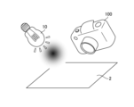
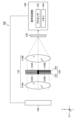
- FIG. 20 is a schematic diagram showing an example of a multispectral camera 100 used in the imaging method of the present invention.
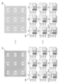
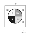
- FIG. 21 is a schematic diagram showing an example of the filter unit 120 included in the multispectral camera 100. As shown in FIG.
- the multispectral camera 100 shown in FIG. 20 is composed of a photographing optical system 110 including lenses 110A and 110B and a filter unit 120, an image sensor (imaging device) 130, and a signal processing section 140.
- a background display device 150 may also be connected to the multispectral camera 100 .
- the background display device 150 is connected to the signal processing section 140 and controlled by the processor 142 .
- a band-pass filter unit 124 included in the filter unit 120 (FIG. 21) has a first wavelength ⁇ (1), a second wavelength ⁇ (2), a third A first band-pass filter (first wavelength selection element) 124A, a second band-pass filter (second wavelength selection element) 124B, and a third band-pass that transmit light in a wavelength band centered at wavelength ⁇ (3). It is composed of a filter (third wavelength selection element) 124C.
- the filter unit 120 has four pupil regions (first pupil region to fourth pupil region), and the unused fourth pupil region is shielded by the shielding member B (see FIG. 21).
- the filter unit 120 is composed of a polarizing filter unit 122 and a bandpass filter unit 124 and is preferably arranged at or near the pupil position of the imaging optical system 110 .
- the polarizing filter unit 122 includes a first polarizing filter 122A, a second polarizing filter 122B, a third It consists of a polarizing filter 122C.
- the first polarizing filter 122A has a polarizing direction of 0°
- the second polarizing filter 122B has a polarizing direction of 90°
- the third polarizing filter 122C has a polarizing direction of 45°.
- the band-pass filter unit 124 includes a first band-pass filter 124A and a second band-pass filter 124B that select wavelength regions of light that passes through the first, second, and third pupil regions of the imaging optical system 110, respectively. , and a third bandpass filter 124C. Therefore, the light transmitted through the first pupil region of the imaging optical system 110 is linearly polarized by the first polarizing filter 122A, and is filtered by the first band-pass filter 124A only in the wavelength range including the first wavelength ⁇ (1). To Penetrate.
- the light passing through the second pupil region of the imaging optical system 110 is linearly polarized by the second polarizing filter 122B (linearly polarized in a direction different from that of the first polarizing filter 122A by 90°), and is further polarized by the second bandpass filter 124B. Therefore, only light in a wavelength range including the second wavelength ⁇ (2) is transmitted. Further, the light passing through the third pupil region of the imaging optical system 110 is linearly polarized by the third polarizing filter 122C, and only the light in the wavelength region including the third wavelength ⁇ (3) is filtered by the third bandpass filter 124C. To Penetrate.
- the image sensor 130 includes a plurality of pixels composed of photoelectric conversion elements arranged two-dimensionally, and a first polarizing filter, a second polarizing filter, and a third polarizing filter having polarization directions of 0°, 45°, and 90°. It is arranged and configured regularly.
- the first polarizing filter 122A and the first polarizing filter of the image sensor 130 have the same polarizing direction
- the second polarizing filter 122B and the second polarizing filter of the image sensor 130 have the same polarizing direction
- the third polarizing filter has the same polarization direction
- the polarizing filter 122C and the third polarizing filter of the image sensor 130 have the same polarization direction.
- the signal processing unit 140 reads pixel signals from the pixels of the image sensor 130 in which the first polarizing filters are arranged, thereby obtaining a first wavelength image of a narrow band wavelength-selected by the first band-pass filter 124A.
- a second wavelength image of a narrow band wavelength-selected by the second band-pass filter 124B is acquired, and the third polarizing filter of the image sensor 130 is obtained.
- a third wavelength image of a narrow band wavelength-selected by the third band-pass filter 124C is obtained.
- the first wavelength image, the second wavelength image, and the third wavelength image acquired by the signal processing unit 140 are images suitable for separating the first subject 3 and the second subject 4 .
- a composite image with enhanced dynamic range and enhanced sensing performance can be created.
- interference elimination processing of the first wavelength image, the second wavelength image, and the third wavelength image is performed as necessary.
- the hardware structure of the processing unit that executes various processes is the following various processors.
- the circuit configuration can be changed after manufacturing, such as CPU (Central Processing Unit), FPGA (Field Programmable Gate Array), which is a general-purpose processor that executes software (program) and functions as various processing units.
- Programmable Logic Device PLD
- ASIC Application Specific Integrated Circuit
- One processing unit may be composed of one of these various processors, or composed of two or more processors of the same type or different types (for example, a plurality of FPGAs, or a combination of a CPU and an FPGA).
- a plurality of processing units may be configured by one processor.
- a processor functions as multiple processing units.
- SoC System On Chip
- SoC System On Chip
- the hardware structure of these various processors is, more specifically, an electrical circuit that combines circuit elements such as semiconductor elements.
- Second Subject 10 Illumination Device 100: Multispectral Camera 110: Shooting Optical System 110A: Lens 110B: Lens 120: Filter Unit 122: Polarizing Filter Unit 122A: First Polarizing Filter 122B: Second polarizing filter 122C: Third polarizing filter 124: Bandpass filter unit 124A: First bandpass filter 124B: Second bandpass filter 124C: Third bandpass filter 130: Image sensor 140: Signal processing unit 142: Processor 144 : Memory 150 : Background display device
Landscapes
- Engineering & Computer Science (AREA)
- Multimedia (AREA)
- Signal Processing (AREA)
- Physics & Mathematics (AREA)
- Spectroscopy & Molecular Physics (AREA)
- General Physics & Mathematics (AREA)
- Color Television Image Signal Generators (AREA)
- Investigating Or Analysing Materials By Optical Means (AREA)
Priority Applications (3)
| Application Number | Priority Date | Filing Date | Title |
|---|---|---|---|
| CN202280047061.6A CN117651851A (zh) | 2021-07-30 | 2022-06-13 | 摄像方法及程序 |
| JP2023538318A JPWO2023007965A1 (https=) | 2021-07-30 | 2022-06-13 | |
| US18/399,753 US12425705B2 (en) | 2021-07-30 | 2023-12-29 | Imaging method and program |
Applications Claiming Priority (2)
| Application Number | Priority Date | Filing Date | Title |
|---|---|---|---|
| JP2021125278 | 2021-07-30 | ||
| JP2021-125278 | 2021-07-30 |
Related Child Applications (1)
| Application Number | Title | Priority Date | Filing Date |
|---|---|---|---|
| US18/399,753 Continuation US12425705B2 (en) | 2021-07-30 | 2023-12-29 | Imaging method and program |
Publications (1)
| Publication Number | Publication Date |
|---|---|
| WO2023007965A1 true WO2023007965A1 (ja) | 2023-02-02 |
Family
ID=85086646
Family Applications (1)
| Application Number | Title | Priority Date | Filing Date |
|---|---|---|---|
| PCT/JP2022/023585 Ceased WO2023007965A1 (ja) | 2021-07-30 | 2022-06-13 | 撮像方法及びプログラム |
Country Status (4)
| Country | Link |
|---|---|
| US (1) | US12425705B2 (https=) |
| JP (1) | JPWO2023007965A1 (https=) |
| CN (1) | CN117651851A (https=) |
| WO (1) | WO2023007965A1 (https=) |
Citations (8)
| Publication number | Priority date | Publication date | Assignee | Title |
|---|---|---|---|---|
| JP2003130811A (ja) * | 2001-10-25 | 2003-05-08 | Dainippon Screen Mfg Co Ltd | 波長選択機能を利用した検査対象物の検査 |
| US20080002185A1 (en) * | 2006-06-08 | 2008-01-03 | Anatoly Gitelson | System and methods for non-destructive analysis |
| JP2014075699A (ja) * | 2012-10-04 | 2014-04-24 | Canon Inc | 動画再生装置、表示制御方法、プログラム及び記憶媒体 |
| JP2017053699A (ja) * | 2015-09-09 | 2017-03-16 | 国立大学法人岐阜大学 | 物質判別に用いる近赤外画像撮像用の波長決定方法および近赤外画像を用いた物質判別方法 |
| JP2017064405A (ja) * | 2015-09-29 | 2017-04-06 | 住友電気工業株式会社 | 光学測定装置及び光学測定方法 |
| CN207114406U (zh) * | 2017-07-28 | 2018-03-16 | 合肥美亚光电技术股份有限公司 | 多光谱成像装置及多光谱相机 |
| JP2018189565A (ja) * | 2017-05-09 | 2018-11-29 | 株式会社キーエンス | 画像検査装置 |
| JP2020165666A (ja) * | 2019-03-28 | 2020-10-08 | セイコーエプソン株式会社 | 分光検査方法および分光検査装置 |
Family Cites Families (4)
| Publication number | Priority date | Publication date | Assignee | Title |
|---|---|---|---|---|
| KR20030026839A (ko) | 2001-09-26 | 2003-04-03 | 다이닛뽕스크린 세이조오 가부시키가이샤 | 화상처리를 이용한 검사대상물의 표면검사방법 및 그 장치 |
| JP3960989B2 (ja) | 2004-07-16 | 2007-08-15 | オリンパス株式会社 | 色推定システム及び色推定方法 |
| EP4250723B1 (en) * | 2020-12-16 | 2025-05-21 | Huawei Technologies Co., Ltd. | Image generation method and apparatus, and electronic device |
| US20240233187A1 (en) * | 2021-10-18 | 2024-07-11 | Sun's Arrow Research, Inc. | Color Calibration Systems and Pipelines for Digital Images |
-
2022
- 2022-06-13 WO PCT/JP2022/023585 patent/WO2023007965A1/ja not_active Ceased
- 2022-06-13 CN CN202280047061.6A patent/CN117651851A/zh active Pending
- 2022-06-13 JP JP2023538318A patent/JPWO2023007965A1/ja active Pending
-
2023
- 2023-12-29 US US18/399,753 patent/US12425705B2/en active Active
Patent Citations (8)
| Publication number | Priority date | Publication date | Assignee | Title |
|---|---|---|---|---|
| JP2003130811A (ja) * | 2001-10-25 | 2003-05-08 | Dainippon Screen Mfg Co Ltd | 波長選択機能を利用した検査対象物の検査 |
| US20080002185A1 (en) * | 2006-06-08 | 2008-01-03 | Anatoly Gitelson | System and methods for non-destructive analysis |
| JP2014075699A (ja) * | 2012-10-04 | 2014-04-24 | Canon Inc | 動画再生装置、表示制御方法、プログラム及び記憶媒体 |
| JP2017053699A (ja) * | 2015-09-09 | 2017-03-16 | 国立大学法人岐阜大学 | 物質判別に用いる近赤外画像撮像用の波長決定方法および近赤外画像を用いた物質判別方法 |
| JP2017064405A (ja) * | 2015-09-29 | 2017-04-06 | 住友電気工業株式会社 | 光学測定装置及び光学測定方法 |
| JP2018189565A (ja) * | 2017-05-09 | 2018-11-29 | 株式会社キーエンス | 画像検査装置 |
| CN207114406U (zh) * | 2017-07-28 | 2018-03-16 | 合肥美亚光电技术股份有限公司 | 多光谱成像装置及多光谱相机 |
| JP2020165666A (ja) * | 2019-03-28 | 2020-10-08 | セイコーエプソン株式会社 | 分光検査方法および分光検査装置 |
Also Published As
| Publication number | Publication date |
|---|---|
| US12425705B2 (en) | 2025-09-23 |
| JPWO2023007965A1 (https=) | 2023-02-02 |
| CN117651851A (zh) | 2024-03-05 |
| US20240129603A1 (en) | 2024-04-18 |
Similar Documents
| Publication | Publication Date | Title |
|---|---|---|
| JP6816572B2 (ja) | 色測定装置、色測定方法及びプログラム | |
| EP4086597B1 (en) | Imaging unit and measurement device | |
| JP6524617B2 (ja) | 撮像装置および方法 | |
| JP5796348B2 (ja) | 特徴量推定装置および特徴量推定方法、並びにコンピュータープログラム | |
| US20230230345A1 (en) | Image analysis method, image analysis device, program, and recording medium | |
| WO2022163671A1 (ja) | データ処理装置、方法及びプログラム並びに光学素子、撮影光学系及び撮影装置 | |
| JP7015382B2 (ja) | 内視鏡システム | |
| TWI843820B (zh) | 使用多種波長之光單色成像的顏色檢查方法 | |
| JP5841091B2 (ja) | 画像色分布検査装置および画像色分布検査方法 | |
| JP6891304B2 (ja) | 内視鏡システム | |
| US10021356B2 (en) | Method and apparatus for wide-band imaging based on narrow-band image data | |
| JP2007172512A (ja) | 画像品質定量評価方法及びその装置並びに画像品質定量評価値を計算するプログラム | |
| WO2023007965A1 (ja) | 撮像方法及びプログラム | |
| JP2015017834A (ja) | 測定装置及び測定方法 | |
| JP5288154B2 (ja) | 画質検査装置 | |
| US20240331108A1 (en) | Display condition decision method, display condition decision apparatus, and program | |
| WO2024090133A1 (ja) | 処理装置、検査装置、処理方法、及びプログラム | |
| JP5895094B1 (ja) | 画像色分布検査装置および画像色分布検査方法 | |
| JPH03254727A (ja) | 画像撮影装置 | |
| WO2024047944A1 (ja) | 校正用部材、筐体装置、校正装置、校正方法、及びプログラム | |
| JP2007147507A (ja) | 分光測定方法及び分光測定装置 | |
| JP2025025139A (ja) | データ処理装置、データ処理方法、及びプログラム | |
| JP2023087762A (ja) | 分光撮影方法、分光撮影装置、及びコンピュータープログラム | |
| JP2004334056A (ja) | プロジェクタのフォーカス調整方法およびフォーカス調整装置 | |
| JP2023094872A (ja) | コンピュータープログラム、分光測定装置、及び分光測定方法 |
Legal Events
| Date | Code | Title | Description |
|---|---|---|---|
| 121 | Ep: the epo has been informed by wipo that ep was designated in this application |
Ref document number: 22849043 Country of ref document: EP Kind code of ref document: A1 |
|
| DPE2 | Request for preliminary examination filed before expiration of 19th month from priority date (pct application filed from 20040101) | ||
| WWE | Wipo information: entry into national phase |
Ref document number: 202280047061.6 Country of ref document: CN |
|
| WWE | Wipo information: entry into national phase |
Ref document number: 2023538318 Country of ref document: JP |
|
| NENP | Non-entry into the national phase |
Ref country code: DE |
|
| 122 | Ep: pct application non-entry in european phase |
Ref document number: 22849043 Country of ref document: EP Kind code of ref document: A1 |