WO2023007965A1 - Image-capturing method and program - Google Patents
Image-capturing method and program Download PDFInfo
- Publication number
- WO2023007965A1 WO2023007965A1 PCT/JP2022/023585 JP2022023585W WO2023007965A1 WO 2023007965 A1 WO2023007965 A1 WO 2023007965A1 JP 2022023585 W JP2022023585 W JP 2022023585W WO 2023007965 A1 WO2023007965 A1 WO 2023007965A1
- Authority
- WO
- WIPO (PCT)
- Prior art keywords
- wavelength
- subject
- spectral data
- imaging method
- image
- Prior art date
Links
- 238000000034 method Methods 0.000 title abstract description 39
- 230000003595 spectral effect Effects 0.000 claims description 104
- 238000012937 correction Methods 0.000 claims description 90
- 238000003384 imaging method Methods 0.000 claims description 86
- 230000035945 sensitivity Effects 0.000 claims description 8
- 238000001228 spectrum Methods 0.000 abstract description 48
- 235000019557 luminance Nutrition 0.000 description 44
- 238000010586 diagram Methods 0.000 description 30
- 238000005259 measurement Methods 0.000 description 29
- 238000012545 processing Methods 0.000 description 18
- 210000001747 pupil Anatomy 0.000 description 9
- 238000005286 illumination Methods 0.000 description 8
- 230000003287 optical effect Effects 0.000 description 7
- 239000000203 mixture Substances 0.000 description 6
- 230000010287 polarization Effects 0.000 description 5
- 230000006870 function Effects 0.000 description 4
- 230000008030 elimination Effects 0.000 description 2
- 238000003379 elimination reaction Methods 0.000 description 2
- 238000004519 manufacturing process Methods 0.000 description 2
- 238000006243 chemical reaction Methods 0.000 description 1
- 239000002131 composite material Substances 0.000 description 1
- 230000007423 decrease Effects 0.000 description 1
- 238000001514 detection method Methods 0.000 description 1
- 230000000694 effects Effects 0.000 description 1
- 238000005516 engineering process Methods 0.000 description 1
- 239000004973 liquid crystal related substance Substances 0.000 description 1
- 239000011159 matrix material Substances 0.000 description 1
- 238000012986 modification Methods 0.000 description 1
- 230000004048 modification Effects 0.000 description 1
- 239000004065 semiconductor Substances 0.000 description 1
Images


Classifications
-
- H—ELECTRICITY
- H04—ELECTRIC COMMUNICATION TECHNIQUE
- H04N—PICTORIAL COMMUNICATION, e.g. TELEVISION
- H04N23/00—Cameras or camera modules comprising electronic image sensors; Control thereof
- H04N23/10—Cameras or camera modules comprising electronic image sensors; Control thereof for generating image signals from different wavelengths
-
- G—PHYSICS
- G01—MEASURING; TESTING
- G01J—MEASUREMENT OF INTENSITY, VELOCITY, SPECTRAL CONTENT, POLARISATION, PHASE OR PULSE CHARACTERISTICS OF INFRARED, VISIBLE OR ULTRAVIOLET LIGHT; COLORIMETRY; RADIATION PYROMETRY
- G01J3/00—Spectrometry; Spectrophotometry; Monochromators; Measuring colours
- G01J3/02—Details
-
- G—PHYSICS
- G01—MEASURING; TESTING
- G01J—MEASUREMENT OF INTENSITY, VELOCITY, SPECTRAL CONTENT, POLARISATION, PHASE OR PULSE CHARACTERISTICS OF INFRARED, VISIBLE OR ULTRAVIOLET LIGHT; COLORIMETRY; RADIATION PYROMETRY
- G01J3/00—Spectrometry; Spectrophotometry; Monochromators; Measuring colours
- G01J3/46—Measurement of colour; Colour measuring devices, e.g. colorimeters
- G01J3/50—Measurement of colour; Colour measuring devices, e.g. colorimeters using electric radiation detectors
- G01J3/51—Measurement of colour; Colour measuring devices, e.g. colorimeters using electric radiation detectors using colour filters
-
- G—PHYSICS
- G01—MEASURING; TESTING
- G01J—MEASUREMENT OF INTENSITY, VELOCITY, SPECTRAL CONTENT, POLARISATION, PHASE OR PULSE CHARACTERISTICS OF INFRARED, VISIBLE OR ULTRAVIOLET LIGHT; COLORIMETRY; RADIATION PYROMETRY
- G01J4/00—Measuring polarisation of light
-
- H—ELECTRICITY
- H04—ELECTRIC COMMUNICATION TECHNIQUE
- H04N—PICTORIAL COMMUNICATION, e.g. TELEVISION
- H04N23/00—Cameras or camera modules comprising electronic image sensors; Control thereof
-
- H—ELECTRICITY
- H04—ELECTRIC COMMUNICATION TECHNIQUE
- H04N—PICTORIAL COMMUNICATION, e.g. TELEVISION
- H04N23/00—Cameras or camera modules comprising electronic image sensors; Control thereof
- H04N23/70—Circuitry for compensating brightness variation in the scene
- H04N23/71—Circuitry for evaluating the brightness variation
-
- H—ELECTRICITY
- H04—ELECTRIC COMMUNICATION TECHNIQUE
- H04N—PICTORIAL COMMUNICATION, e.g. TELEVISION
- H04N23/00—Cameras or camera modules comprising electronic image sensors; Control thereof
- H04N23/70—Circuitry for compensating brightness variation in the scene
- H04N23/72—Combination of two or more compensation controls
-
- H—ELECTRICITY
- H04—ELECTRIC COMMUNICATION TECHNIQUE
- H04N—PICTORIAL COMMUNICATION, e.g. TELEVISION
- H04N23/00—Cameras or camera modules comprising electronic image sensors; Control thereof
- H04N23/70—Circuitry for compensating brightness variation in the scene
- H04N23/74—Circuitry for compensating brightness variation in the scene by influencing the scene brightness using illuminating means
-
- H—ELECTRICITY
- H04—ELECTRIC COMMUNICATION TECHNIQUE
- H04N—PICTORIAL COMMUNICATION, e.g. TELEVISION
- H04N23/00—Cameras or camera modules comprising electronic image sensors; Control thereof
- H04N23/70—Circuitry for compensating brightness variation in the scene
- H04N23/75—Circuitry for compensating brightness variation in the scene by influencing optical camera components
-
- H—ELECTRICITY
- H04—ELECTRIC COMMUNICATION TECHNIQUE
- H04N—PICTORIAL COMMUNICATION, e.g. TELEVISION
- H04N23/00—Cameras or camera modules comprising electronic image sensors; Control thereof
- H04N23/70—Circuitry for compensating brightness variation in the scene
- H04N23/76—Circuitry for compensating brightness variation in the scene by influencing the image signals
Definitions
- the present invention relates to an imaging method and program, and more particularly to an imaging method and program for a multispectral camera.
- Patent Literature 1 describes a technique for estimating the color of a subject using pre-measured spectral sensitivity characteristics of a camera.
- One embodiment according to the technology of the present disclosure provides an imaging method and program capable of obtaining a wavelength image maintaining high wavelength reproducibility.
- An imaging method is an imaging method for imaging a subject with a multispectral camera including a processor, wherein the processor captures first spectral data of a first subject and a second spectrum of a second subject.
- the wavelength selection step of selecting a plurality of wavelengths from the wavelength range of the acquired first to third spectral data, and the wavelength selection step, A plurality of wavelengths are selected based on at least two or more of the factors, with the difference or ratio of the feature amount of two spectral data among the first spectral data, the second spectral data, and the third spectral data as factors, an imaging step of imaging a subject including at least one of a first subject, a second subject, and a third subject at a plurality of wavelengths.
- the wavelength regions of the first to third spectral data are wavelength regions in which at least the wavelength regions of the first spectral data and the wavelength regions of the second spectral data overlap.
- the factors are a first factor that is a difference or ratio of feature amounts between the first spectral data and the third spectral data, and a second factor that is a difference or ratio of feature amounts between the second spectral data and the third spectral data. and selecting a plurality of wavelengths based on a first factor and a second factor.
- one of the plurality of wavelengths is the wavelength at which at least one of the first factor and the second factor is minimized.
- a step of measuring intensity ratios of brightnesses of the plurality of wavelengths within a plurality of regions of the image data of the third subject a step of measuring intensity ratios of brightnesses of the plurality of wavelengths within a plurality of regions of the image data of the third subject; and a correction step of correcting the image data.
- the correcting step includes a first correcting step of correcting the intensity ratios of the plurality of regions based on a first intensity ratio that is one of the measured intensity ratios.
- the correcting step includes a second correcting step of correcting to reduce the difference between the measured intensity ratios.
- the correcting step includes a first correcting step of correcting the intensity ratios of the plurality of regions based on a first intensity ratio that is one of the measured intensity ratios, and a correction to reduce the difference between the measured intensity ratios.
- a second correction step is included.
- the third subject has a constant luminance intensity ratio of the plurality of wavelengths selected in the wavelength selection step in the plurality of regions.
- the first wavelength and the second wavelength are selected in the wavelength selection step, and the reflectance ⁇ of the first subject and the reflectance ⁇ of the third subject at the first wavelength and the second wavelength are related by the following formula (1): , the reflectance ⁇ of the second object and the reflectance ⁇ of the third object at the first and second wavelengths satisfy the relationship of the following formula (2), and ( ⁇ - ⁇ ) and ( ⁇ ⁇ ) is less than ( ⁇ ) and ( ⁇ ) at the first wavelength.
- the first wavelength and the second wavelength are selected in the wavelength selection step, and the reflectance ⁇ of the first subject and the reflectance ⁇ of the third subject at the first wavelength and the second wavelength satisfy the relationship of the following formula (3): , the reflectance ⁇ of the second object and the reflectance ⁇ of the third object at the first and second wavelengths satisfy the relationship of the following formula (4), and ( ⁇ - ⁇ ) and ( ⁇ ⁇ ) is less than ( ⁇ ) and ( ⁇ ) at the first wavelength.
- the first wavelength, the second wavelength, and the third wavelength are selected in the wavelength selection step, and the reflectance ⁇ of the first subject and the reflectance of the third subject at the first wavelength, the second wavelength, and the third wavelength are determined.
- ⁇ satisfies the relationship of the following equation (5)
- the reflectance ⁇ of the second subject and the reflectance ⁇ of the third subject at the first, second and third wavelengths satisfy the relationship of the following equation (6) and ( ⁇ - ⁇ ) and ( ⁇ - ⁇ ) at the second wavelength are smaller than ( ⁇ - ⁇ ) and ( ⁇ - ⁇ ) at the first and third wavelengths.
- the first wavelength, the second wavelength, and the third wavelength are selected in the wavelength selection step, and the reflectance ⁇ of the first subject and the reflectance of the third subject at the first wavelength, the second wavelength, and the third wavelength are determined.
- ⁇ satisfies the relationship of the following equation (7)
- a memory is provided for storing fourth spectral data of each of the multiple-replacement subject replaceable with the third subject and the multiple-replacement subject, and the processor stores the first spectral data, the second spectral data, and the fourth spectral data. Based on this, a notification step of notifying one of the plurality of replacement subjects as the recommended third subject is performed.
- the processor performs a sensitivity correction step of correcting the sensitivity of the imaging device of the multispectral camera based on the correction step.
- the step of variably displaying the third subject is further performed.
- a shadowless lighting irradiation step is further performed.
- a program that is another aspect of the present invention is a program that causes a multispectral camera including a processor to execute an imaging method for imaging a subject, wherein the processor is provided with first spectral data of a first subject and a data acquisition step of acquiring second spectral data and third spectral data of a third subject; a wavelength selection step of selecting a plurality of wavelengths from the wavelength range of the acquired first to third spectral data; In the step, the difference or ratio of the feature amount of two spectral data out of the first spectral data, the second spectral data, and the third spectral data is used as a factor, and a plurality of wavelengths are determined based on at least two of the factors.
- an imaging step of selecting and imaging an object including at least one of a first object, a second object, and a third object at a plurality of wavelengths.
- FIG. 1 is a diagram for explaining a first example in which a wavelength image becomes inaccurate due to changes in the surrounding environment.
- FIG. 2 is a diagram for explaining a first example in which a wavelength image becomes inaccurate due to changes in the surrounding environment.
- FIG. 3 is a diagram for explaining a second example in which a wavelength image becomes inaccurate due to changes in the surrounding environment.
- FIG. 4 is a diagram for explaining a second example in which a wavelength image becomes inaccurate due to changes in the surrounding environment.
- FIG. 5 is a flow chart showing an imaging method.
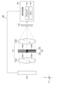
- FIG. 6 is a schematic diagram showing a subject imaged by a multispectral camera.
- FIG. 7 is a diagram showing spectral data of the background, first subject, and second subject.
- FIG. 8 is a diagram showing spectral data of the background, first subject, and second subject.
- FIG. 9 is a diagram showing a case where Expression (5), Expression (6), and Condition 1 are satisfied.
- FIG. 10 is a diagram for explaining the imaging process using a multispectral camera.
- FIG. 11 is a flow chart showing an imaging method.
- FIG. 12 is a diagram for explaining the imaging of the background in the intensity ratio measurement process.
- FIG. 13 is a diagram illustrating the intensity ratio of background luminance measured in the intensity ratio measurement step and the calculated first correction coefficient.
- FIG. 14 is a diagram for explaining the intensity ratio of background luminance measured in the intensity ratio measurement step and the calculated first correction coefficient.
- FIG. 15 is a flow chart showing an imaging method.
- FIG. 15 is a flow chart showing an imaging method.
- FIG. 16 is a diagram for explaining the intensity ratio of background luminance measured in the intensity ratio measurement step, and the calculated first correction coefficient and second correction coefficient.
- FIG. 17 is a diagram for explaining the intensity ratio of background luminance measured in the intensity ratio measurement step and the calculated first correction coefficient and second correction coefficient.
- FIG. 18 is a diagram illustrating an example of a recommended background.
- FIG. 19 is a diagram illustrating an example of a recommended background.
- FIG. 20 is a schematic diagram showing an example of a multispectral camera.
- FIG. 21 is a schematic diagram showing an example of a filter unit included in a multispectral camera.
- wavelength images have been acquired using multispectral cameras.
- a multispectral camera using polarization pixels (e.g., 0°, 45°, 90°) can obtain a wavelength image for each wavelength by assigning different wavelengths to each polarization pixel.
- interference removal is generally performed. Interference removal is a process of removing signals related to other wavelengths that interfered during imaging, and removes other wavelengths that interfere with each other based on a pre-measured mixing ratio (inverse matrix operation). By properly removing the interference, it is possible to obtain an accurate wavelength image in which the interference of signals of other wavelengths is suppressed.
- the mixing ratio is often measured before actually taking an image, such as when manufacturing a multispectral camera, and stored in the memory built into the multispectral camera for use. Therefore, there may be a case where the mixture ratio measured in advance differs from the mixture ratio when actually capturing an image. In this way, when the mixing ratio measured in advance differs from the mixing ratio when actually capturing an image, it is not possible to remove interference well, and the obtained wavelength image becomes inaccurate. (Wavelength reproducibility decreases).
- a change in the surrounding environment is one of the factors that cause the mixture ratio measured in advance to differ from the mixture ratio in the actual imaging. Specifically, when the ambient environment in which the mixture ratio is measured in advance differs from the ambient environment in which the image is actually captured, the flare changes and the mixture ratio changes. The influence of changes in the surrounding environment on the wavelength image will be described below using a specific example.
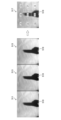
- 1 and 2 are diagrams for explaining a first example in which a wavelength image becomes inaccurate due to changes in the surrounding environment.
- Images 501, 503, and 505 are wavelength images captured by a multispectral camera of a white plate having uniform reflection characteristics.
- Image 501 is a U wavelength image of wavelength U
- image 503 is a V wavelength image of wavelength V
- image 505 is a W wavelength image of wavelength W.
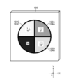
- FIG. An image 507 is a pseudo-color image obtained by replacing the wavelength U with blue (B: BLUE), the wavelength V with green (G: GREEN), and the wavelength W with red (R: RED), for example.
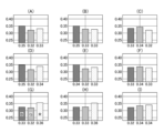
- FIG. 2 shows graphs (A) to (I) corresponding to the luminance intensity ratios of wavelength U, wavelength V, and wavelength W in regions (A) to (I) of the image 507 .
- the luminance intensity ratio in the regions (A) to (I) is uniform.
- image 501 U wavelength image
- image 503 V wavelength image
- image 505 W wavelength image
- the intensity ratios of the luminances between are also equal.
- the surrounding environment when the images 501, 503, and 505 were actually captured differs from the surrounding environment when the mixing ratio was measured.
- the image 501, the image 503, and the image 505 have different luminance intensity ratios.
- the luminance intensity ratios among the images 501, 503, and 505 are not equal (for example, in region (E), the difference in intensity ratio between the images 501, 503, and 505 is about 2%. ).
- the surrounding environment differs between when the mixing ratio is measured and when the actual image is captured, which may cause flares and the like to change, making it impossible to acquire accurate wavelength images (maintaining wavelength reproducibility).
- 3 and 4 are diagrams for explaining a second example in which the wavelength image becomes inaccurate due to changes in the surrounding environment.
- a black object 519 is imaged against a background of a white plate having uniform reflection characteristics.
- Image 511 is a U wavelength image of wavelength U
- image 513 is a V wavelength image of wavelength V
- image 515 is a W wavelength image of wavelength W.
- An image 517 is a pseudo-color image generated under the same conditions as those described with reference to FIG. FIG. 4 shows graphs (A) to (I) corresponding to the luminance intensity ratios of wavelength U, wavelength V, and wavelength W in regions (A) to (I) of the image 517 .
- the surrounding environment when the images 511, 513, and 515 were captured differs from the surrounding environment when the mixing ratio was measured.
- the image 513 and the image 515 have different luminance intensity ratios.
- the luminance intensity ratios among the images 511, 513, and 515 are not equal (for example, in region (E), the amount of difference in luminance intensity ratio between the images 511, 513, and 515 is approximately 6%).
- FIG. 5 is a flow chart showing the imaging method of the present invention. Each step of the imaging method described below is performed by processor 142 of multispectral camera 100 (FIG. 20). Also, the processor 142 executes each step by executing a dedicated program for the imaging method stored in the memory 144 .
- the processor 142 acquires spectral data of the background 2, the first subject 3, and the second subject 4.
- the processor 142 selects a plurality of wavelengths from the wavelength bands (wavelength bands) of the spectrum data of the background 2, first subject 3, and second subject 4.
- FIG. In this example, the first wavelength ⁇ (1), the second wavelength ⁇ (2), and the third wavelength ⁇ (3) are selected.
- the processor 142 uses the first wavelength ⁇ (1), the second wavelength ⁇ (2), and the third wavelength ⁇ (3) to A subject including at least one of the second subjects 4 is imaged.
- processor 142 acquires spectral data of the objects (background 2, first object 3, and second object 4).
- FIG. 6 is a schematic diagram showing subjects (first subject, second subject, and background (third subject)) captured by the multispectral camera 100.
- FIG. 6 is a schematic diagram showing subjects (first subject, second subject, and background (third subject)) captured by the multispectral camera 100.
- the subject consists of a first subject 3, a second subject 4, and a background 2.
- a multispectral camera 100 images an object including at least one of a background 2, a first object 3, and a second object 4 to identify the first object 3 and the second object 4 located on the background 2. Sensing is performed. Accordingly, processor 142 obtains spectral data regarding the reflectance of background 2 , first object 3 , and second object 4 .
- FIG. 7 and 8 are diagrams showing spectrum data of the background 2, the first subject 3, and the second subject 4.
- FIG. 7 and 8 are diagrams showing spectrum data of the background 2, the first subject 3, and the second subject 4.
- Spectral data SD1 first spectral data
- spectral data SD2 second spectral data
- spectral data SD3 third spectral data
- the wavelength ranges of spectrum data SD1, spectrum data SD2, and spectrum data SD3 acquired by processor 142 are wavelength ranges in which the wavelength range of spectrum data SD1 and the wavelength range of spectrum data SD2 overlap. That is, in the case shown in FIG.
- the wavelength range of the spectrum data SD1 and the spectrum data SD2 is from 400 nm to 1000 nm
- the spectrum data SD3 is from 400 nm to 1000 nm
- the wavelength range of the spectrum data SD1 to SD3 is from 400 nm to 1000 nm. They overlap at 1000 nm. Therefore, processor 142 acquires spectral data SD1-SD3 in the wavelength range of 400 nm-1000 nm.
- the reflectance corresponding to each wavelength of the background 2, the first subject 3, and the second subject 4 is displayed as spectral data in the same manner as in FIG. , the spectrum data SD2 corresponds to the second object 4, and the spectrum data SD3 corresponds to the background 2.
- FIG. 8 the reflectance corresponding to each wavelength of the background 2, the first subject 3, and the second subject 4 is displayed as spectral data in the same manner as in FIG. , the spectrum data SD2 corresponds to the second object 4, and the spectrum data SD3 corresponds to the background 2.
- the wavelength regions of the spectrum data SD1 and the spectrum data SD2 overlap from 550 nm to 1000 nm. Therefore, the wavelength range of 550 nm to 1000 nm is sufficient for the spectrum data SD3, and the processor 142 obtains the spectrum data SD1 to SD3 in the wavelength range of 550 nm to 1000 nm.
- the processor 142 acquires spectral data SD1-SD3 in various forms.
- the spectral data SD1 to SD3 may be acquired by imaging the background 2, the first subject 3, and the second subject 4 with a hyperspectral camera and input to the multispectral camera 100.
- the spectral data SD1-SD3 may be selected from a database in which various spectral data are stored and input to the multispectral camera 100 for acquisition by the processor 142.
- the spectral data SD1 to SD3 may be stored in advance in the memory 144 of the multispectral camera 100 and the processor 142 may acquire them.
- the processor 142 In wavelength acquisition selection, the processor 142, based on the acquired spectral data SD1, spectral data SD2, and spectral data SD3, selects a first wavelength ⁇ (1), a second wavelength ⁇ (2), and a third wavelength ⁇ (3). to select.
- the processor 142 selects a plurality of wavelengths by obtaining at least two or more factors using the difference or the ratio of the feature amounts of the two spectral data out of the spectral data SD1, the spectral data SD2, and the spectral data SD3 as factors.
- the difference in feature amount (reflectance) of spectral data is used as a factor.
- the spectrum data SD1 the spectrum data SD2, and the spectrum data SD3 described with reference to FIG. 7, at least a wavelength (reference wavelength ) and different wavelengths. Therefore, conventionally, for example, 420 nm has been selected as at least the second wavelength ⁇ (2) (reference wavelength), and 500 nm has been selected as the first wavelength ⁇ (1).
- the processor 142 calculates the reflectance difference (first factor) between the spectrum data SD3 and the spectrum data SD1 and the reflectance difference (second factor) between the spectrum data SD3 and the spectrum data SD2. Based on the relationship, a first wavelength ⁇ (1), a second wavelength ⁇ (2) and a third wavelength ⁇ (3) are selected. For example, the processor 142 selects 850 nm as the second wavelength ⁇ (2) (reference wavelength) at which the first and second factors are minimum. Note that the processor 142 may select a wavelength that minimizes at least one of the first factor and the second factor as the reference wavelength.
- the processor 142 sets the first wavelength ⁇ (1) to 925 nm, which is larger than the second wavelength ⁇ (2) and allows discrimination between the first subject 3 and the second subject 4. Select as For example, as the first wavelength ⁇ (1), a wavelength that maximizes the sum of the first factor and the second factor within a predetermined range (15% or 5%) described below may be selected. Processor 142 also selects third wavelength ⁇ (3) as 875 nm between first wavelength ⁇ (1) and second wavelength ⁇ (2).
- the processor 142 determines that the first factor (difference in reflectance between spectrum data SD3 and SD1) and the second factor (difference in reflectance between spectrum data SD3 and SD2) are within a range of 15%.
- a certain first wavelength ⁇ (1) to third wavelength ⁇ (3) can be selected.
- the processor 142 selects the first wavelength ⁇ (1) to the third wavelength ⁇ (3) that satisfy the following equations.
- ⁇ is the reflectance ⁇ 1 to ⁇ 3 of the first object 3 at the first wavelength ⁇ (1) to the third wavelength ⁇ (3) respectively, and ⁇ is the first wavelength ⁇ (1) to the third wavelength ⁇ (3).
- the reflectances ⁇ 1 to ⁇ 3 of the background 2 at the wavelength ⁇ (3) are input, and the reflectances ⁇ 1 to ⁇ 3 of the second object 4 at the first wavelength ⁇ (1) to the third wavelength ⁇ (3) are input as ⁇ . be done.
- ( ⁇ ) and ( ⁇ ) at the second wavelength are smaller than the corresponding values of the first wavelength ⁇ (1) and the third wavelength ⁇ (3), the first wavelength ⁇ (1) ⁇ third wavelength ⁇ (3) is selected (Condition 1).
- FIG. 9 is a diagram showing a case where Expression (5), Expression (6), and Condition 1 are satisfied. Note that FIG. 9 shows spectrum data SD1 to SD3 and first wavelength ⁇ (1) to third wavelength ⁇ (3).
- the difference M1, the difference N1, the difference M2 (not shown because it is 0), the difference N2 (not shown because it is 0), the difference M3, and the first wavelength ⁇ where the difference N3 is within 15% (1) to ⁇ (3) are selected. Furthermore, as the difference M2 and the difference N2, the first wavelength ⁇ (1) to the third wavelength ⁇ (3), which are smaller than the difference M1, the difference N1, the difference M3, and the difference N3, are selected.
- the processor 142 sets the first factor (difference in reflectance between spectral data SD3 and SD1) and second factor (difference in reflectance between spectral data SD3 and SD2) to 5%. can be selected from the first wavelength ⁇ (1) to the third wavelength ⁇ (3) within the range of .
- the processor 142 selects the first wavelength ⁇ (1) to the third wavelength ⁇ (3) that satisfy the following equations.
- ⁇ is the reflectance ⁇ 1 to ⁇ 3 of the first object 3 at the first wavelength ⁇ (1) to the third wavelength ⁇ (3) respectively, and ⁇ is the first wavelength ⁇ (1) to the third wavelength ⁇ (3).
- the reflectances ⁇ 1 to ⁇ 3 of the background 2 at the wavelength ⁇ (3) are input, and the reflectances ⁇ 1 to ⁇ 3 of the second object 4 at the first wavelength ⁇ (1) to the third wavelength ⁇ (3) are input as ⁇ . be done.
- ( ⁇ ) and ( ⁇ ) at the second wavelength are smaller than the corresponding values of the first wavelength ⁇ (1) and the third wavelength ⁇ (3), the first wavelength ⁇ (1) ⁇ third wavelength ⁇ (3) is selected (Condition 1).
- the processor 142 selects the first wavelength ⁇ (1) to the third wavelength ⁇ (3) by factors based on the spectrum data SD1 to SD3. Accordingly, since the difference from the reflectance of the background 2 is within a certain range, the influence of changes in the surrounding environment can be suppressed.
- the processor 142 may select the first wavelength ⁇ (1) to the third wavelength ⁇ (3) according to another mode.
- the processor 142 causes the acquired spectral data SD1 to SD3 to be displayed on the display provided on the back of the multispectral camera 100, and the user can select the first wavelength ⁇ (1) to the third wavelength ⁇ (3) from the display. ), and the processor 142 selects the first wavelength ⁇ (1) to the third wavelength ⁇ (3) based on instructions from the user input via the operation unit (not shown) of the multispectral camera 100.
- the processor 142 captures the first object 3, the second object 4, the background 2 (the third object ) is captured.
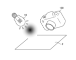
- FIG. 10 is a diagram for explaining the imaging process by the multispectral camera 100.
- FIG. FIG. 10 shows a specific example in which the background 2 is a conveyor belt, and the first subject 3 and the second subject 4 are placed on it and are continuously carried.
- the multispectral camera 100 images a first object 3 and a second object 4 that are continuously conveyed.
- the processor 142 causes the multispectral camera 100 to image the scene of the first subject 3 and the second subject 4 located on the background 2 .
- the multispectral camera 100 sometimes captures a scene with only the background 2, a scene with only the first subject 3 positioned on the background 2, and a scene with only the second subject 4 positioned on the background 2.
- the multispectral camera 100 is set so as to acquire first to third wavelength images corresponding to the first to third wavelengths ⁇ (1) to ⁇ (3) selected in the wavelength selection step.
- the illumination device 10 illuminates the background 2, the first subject 3, and the second subject 4 in accordance with the imaging by the multispectral camera 100 or all the time (illumination step).
- the illumination device 10 uses a light source a, a light source b, or a light source in which the light source a and the light source b are mixed.
- the illumination device 10 should be a shadowless illumination device. is preferred.
- the multispectral camera 100 performs interference elimination processing on the acquired first to third wavelength images as necessary.
- the multispectral camera 100 performs sensing for identifying the first subject 3 and the second subject 4 (detecting their existence, etc.) based on the captured first to third wavelength images.
- the reflectances of the first subject 3, the second subject 4, and the background 2 are Since the first wavelength ⁇ (1) to the third wavelength ⁇ (3) are selected for which the factor of is within a predetermined range, the influence of changes in the surrounding environment is suppressed, and high wavelength reproducibility is maintained. Acquisition can be performed.
- This embodiment includes an intensity ratio measurement step and a correction step (first correction step) in addition to the imaging method of the first embodiment described above.
- FIG. 11 is a flowchart showing the imaging method of this embodiment.
- the imaging method described below is performed by processor 142 of multispectral camera 100 .
- the processor 142 executes each step by executing a dedicated program for the imaging method stored in the memory 144 .
- the processor 142 acquires spectral data of the background 2, the first subject 3, and the second subject 4.
- the processor 142 selects the first wavelength ⁇ (1), the second wavelength ⁇ ( 2) Select a third wavelength ⁇ (3).
- the processor 142 images the background 2 with the first wavelength ⁇ (1), the second wavelength ⁇ (2), and the third wavelength ⁇ (3), and Wavelength images (image data) of the first wavelength ⁇ (1), the second wavelength ⁇ (2), and the third wavelength ⁇ (3) of 2 are acquired, and the first wavelength ⁇ (1) to the third wavelength ⁇ (1) are obtained in a plurality of regions.
- the intensity ratio of luminance of three wavelengths ⁇ (3) is measured.
- the processor 142 uses the first wavelength ⁇ (1), the second wavelength ⁇ (2), and the third wavelength ⁇ (3) to A subject including at least one of the second subjects 4 is imaged.
- the processor 142 corrects the intensity ratios of the multiple regions based on the first intensity ratio, which is one of the measured intensity ratios.
- the processor 142 measures the luminance intensity ratio of the background 2 using the first wavelength ⁇ (1) to the third wavelength ⁇ (3). Specifically, the processor 142 captures only the background 2 with the multispectral camera 100 at the first wavelength ⁇ (1) to the third wavelength ⁇ (3) to acquire the first to third wavelength images. .
- FIG. 12 is a diagram explaining the imaging of the background 2 in the intensity ratio measurement process.
- the background 2 is imaged by the multispectral camera 100, and a first wavelength image, a second wavelength image, and a third wavelength image of the background 2 are acquired.
- the background 2 imaged here is the same as the background 2 imaged in the imaging process.
- a white plate having uniform reflectance at the first wavelength ⁇ (1), the second wavelength ⁇ (2), and the third wavelength ⁇ (3) is used.
- background 2 uses a chart in which the intensity ratios at the first wavelength ⁇ (1), the second wavelength ⁇ (2), and the third wavelength ⁇ (3) are constant in a plurality of regions.
- the illumination device 10 is an illumination device used in the imaging process. Note that the same light source is preferably used in the intensity ratio measurement process and the imaging process.
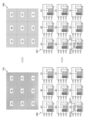
- FIG. 13 and 14 are diagrams for explaining the intensity ratio of the brightness of the background 2 measured in the intensity ratio measurement process and the calculated first correction coefficient.
- FIG. 13 shows the measurement results obtained with the light source a
- FIG. 14 shows the measurement results obtained with the light source b.
- a pseudo-color image 101 (FIG. 13) is generated based on the first to third wavelength images. Specifically, the luminance intensity ratio of the first wavelength image is red (R: RED), the luminance intensity ratio of the second wavelength image is blue (B: BLUE), and the luminance intensity ratio of the third wavelength image is green.
- a pseudo-color image 101 is generated by superimposing with (G: GREEN).
- Reference numeral 105 denotes luminance intensity at the first wavelength ⁇ (1), the second wavelength ⁇ (2), and the third wavelength ⁇ (3) in the regions (A) to (I) of the pseudo-color image 101. The ratios are shown correspondingly in graphs (A)-(I).
- the luminance intensity ratios shown in graphs (A) to (I) are averages or representative values of the luminance intensity ratios of the regions (A) to (I).
- the processor 142 performs the first correction to align the luminance intensity ratios at the first wavelength ⁇ (1), the second wavelength ⁇ (2), and the third wavelength ⁇ (3) in the regions (A) to (I). Get coefficients.
- the processor 142 converts the luminance intensity ratio (first intensity ratio) of the central area (E) of the pseudo-color image 101 to the area (A) to area (D) and area (F) to area (I).
- a first correction factor for adjusting the intensity ratio is obtained.
- the pseudo-color image 103 is obtained by applying the first correction factor to the pseudo-color image 101 .
- the pseudo-color image 103 has a uniform luminance intensity ratio, as indicated by graphs (A) to (I) indicated by reference numeral 107 . That is, the first correction coefficient makes the luminance intensity ratios of the regions (A) to (I) the same.
- a pseudo-color image 109 (FIG. 14), like the pseudo-color image 101, is generated based on the first to third wavelength images.
- Reference numeral 113 denotes the luminance intensity ratio at the first wavelength ⁇ (1), the second wavelength ⁇ (2), and the third wavelength ⁇ (3) of the regions (A) to (I) of the pseudo-color image 109. are shown in graphs (A) to (I).
- the processor 142 converts the luminance intensity ratio (first intensity ratio) of the central area (E) of the pseudo-color image 109 to the area (A) to area (D) and area (F) to area (I).
- a first correction factor for adjusting the intensity ratio is obtained.
- Applying the first correction factor to pseudo-color image 109 results in pseudo-color image 111 .
- the pseudo-color image 111 has a uniform luminance intensity ratio, as indicated by graphs (A) to (I) indicated by reference numeral 115 . That is, the luminance intensity ratio of the regions (A) to (I) becomes uniform by the first correction coefficient.
- the intensity ratio of the luminance of the first wavelength ⁇ (1) to the third wavelength ⁇ (3) of the background 2 is measured, and based on the measurement result, the first correction coefficient is calculated.
- the first correction coefficient may be obtained for each pixel of the image, or the first correction coefficient may be obtained for a larger or smaller region.
- the processor 142 applies the first correction coefficient acquired in the intensity ratio measurement step to the first wavelength image, the second wavelength image, and the third wavelength image captured in the imaging step. Then, the luminance intensity ratio of the regions (A) to (I) is corrected.
- the first correction coefficient is preferably applied to the entire first to third wavelength images. image data) may be applied with the first correction factor. The influence of changes in the surrounding environment is suppressed in the first, second, and third wavelength images corrected with the first correction coefficient. Therefore, the first to third wavelength images can be obtained while maintaining wavelength reproducibility, and accurate sensing can be performed.
- This embodiment includes a correction step (second correction step) in addition to the imaging method of the second embodiment described above.
- FIG. 15 is a flowchart showing the imaging method of this embodiment.
- the imaging method described below is performed by processor 142 of multispectral camera 100 .
- the processor 142 executes each step by executing a dedicated program for the imaging method stored in the memory 144 .
- the processor 142 acquires spectral data of the background 2, the first subject 3, and the second subject 4.
- the processor 142 selects the first wavelength ⁇ (1), the second wavelength ⁇ (2 ), and select the third wavelength ⁇ (3).
- the processor 142 images the background 2 with the first wavelength ⁇ (1), the second wavelength ⁇ (2), and the third wavelength ⁇ (3), and Wavelength images (image data) of the first wavelength ⁇ (1), the second wavelength ⁇ (2), and the third wavelength ⁇ (3) of 2 are acquired, and the intensity ratio of the luminance of multiple wavelengths in multiple regions is calculated. measure.
- the processor 142 uses the first wavelength ⁇ (1), the second wavelength ⁇ (2), and the third wavelength ⁇ (3) to A subject including at least one of the second subjects 4 is imaged.
- the processor 142 corrects the intensity ratios of the multiple regions based on the first intensity ratio, which is one of the intensity ratios measured in the intensity ratio measurement step.
- the processor 142 performs correction to reduce the difference in the intensity ratios measured in the intensity ratio measurement step.
- the second correction coefficient is calculated in addition to the first correction coefficient.
- the first correction coefficient and the second correction coefficient are calculated separately will be described, but the present invention is not limited to this.
- a correction coefficient that is a combination of the first correction coefficient and the second correction coefficient may be calculated.
- 16 and 17 are diagrams for explaining the intensity ratio of the brightness of the background 2 measured in the intensity ratio measurement process and the calculated first correction coefficient and second correction coefficient. 13 and 14 are denoted by the same reference numerals, and description thereof will be omitted.
- the second correction coefficient is a correction coefficient that reduces the difference in the luminance intensity ratio of each wavelength in the regions (A) to (I).
- the second correction coefficient is a correction coefficient that equalizes the intensity of luminance between the first wavelength ⁇ (1) to the third wavelength ⁇ (3) in the regions (A) to (I).
- the luminance intensity ratios of the regions (A) to (I) are uniform due to the first correction coefficient.
- the luminance intensity ratios of the first wavelength ⁇ (1) to the third wavelength ⁇ (3) are not uniform.
- the intensity ratios are 0.33, 0.32, and 0.35.
- this non-uniform intensity ratio is corrected to be uniform to 0.33, 0.33, and 0.33.
- the second correction coefficients are similarly calculated for other regions.
- a pseudo-color image 151 is obtained by applying the second correction factor to the pseudo-color image 103 . Areas (A) to (I) of the pseudo-color image 151 have luminance intensity ratios of 0.33, 0.32, and 0.35 as indicated by reference numeral 153 .
- the pseudo-color image 151 will show the original white color of the background 2 .
- the luminance intensity ratio of the first wavelength ⁇ (1) to the third wavelength ⁇ (3) is not uniform as shown in graphs (A) to (I) of reference numeral 115. .
- the intensity ratios are 0.34, 0.34, 0.32, but by applying the second correction factor, they are reduced to 0.33, 0. 0.33 and 0.33 are corrected.
- a pseudo-color image 155 is obtained by applying the second correction factor to the pseudo-color image 111 .
- Areas (A) to (I) of the pseudo-color image 155 have luminance intensity ratios of 0.33, 0.32, and 0.35 as indicated by reference numeral 157 . Pseudo-color image 155 will now show the original white color of background 2 .
- the intensity ratio of the luminance of the first wavelength ⁇ (1) to the third wavelength ⁇ (3) of the background 2 is measured, and based on the measurement result, the first correction coefficient and a second correction factor are calculated.
- the second correction coefficient may be obtained for each pixel of the image, or the second correction coefficient may be obtained for a larger area or a smaller area.
- the processor 142 uses the second correction coefficient acquired in the intensity ratio measurement step to convert the first wavelength image, the second wavelength image, and the third wavelength image captured in the imaging step.
- a second correction factor is applied to the image to correct the intensity ratio of area (A) to area (I).
- the second correction coefficient is preferably applied to the entire first to third wavelength images.
- image data may be applied with a second correction factor.
- the processor 142 can perform highly accurate sensing by correcting the sensitivity of the image sensor 130 (FIG. 20) based on the first correction coefficient and/or the second correction coefficient.
- ⁇ Other Embodiment 1> In the above-described embodiment, an example has been described in which three different first wavelength ⁇ (1), second wavelength ⁇ (2), and third wavelength ⁇ (3) are selected in the wavelength selection process. However, the number of wavelengths selected in the wavelength selection process is not limited to three wavelengths as long as a plurality of wavelengths are selected. For example, in the wavelength selection step, two wavelengths may be selected, or the first wavelength ⁇ (1) and the second wavelength ⁇ (2) described above may be selected.
- the processor 142 determines that the first factor (difference in reflectance between spectral data SD3 and SD1) and the second factor (difference in reflectance between spectral data SD3 and SD2) are within a range of 15%.
- the processor 142 selects a first wavelength ⁇ (1) and a second wavelength ⁇ (2) that satisfy the following equations.
- ⁇ is the reflectance ⁇ 1 and ⁇ 2 of the first object 3 at the first wavelength ⁇ (1) and the second wavelength ⁇ (2) respectively, and ⁇ is the first wavelength ⁇ (1) and the second wavelength ⁇ (2).
- the reflectances ⁇ 1 and ⁇ 2 of the background 2 at two wavelengths ⁇ (2) are input, respectively, and ⁇ is the reflectance ⁇ 1 and ⁇ 2 of the second object 4 at the first wavelength ⁇ (1) and the second wavelength ⁇ (2). each is entered.
- ( ⁇ ) and ( ⁇ ) at the second wavelength are smaller than the corresponding values of the first wavelength ⁇ (1), the first wavelength ⁇ (1) and the second wavelength ⁇ (2) is selected (condition 2).
- the processor 142 sets the first factor (difference in reflectance between spectral data SD3 and SD1) and second factor (difference in reflectance between spectral data SD3 and SD2) to 5%.
- a first wavelength ⁇ (1) and a second wavelength ⁇ (2) can be chosen that are within the range of .
- the processor 142 selects a first wavelength ⁇ (1) and a second wavelength ⁇ (2) that satisfy the following equations.
- ⁇ is the reflectance ⁇ 1 and ⁇ 2 of the first object 3 at the first wavelength ⁇ (1) and the second wavelength ⁇ (2) respectively, and ⁇ is the first wavelength ⁇ (1) and the second wavelength ⁇ (2).
- the reflectances ⁇ 1 and ⁇ 2 of the background 2 at two wavelengths ⁇ (2) are input, respectively, and ⁇ is the reflectance ⁇ 1 and ⁇ 2 of the second object 4 at the first wavelength ⁇ (1) and the second wavelength ⁇ (2). each is entered.
- ( ⁇ - ⁇ ) and ( ⁇ - ⁇ ) at the second wavelength ⁇ (2) are smaller than the corresponding values of the first wavelength ⁇ (1), the first wavelength ⁇ (1) and the second wavelength ⁇ (2) is selected (Condition 2).
- two wavelengths (first wavelength ⁇ (1) and second wavelength ⁇ (2) are selected in the wavelength selection step. is selected and imaging is performed, it is possible to acquire the number of wavelength images desired by the user.
- the background 2 was a predetermined white plate.
- the processor 142 notifies the optimum background based on the reflectance (spectral data) of the first subject 3 and the second subject 4 (notification step).
- the memory 144 of the multispectral camera 100 of the present embodiment stores the spectrum data of each of the multiple replacement subjects (multiple backgrounds) that can be replaced with the background 2 and the multiple replacement subjects. Based on the spectral data SD1 of the first subject 3 and the spectral data SD2 of the second subject 4, the processor 142 notifies one replacement subject (background) among the multiple replacement subjects as a recommended background. Note that the processor 142 can notify the replacement subject on a display unit (not shown) provided on the back surface of the multispectral camera 100 .
- the multispectral camera 100 may also include a background display device 150 that variably displays the background 2 (see FIG. 20).
- the background display device 150 is composed of, for example, a liquid crystal display or the like under the control of the processor 142, and can display a desired color as the background (third subject variable display step). In this way, by changing the background color on the background display device 150, when objects with completely different spectral reflectances are detected at the same time, the background color can be changed for each place, or the multispectral display with the same setting can be performed.
- the background color can be easily changed when it is desired to use the camera 100 for a different purpose (for example, detection of another subject).
- Figures 18 and 19 are diagrams explaining examples of recommended backgrounds.
- FIG. 18 shows recommended background spectral data SD4 (fourth spectral data). Based on the spectrum data SD1 of the first subject 3 and the spectrum data SD2 of the second subject 4, the background having the spectrum data SD4 is selected as a recommended subject and notified.
- the spectrum data SD4 has a small difference in reflectance between the spectrum data SD1 and the spectrum data SD2 in the wavelength range of 400 nm to 1000 nm. By using the background having such spectral data SD4, it is possible to select multiple wavelengths for imaging with the multispectral camera 100 in a wide wavelength range.
- FIG. 19 shows recommended background spectral data SD5.
- the background having the spectrum data SD5 is selected as a recommended subject and notified. Since the spectral data SD5 intersects the spectral data SD1 and the spectral data SD2 at a plurality of points, it has a plurality of points where the difference in reflectance from the spectral data SD1 and the spectral data SD2 is small.
- imaging can be performed at a plurality of locations (wavelength ranges).
- FIG. 20 is a schematic diagram showing an example of a multispectral camera 100 used in the imaging method of the present invention.
- FIG. 21 is a schematic diagram showing an example of the filter unit 120 included in the multispectral camera 100. As shown in FIG.
- the multispectral camera 100 shown in FIG. 20 is composed of a photographing optical system 110 including lenses 110A and 110B and a filter unit 120, an image sensor (imaging device) 130, and a signal processing section 140.
- a background display device 150 may also be connected to the multispectral camera 100 .
- the background display device 150 is connected to the signal processing section 140 and controlled by the processor 142 .
- a band-pass filter unit 124 included in the filter unit 120 (FIG. 21) has a first wavelength ⁇ (1), a second wavelength ⁇ (2), a third A first band-pass filter (first wavelength selection element) 124A, a second band-pass filter (second wavelength selection element) 124B, and a third band-pass that transmit light in a wavelength band centered at wavelength ⁇ (3). It is composed of a filter (third wavelength selection element) 124C.
- the filter unit 120 has four pupil regions (first pupil region to fourth pupil region), and the unused fourth pupil region is shielded by the shielding member B (see FIG. 21).
- the filter unit 120 is composed of a polarizing filter unit 122 and a bandpass filter unit 124 and is preferably arranged at or near the pupil position of the imaging optical system 110 .
- the polarizing filter unit 122 includes a first polarizing filter 122A, a second polarizing filter 122B, a third It consists of a polarizing filter 122C.
- the first polarizing filter 122A has a polarizing direction of 0°
- the second polarizing filter 122B has a polarizing direction of 90°
- the third polarizing filter 122C has a polarizing direction of 45°.
- the band-pass filter unit 124 includes a first band-pass filter 124A and a second band-pass filter 124B that select wavelength regions of light that passes through the first, second, and third pupil regions of the imaging optical system 110, respectively. , and a third bandpass filter 124C. Therefore, the light transmitted through the first pupil region of the imaging optical system 110 is linearly polarized by the first polarizing filter 122A, and is filtered by the first band-pass filter 124A only in the wavelength range including the first wavelength ⁇ (1). To Penetrate.
- the light passing through the second pupil region of the imaging optical system 110 is linearly polarized by the second polarizing filter 122B (linearly polarized in a direction different from that of the first polarizing filter 122A by 90°), and is further polarized by the second bandpass filter 124B. Therefore, only light in a wavelength range including the second wavelength ⁇ (2) is transmitted. Further, the light passing through the third pupil region of the imaging optical system 110 is linearly polarized by the third polarizing filter 122C, and only the light in the wavelength region including the third wavelength ⁇ (3) is filtered by the third bandpass filter 124C. To Penetrate.
- the image sensor 130 includes a plurality of pixels composed of photoelectric conversion elements arranged two-dimensionally, and a first polarizing filter, a second polarizing filter, and a third polarizing filter having polarization directions of 0°, 45°, and 90°. It is arranged and configured regularly.
- the first polarizing filter 122A and the first polarizing filter of the image sensor 130 have the same polarizing direction
- the second polarizing filter 122B and the second polarizing filter of the image sensor 130 have the same polarizing direction
- the third polarizing filter has the same polarization direction
- the polarizing filter 122C and the third polarizing filter of the image sensor 130 have the same polarization direction.
- the signal processing unit 140 reads pixel signals from the pixels of the image sensor 130 in which the first polarizing filters are arranged, thereby obtaining a first wavelength image of a narrow band wavelength-selected by the first band-pass filter 124A.
- a second wavelength image of a narrow band wavelength-selected by the second band-pass filter 124B is acquired, and the third polarizing filter of the image sensor 130 is obtained.
- a third wavelength image of a narrow band wavelength-selected by the third band-pass filter 124C is obtained.
- the first wavelength image, the second wavelength image, and the third wavelength image acquired by the signal processing unit 140 are images suitable for separating the first subject 3 and the second subject 4 .
- a composite image with enhanced dynamic range and enhanced sensing performance can be created.
- interference elimination processing of the first wavelength image, the second wavelength image, and the third wavelength image is performed as necessary.
- the hardware structure of the processing unit that executes various processes is the following various processors.
- the circuit configuration can be changed after manufacturing, such as CPU (Central Processing Unit), FPGA (Field Programmable Gate Array), which is a general-purpose processor that executes software (program) and functions as various processing units.
- Programmable Logic Device PLD
- ASIC Application Specific Integrated Circuit
- One processing unit may be composed of one of these various processors, or composed of two or more processors of the same type or different types (for example, a plurality of FPGAs, or a combination of a CPU and an FPGA).
- a plurality of processing units may be configured by one processor.
- a processor functions as multiple processing units.
- SoC System On Chip
- SoC System On Chip
- the hardware structure of these various processors is, more specifically, an electrical circuit that combines circuit elements such as semiconductor elements.
- Second Subject 10 Illumination Device 100: Multispectral Camera 110: Shooting Optical System 110A: Lens 110B: Lens 120: Filter Unit 122: Polarizing Filter Unit 122A: First Polarizing Filter 122B: Second polarizing filter 122C: Third polarizing filter 124: Bandpass filter unit 124A: First bandpass filter 124B: Second bandpass filter 124C: Third bandpass filter 130: Image sensor 140: Signal processing unit 142: Processor 144 : Memory 150 : Background display device
Landscapes
- Engineering & Computer Science (AREA)
- Multimedia (AREA)
- Signal Processing (AREA)
- Physics & Mathematics (AREA)
- Spectroscopy & Molecular Physics (AREA)
- General Physics & Mathematics (AREA)
- Investigating Or Analysing Materials By Optical Means (AREA)
- Color Television Image Signal Generators (AREA)
Abstract
Provided are an image-capturing method and program which can obtain a wavelength image with high wave reproducibility maintained. The image-capturing method captures subjects with a multi-spectrum camera that includes a processor, wherein the processor executes: a data acquisition step (step S10) for acquiring first spectrum data of a first subject, second spectrum data of a second subject, and third spectrum data of a third subject; a wavelength selection step (step S11) for selecting a plurality of wavelengths from wavelength bands of the acquired first to third spectrum data; and an image-capturing step (step S12) for selecting a plurality of wavelengths by obtaining at least two calculation amounts that are determined, in the wavelength selection step (step S11), as the difference or ratio between feature amounts of two pieces among the first spectrum data, the second spectrum data, or the third spectrum data, and capturing subjects including at least one among the first subject, the second subject, or the third subject in the plurality of wavelengths.
Description
本発明は、撮像方法及びプログラムに関し、特にマルチスペクトルカメラの撮像方法及びプログラムに関する。
The present invention relates to an imaging method and program, and more particularly to an imaging method and program for a multispectral camera.
従来より、マルチスペクトルカメラを利用して異なる波長毎の画像を取得し,その画像を様々な用途に応用することが行われている。
Conventionally, multispectral cameras have been used to acquire images for different wavelengths, and the images have been applied to various purposes.
例えば特許文献1では、予め測定されたカメラの分光感度特性を用いて被写体の色推定を行う技術が記載されている。
For example, Patent Literature 1 describes a technique for estimating the color of a subject using pre-measured spectral sensitivity characteristics of a camera.
本開示の技術に係る一つの実施形態は、高い波長再現性を維持した波長画像を得ることができる撮像方法及びプログラムを提供する。
One embodiment according to the technology of the present disclosure provides an imaging method and program capable of obtaining a wavelength image maintaining high wavelength reproducibility.
本発明の一の態様である撮像方法は、プロセッサを備えるマルチスペクトルカメラにより、被写体を撮像する撮像方法であって、プロセッサは、第1被写体の第1スペクトルデータと、第2被写体の第2スペクトルデータと、第3被写体の第3スペクトルデータと、を取得するデータ取得工程と、取得した第1から第3スペクトルデータの波長域から複数の波長を選定する波長選定工程と、波長選定工程では、第1スペクトルデータ、第2スペクトルデータ、第3スペクトルデータのうち、2つのスペクトルデータの特徴量の差又は比を因子とし、少なくとも2つ以上の前記因子をもとに複数の波長を選定し、複数の波長で第1被写体、第2被写体、第3被写体の少なくとも1つを含む被写体を撮像する撮像工程と、を行う。
An imaging method according to one aspect of the present invention is an imaging method for imaging a subject with a multispectral camera including a processor, wherein the processor captures first spectral data of a first subject and a second spectrum of a second subject. In the data acquisition step of acquiring the data and the third spectral data of the third subject, the wavelength selection step of selecting a plurality of wavelengths from the wavelength range of the acquired first to third spectral data, and the wavelength selection step, A plurality of wavelengths are selected based on at least two or more of the factors, with the difference or ratio of the feature amount of two spectral data among the first spectral data, the second spectral data, and the third spectral data as factors, an imaging step of imaging a subject including at least one of a first subject, a second subject, and a third subject at a plurality of wavelengths.
好ましくは、第1から第3スペクトルデータの波長域は、少なくとも第1スペクトルデータの波長域と第2スペクトルデータの波長域が重なる波長域である。
Preferably, the wavelength regions of the first to third spectral data are wavelength regions in which at least the wavelength regions of the first spectral data and the wavelength regions of the second spectral data overlap.
好ましくは、因子は、第1スペクトルデータと第3スペクトルデータの特徴量の差又は比である第1因子と、第2スペクトルデータと第3スペクトルデータの特徴量の差又は比である第2因子を含み、第1因子と第2因子とに基づいて複数の波長を選定する。
Preferably, the factors are a first factor that is a difference or ratio of feature amounts between the first spectral data and the third spectral data, and a second factor that is a difference or ratio of feature amounts between the second spectral data and the third spectral data. and selecting a plurality of wavelengths based on a first factor and a second factor.
好ましくは、複数の波長の1つは、第1因子及び第2因子の少なくとも一方が最小となる波長である。
Preferably, one of the plurality of wavelengths is the wavelength at which at least one of the first factor and the second factor is minimized.
好ましくは、波長選定工程で選定した複数の波長により、第3被写体の画像データの複数の領域内で複数の波長の輝度の強度比を計測する工程と、強度比に基づいて少なくとも第3被写体の画像データを補正する補正工程と、を更に有する。
Preferably, using the plurality of wavelengths selected in the wavelength selection step, a step of measuring intensity ratios of brightnesses of the plurality of wavelengths within a plurality of regions of the image data of the third subject; and a correction step of correcting the image data.
好ましくは、補正工程は、計測した強度比の1つである第1強度比に基づいて複数の領域の強度比を補正する第1補正工程を含む。
Preferably, the correcting step includes a first correcting step of correcting the intensity ratios of the plurality of regions based on a first intensity ratio that is one of the measured intensity ratios.
好ましくは、補正工程は、計測した強度比の差を小さくする補正をする第2補正工程を含む。
Preferably, the correcting step includes a second correcting step of correcting to reduce the difference between the measured intensity ratios.
好ましくは、補正工程は、計測した強度比の1つである第1強度比に基づいて複数の領域の強度比を補正する第1補正工程と、計測した強度比の差を小さくする補正をする第2補正工程を含む。
Preferably, the correcting step includes a first correcting step of correcting the intensity ratios of the plurality of regions based on a first intensity ratio that is one of the measured intensity ratios, and a correction to reduce the difference between the measured intensity ratios. A second correction step is included.
好ましくは、第3被写体は、複数の領域で波長選定工程で選定した複数の波長の輝度の強度比が一定である。
Preferably, the third subject has a constant luminance intensity ratio of the plurality of wavelengths selected in the wavelength selection step in the plurality of regions.
好ましくは、波長選定工程で第1波長と第2波長を選定し、第1波長及び第2波長における第1被写体の反射率αと第3被写体の反射率βが以下の式(1)の関係を満たし、第1波長及び第2波長における第2被写体の反射率γと第3被写体の反射率βが以下の式(2)の関係を満たし、第2波長における(β-α)及び(β-γ)は第1波長における(β-α)及び(β-γ)よりも小さい。
|β-α|÷(β+α)≦0.15・・・(1)
|β-γ|÷(β+γ)≦0.15・・・(2) Preferably, the first wavelength and the second wavelength are selected in the wavelength selection step, and the reflectance α of the first subject and the reflectance β of the third subject at the first wavelength and the second wavelength are related by the following formula (1): , the reflectance γ of the second object and the reflectance β of the third object at the first and second wavelengths satisfy the relationship of the following formula (2), and (β-α) and (β −γ) is less than (β−α) and (β−γ) at the first wavelength.
|β−α|÷(β+α)≦0.15 (1)
|β−γ|÷(β+γ)≦0.15 (2)
好ましくは、波長選定工程で第1波長と第2波長を選定し、第1波長及び第2波長における第1被写体の反射率αと第3被写体の反射率βが以下の式(3)の関係を満たし、第1波長及び第2波長における第2被写体の反射率γと第3被写体の反射率βが以下の式(4)の関係を満たし、第2波長における(β-α)及び(β-γ)は第1波長における(β-α)及び(β-γ)よりも小さい。
|β-α|÷(β+α)≦0.05・・・(3)
|β-γ|÷(β+γ)≦0.05・・・(4) Preferably, the first wavelength and the second wavelength are selected in the wavelength selection step, and the reflectance α of the first subject and the reflectance β of the third subject at the first wavelength and the second wavelength satisfy the relationship of the following formula (3): , the reflectance γ of the second object and the reflectance β of the third object at the first and second wavelengths satisfy the relationship of the following formula (4), and (β-α) and (β −γ) is less than (β−α) and (β−γ) at the first wavelength.
|β−α|÷(β+α)≦0.05 (3)
|β−γ|÷(β+γ)≦0.05 (4)
好ましくは、波長選定工程で第1波長と第2波長と第3波長とを選定し、第1波長、第2波長、及び第3波長における第1被写体の反射率αと第3被写体の反射率βが以下の式(5)の関係を満たし、第1波長、第2波長、及び第3波長における第2被写体の反射率γと第3被写体の反射率βが以下の式(6)の関係を満たし、第2波長における(β-α)及び(β-γ)は、第1波長及び第3波長における(β-α)及び(β-γ)よりも小さい。
|β-α|÷(β+α)≦0.15・・・(5)
|β-γ|÷(β+γ)≦0.15・・・(6) Preferably, the first wavelength, the second wavelength, and the third wavelength are selected in the wavelength selection step, and the reflectance α of the first subject and the reflectance of the third subject at the first wavelength, the second wavelength, and the third wavelength are determined. β satisfies the relationship of the following equation (5), and the reflectance γ of the second subject and the reflectance β of the third subject at the first, second and third wavelengths satisfy the relationship of the following equation (6) and (β-α) and (β-γ) at the second wavelength are smaller than (β-α) and (β-γ) at the first and third wavelengths.
|β−α|÷(β+α)≦0.15 (5)
|β−γ|÷(β+γ)≦0.15 (6)
好ましくは、波長選定工程で第1波長と第2波長と第3波長とを選定し、第1波長、第2波長、及び第3波長における第1被写体の反射率αと第3被写体の反射率βが以下の式(7)の関係を満たし、第1波長、第2波長、及び第3波長における第2被写体の反射率γと第3被写体の反射率βが以下の式(8)の関係を満たし、第2波長における(β-α)及び(β-γ)は、第1波長及び第3波長における(β-α)及び(β-γ)よりも小さい。
|β-α|÷(β+α)≦0.05・・・(7)
|β-γ|÷(β+γ)≦0.05・・・(8) Preferably, the first wavelength, the second wavelength, and the third wavelength are selected in the wavelength selection step, and the reflectance α of the first subject and the reflectance of the third subject at the first wavelength, the second wavelength, and the third wavelength are determined. β satisfies the relationship of the following equation (7), and the reflectance γ of the second subject and the reflectance β of the third subject at the first, second and third wavelengths satisfy the relationship of the following equation (8) and (β-α) and (β-γ) at the second wavelength are smaller than (β-α) and (β-γ) at the first and third wavelengths.
|β−α|÷(β+α)≦0.05 (7)
|β−γ|÷(β+γ)≦0.05 (8)
好ましくは、第3被写体と置換可能な複数置換被写体と複数置換被写体の各々の第4スペクトルデータを記憶するメモリを備え、プロセッサは、第1スペクトルデータ、第2スペクトルデータ、及び第4スペクトルデータに基づいて、複数置換被写体のうちの一つの置換被写体を推奨する第3被写体として報知する報知工程を行う。
Preferably, a memory is provided for storing fourth spectral data of each of the multiple-replacement subject replaceable with the third subject and the multiple-replacement subject, and the processor stores the first spectral data, the second spectral data, and the fourth spectral data. Based on this, a notification step of notifying one of the plurality of replacement subjects as the recommended third subject is performed.
好ましくは、プロセッサは、補正工程に基づいて、マルチスペクトルカメラの撮像素子の感度を補正する感度補正工程を行う。
Preferably, the processor performs a sensitivity correction step of correcting the sensitivity of the imaging device of the multispectral camera based on the correction step.
好ましくは、第3被写体を可変に表示する第3被写体可変表示工程を更に行う。
Preferably, the step of variably displaying the third subject is further performed.
好ましくは、無影化の照明の照射工程を更に行う。
Preferably, a shadowless lighting irradiation step is further performed.
本発明の他の態様であるプログラムは、プロセッサを備えるマルチスペクトルカメラにより、被写体を撮像する撮像方法を実行させるプログラムであって、プロセッサに、第1被写体の第1スペクトルデータと、第2被写体の第2スペクトルデータと、第3被写体の第3スペクトルデータと、を取得するデータ取得工程と、取得した第1から第3スペクトルデータの波長域から複数の波長を選定する波長選定工程と、波長選定工程では、第1スペクトルデータ、第2スペクトルデータ、第3スペクトルデータのうち、2つのスペクトルデータの特徴量の差又は比を因子とし、少なくとも2つ以上の前記因子をもとに複数の波長を選定し、複数の波長で第1被写体、第2被写体、第3被写体の少なくとも1つを含む被写体を撮像する撮像工程と、を行わせる。
A program that is another aspect of the present invention is a program that causes a multispectral camera including a processor to execute an imaging method for imaging a subject, wherein the processor is provided with first spectral data of a first subject and a data acquisition step of acquiring second spectral data and third spectral data of a third subject; a wavelength selection step of selecting a plurality of wavelengths from the wavelength range of the acquired first to third spectral data; In the step, the difference or ratio of the feature amount of two spectral data out of the first spectral data, the second spectral data, and the third spectral data is used as a factor, and a plurality of wavelengths are determined based on at least two of the factors. an imaging step of selecting and imaging an object including at least one of a first object, a second object, and a third object at a plurality of wavelengths.
以下、添付図面にしたがって本発明に係る撮像方法及びプログラムの好ましい実施の形態について説明する。
Preferred embodiments of the imaging method and program according to the present invention will be described below with reference to the accompanying drawings.
先ず、以下で波長画像が不正確(波長再現性が低下)となってしまうことに関して説明する。
First, the following will explain how the wavelength image becomes inaccurate (wavelength reproducibility is reduced).
従来より、マルチスペクトルカメラによって、波長毎に対応した画像(波長画像)を取得することが行われている。例えば、偏光画素(例えば0°、45°、90°)を利用したマルチスペクトルカメラ(図20参照)は、各偏光画素にそれぞれ異なる波長を割り当てることにより、波長毎に波長画像を得ることができる。ここで、波長画像を生成する工程では、一般に混信除去が行われる。混信除去とは、撮像時に混信した他の波長に関する信号を除去する処理であり、予め計測された混合比率を元に混信した他の波長を除去する(逆行列演算)ことである。そして、この混信除去が適切に行われることにより、他の波長の信号の混信が抑制された正確な波長画像を得ることができる。
Conventionally, images corresponding to each wavelength (wavelength images) have been acquired using multispectral cameras. For example, a multispectral camera (see FIG. 20) using polarization pixels (e.g., 0°, 45°, 90°) can obtain a wavelength image for each wavelength by assigning different wavelengths to each polarization pixel. . Here, in the step of generating the wavelength image, interference removal is generally performed. Interference removal is a process of removing signals related to other wavelengths that interfered during imaging, and removes other wavelengths that interfere with each other based on a pre-measured mixing ratio (inverse matrix operation). By properly removing the interference, it is possible to obtain an accurate wavelength image in which the interference of signals of other wavelengths is suppressed.
一般に混合比率は、マルチスペクトルカメラの製造時など、実際に撮像を行う前に計測され、マルチスペクトルカメラに内蔵されるメモリなどに記憶されて利用されることが多い。したがって、予め計測された混合比率と、実際に撮像を行う場合の混合比率とが異なる場合が発生する。このように、予め計測された混合比率と実際に撮像を行った場合の混合比率とが異なる場合には、混信除去を上手く行うことができず、得られる波長画像が不正確となってしまうことがある(波長再現性が低下する)。予め計測された混合比率と実際に撮像を行う場合の混合比率とが異なってしまう要因の1つとして、周辺環境の変化が挙げられる。具体的には、予め混合比率を計測する際の周辺環境と実際に撮像を行う際の周辺環境とが異なることにより、フレアが変化し混合比率が変化してしまう。以下に、周辺環境の変化よる波長画像への影響に関して具体例を用いて説明する。
In general, the mixing ratio is often measured before actually taking an image, such as when manufacturing a multispectral camera, and stored in the memory built into the multispectral camera for use. Therefore, there may be a case where the mixture ratio measured in advance differs from the mixture ratio when actually capturing an image. In this way, when the mixing ratio measured in advance differs from the mixing ratio when actually capturing an image, it is not possible to remove interference well, and the obtained wavelength image becomes inaccurate. (Wavelength reproducibility decreases). A change in the surrounding environment is one of the factors that cause the mixture ratio measured in advance to differ from the mixture ratio in the actual imaging. Specifically, when the ambient environment in which the mixture ratio is measured in advance differs from the ambient environment in which the image is actually captured, the flare changes and the mixture ratio changes. The influence of changes in the surrounding environment on the wavelength image will be described below using a specific example.
図1及び図2は、周辺環境の変化により波長画像が不正確となってしまう第1例を説明する図である。
1 and 2 are diagrams for explaining a first example in which a wavelength image becomes inaccurate due to changes in the surrounding environment.
画像501、画像503、及び画像505は、マルチスペクトルカメラにより均一な反射特性を有する白色板を撮像した各波長画像である。画像501は波長UのU波長画像であり、画像503は波長VのV波長画像であり、画像505は波長WのW波長画像である。また画像507は、例えば波長Uを青色(B:BLUE)、波長Vを緑色(G:GREEN)、及び波長Wを赤色(R:RED)に置き換えた場合の疑似カラー画像である。図2には、画像507の領域(A)~(I)の波長U、波長V、及び波長Wの輝度の強度比が対応するグラフ(A)~(I)で示されている。
Images 501, 503, and 505 are wavelength images captured by a multispectral camera of a white plate having uniform reflection characteristics. Image 501 is a U wavelength image of wavelength U, image 503 is a V wavelength image of wavelength V, and image 505 is a W wavelength image of wavelength W. FIG. An image 507 is a pseudo-color image obtained by replacing the wavelength U with blue (B: BLUE), the wavelength V with green (G: GREEN), and the wavelength W with red (R: RED), for example. FIG. 2 shows graphs (A) to (I) corresponding to the luminance intensity ratios of wavelength U, wavelength V, and wavelength W in regions (A) to (I) of the image 507 .
本来ならばマルチスペクトルカメラ100により、均一な反射特性を有する白色板を撮像した場合には、領域(A)~(I)における輝度の強度比は均一となる。また、本来ならばマルチスペクトルカメラ100により、均一な反射特性を有する白色板を撮像した場合には、画像501(U波長画像)、画像503(V波長画像)、及び画像505(W波長画像)間の輝度の強度比も等しくなる。しかしながら、実際に画像501、画像503、及び画像505を撮像した際の周辺環境と混合比率を計測した際の周辺環境とは異なることにより、図示するように、領域(A)~(I)では、画像501、画像503、及び画像505の各々が示す輝度の強度比が異なる。また画像501、画像503、及び画像505間の輝度の強度比も等しくない(例えば、領域(E)では、画像501、画像503、及び画像505間の強度比のズレ量は約2%である)。
Originally, when a white plate having uniform reflection characteristics is imaged by the multispectral camera 100, the luminance intensity ratio in the regions (A) to (I) is uniform. In addition, originally, when a white plate having uniform reflection characteristics is imaged by the multispectral camera 100, image 501 (U wavelength image), image 503 (V wavelength image), and image 505 (W wavelength image) The intensity ratios of the luminances between are also equal. However, the surrounding environment when the images 501, 503, and 505 were actually captured differs from the surrounding environment when the mixing ratio was measured. , the image 501, the image 503, and the image 505 have different luminance intensity ratios. Also, the luminance intensity ratios among the images 501, 503, and 505 are not equal (for example, in region (E), the difference in intensity ratio between the images 501, 503, and 505 is about 2%. ).
このように、混合比率を計測した時と実際の撮像時とにおいて周辺環境が異なることからフレア等が変化し、正確な(波長再現性を維持した)波長画像の取得ができない場合がある。
In this way, the surrounding environment differs between when the mixing ratio is measured and when the actual image is captured, which may cause flares and the like to change, making it impossible to acquire accurate wavelength images (maintaining wavelength reproducibility).
図3及び図4は、周辺環境の変化により波長画像が不正確となってしまう第2例を説明する図である。本例では、均一な反射特性を有する白色板を背景として黒色被写体519が撮像されている。
3 and 4 are diagrams for explaining a second example in which the wavelength image becomes inaccurate due to changes in the surrounding environment. In this example, a black object 519 is imaged against a background of a white plate having uniform reflection characteristics.
画像511は波長UのU波長画像であり、画像513は波長VのV波長画像であり、画像515は波長WのW波長画像である。また、画像517は、図1で説明した場合と同様の条件で生成された疑似カラー画像である。図4には、画像517の領域(A)~(I)の波長U、波長V、及び波長Wの輝度の強度比が対応するグラフ(A)~(I)で示されている。
Image 511 is a U wavelength image of wavelength U, image 513 is a V wavelength image of wavelength V, and image 515 is a W wavelength image of wavelength W. An image 517 is a pseudo-color image generated under the same conditions as those described with reference to FIG. FIG. 4 shows graphs (A) to (I) corresponding to the luminance intensity ratios of wavelength U, wavelength V, and wavelength W in regions (A) to (I) of the image 517 .
画像511、画像513、及び画像515を撮像した際の周辺環境と混合比率を計測した際の周辺環境とは異なることにより、図示するように、領域(A)~(I)では、画像511、画像513、及び画像515の各々が示す輝度の強度比が異なる。また画像511、画像513、及び画像515間の輝度の強度比も等しくなってない(例えば、領域(E)では、画像511、画像513、及び画像515間の輝度の強度比のズレ量は約6%である)。
The surrounding environment when the images 511, 513, and 515 were captured differs from the surrounding environment when the mixing ratio was measured. The image 513 and the image 515 have different luminance intensity ratios. In addition, the luminance intensity ratios among the images 511, 513, and 515 are not equal (for example, in region (E), the amount of difference in luminance intensity ratio between the images 511, 513, and 515 is approximately 6%).
このように、混合比率を取得した時と実際の撮像時とにおいて周辺環境が異なることからフレア等が変化することにより、正確な(波長再現性が維持された)波長画像の取得ができない場合がある。また、黒色被写体519のような、背景と被写体との反射率の差が大きい場合には、より波長間の輝度の強度比のズレ量が大きくなってしまい、波長再現性が低下してしまう。
In this way, when the mixing ratio is acquired and when the actual image is captured, the surrounding environment is different, and flare and the like change. be. In addition, when the difference in reflectance between the background and the subject is large, such as the black subject 519, the amount of deviation in the luminance intensity ratio between wavelengths increases, and wavelength reproducibility deteriorates.
上述した例のように、混合比率が変わっているにもかかわらず単に混信除去を行うだけでは、不正確な波長画像が取得されてしまう。
As in the example above, an inaccurate wavelength image will be acquired simply by removing interference despite the fact that the mixing ratio has changed.
そこで、以下に開示する実施形態では、フレア等が変化することを抑制したり、撮像の初期において発生しているフレア等に合わせて波長画像に対して補正を行うことにより、周辺環境が変化していても、正確な波長画像を得ることができる(波長再現性を維持することができる)。
Therefore, in the embodiments disclosed below, changes in the surrounding environment are suppressed by suppressing changes in flare and the like, and correcting wavelength images in accordance with flare and the like occurring in the early stages of imaging. Accurate wavelength images can be obtained (wavelength reproducibility can be maintained).
<第1実施形態>
図5は、本発明の撮像方法を示すフローチャートである。以下で説明する撮像方法の各工程は、マルチスペクトルカメラ100(図20)のプロセッサ142によって実施される。また、プロセッサ142はメモリ144に記憶されている撮像方法の専用プログラムを実行することにより各工程を実施する。 <First embodiment>
FIG. 5 is a flow chart showing the imaging method of the present invention. Each step of the imaging method described below is performed byprocessor 142 of multispectral camera 100 (FIG. 20). Also, the processor 142 executes each step by executing a dedicated program for the imaging method stored in the memory 144 .
図5は、本発明の撮像方法を示すフローチャートである。以下で説明する撮像方法の各工程は、マルチスペクトルカメラ100(図20)のプロセッサ142によって実施される。また、プロセッサ142はメモリ144に記憶されている撮像方法の専用プログラムを実行することにより各工程を実施する。 <First embodiment>
FIG. 5 is a flow chart showing the imaging method of the present invention. Each step of the imaging method described below is performed by
データ取得工程(ステップS10)では、プロセッサ142は、背景2、第1被写体3、及び第2被写体4のスペクトルデータを取得する。次に、波長選定工程(ステップS11)では、プロセッサ142は、背景2、第1被写体3、及び第2被写体4のスペクトルデータの波長域(波長帯域)から複数の波長を選定する。本例では、第1波長λ(1)、第2波長λ(2)、第3波長λ(3)が選定される。次に、撮像工程(ステップS12)では、プロセッサ142は、第1波長λ(1)、第2波長λ(2)、及び第3波長λ(3)により、背景2、第1被写体3、及び第2被写体4のうち少なくとも1つを含む被写体を撮像する。
In the data acquisition step (step S10), the processor 142 acquires spectral data of the background 2, the first subject 3, and the second subject 4. Next, in the wavelength selection step (step S11), the processor 142 selects a plurality of wavelengths from the wavelength bands (wavelength bands) of the spectrum data of the background 2, first subject 3, and second subject 4. FIG. In this example, the first wavelength λ(1), the second wavelength λ(2), and the third wavelength λ(3) are selected. Next, in the imaging step (step S12), the processor 142 uses the first wavelength λ(1), the second wavelength λ(2), and the third wavelength λ(3) to A subject including at least one of the second subjects 4 is imaged.
以下に各工程に関して詳細に説明を行う。
Below is a detailed explanation of each process.
[データ取得工程]
データ取得工程ではプロセッサ142は、被写体(背景2、第1被写体3、及び第2被写体4)のスペクトルデータを取得する。 [Data acquisition process]
In the data acquisition step,processor 142 acquires spectral data of the objects (background 2, first object 3, and second object 4).
データ取得工程ではプロセッサ142は、被写体(背景2、第1被写体3、及び第2被写体4)のスペクトルデータを取得する。 [Data acquisition process]
In the data acquisition step,
図6は、マルチスペクトルカメラ100により撮像される被写体(第1被写体、第2被写体、及び背景(第3被写体))を示す概略図である。
FIG. 6 is a schematic diagram showing subjects (first subject, second subject, and background (third subject)) captured by the multispectral camera 100. FIG.
被写体は、第1被写体3、第2被写体4、及び背景2で構成される。マルチスペクトルカメラ100により、背景2、第1被写体3、及び第2被写体4のうち少なくとも1つを含む被写体を撮像して、背景2上に位置する第1被写体3及び第2被写体4を識別するセンシングが行われる。したがって、プロセッサ142は、背景2、第1被写体3、及び第2被写体4の反射率に関するスペクトルデータを取得する。
The subject consists of a first subject 3, a second subject 4, and a background 2. A multispectral camera 100 images an object including at least one of a background 2, a first object 3, and a second object 4 to identify the first object 3 and the second object 4 located on the background 2. Sensing is performed. Accordingly, processor 142 obtains spectral data regarding the reflectance of background 2 , first object 3 , and second object 4 .
図7及び図8は、背景2、第1被写体3、及び第2被写体4のスペクトルデータを示す図である。
7 and 8 are diagrams showing spectrum data of the background 2, the first subject 3, and the second subject 4. FIG.
図7では、背景2、第1被写体3、及び第2被写体4の各波長に対応する反射率がスペクトルデータとして表示されている。スペクトルデータSD1(第1スペクトルデータ)は第1被写体3に対応し、スペクトルデータSD2(第2スペクトルデータ)は第2被写体4に対応し、スペクトルデータSD3(第3スペクトルデータ)は背景2に対応する。プロセッサ142が取得するスペクトルデータSD1、スペクトルデータSD2、及びスペクトルデータSD3の波長域は、スペクトルデータSD1の波長域とスペクトルデータSD2の波長域とが重なる波長域である。つまり図7に示す場合では、スペクトルデータSD1とスペクトルデータSD2との波長域は400nm~1000nmであり、スペクトルデータSD3は400nm~1000nmの波長域であり、スペクトルデータSD1~SD3の波長域は400nm~1000nmで重なっている。したがって、プロセッサ142は、スペクトルデータSD1~SD3を波長域400nm~1000nmで取得する。
In FIG. 7, the reflectance corresponding to each wavelength of the background 2, the first subject 3, and the second subject 4 is displayed as spectral data. Spectral data SD1 (first spectral data) corresponds to the first subject 3, spectral data SD2 (second spectral data) corresponds to the second subject 4, and spectral data SD3 (third spectral data) corresponds to the background 2. do. The wavelength ranges of spectrum data SD1, spectrum data SD2, and spectrum data SD3 acquired by processor 142 are wavelength ranges in which the wavelength range of spectrum data SD1 and the wavelength range of spectrum data SD2 overlap. That is, in the case shown in FIG. 7, the wavelength range of the spectrum data SD1 and the spectrum data SD2 is from 400 nm to 1000 nm, the spectrum data SD3 is from 400 nm to 1000 nm, and the wavelength range of the spectrum data SD1 to SD3 is from 400 nm to 1000 nm. They overlap at 1000 nm. Therefore, processor 142 acquires spectral data SD1-SD3 in the wavelength range of 400 nm-1000 nm.
図8では、図7と同様に背景2、第1被写体3、及び第2被写体4の各波長に対応する反射率がスペクトルデータとして表示されており、スペクトルデータSD1は第1被写体3に対応し、スペクトルデータSD2は第2被写体4に対応し、スペクトルデータSD3は背景2に対応する。
In FIG. 8, the reflectance corresponding to each wavelength of the background 2, the first subject 3, and the second subject 4 is displayed as spectral data in the same manner as in FIG. , the spectrum data SD2 corresponds to the second object 4, and the spectrum data SD3 corresponds to the background 2. FIG.
図8に示す場合では、スペクトルデータSD1とスペクトルデータSD2との波長域は550nm~1000nmで重なっている。したがって、スペクトルデータSD3の波長域も550nm~1000nmの範囲で十分であり、プロセッサ142は550nm~1000nmの波長域のスペクトルデータSD1~SD3を取得する。
In the case shown in FIG. 8, the wavelength regions of the spectrum data SD1 and the spectrum data SD2 overlap from 550 nm to 1000 nm. Therefore, the wavelength range of 550 nm to 1000 nm is sufficient for the spectrum data SD3, and the processor 142 obtains the spectrum data SD1 to SD3 in the wavelength range of 550 nm to 1000 nm.
プロセッサ142は、様々な形態によりスペクトルデータSD1~SD3を取得する。例えば、スペクトルデータSD1~SD3は、ハイパースペクトルカメラにより背景2、第1被写体3、及び第2被写体4が撮像されて取得され、マルチスペクトルカメラ100に入力されてもよい。また、スペクトルデータSD1~SD3は、様々なスペクトルデータが保存されているデータベースから選択されて、マルチスペクトルカメラ100に入力されプロセッサ142が取得してもよい。また、スペクトルデータSD1~SD3は、予めマルチスペクトルカメラ100のメモリ144に記憶されていて、それをプロセッサ142は取得してもよい。
The processor 142 acquires spectral data SD1-SD3 in various forms. For example, the spectral data SD1 to SD3 may be acquired by imaging the background 2, the first subject 3, and the second subject 4 with a hyperspectral camera and input to the multispectral camera 100. FIG. Alternatively, the spectral data SD1-SD3 may be selected from a database in which various spectral data are stored and input to the multispectral camera 100 for acquisition by the processor 142. FIG. Also, the spectral data SD1 to SD3 may be stored in advance in the memory 144 of the multispectral camera 100 and the processor 142 may acquire them.
[波長選定工程]
波長取得選定ではプロセッサ142は、取得したスペクトルデータSD1、スペクトルデータSD2、及びスペクトルデータSD3に基づいて、第1波長λ(1)、第2波長λ(2)、及び第3波長λ(3)を選定する。プロセッサ142は、スペクトルデータSD1、スペクトルデータSD2、及びスペクトルデータSD3のうち、2つのスペクトルデータの特徴量の差又は比を因子とし、因子を少なくとも2つ以上求めて複数の波長を選定する。以下の説明では、スペクトルデータの特徴量(反射率)の差が因子とされた場合に関して説明する。 [Wavelength selection process]
In wavelength acquisition selection, theprocessor 142, based on the acquired spectral data SD1, spectral data SD2, and spectral data SD3, selects a first wavelength λ(1), a second wavelength λ(2), and a third wavelength λ(3). to select. The processor 142 selects a plurality of wavelengths by obtaining at least two or more factors using the difference or the ratio of the feature amounts of the two spectral data out of the spectral data SD1, the spectral data SD2, and the spectral data SD3 as factors. In the following description, a case will be described in which the difference in feature amount (reflectance) of spectral data is used as a factor.
波長取得選定ではプロセッサ142は、取得したスペクトルデータSD1、スペクトルデータSD2、及びスペクトルデータSD3に基づいて、第1波長λ(1)、第2波長λ(2)、及び第3波長λ(3)を選定する。プロセッサ142は、スペクトルデータSD1、スペクトルデータSD2、及びスペクトルデータSD3のうち、2つのスペクトルデータの特徴量の差又は比を因子とし、因子を少なくとも2つ以上求めて複数の波長を選定する。以下の説明では、スペクトルデータの特徴量(反射率)の差が因子とされた場合に関して説明する。 [Wavelength selection process]
In wavelength acquisition selection, the
従来技術において、図7で説明したスペクトルデータSD1、スペクトルデータSD2、及びスペクトルデータSD3では、少なくとも第1被写体3のスペクトルデータSD1と第2被写体4のスペクトルデータSD2とで差が小さい波長(基準波長)と差がある波長とを使用することが一般的である。したがって、従来では例えば、少なくとも第2波長λ(2)(基準波長)として420nmが選定され、第1波長λ(1)として500nmが選定されてきた。
In the prior art, in the spectrum data SD1, the spectrum data SD2, and the spectrum data SD3 described with reference to FIG. 7, at least a wavelength (reference wavelength ) and different wavelengths. Therefore, conventionally, for example, 420 nm has been selected as at least the second wavelength λ(2) (reference wavelength), and 500 nm has been selected as the first wavelength λ(1).
しかしながら、本実施形態では、プロセッサ142は、スペクトルデータSD3とスペクトルデータSD1との反射率の差(第1因子)、及びスペクトルデータSD3とスペクトルデータSD2との反射率の差(第2因子)の関係に基づいて、第1波長λ(1)、第2波長λ(2)、及び第3波長λ(3)が選定される。例えばプロセッサ142は、第2波長λ(2)(基準波長)として、第1因子及び第2因子が最小である850nmを選定する。なお、プロセッサ142は、基準波長として第1因子及び第2因子の少なくとも一方が最小となる波長を選定してもよい。またプロセッサ142は、第1因子及び第2因子が第2波長λ(2)の場合よりも大きく、第1被写体3と第2被写体4との識別が可能な925nmを第1波長λ(1)として選定する。例えば第1波長λ(1)は、以下で説明する所定の範囲(15%又は5%)内において、第1因子と第2因子との和が最大となる波長が選定されてもよい。またプロセッサ142は、第3波長λ(3)を、第1波長λ(1)と第2波長λ(2)との間の875nmと選定する。
However, in this embodiment, the processor 142 calculates the reflectance difference (first factor) between the spectrum data SD3 and the spectrum data SD1 and the reflectance difference (second factor) between the spectrum data SD3 and the spectrum data SD2. Based on the relationship, a first wavelength λ(1), a second wavelength λ(2) and a third wavelength λ(3) are selected. For example, the processor 142 selects 850 nm as the second wavelength λ(2) (reference wavelength) at which the first and second factors are minimum. Note that the processor 142 may select a wavelength that minimizes at least one of the first factor and the second factor as the reference wavelength. Further, the processor 142 sets the first wavelength λ(1) to 925 nm, which is larger than the second wavelength λ(2) and allows discrimination between the first subject 3 and the second subject 4. Select as For example, as the first wavelength λ(1), a wavelength that maximizes the sum of the first factor and the second factor within a predetermined range (15% or 5%) described below may be selected. Processor 142 also selects third wavelength λ(3) as 875 nm between first wavelength λ(1) and second wavelength λ(2).
また、プロセッサ142は、第1因子(スペクトルデータSD3とスペクトルデータSD1との反射率の差)及び第2因子(スペクトルデータSD3とスペクトルデータSD2との反射率の差)が15%の範囲内である第1波長λ(1)~第3波長λ(3)を選定することができる。
Further, the processor 142 determines that the first factor (difference in reflectance between spectrum data SD3 and SD1) and the second factor (difference in reflectance between spectrum data SD3 and SD2) are within a range of 15%. A certain first wavelength λ(1) to third wavelength λ(3) can be selected.
具体的には、プロセッサ142は、以下の式を満たすような第1波長λ(1)~第3波長λ(3)を選定する。
|β-α|÷(β+α)≦0.15・・・(5)
|β-γ|÷(β+γ)≦0.15・・・(6) Specifically, theprocessor 142 selects the first wavelength λ(1) to the third wavelength λ(3) that satisfy the following equations.
|β−α|÷(β+α)≦0.15 (5)
|β−γ|÷(β+γ)≦0.15 (6)
|β-α|÷(β+α)≦0.15・・・(5)
|β-γ|÷(β+γ)≦0.15・・・(6) Specifically, the
|β−α|÷(β+α)≦0.15 (5)
|β−γ|÷(β+γ)≦0.15 (6)
なお上式では、αは第1波長λ(1)~第3波長λ(3)における第1被写体3の反射率α1~α3が各々入力され、βは第1波長λ(1)~第3波長λ(3)における背景2の反射率β1~β3が各々入力され、γは第1波長λ(1)~第3波長λ(3)における第2被写体4の反射率γ1~γ3が各々入力される。また、この場合第2波長における(β-α)及び(β-γ)は、第1波長λ(1)及び第3波長λ(3)の対応する値よりも小さい第1波長λ(1)~第3波長λ(3)が選定される(条件1)。
In the above formula, α is the reflectance α1 to α3 of the first object 3 at the first wavelength λ(1) to the third wavelength λ(3) respectively, and β is the first wavelength λ(1) to the third wavelength λ(3). The reflectances β1 to β3 of the background 2 at the wavelength λ(3) are input, and the reflectances γ1 to γ3 of the second object 4 at the first wavelength λ(1) to the third wavelength λ(3) are input as γ. be done. Also, in this case, (β−α) and (β−γ) at the second wavelength are smaller than the corresponding values of the first wavelength λ(1) and the third wavelength λ(3), the first wavelength λ(1) ~ third wavelength λ(3) is selected (Condition 1).
図9は、式(5)、式(6)、及び条件1を満たす場合を示した図である。なお、図9には、スペクトルデータSD1~SD3、及び第1波長λ(1)~第3波長λ(3)が示されている。
FIG. 9 is a diagram showing a case where Expression (5), Expression (6), and Condition 1 are satisfied. Note that FIG. 9 shows spectrum data SD1 to SD3 and first wavelength λ(1) to third wavelength λ(3).
図9に示すように、差分M1、差分N1、差分M2(0であるため不図示)、差分N2(0であるため不図示)、差分M3、差分N3が15%以内である第1波長λ(1)~λ(3)が選定されている。更に、差分M2及び差分N2は、差分M1、差分N1、差分M3、及び差分N3よりも小さい、第1波長λ(1)~第3波長λ(3)が選定されている。
As shown in FIG. 9, the difference M1, the difference N1, the difference M2 (not shown because it is 0), the difference N2 (not shown because it is 0), the difference M3, and the first wavelength λ where the difference N3 is within 15% (1) to λ(3) are selected. Furthermore, as the difference M2 and the difference N2, the first wavelength λ(1) to the third wavelength λ(3), which are smaller than the difference M1, the difference N1, the difference M3, and the difference N3, are selected.
また、更に好ましくは、プロセッサ142は、第1因子(スペクトルデータSD3とスペクトルデータSD1との反射率の差)及び第2因子(スペクトルデータSD3とスペクトルデータSD2との反射率の差)が5%の範囲内である第1波長λ(1)~第3波長λ(3)を選定することができる。
More preferably, the processor 142 sets the first factor (difference in reflectance between spectral data SD3 and SD1) and second factor (difference in reflectance between spectral data SD3 and SD2) to 5%. can be selected from the first wavelength λ(1) to the third wavelength λ(3) within the range of .
具体的には、プロセッサ142は、以下の式を満たすような第1波長λ(1)~第3波長λ(3)を選定する。
|β-α|÷(β+α)≦0.05・・・(7)
|β-γ|÷(β+γ)≦0.05・・・(8) Specifically, theprocessor 142 selects the first wavelength λ(1) to the third wavelength λ(3) that satisfy the following equations.
|β−α|÷(β+α)≦0.05 (7)
|β−γ|÷(β+γ)≦0.05 (8)
|β-α|÷(β+α)≦0.05・・・(7)
|β-γ|÷(β+γ)≦0.05・・・(8) Specifically, the
|β−α|÷(β+α)≦0.05 (7)
|β−γ|÷(β+γ)≦0.05 (8)
なお上式では、αは第1波長λ(1)~第3波長λ(3)における第1被写体3の反射率α1~α3が各々入力され、βは第1波長λ(1)~第3波長λ(3)における背景2の反射率β1~β3が各々入力され、γは第1波長λ(1)~第3波長λ(3)における第2被写体4の反射率γ1~γ3が各々入力される。また、この場合第2波長における(β-α)及び(β-γ)は、第1波長λ(1)及び第3波長λ(3)の対応する値よりも小さい第1波長λ(1)~第3波長λ(3)が選定される(条件1)。
In the above formula, α is the reflectance α1 to α3 of the first object 3 at the first wavelength λ(1) to the third wavelength λ(3) respectively, and β is the first wavelength λ(1) to the third wavelength λ(3). The reflectances β1 to β3 of the background 2 at the wavelength λ(3) are input, and the reflectances γ1 to γ3 of the second object 4 at the first wavelength λ(1) to the third wavelength λ(3) are input as γ. be done. Also, in this case, (β−α) and (β−γ) at the second wavelength are smaller than the corresponding values of the first wavelength λ(1) and the third wavelength λ(3), the first wavelength λ(1) ~ third wavelength λ(3) is selected (Condition 1).
以上で説明したように、プロセッサ142は、スペクトルデータSD1~スペクトルデータSD3に基づく因子によって、第1波長λ(1)~第3波長λ(3)を選定する。これにより、背景2の反射率との違いが一定の範囲内であるので、周辺環境の変化の影響を抑制することができる。
As described above, the processor 142 selects the first wavelength λ(1) to the third wavelength λ(3) by factors based on the spectrum data SD1 to SD3. Accordingly, since the difference from the reflectance of the background 2 is within a certain range, the influence of changes in the surrounding environment can be suppressed.
なお、上述した説明では、プロセッサ142が取得したスペクトルデータSD1~スペクトルデータSD3から第1波長λ(1)~第3波長λ(3)を自動で選定する場合について説明した。波長選定工程では、他の形態によりプロセッサ142が第1波長λ(1)~第3波長λ(3)を選定してもよい。例えば、プロセッサ142は、取得したスペクトルデータSD1~スペクトルデータSD3をマルチスペクトルカメラ100の背面に設けられる表示部に表示させ、ユーザがその表示から第1波長λ(1)~第3波長λ(3)を選択し、マルチスペクトルカメラ100の操作部(不図示)を介して入力されたユーザからの指示に基づいて、プロセッサ142は第1波長λ(1)~第3波長λ(3)を選定してもよい。
In the above description, the case of automatically selecting the first wavelength λ(1) to the third wavelength λ(3) from the spectrum data SD1 to SD3 acquired by the processor 142 has been described. In the wavelength selection process, the processor 142 may select the first wavelength λ(1) to the third wavelength λ(3) according to another mode. For example, the processor 142 causes the acquired spectral data SD1 to SD3 to be displayed on the display provided on the back of the multispectral camera 100, and the user can select the first wavelength λ(1) to the third wavelength λ(3) from the display. ), and the processor 142 selects the first wavelength λ(1) to the third wavelength λ(3) based on instructions from the user input via the operation unit (not shown) of the multispectral camera 100. You may
[撮像工程]
撮像工程では、プロセッサ142は、第1波長λ(1)、第2波長λ(2)、及び第3波長λ(3)で、第1被写体3、第2被写体4、背景2(第3被写体)の少なくとも1つを含む被写体を撮像する。 [Imaging process]
In the imaging process, theprocessor 142 captures the first object 3, the second object 4, the background 2 (the third object ) is captured.
撮像工程では、プロセッサ142は、第1波長λ(1)、第2波長λ(2)、及び第3波長λ(3)で、第1被写体3、第2被写体4、背景2(第3被写体)の少なくとも1つを含む被写体を撮像する。 [Imaging process]
In the imaging process, the
図10は、マルチスペクトルカメラ100による撮像工程を説明する図である。図10では、背景2がベルトコンベアであり、その上に第1被写体3及び第2被写体4が乗せられて、連続的に運ばれてくる具体例が示されている。マルチスペクトルカメラ100は、連続的に運ばれてくる第1被写体3及び第2被写体4を撮像する。
FIG. 10 is a diagram for explaining the imaging process by the multispectral camera 100. FIG. FIG. 10 shows a specific example in which the background 2 is a conveyor belt, and the first subject 3 and the second subject 4 are placed on it and are continuously carried. The multispectral camera 100 images a first object 3 and a second object 4 that are continuously conveyed.
プロセッサ142は、マルチスペクトルカメラ100に、背景2上に位置する第1被写体3及び第2被写体4のシーンの撮像を行わせる。マルチスペクトルカメラ100は、場合によっては背景2だけのシーン、背景2上に第1被写体3のみが位置しているシーン、背景2上に第2被写体4のみが位置しているシーンの撮像を行う。なお、マルチスペクトルカメラ100は、波長選定工程で選定された第1波長λ(1)~第3波長λ(3)に対応する第1波長画像~第3波長画像が取得できるように設定されている。照明装置10は、マルチスペクトルカメラ100の撮像に合わせて又は常時、背景2、第1被写体3、及び第2被写体4を照らす(照射工程)。なお、照明装置10は、光源a、光源b、又は光源a及び光源bを混合した光源が使用される。また、第1被写体3及び第2被写体4の影は、正確な第1波長画像~第3波長画像の取得に良い影響を及ぼさないので、照明装置10は、無影化の照明装置であることが好ましい。マルチスペクトルカメラ100は、必要に応じて、取得した第1波長画像~第3波長画像に対して混信除去の処理を行う。
The processor 142 causes the multispectral camera 100 to image the scene of the first subject 3 and the second subject 4 located on the background 2 . The multispectral camera 100 sometimes captures a scene with only the background 2, a scene with only the first subject 3 positioned on the background 2, and a scene with only the second subject 4 positioned on the background 2. . The multispectral camera 100 is set so as to acquire first to third wavelength images corresponding to the first to third wavelengths λ(1) to λ(3) selected in the wavelength selection step. there is The illumination device 10 illuminates the background 2, the first subject 3, and the second subject 4 in accordance with the imaging by the multispectral camera 100 or all the time (illumination step). The illumination device 10 uses a light source a, a light source b, or a light source in which the light source a and the light source b are mixed. In addition, since the shadows of the first subject 3 and the second subject 4 do not have a good effect on the accurate acquisition of the first to third wavelength images, the illumination device 10 should be a shadowless illumination device. is preferred. The multispectral camera 100 performs interference elimination processing on the acquired first to third wavelength images as necessary.
マルチスペクトルカメラ100は、撮像した第1波長画像~第3波長画像に基づいて、第1被写体3及び第2被写体4を識別する(存在の有無などを検出する)センシングを行う。
The multispectral camera 100 performs sensing for identifying the first subject 3 and the second subject 4 (detecting their existence, etc.) based on the captured first to third wavelength images.
以上で説明したように、本実施形態の撮像方法によれば、フレア等が撮像を行う周辺環境により変化した場合であっても、第1被写体3、第2被写体4、及び背景2の反射率の因子が所定の範囲内である第1波長λ(1)~第3波長(3)が選定されているので、周辺環境の変化の影響を抑制し高い波長再現性が維持された波長画像の取得を行うことができる。
As described above, according to the imaging method of the present embodiment, the reflectances of the first subject 3, the second subject 4, and the background 2 are Since the first wavelength λ(1) to the third wavelength λ(3) are selected for which the factor of is within a predetermined range, the influence of changes in the surrounding environment is suppressed, and high wavelength reproducibility is maintained. Acquisition can be performed.
<第2実施形態>
次に、本発明の第2実施形態に関して説明する。本実施形態では、上述した第1実施形態の撮像方法に加えて、強度比計測工程及び補正工程(第1補正工程)を含む。 <Second embodiment>
Next, a second embodiment of the invention will be described. This embodiment includes an intensity ratio measurement step and a correction step (first correction step) in addition to the imaging method of the first embodiment described above.
図11は、本実施形態の撮像方法を示すフローチャートである。以下で説明する撮像方法は、マルチスペクトルカメラ100のプロセッサ142によって実施される。また、プロセッサ142はメモリ144に記憶されている撮像方法の専用プログラムを実行することにより各工程を実施する。
FIG. 11 is a flowchart showing the imaging method of this embodiment. The imaging method described below is performed by processor 142 of multispectral camera 100 . Also, the processor 142 executes each step by executing a dedicated program for the imaging method stored in the memory 144 .
データ取得工程(ステップS20)では、プロセッサ142は、背景2、第1被写体3、及び第2被写体4のスペクトルデータを取得する。次に、波長選定工程(ステップS21)では、プロセッサ142は、背景2、第1被写体3、及び第2被写体4のスペクトルデータの波長域から、第1波長λ(1)、第2波長λ(2)、第3波長λ(3)を選定する。次に、強度比計測工程(ステップS22)では、プロセッサ142は、第1波長λ(1)、第2波長λ(2)、及び第3波長λ(3)により背景2を撮像して、背景2の第1波長λ(1)、第2波長λ(2)、及び第3波長λ(3)の波長画像(画像データ)を取得し複数の領域内で第1波長λ(1)~第3波長λ(3)の輝度の強度比を計測する。次に、撮像工程(ステップS23)では、プロセッサ142は、第1波長λ(1)、第2波長λ(2)、及び第3波長λ(3)により、背景2、第1被写体3、及び第2被写体4のうち少なくとも1つを含む被写体を撮像する。その後、第1補正工程(ステップS24)では、プロセッサ142は、計測した強度比の1つである第1強度比に基づいて複数の領域の強度比を補正する。
In the data acquisition step (step S20), the processor 142 acquires spectral data of the background 2, the first subject 3, and the second subject 4. Next, in the wavelength selection step (step S21), the processor 142 selects the first wavelength λ(1), the second wavelength λ( 2) Select a third wavelength λ(3). Next, in the intensity ratio measurement step (step S22), the processor 142 images the background 2 with the first wavelength λ(1), the second wavelength λ(2), and the third wavelength λ(3), and Wavelength images (image data) of the first wavelength λ (1), the second wavelength λ (2), and the third wavelength λ (3) of 2 are acquired, and the first wavelength λ (1) to the third wavelength λ (1) are obtained in a plurality of regions. The intensity ratio of luminance of three wavelengths λ(3) is measured. Next, in the imaging step (step S23), the processor 142 uses the first wavelength λ(1), the second wavelength λ(2), and the third wavelength λ(3) to A subject including at least one of the second subjects 4 is imaged. Thereafter, in the first correction step (step S24), the processor 142 corrects the intensity ratios of the multiple regions based on the first intensity ratio, which is one of the measured intensity ratios.
次に、本実施形態の特徴的部分である強度比計測工程及び第1補正工程に関して説明する。なお、本実施形態におけるその他の工程(データ取得工程、波長選定工程、及び撮像工程)は第1実施形態と同様であるので、説明は省略する。
Next, the intensity ratio measurement process and the first correction process, which are characteristic parts of this embodiment, will be described. Note that the other steps (data acquisition step, wavelength selection step, and imaging step) in this embodiment are the same as those in the first embodiment, so descriptions thereof will be omitted.
[強度比計測工程]
強度比計測工程では、プロセッサ142は、第1波長λ(1)~第3波長λ(3)により、背景2の輝度の強度比を計測する。具体的には、プロセッサ142は、第1波長λ(1)~第3波長λ(3)でマルチスペクトルカメラ100により、背景2のみを撮像し、第1波長画像~第3波長画像を取得する。 [Intensity ratio measurement process]
In the intensity ratio measurement step, theprocessor 142 measures the luminance intensity ratio of the background 2 using the first wavelength λ(1) to the third wavelength λ(3). Specifically, the processor 142 captures only the background 2 with the multispectral camera 100 at the first wavelength λ(1) to the third wavelength λ(3) to acquire the first to third wavelength images. .
強度比計測工程では、プロセッサ142は、第1波長λ(1)~第3波長λ(3)により、背景2の輝度の強度比を計測する。具体的には、プロセッサ142は、第1波長λ(1)~第3波長λ(3)でマルチスペクトルカメラ100により、背景2のみを撮像し、第1波長画像~第3波長画像を取得する。 [Intensity ratio measurement process]
In the intensity ratio measurement step, the
図12は、強度比計測工程における背景2の撮像に関して説明する図である。
FIG. 12 is a diagram explaining the imaging of the background 2 in the intensity ratio measurement process.
強度比計測工程では、マルチスペクトルカメラ100により背景2が撮像され、背景2の第1波長画像、第2波長画像、及び第3波長画像が取得される。なお、ここで撮像される背景2は、撮像工程で撮像される背景2と同一である。背景2には、例えば第1波長λ(1)、第2波長λ(2)、及び第3波長λ(3)での反射率が均一の白色板が使用される。また、例えば背景2には、第1波長λ(1)、第2波長λ(2)、及び第3波長λ(3)での強度比が複数の領域で一定であるチャートが使用される。また、照明装置10は、撮像工程で使用される照明装置である。なお、強度比計測工程と撮像工程とでは同一の光源が使用されることが好ましい。
In the intensity ratio measurement process, the background 2 is imaged by the multispectral camera 100, and a first wavelength image, a second wavelength image, and a third wavelength image of the background 2 are acquired. The background 2 imaged here is the same as the background 2 imaged in the imaging process. For the background 2, for example, a white plate having uniform reflectance at the first wavelength λ(1), the second wavelength λ(2), and the third wavelength λ(3) is used. Further, for example, background 2 uses a chart in which the intensity ratios at the first wavelength λ(1), the second wavelength λ(2), and the third wavelength λ(3) are constant in a plurality of regions. Moreover, the illumination device 10 is an illumination device used in the imaging process. Note that the same light source is preferably used in the intensity ratio measurement process and the imaging process.
図13及び図14は、強度比計測工程で計測された背景2の輝度の強度比及び算出される第1補正係数に関して説明する図である。図13は光源aで計測され、図14は光源bで計測された計測結果が示されている。
13 and 14 are diagrams for explaining the intensity ratio of the brightness of the background 2 measured in the intensity ratio measurement process and the calculated first correction coefficient. FIG. 13 shows the measurement results obtained with the light source a, and FIG. 14 shows the measurement results obtained with the light source b.
疑似カラー画像101(図13)は、第1波長画像~第3波長画像に基づいて生成される。具体的には、第1波長画像の輝度の強度比を赤(R:RED)、第2波長画像の輝度の強度比を青(B:BLUE)、第3波長画像の輝度の強度比を緑(G:GREEN)で重ね合わせることで疑似カラー画像101が生成される。また、符号105では、疑似カラー画像101の領域(A)~領域(I)の第1波長λ(1)、第2波長λ(2)、及び第3波長λ(3)での輝度の強度比がグラフ(A)~グラフ(I)で対応して示されている。なお、グラフ(A)~グラフ(I)で示される輝度の強度比は、領域(A)~領域(I)の各領域の輝度の強度比の平均又は代表値が示されている。
A pseudo-color image 101 (FIG. 13) is generated based on the first to third wavelength images. Specifically, the luminance intensity ratio of the first wavelength image is red (R: RED), the luminance intensity ratio of the second wavelength image is blue (B: BLUE), and the luminance intensity ratio of the third wavelength image is green. A pseudo-color image 101 is generated by superimposing with (G: GREEN). Reference numeral 105 denotes luminance intensity at the first wavelength λ(1), the second wavelength λ(2), and the third wavelength λ(3) in the regions (A) to (I) of the pseudo-color image 101. The ratios are shown correspondingly in graphs (A)-(I). The luminance intensity ratios shown in graphs (A) to (I) are averages or representative values of the luminance intensity ratios of the regions (A) to (I).
疑似カラー画像101及び符号105で示されるグラフ(A)~グラフ(I)で示すように、第1波長画像~第3波長画像では周辺環境の変化の影響により各波長の輝度の強度比にばらつきが発生している。したがって、プロセッサ142は、領域(A)~領域(I)において、第1波長λ(1)、第2波長λ(2)、第3波長λ(3)における輝度の強度比を揃える第1補正係数を取得する。例えば、プロセッサ142は、疑似カラー画像101の中央の領域(E)の輝度の強度比(第1強度比)に、領域(A)~領域(D)、領域(F)~領域(I)の強度比を合わせる第1補正係数を取得する。疑似カラー画像103は、第1補正係数を疑似カラー画像101に適用することにより疑似カラー画像103を得る。疑似カラー画像103は、符号107に示すグラフ(A)~グラフ(I)で示すように、均一の輝度の強度比となっている。すなわち、第1補正係数により、領域(A)~領域(I)の輝度の強度比が同じになる。
As shown in the graphs (A) to (I) indicated by the pseudo-color image 101 and reference numeral 105, in the first to third wavelength images, the luminance intensity ratio of each wavelength varies due to the influence of changes in the surrounding environment. is occurring. Therefore, the processor 142 performs the first correction to align the luminance intensity ratios at the first wavelength λ(1), the second wavelength λ(2), and the third wavelength λ(3) in the regions (A) to (I). Get coefficients. For example, the processor 142 converts the luminance intensity ratio (first intensity ratio) of the central area (E) of the pseudo-color image 101 to the area (A) to area (D) and area (F) to area (I). A first correction factor for adjusting the intensity ratio is obtained. The pseudo-color image 103 is obtained by applying the first correction factor to the pseudo-color image 101 . The pseudo-color image 103 has a uniform luminance intensity ratio, as indicated by graphs (A) to (I) indicated by reference numeral 107 . That is, the first correction coefficient makes the luminance intensity ratios of the regions (A) to (I) the same.
疑似カラー画像109(図14)、疑似カラー画像101と同様に第1波長画像~第3波長画像に基づいて生成される。また符号113では、疑似カラー画像109の領域(A)~領域(I)の第1波長λ(1)、第2波長λ(2)、及び第3波長λ(3)での輝度の強度比がグラフ(A)~グラフ(I)で示されている。
A pseudo-color image 109 (FIG. 14), like the pseudo-color image 101, is generated based on the first to third wavelength images. Reference numeral 113 denotes the luminance intensity ratio at the first wavelength λ(1), the second wavelength λ(2), and the third wavelength λ(3) of the regions (A) to (I) of the pseudo-color image 109. are shown in graphs (A) to (I).
疑似カラー画像109及び符号113で示されるグラフ(A)~グラフ(I)で示すように、第1波長画像~第3波長画像では周辺環境の変化の影響により各波長の輝度の強度比にばらつきが発生している。したがって、プロセッサ142は、疑似カラー画像109の中央の領域(E)の輝度の強度比(第1強度比)に、領域(A)~領域(D)、領域(F)~領域(I)の強度比を合わせる第1補正係数を取得する。第1補正係数を疑似カラー画像109に適用すると疑似カラー画像111を得る。疑似カラー画像111は、符号115に示すグラフ(A)~グラフ(I)で示すように、均一の輝度の強度比となっている。すなわち、第1補正係数により、領域(A)~領域(I)の輝度の強度比が均一となる。
As shown in graphs (A) to (I) indicated by the pseudo-color image 109 and reference numeral 113, the luminance intensity ratio of each wavelength varies in the first to third wavelength images due to the influence of changes in the surrounding environment. is occurring. Therefore, the processor 142 converts the luminance intensity ratio (first intensity ratio) of the central area (E) of the pseudo-color image 109 to the area (A) to area (D) and area (F) to area (I). A first correction factor for adjusting the intensity ratio is obtained. Applying the first correction factor to pseudo-color image 109 results in pseudo-color image 111 . The pseudo-color image 111 has a uniform luminance intensity ratio, as indicated by graphs (A) to (I) indicated by reference numeral 115 . That is, the luminance intensity ratio of the regions (A) to (I) becomes uniform by the first correction coefficient.
以上で説明したように、強度比計測工程では、背景2の第1波長λ(1)~第3波長λ(3)の輝度の強度比が計測され、その計測結果に基づいて第1補正係数が算出される。なお、上述した説明では画像を3×3の9領域に分けてその領域毎に第1補正係数が取得される例について説明が、本実施形態はこれに限定されるものではない。例えば、画像の画素毎に第1補正係数が取得されても良いし、より大きな領域又は小さな領域において第1補正係数が取得されてもよい。
As described above, in the intensity ratio measurement step, the intensity ratio of the luminance of the first wavelength λ(1) to the third wavelength λ(3) of the background 2 is measured, and based on the measurement result, the first correction coefficient is calculated. In the above description, an example is described in which the image is divided into 3×3=9 regions and the first correction coefficient is acquired for each region, but the present embodiment is not limited to this. For example, the first correction coefficient may be obtained for each pixel of the image, or the first correction coefficient may be obtained for a larger or smaller region.
[補正工程]
補正工程(第1補正工程)では、プロセッサ142は、撮像工程で撮像された第1波長画像、第2波長画像、及び第3波長画像に、強度比計測工程で取得した第1補正係数を適用し領域(A)~領域(I)の輝度の強度比を補正する。なお、第1補正係数は、第1波長画像~第3波長画像の全体に適用することが好ましいが、例えば、第1波長画像~第3波長画像の背景2が写っている箇所(背景2の画像データ)に、第1補正係数を適用してもよい。第1補正係数で補正が行われた第1波長画像、第2波長画像、及び第3波長画像は周辺環境の変化の影響が抑制されている。したがって、波長再現性を維持した第1波長画像~第3波長画像を得ることができ、正確なセンシングを行うことができる。 [Correction process]
In the correction step (first correction step), theprocessor 142 applies the first correction coefficient acquired in the intensity ratio measurement step to the first wavelength image, the second wavelength image, and the third wavelength image captured in the imaging step. Then, the luminance intensity ratio of the regions (A) to (I) is corrected. The first correction coefficient is preferably applied to the entire first to third wavelength images. image data) may be applied with the first correction factor. The influence of changes in the surrounding environment is suppressed in the first, second, and third wavelength images corrected with the first correction coefficient. Therefore, the first to third wavelength images can be obtained while maintaining wavelength reproducibility, and accurate sensing can be performed.
補正工程(第1補正工程)では、プロセッサ142は、撮像工程で撮像された第1波長画像、第2波長画像、及び第3波長画像に、強度比計測工程で取得した第1補正係数を適用し領域(A)~領域(I)の輝度の強度比を補正する。なお、第1補正係数は、第1波長画像~第3波長画像の全体に適用することが好ましいが、例えば、第1波長画像~第3波長画像の背景2が写っている箇所(背景2の画像データ)に、第1補正係数を適用してもよい。第1補正係数で補正が行われた第1波長画像、第2波長画像、及び第3波長画像は周辺環境の変化の影響が抑制されている。したがって、波長再現性を維持した第1波長画像~第3波長画像を得ることができ、正確なセンシングを行うことができる。 [Correction process]
In the correction step (first correction step), the
<第3実施形態>
次に、本発明の第3実施形態に関して説明する。本実施形態では、上述した第2実施形態の撮像方法に加えて、補正工程(第2補正工程)を含む。 <Third Embodiment>
Next, a third embodiment of the present invention will be described. This embodiment includes a correction step (second correction step) in addition to the imaging method of the second embodiment described above.
次に、本発明の第3実施形態に関して説明する。本実施形態では、上述した第2実施形態の撮像方法に加えて、補正工程(第2補正工程)を含む。 <Third Embodiment>
Next, a third embodiment of the present invention will be described. This embodiment includes a correction step (second correction step) in addition to the imaging method of the second embodiment described above.
図15は、本実施形態の撮像方法を示すフローチャートである。以下で説明する撮像方法は、マルチスペクトルカメラ100のプロセッサ142によって実施される。また、プロセッサ142はメモリ144に記憶されている撮像方法の専用プログラムを実行することにより各工程を実施する。
FIG. 15 is a flowchart showing the imaging method of this embodiment. The imaging method described below is performed by processor 142 of multispectral camera 100 . Also, the processor 142 executes each step by executing a dedicated program for the imaging method stored in the memory 144 .
データ取得工程(ステップS30)では、プロセッサ142は、背景2、第1被写体3、及び第2被写体4のスペクトルデータを取得する。次に、波長選定工程(ステップS31)では、プロセッサ142は、背景2、第1被写体3、及び第2被写体4のスペクトルデータの波長域から第1波長λ(1)、第2波長λ(2)、第3波長λ(3)を選定する。次に、強度比計測工程(ステップS32)では、プロセッサ142は、第1波長λ(1)、第2波長λ(2)、及び第3波長λ(3)により背景2を撮像して、背景2の第1波長λ(1)、第2波長λ(2)、及び第3波長λ(3)の波長画像(画像データ)を取得し複数の領域内で複数の波長の輝度の強度比を計測する。次に、撮像工程(ステップS33)では、プロセッサ142は、第1波長λ(1)、第2波長λ(2)、及び第3波長λ(3)により、背景2、第1被写体3、及び第2被写体4のうち少なくとも1つを含む被写体を撮像する。次に、第1補正工程(ステップS34)では、プロセッサ142は、強度比計測工程で計測した強度比の1つである第1強度比に基づいて複数の領域の強度比を補正する。次に、第2補正工程(ステップS35)では、プロセッサ142は、強度比計測工程で計測した強度比の差を小さくする補正を行う。
In the data acquisition step (step S30), the processor 142 acquires spectral data of the background 2, the first subject 3, and the second subject 4. Next, in the wavelength selection step (step S31), the processor 142 selects the first wavelength λ(1), the second wavelength λ(2 ), and select the third wavelength λ(3). Next, in the intensity ratio measurement step (step S32), the processor 142 images the background 2 with the first wavelength λ(1), the second wavelength λ(2), and the third wavelength λ(3), and Wavelength images (image data) of the first wavelength λ (1), the second wavelength λ (2), and the third wavelength λ (3) of 2 are acquired, and the intensity ratio of the luminance of multiple wavelengths in multiple regions is calculated. measure. Next, in the imaging step (step S33), the processor 142 uses the first wavelength λ(1), the second wavelength λ(2), and the third wavelength λ(3) to A subject including at least one of the second subjects 4 is imaged. Next, in the first correction step (step S34), the processor 142 corrects the intensity ratios of the multiple regions based on the first intensity ratio, which is one of the intensity ratios measured in the intensity ratio measurement step. Next, in the second correction step (step S35), the processor 142 performs correction to reduce the difference in the intensity ratios measured in the intensity ratio measurement step.
次に、本実施形態の特徴的部分である強度比計測工程及び第2補正工程に関して説明する。なお、データ取得工程、波長選定工程、撮像工程、第1補正工程は第1実施形態及び第2実施形態と同様であるので、ここでは説明を省略する。
Next, the intensity ratio measurement process and the second correction process, which are characteristic parts of this embodiment, will be described. Note that the data acquisition process, wavelength selection process, imaging process, and first correction process are the same as those in the first and second embodiments, so descriptions thereof will be omitted here.
[強度比計測工程]
本実施形態の強度比計測工程では、第1補正係数に加えて第2補正係数が算出される。なお以下の説明では、第1補正係数と第2補正係数が別々に算出される場合について説明を行うが、これに限定されるものではない。例えば、第1補正係数と第2補正係数とが合わされた補正係数が算出されてよい。 [Intensity ratio measurement process]
In the intensity ratio measurement process of this embodiment, the second correction coefficient is calculated in addition to the first correction coefficient. In the following description, a case where the first correction coefficient and the second correction coefficient are calculated separately will be described, but the present invention is not limited to this. For example, a correction coefficient that is a combination of the first correction coefficient and the second correction coefficient may be calculated.
図16及び図17は、強度比計測工程で計測された背景2の輝度の強度比、及び算出される第1補正係数及第2補正係数に関して説明する図である。なお以下の説明では、図13及び図14で既に説明を行った箇所は同じ符号を付し説明は省略する。
16 and 17 are diagrams for explaining the intensity ratio of the brightness of the background 2 measured in the intensity ratio measurement process and the calculated first correction coefficient and second correction coefficient. 13 and 14 are denoted by the same reference numerals, and description thereof will be omitted.
第2補正係数は、領域(A)~領域(I)の各波長の輝度の強度比の差を小さくするような補正係数である。例えば、第2補正係数は、領域(A)~領域(I)において第1波長λ(1)~第3波長λ(3)間の輝度の強度を同一にする補正係数である。
The second correction coefficient is a correction coefficient that reduces the difference in the luminance intensity ratio of each wavelength in the regions (A) to (I). For example, the second correction coefficient is a correction coefficient that equalizes the intensity of luminance between the first wavelength λ(1) to the third wavelength λ(3) in the regions (A) to (I).
疑似カラー画像103(図16)は、第1補正係数により領域(A)~(I)の輝度の強度比が均一となっている。しかし、符号107のグラフ(A)~(I)に示されるように第1波長λ(1)~第3波長λ(3)の輝度の強度比は均一ではない。具体的には、符号107のグラフ(E)では、強度比が0.33、0.32、0.35である。この不均一である強度比を、第2補正係数を適用することにより、0.33、0.33、0.33と均一なるように補正が行われる。なお、他の領域に関しても同様にして第2補正係数が算出される。疑似カラー画像103に第2補正係数を適用することにより、疑似カラー画像151を得る。疑似カラー画像151の領域(A)~領域(I)は、符号153に示すように輝度の強度比が0.33、0.32、0.35である。疑似カラー画像151は、背景2の本来の白色を示すようになる。
In the pseudo-color image 103 (FIG. 16), the luminance intensity ratios of the regions (A) to (I) are uniform due to the first correction coefficient. However, as shown in graphs (A) to (I) denoted by reference numeral 107, the luminance intensity ratios of the first wavelength λ(1) to the third wavelength λ(3) are not uniform. Specifically, in graph (E) denoted by reference numeral 107, the intensity ratios are 0.33, 0.32, and 0.35. By applying the second correction coefficient, this non-uniform intensity ratio is corrected to be uniform to 0.33, 0.33, and 0.33. Note that the second correction coefficients are similarly calculated for other regions. A pseudo-color image 151 is obtained by applying the second correction factor to the pseudo-color image 103 . Areas (A) to (I) of the pseudo-color image 151 have luminance intensity ratios of 0.33, 0.32, and 0.35 as indicated by reference numeral 153 . The pseudo-color image 151 will show the original white color of the background 2 .
疑似カラー画像111(図17)は、符号115のグラフ(A)~(I)に示されるように第1波長λ(1)~第3波長λ(3)の輝度の強度比は均一ではない。具体的には、符号115のグラフ(E)では、強度比が0.34、0.34、0.32であるが、これを、第2補正係数を適用することにより、0.33、0.33、0.33となるように補正が行われる。疑似カラー画像111に第2補正係数を適用することにより、疑似カラー画像155を得る。疑似カラー画像155の領域(A)~領域(I)は、符号157に示すように輝度の強度比が0.33、0.32、0.35である。疑似カラー画像155は背景2の本来の白色を示すようになる。
In the pseudo-color image 111 (FIG. 17), the luminance intensity ratio of the first wavelength λ(1) to the third wavelength λ(3) is not uniform as shown in graphs (A) to (I) of reference numeral 115. . Specifically, in the graph (E) denoted by reference numeral 115, the intensity ratios are 0.34, 0.34, 0.32, but by applying the second correction factor, they are reduced to 0.33, 0. 0.33 and 0.33 are corrected. A pseudo-color image 155 is obtained by applying the second correction factor to the pseudo-color image 111 . Areas (A) to (I) of the pseudo-color image 155 have luminance intensity ratios of 0.33, 0.32, and 0.35 as indicated by reference numeral 157 . Pseudo-color image 155 will now show the original white color of background 2 .
以上で説明したように、強度比計測工程では、背景2の第1波長λ(1)~第3波長λ(3)の輝度の強度比が計測され、その計測結果に基づいて第1補正係数及び第2補正係数が算出される。なお、上述した説明では画像を3×3の9領域に分けてその領域毎に第2補正係数が取得される例について説明が、本実施形態はこれに限定されるものではない。例えば、画像の画素毎に第2補正係数が取得されても良いし、より大きな領域又は小さな領域において第2補正係数が取得されてもよい。
As described above, in the intensity ratio measurement step, the intensity ratio of the luminance of the first wavelength λ(1) to the third wavelength λ(3) of the background 2 is measured, and based on the measurement result, the first correction coefficient and a second correction factor are calculated. In the above description, an example is described in which the image is divided into 3×3=9 regions and the second correction coefficient is acquired for each region, but the present embodiment is not limited to this. For example, the second correction coefficient may be obtained for each pixel of the image, or the second correction coefficient may be obtained for a larger area or a smaller area.
[補正工程(第2補正工程)]
補正工程(第2補正工程)では、プロセッサ142は、強度比計測工程で取得した第2補正係数を使用して、撮像工程で撮像された第1波長画像、第2波長画像、及び第3波長画像に対して第2補正係数を適用し領域(A)~領域(I)の強度比を補正する。なお、第2補正係数は、第1波長画像~第3波長画像の全体に適用することが好ましいが、例えば、第1波長画像~第3波長画像の背景2が写っている箇所(背景2の画像データ)に、第2補正係数を適用してもよい。撮像工程で取得された第1波長画像~第3波長画像に第2補正係数を適用して補正を行うことにより、撮像条件等の影響が抑制された安定的なセンシングを行うことができる。なお、プロセッサ142は、第1補正係数及び/又は第2補正係数に基づいて、イメージセンサ130(図20)の感度を補正してもよい(感度補正工程)。第1補正係数や第2補正係数が大きい箇所では、センシング結果(波長画像の明るさ)が本来よりも明るく又は暗く出力されてしまう。したがって、プロセッサ142は、第1補正係数及び/又は第2補正係数に基づいて、イメージセンサ130(図20)の感度を補正することにより、精度の高いセンシングを行うことができる。 [Correction step (second correction step)]
In the correction step (second correction step), theprocessor 142 uses the second correction coefficient acquired in the intensity ratio measurement step to convert the first wavelength image, the second wavelength image, and the third wavelength image captured in the imaging step. A second correction factor is applied to the image to correct the intensity ratio of area (A) to area (I). The second correction coefficient is preferably applied to the entire first to third wavelength images. image data) may be applied with a second correction factor. By performing correction by applying the second correction coefficient to the first to third wavelength images obtained in the imaging process, it is possible to perform stable sensing in which the influence of imaging conditions and the like is suppressed. Note that the processor 142 may correct the sensitivity of the image sensor 130 (FIG. 20) based on the first correction coefficient and/or the second correction coefficient (sensitivity correction step). At locations where the first correction coefficient and the second correction coefficient are large, the sensing result (brightness of the wavelength image) is output brighter or darker than intended. Therefore, the processor 142 can perform highly accurate sensing by correcting the sensitivity of the image sensor 130 (FIG. 20) based on the first correction coefficient and/or the second correction coefficient.
補正工程(第2補正工程)では、プロセッサ142は、強度比計測工程で取得した第2補正係数を使用して、撮像工程で撮像された第1波長画像、第2波長画像、及び第3波長画像に対して第2補正係数を適用し領域(A)~領域(I)の強度比を補正する。なお、第2補正係数は、第1波長画像~第3波長画像の全体に適用することが好ましいが、例えば、第1波長画像~第3波長画像の背景2が写っている箇所(背景2の画像データ)に、第2補正係数を適用してもよい。撮像工程で取得された第1波長画像~第3波長画像に第2補正係数を適用して補正を行うことにより、撮像条件等の影響が抑制された安定的なセンシングを行うことができる。なお、プロセッサ142は、第1補正係数及び/又は第2補正係数に基づいて、イメージセンサ130(図20)の感度を補正してもよい(感度補正工程)。第1補正係数や第2補正係数が大きい箇所では、センシング結果(波長画像の明るさ)が本来よりも明るく又は暗く出力されてしまう。したがって、プロセッサ142は、第1補正係数及び/又は第2補正係数に基づいて、イメージセンサ130(図20)の感度を補正することにより、精度の高いセンシングを行うことができる。 [Correction step (second correction step)]
In the correction step (second correction step), the
<他の実施形態1>
上述した実施形態では、波長選定工程において、3つの異なる第1波長λ(1)、第2波長λ(2)、及び第3波長λ(3)が選定される例について説明した。しかしながら、波長選定工程で選定される波長の数は、複数の波長が選定されればよく3つの波長に限定されない。例えば波長選定工程では、2つの波長を選定してもよく、上述した第1波長λ(1)と第2波長λ(2)とが選定されてもよい。 <Other Embodiment 1>
In the above-described embodiment, an example has been described in which three different first wavelength λ(1), second wavelength λ(2), and third wavelength λ(3) are selected in the wavelength selection process. However, the number of wavelengths selected in the wavelength selection process is not limited to three wavelengths as long as a plurality of wavelengths are selected. For example, in the wavelength selection step, two wavelengths may be selected, or the first wavelength λ(1) and the second wavelength λ(2) described above may be selected.
上述した実施形態では、波長選定工程において、3つの異なる第1波長λ(1)、第2波長λ(2)、及び第3波長λ(3)が選定される例について説明した。しかしながら、波長選定工程で選定される波長の数は、複数の波長が選定されればよく3つの波長に限定されない。例えば波長選定工程では、2つの波長を選定してもよく、上述した第1波長λ(1)と第2波長λ(2)とが選定されてもよい。 <
In the above-described embodiment, an example has been described in which three different first wavelength λ(1), second wavelength λ(2), and third wavelength λ(3) are selected in the wavelength selection process. However, the number of wavelengths selected in the wavelength selection process is not limited to three wavelengths as long as a plurality of wavelengths are selected. For example, in the wavelength selection step, two wavelengths may be selected, or the first wavelength λ(1) and the second wavelength λ(2) described above may be selected.
例えば、プロセッサ142は、第1因子(スペクトルデータSD3とスペクトルデータSD1との反射率の差)及び第2因子(スペクトルデータSD3とスペクトルデータSD2との反射率の差)が15%の範囲内である第1波長λ(1)及び第2波長λ(2)を選定することができる。
For example, the processor 142 determines that the first factor (difference in reflectance between spectral data SD3 and SD1) and the second factor (difference in reflectance between spectral data SD3 and SD2) are within a range of 15%. One can choose a first wavelength λ(1) and a second wavelength λ(2).
具体的には、プロセッサ142は、以下の式を満たすような第1波長λ(1)及び第2波長λ(2)を選定する。
|β-α|÷(β+α)≦0.15・・・(1)
|β-γ|÷(β+γ)≦0.15・・・(2) Specifically, theprocessor 142 selects a first wavelength λ(1) and a second wavelength λ(2) that satisfy the following equations.
|β−α|÷(β+α)≦0.15 (1)
|β−γ|÷(β+γ)≦0.15 (2)
|β-α|÷(β+α)≦0.15・・・(1)
|β-γ|÷(β+γ)≦0.15・・・(2) Specifically, the
|β−α|÷(β+α)≦0.15 (1)
|β−γ|÷(β+γ)≦0.15 (2)
なお上式では、αは第1波長λ(1)及び第2波長λ(2)における第1被写体3の反射率α1及びα2の各々が入力され、βは第1波長λ(1)及び第2波長λ(2)における背景2の反射率β1及びβ2の各々が入力され、γは第1波長λ(1)及び第2波長λ(2)における第2被写体4の反射率γ1及びγ2の各々が入力される。また、この場合第2波長における(β-α)及び(β-γ)は、第1波長λ(1)の対応する値よりも小さい第1波長λ(1)及び第2波長λ(2)が選定される(条件2)。
In the above formula, α is the reflectance α1 and α2 of the first object 3 at the first wavelength λ(1) and the second wavelength λ(2) respectively, and β is the first wavelength λ(1) and the second wavelength λ(2). The reflectances β1 and β2 of the background 2 at two wavelengths λ(2) are input, respectively, and γ is the reflectance γ1 and γ2 of the second object 4 at the first wavelength λ(1) and the second wavelength λ(2). each is entered. Also, in this case, (β−α) and (β−γ) at the second wavelength are smaller than the corresponding values of the first wavelength λ(1), the first wavelength λ(1) and the second wavelength λ(2) is selected (condition 2).
また、更に好ましくは、プロセッサ142は、第1因子(スペクトルデータSD3とスペクトルデータSD1との反射率の差)及び第2因子(スペクトルデータSD3とスペクトルデータSD2との反射率の差)が5%の範囲内である第1波長λ(1)及び第2波長λ(2)を選定することができる。
More preferably, the processor 142 sets the first factor (difference in reflectance between spectral data SD3 and SD1) and second factor (difference in reflectance between spectral data SD3 and SD2) to 5%. A first wavelength λ(1) and a second wavelength λ(2) can be chosen that are within the range of .
具体的には、プロセッサ142は、以下の式を満たすような第1波長λ(1)及び第2波長λ(2)を選定する。
|β-α|÷(β+α)≦0.05・・・(3)
|β-γ|÷(β+γ)≦0.05・・・(4) Specifically, theprocessor 142 selects a first wavelength λ(1) and a second wavelength λ(2) that satisfy the following equations.
|β−α|÷(β+α)≦0.05 (3)
|β−γ|÷(β+γ)≦0.05 (4)
|β-α|÷(β+α)≦0.05・・・(3)
|β-γ|÷(β+γ)≦0.05・・・(4) Specifically, the
|β−α|÷(β+α)≦0.05 (3)
|β−γ|÷(β+γ)≦0.05 (4)
なお上式では、αは第1波長λ(1)及び第2波長λ(2)における第1被写体3の反射率α1及びα2の各々が入力され、βは第1波長λ(1)及び第2波長λ(2)における背景2の反射率β1及びβ2の各々が入力され、γは第1波長λ(1)及び第2波長λ(2)における第2被写体4の反射率γ1及びγ2の各々が入力される。また、この場合第2波長λ(2)における(β-α)及び(β-γ)は、第1波長λ(1)の対応する値よりも小さい第1波長λ(1)及び第2波長λ(2)が選定される(条件2)。
In the above formula, α is the reflectance α1 and α2 of the first object 3 at the first wavelength λ(1) and the second wavelength λ(2) respectively, and β is the first wavelength λ(1) and the second wavelength λ(2). The reflectances β1 and β2 of the background 2 at two wavelengths λ(2) are input, respectively, and γ is the reflectance γ1 and γ2 of the second object 4 at the first wavelength λ(1) and the second wavelength λ(2). each is entered. Also, in this case, (β-α) and (β-γ) at the second wavelength λ(2) are smaller than the corresponding values of the first wavelength λ(1), the first wavelength λ(1) and the second wavelength λ(2) is selected (Condition 2).
以上で説明したように、本実施形態では、波長選定工程において、2つの波長(第1波長λ(1)及び第2波長λ(2)が選定される。このように、複数の任意の数の波長が選定され撮像が行われることより、ユーザが所望する数の波長画像を取得することができる。
As described above, in the present embodiment, two wavelengths (first wavelength λ(1) and second wavelength λ(2) are selected in the wavelength selection step. is selected and imaging is performed, it is possible to acquire the number of wavelength images desired by the user.
<他の実施形態2>
上述した実施形態においては、背景2は予め決められた白色板であった。しかしながら、本実施形態では、プロセッサ142は、第1被写体3及び第2被写体4の反射率(スペクトルデータ)に基づいて、最適な背景を報知する(報知工程)。 <Other Embodiment 2>
In the embodiments described above, thebackground 2 was a predetermined white plate. However, in this embodiment, the processor 142 notifies the optimum background based on the reflectance (spectral data) of the first subject 3 and the second subject 4 (notification step).
上述した実施形態においては、背景2は予め決められた白色板であった。しかしながら、本実施形態では、プロセッサ142は、第1被写体3及び第2被写体4の反射率(スペクトルデータ)に基づいて、最適な背景を報知する(報知工程)。 <
In the embodiments described above, the
本実施形態のマルチスペクトルカメラ100のメモリ144には、背景2と置換可能な複数置換被写体(複数の背景)と複数置換被写体の各々のスペクトルデータが記憶されている。そして、プロセッサ142は、第1被写体3のスペクトルデータSD1、第2被写体4のスペクトルデータSD2に基づいて、複数置換被写体のうちの一つの置換被写体(背景)を推奨する背景として報知する。なお、プロセッサ142は、マルチスペクトルカメラ100の背面に設けられる表示部(不図示)において、置換被写体を報知することができる。また、マルチスペクトルカメラ100は、背景2を可変に表示する背景表示装置150を備えていてもよい(図20参照)。背景表示装置150は、プロセッサ142の制御により、例えば液晶ディスプレイなどで構成され、所望の色を背景として表示することができる(第3被写体可変表示工程)。このように、背景表示装置150で背景色を変更することにより、分光反射率が全く異なる被写体を同時に検出した場合などには、場所毎に背景色を変えることができたり、同じ設定のマルチスペクトルカメラ100を異なる用途(例えば、他の被写体の検出)に使用したい場合などに、容易に背景色を変えることができる。
The memory 144 of the multispectral camera 100 of the present embodiment stores the spectrum data of each of the multiple replacement subjects (multiple backgrounds) that can be replaced with the background 2 and the multiple replacement subjects. Based on the spectral data SD1 of the first subject 3 and the spectral data SD2 of the second subject 4, the processor 142 notifies one replacement subject (background) among the multiple replacement subjects as a recommended background. Note that the processor 142 can notify the replacement subject on a display unit (not shown) provided on the back surface of the multispectral camera 100 . The multispectral camera 100 may also include a background display device 150 that variably displays the background 2 (see FIG. 20). The background display device 150 is composed of, for example, a liquid crystal display or the like under the control of the processor 142, and can display a desired color as the background (third subject variable display step). In this way, by changing the background color on the background display device 150, when objects with completely different spectral reflectances are detected at the same time, the background color can be changed for each place, or the multispectral display with the same setting can be performed. The background color can be easily changed when it is desired to use the camera 100 for a different purpose (for example, detection of another subject).
図18及び図19は、推奨する背景の例を説明する図である。
Figures 18 and 19 are diagrams explaining examples of recommended backgrounds.
図18には、推奨する背景のスペクトルデータSD4(第4スペクトルデータ)が示されている。第1被写体3のスペクトルデータSD1、第2被写体4のスペクトルデータSD2に基づいて、スペクトルデータSD4を有する背景が推奨被写体として選択され報知される。スペクトルデータSD4は、400nm~1000nmの波長域において、スペクトルデータSD1とスペクトルデータSD2との反射率の差が小さい。このようなスペクトルデータSD4を有する背景を使用することにより、広い波長範囲において、マルチスペクトルカメラ100で撮像を行う複数の波長を選定することができる。
FIG. 18 shows recommended background spectral data SD4 (fourth spectral data). Based on the spectrum data SD1 of the first subject 3 and the spectrum data SD2 of the second subject 4, the background having the spectrum data SD4 is selected as a recommended subject and notified. The spectrum data SD4 has a small difference in reflectance between the spectrum data SD1 and the spectrum data SD2 in the wavelength range of 400 nm to 1000 nm. By using the background having such spectral data SD4, it is possible to select multiple wavelengths for imaging with the multispectral camera 100 in a wide wavelength range.
図19には、推奨する背景のスペクトルデータSD5が示されている。第1被写体3のスペクトルデータSD1、第2被写体4のスペクトルデータSD2に基づいて、スペクトルデータSD5を有する背景が推奨被写体として選択され報知される。スペクトルデータSD5は、複数の箇所でスペクトルデータSD1及びスペクトルデータSD2と交わっているので、複数の箇所でスペクトルデータSD1及びスペクトルデータSD2と反射率の差が小さくなる箇所を有している。このようなスペクトルデータSD5を有する背景を使用することにより、複数の箇所(波長域)で、撮像を行うことができる。
FIG. 19 shows recommended background spectral data SD5. Based on the spectrum data SD1 of the first subject 3 and the spectrum data SD2 of the second subject 4, the background having the spectrum data SD5 is selected as a recommended subject and notified. Since the spectral data SD5 intersects the spectral data SD1 and the spectral data SD2 at a plurality of points, it has a plurality of points where the difference in reflectance from the spectral data SD1 and the spectral data SD2 is small. By using the background having such spectral data SD5, imaging can be performed at a plurality of locations (wavelength ranges).
<その他>
次に、上述した撮像方法で使用されるマルチスペクトルカメラ100に関して説明を行う。 <Others>
Next, themultispectral camera 100 used in the imaging method described above will be described.
次に、上述した撮像方法で使用されるマルチスペクトルカメラ100に関して説明を行う。 <Others>
Next, the
[マルチスペクトルカメラ]
図20は、本発明の撮像方法で使用されるマルチスペクトルカメラ100の一例を示す概略図である。また、図21は、マルチスペクトルカメラ100が備えるフィルタユニット120の一例を示す概略図である。 [Multispectral camera]
FIG. 20 is a schematic diagram showing an example of amultispectral camera 100 used in the imaging method of the present invention. Also, FIG. 21 is a schematic diagram showing an example of the filter unit 120 included in the multispectral camera 100. As shown in FIG.
図20は、本発明の撮像方法で使用されるマルチスペクトルカメラ100の一例を示す概略図である。また、図21は、マルチスペクトルカメラ100が備えるフィルタユニット120の一例を示す概略図である。 [Multispectral camera]
FIG. 20 is a schematic diagram showing an example of a
図20に示すマルチスペクトルカメラ100は、レンズ110A,110B及びフィルタユニット120を含む撮影光学系110と、イメージセンサ(撮像素子)130と、信号処理部140と、とから構成されている。また、マルチスペクトルカメラ100には、背景表示装置150が接続されていてもよい。背景表示装置150は、信号処理部140と接続されてプロセッサ142に制御される。フィルタユニット120(図21)に含まれるバンドパスフィルタユニット124は、第1被写体3と第2被写体4との識別に適した第1波長λ(1)、第2波長λ(2)、第3波長λ(3)それぞれを中心波長とする波長域の光を透過させる第1バンドパスフィルタ(第1波長選択素子)124A、第2バンドパスフィルタ(第2波長選択素子)124B、第3バンドパスフィルタ(第3波長選択素子)124Cから構成されている。なお、フィルタユニット120は4つの瞳領域(第1瞳領域~第4瞳領域)を有し、使用しない第4瞳領域は遮蔽部材Bで遮蔽されている(図21参照)。
The multispectral camera 100 shown in FIG. 20 is composed of a photographing optical system 110 including lenses 110A and 110B and a filter unit 120, an image sensor (imaging device) 130, and a signal processing section 140. A background display device 150 may also be connected to the multispectral camera 100 . The background display device 150 is connected to the signal processing section 140 and controlled by the processor 142 . A band-pass filter unit 124 included in the filter unit 120 (FIG. 21) has a first wavelength λ(1), a second wavelength λ(2), a third A first band-pass filter (first wavelength selection element) 124A, a second band-pass filter (second wavelength selection element) 124B, and a third band-pass that transmit light in a wavelength band centered at wavelength λ(3). It is composed of a filter (third wavelength selection element) 124C. The filter unit 120 has four pupil regions (first pupil region to fourth pupil region), and the unused fourth pupil region is shielded by the shielding member B (see FIG. 21).
フィルタユニット120は、偏光フィルタユニット122とバンドパスフィルタユニット124から構成され、撮影光学系110の瞳位置又は瞳位置近傍に配置されることが好ましい。
The filter unit 120 is composed of a polarizing filter unit 122 and a bandpass filter unit 124 and is preferably arranged at or near the pupil position of the imaging optical system 110 .
偏光フィルタユニット122は、撮影光学系110の第1瞳領域、第2瞳領域、及び第3瞳領域を透過する光をそれぞれ直線偏光させる第1偏光フィルタ122A、第2偏光フィルタ122B、及び第3偏光フィルタ122Cからなる。例えば、第1偏光フィルタ122Aは偏光方向が0°であり、第2偏光フィルタ122Bは偏光方向が90°であり、第3偏光フィルタ122Cは偏光方向が45°と設定する。
The polarizing filter unit 122 includes a first polarizing filter 122A, a second polarizing filter 122B, a third It consists of a polarizing filter 122C. For example, the first polarizing filter 122A has a polarizing direction of 0°, the second polarizing filter 122B has a polarizing direction of 90°, and the third polarizing filter 122C has a polarizing direction of 45°.
バンドパスフィルタユニット124は、撮影光学系110の第1瞳領域、第2瞳領域、第3瞳領域を透過する光の波長域をそれぞれ選択する第1バンドパスフィルタ124A、第2バンドパスフィルタ124B、及び第3バンドパスフィルタ124Cから構成されている。したがって、撮影光学系110の第1瞳領域を透過する光は、第1偏光フィルタ122Aにより直線偏光され、かつ第1バンドパスフィルタ124Aにより第1波長λ(1)を含む波長域の光のみが透過する。一方、撮影光学系110の第2瞳領域を透過する光は、第2偏光フィルタ122Bにより直線偏光(第1偏光フィルタ122Aとは90°異なる方向に直線偏光)され、かつ第2バンドパスフィルタ124Bにより第2波長λ(2)を含む波長域の光のみが透過する。また、撮影光学系110の第3瞳領域を透過する光は、第3偏光フィルタ122Cにより直線偏光され、かつ第3バンドパスフィルタ124Cにより第3波長λ(3)を含む波長域の光のみが透過する。
The band-pass filter unit 124 includes a first band-pass filter 124A and a second band-pass filter 124B that select wavelength regions of light that passes through the first, second, and third pupil regions of the imaging optical system 110, respectively. , and a third bandpass filter 124C. Therefore, the light transmitted through the first pupil region of the imaging optical system 110 is linearly polarized by the first polarizing filter 122A, and is filtered by the first band-pass filter 124A only in the wavelength range including the first wavelength λ(1). To Penetrate. On the other hand, the light passing through the second pupil region of the imaging optical system 110 is linearly polarized by the second polarizing filter 122B (linearly polarized in a direction different from that of the first polarizing filter 122A by 90°), and is further polarized by the second bandpass filter 124B. Therefore, only light in a wavelength range including the second wavelength λ(2) is transmitted. Further, the light passing through the third pupil region of the imaging optical system 110 is linearly polarized by the third polarizing filter 122C, and only the light in the wavelength region including the third wavelength λ(3) is filtered by the third bandpass filter 124C. To Penetrate.
イメージセンサ130は、2次元状に配列された光電変換素子からなる複数の画素に、偏光方向が0°、45°、90°の第1偏光フィルタ、第2偏光フィルタ、及び第3偏光フィルタが規則的に配置されて構成されている。
The image sensor 130 includes a plurality of pixels composed of photoelectric conversion elements arranged two-dimensionally, and a first polarizing filter, a second polarizing filter, and a third polarizing filter having polarization directions of 0°, 45°, and 90°. It is arranged and configured regularly.
なお、第1偏光フィルタ122Aとイメージセンサ130の第1偏光フィルタとは偏光方向が同一であり、第2偏光フィルタ122Bとイメージセンサ130の第2偏光フィルタとは偏光方向が同一であり、第3偏光フィルタ122Cとイメージセンサ130の第3偏光フィルタとは偏光方向が同一である。
The first polarizing filter 122A and the first polarizing filter of the image sensor 130 have the same polarizing direction, the second polarizing filter 122B and the second polarizing filter of the image sensor 130 have the same polarizing direction, and the third polarizing filter has the same polarization direction. The polarizing filter 122C and the third polarizing filter of the image sensor 130 have the same polarization direction.
信号処理部140は、イメージセンサ130の第1偏光フィルタが配置された画素から画素信号を読み出すことで、第1バンドパスフィルタ124Aにより波長選択された狭長帯域の第1波長画像を取得し、イメージセンサ130の第2偏光フィルタが配置された画素から画素信号を読み出すことで、第2バンドパスフィルタ124Bにより波長選択された狭い帯域の第2波長画像を取得し、イメージセンサ130の第3偏光フィルタが配置された画素から画素信号を読み出すことで、第3バンドパスフィルタ124Cにより波長選択された狭い帯域の第3波長画像を取得する。
The signal processing unit 140 reads pixel signals from the pixels of the image sensor 130 in which the first polarizing filters are arranged, thereby obtaining a first wavelength image of a narrow band wavelength-selected by the first band-pass filter 124A. By reading pixel signals from the pixels in which the second polarizing filter of the sensor 130 is arranged, a second wavelength image of a narrow band wavelength-selected by the second band-pass filter 124B is acquired, and the third polarizing filter of the image sensor 130 is obtained. By reading pixel signals from the pixels in which is arranged, a third wavelength image of a narrow band wavelength-selected by the third band-pass filter 124C is obtained.
信号処理部140により取得した第1波長画像、第2波長画像、及び第3波長画像は、第1被写体3と第2被写体4との分離に適した画像になる。例えば、第1波長画像、第2波長画像、及び第3波長画像を合成することにより、ダイナミックレンジが拡大された、センシング性能を強化した合成画像を作成することができる。なお、信号処理部140において、必要に応じて第1波長画像、第2波長画像、及び第3波長画像の混信除去処理が行われる。
The first wavelength image, the second wavelength image, and the third wavelength image acquired by the signal processing unit 140 are images suitable for separating the first subject 3 and the second subject 4 . For example, by combining a first wavelength image, a second wavelength image, and a third wavelength image, a composite image with enhanced dynamic range and enhanced sensing performance can be created. In addition, in the signal processing unit 140, interference elimination processing of the first wavelength image, the second wavelength image, and the third wavelength image is performed as necessary.
上記実施形態において、各種の処理を実行する処理部(processing unit)のハードウェア的な構造は、次に示すような各種のプロセッサ(processor)である。各種のプロセッサには、ソフトウェア(プログラム)を実行して各種の処理部として機能する汎用的なプロセッサであるCPU(Central Processing Unit)、FPGA(Field Programmable Gate Array)などの製造後に回路構成を変更可能なプロセッサであるプログラマブルロジックデバイス(Programmable Logic Device:PLD)、ASIC(Application Specific Integrated Circuit)などの特定の処理を実行させるために専用に設計された回路構成を有するプロセッサである専用電気回路などが含まれる。
In the above embodiment, the hardware structure of the processing unit that executes various processes is the following various processors. For various processors, the circuit configuration can be changed after manufacturing, such as CPU (Central Processing Unit), FPGA (Field Programmable Gate Array), which is a general-purpose processor that executes software (program) and functions as various processing units. Programmable Logic Device (PLD), which is a processor, ASIC (Application Specific Integrated Circuit), etc. be
1つの処理部は、これら各種のプロセッサのうちの1つで構成されていてもよいし、同種又は異種の2つ以上のプロセッサ(例えば、複数のFPGA、あるいはCPUとFPGAの組み合わせ)で構成されてもよい。また、複数の処理部を1つのプロセッサで構成してもよい。複数の処理部を1つのプロセッサで構成する例としては、第1に、クライアントやサーバなどのコンピュータに代表されるように、1つ以上のCPUとソフトウェアの組合せで1つのプロセッサを構成し、このプロセッサが複数の処理部として機能する形態がある。第2に、システムオンチップ(System On Chip:SoC)などに代表されるように、複数の処理部を含むシステム全体の機能を1つのIC(Integrated Circuit)チップで実現するプロセッサを使用する形態がある。このように、各種の処理部は、ハードウェア的な構造として、上記各種のプロセッサを1つ以上用いて構成される。
One processing unit may be composed of one of these various processors, or composed of two or more processors of the same type or different types (for example, a plurality of FPGAs, or a combination of a CPU and an FPGA). may Also, a plurality of processing units may be configured by one processor. As an example of configuring a plurality of processing units in a single processor, first, as represented by a computer such as a client or server, a single processor is configured by combining one or more CPUs and software. There is a form in which a processor functions as multiple processing units. Second, as typified by System On Chip (SoC), etc., there is a form of using a processor that realizes the function of the entire system including multiple processing units with a single IC (Integrated Circuit) chip. be. In this way, the various processing units are configured using one or more of the above various processors as a hardware structure.
更に、これらの各種のプロセッサのハードウェア的な構造は、より具体的には、半導体素子などの回路素子を組み合わせた電気回路(circuitry)である。
Furthermore, the hardware structure of these various processors is, more specifically, an electrical circuit that combines circuit elements such as semiconductor elements.
上述の各構成及び機能は、任意のハードウェア、ソフトウェア、或いは両者の組み合わせによって適宜実現可能である。例えば、上述の処理ステップ(処理手順)をコンピュータに実行させるプログラム、そのようなプログラムを記録したコンピュータ読み取り可能な記録媒体(非一時的記録媒体)、或いはそのようなプログラムをインストール可能なコンピュータに対しても本発明を適用することが可能である。
Each configuration and function described above can be appropriately realized by arbitrary hardware, software, or a combination of both. For example, a program that causes a computer to execute the above-described processing steps (procedures), a computer-readable recording medium (non-temporary recording medium) recording such a program, or a computer capable of installing such a program However, it is possible to apply the present invention.
以上で本発明の例に関して説明してきたが、本発明は上述した実施の形態に限定されず、本発明の趣旨を逸脱しない範囲で種々の変形が可能であることは言うまでもない。
Although the examples of the present invention have been described above, it goes without saying that the present invention is not limited to the above-described embodiments, and that various modifications are possible without departing from the gist of the present invention.
2 :背景
3 :第1被写体
4 :第2被写体
10 :照明装置
100 :マルチスペクトルカメラ
110 :撮影光学系
110A :レンズ
110B :レンズ
120 :フィルタユニット
122 :偏光フィルタユニット
122A :第1偏光フィルタ
122B :第2偏光フィルタ
122C :第3偏光フィルタ
124 :バンドパスフィルタユニット
124A :第1バンドパスフィルタ
124B :第2バンドパスフィルタ
124C :第3バンドパスフィルタ
130 :イメージセンサ
140 :信号処理部
142 :プロセッサ
144 :メモリ
150 :背景表示装置 2: Background 3: First Subject 4: Second Subject 10: Illumination Device 100: Multispectral Camera 110:Shooting Optical System 110A: Lens 110B: Lens 120: Filter Unit 122: Polarizing Filter Unit 122A: First Polarizing Filter 122B: Second polarizing filter 122C: Third polarizing filter 124: Bandpass filter unit 124A: First bandpass filter 124B: Second bandpass filter 124C: Third bandpass filter 130: Image sensor 140: Signal processing unit 142: Processor 144 : Memory 150 : Background display device
3 :第1被写体
4 :第2被写体
10 :照明装置
100 :マルチスペクトルカメラ
110 :撮影光学系
110A :レンズ
110B :レンズ
120 :フィルタユニット
122 :偏光フィルタユニット
122A :第1偏光フィルタ
122B :第2偏光フィルタ
122C :第3偏光フィルタ
124 :バンドパスフィルタユニット
124A :第1バンドパスフィルタ
124B :第2バンドパスフィルタ
124C :第3バンドパスフィルタ
130 :イメージセンサ
140 :信号処理部
142 :プロセッサ
144 :メモリ
150 :背景表示装置 2: Background 3: First Subject 4: Second Subject 10: Illumination Device 100: Multispectral Camera 110:
Claims (19)
- プロセッサを備えるマルチスペクトルカメラにより、被写体を撮像する撮像方法であって、
前記プロセッサは、
第1被写体の第1スペクトルデータと、第2被写体の第2スペクトルデータと、第3被写体の第3スペクトルデータと、を取得するデータ取得工程と、
前記取得した前記第1から前記第3スペクトルデータの波長域から複数の波長を選定する波長選定工程と、
前記波長選定工程では、前記第1スペクトルデータ、前記第2スペクトルデータ、前記第3スペクトルデータのうち、2つのスペクトルデータの特徴量の差又は比を因子とし、少なくとも2つ以上の前記因子をもとに複数の波長を選定し、
前記複数の波長で前記第1被写体、前記第2被写体、前記第3被写体の少なくとも1つを含む被写体を撮像する撮像工程と、を行う
撮像方法。 An imaging method for imaging a subject with a multispectral camera including a processor,
The processor
a data acquisition step of acquiring first spectral data of a first subject, second spectral data of a second subject, and third spectral data of a third subject;
a wavelength selection step of selecting a plurality of wavelengths from the wavelength range of the acquired first to third spectral data;
In the wavelength selection step, the difference or ratio of the feature amount of two spectral data out of the first spectral data, the second spectral data, and the third spectral data is used as a factor, and at least two or more of the factors are used. select multiple wavelengths for
an image capturing step of capturing an image of a subject including at least one of the first subject, the second subject, and the third subject at the plurality of wavelengths. - 前記第1から前記第3スペクトルデータの波長域は、少なくとも前記第1スペクトルデータの波長域と前記第2スペクトルデータの波長域が重なる波長域である、
請求項1に記載の撮像方法。 The wavelength range of the first to the third spectral data is a wavelength range in which at least the wavelength range of the first spectral data and the wavelength range of the second spectral data overlap,
The imaging method according to claim 1. - 前記因子は、前記第1スペクトルデータと前記第3スペクトルデータの特徴量の差又は比である第1因子と、前記第2スペクトルデータと前記第3スペクトルデータの特徴量の差又は比である第2因子を含み、前記第1因子と前記第2因子とに基づいて複数の波長を選定する、請求項1又は2に記載の撮像方法。 The factors are a first factor that is a difference or ratio of feature amounts between the first spectral data and the third spectral data, and a second factor that is a difference or ratio of feature amounts between the second spectral data and the third spectral data. The imaging method according to claim 1 or 2, wherein two factors are included, and a plurality of wavelengths are selected based on the first factor and the second factor.
- 前記複数の波長の1つは、前記第1因子及び前記第2因子の少なくとも一方が最小となる波長である、請求項3に記載の撮像方法。 The imaging method according to claim 3, wherein one of the plurality of wavelengths is a wavelength at which at least one of the first factor and the second factor is minimized.
- 前記波長選定工程で選定した複数の波長により、前記第3被写体の画像データの複数の領域内で前記複数の波長の輝度の強度比を計測する工程と、前記強度比に基づいて少なくとも前記第3被写体の画像データを補正する補正工程と、を更に有する請求項1から4のいずれか1項に記載の撮像方法。 measuring intensity ratios of luminance of the plurality of wavelengths in a plurality of regions of the image data of the third subject using the plurality of wavelengths selected in the wavelength selection step; 5. The imaging method according to any one of claims 1 to 4, further comprising a correction step of correcting the image data of the subject.
- 前記補正工程は、前記計測した強度比の1つである第1強度比に基づいて前記複数の領域の強度比を補正する第1補正工程を含む、請求項5に記載の撮像方法。 The imaging method according to claim 5, wherein the correcting step includes a first correcting step of correcting the intensity ratios of the plurality of regions based on a first intensity ratio that is one of the measured intensity ratios.
- 前記補正工程は、前記計測した強度比の差を小さくする補正をする第2補正工程を含む、請求項5に記載の撮像方法。 The imaging method according to claim 5, wherein the correcting step includes a second correcting step of performing correction to reduce the difference between the measured intensity ratios.
- 前記補正工程は、前記計測した強度比の1つである第1強度比に基づいて前記複数の領域の強度比を補正する第1補正工程と、前記計測した強度比の差を小さくする補正をする第2補正工程を含む、請求項5に記載の撮像方法。 The correction step includes a first correction step of correcting the intensity ratios of the plurality of regions based on a first intensity ratio that is one of the measured intensity ratios, and a correction of reducing a difference between the measured intensity ratios. 6. The imaging method according to claim 5, comprising a second correction step for performing.
- 前記第3被写体は、複数の領域で前記波長選定工程で選定した複数の波長の輝度の強度比が一定である請求項1から8のいずれか1項に記載の撮像方法。 The imaging method according to any one of claims 1 to 8, wherein the third object has a constant luminance intensity ratio of the plurality of wavelengths selected in the wavelength selection step in a plurality of regions.
- 前記波長選定工程で第1波長と第2波長を選定し、前記第1波長及び前記第2波長における前記第1被写体の反射率αと前記第3被写体の反射率βが以下の式(1)の関係を満たし、前記第1波長及び前記第2波長における前記第2被写体の反射率γと前記第3被写体の反射率βが以下の式(2)の関係を満たし、前記第2波長における(β-α)及び(β-γ)は前記第1波長における(β-α)及び(β-γ)よりも小さい請求項1から9のいずれか1項に記載の撮像方法。
|β-α|÷(β+α)≦0.15・・・(1)
|β-γ|÷(β+γ)≦0.15・・・(2) A first wavelength and a second wavelength are selected in the wavelength selection step, and the reflectance α of the first subject and the reflectance β of the third subject at the first wavelength and the second wavelength are calculated by the following formula (1) and the reflectance γ of the second object and the reflectance β of the third object at the first wavelength and the second wavelength satisfy the relationship of the following formula (2), and at the second wavelength ( 10. The imaging method according to any one of claims 1 to 9, wherein β-α) and (β-γ) are smaller than (β-α) and (β-γ) at the first wavelength.
|β−α|÷(β+α)≦0.15 (1)
|β−γ|÷(β+γ)≦0.15 (2) - 前記波長選定工程で第1波長と第2波長を選定し、前記第1波長及び前記第2波長における前記第1被写体の反射率αと前記第3被写体の反射率βが以下の式(3)の関係を満たし、前記第1波長及び前記第2波長における前記第2被写体の反射率γと前記第3被写体の反射率βが以下の式(4)の関係を満たし、前記第2波長における(β-α)及び(β-γ)は前記第1波長における(β-α)及び(β-γ)よりも小さい請求項1から9のいずれか1項に記載の撮像方法。
|β-α|÷(β+α)≦0.05・・・(3)
|β-γ|÷(β+γ)≦0.05・・・(4) A first wavelength and a second wavelength are selected in the wavelength selection step, and the reflectance α of the first subject and the reflectance β of the third subject at the first wavelength and the second wavelength are calculated by the following equation (3) and the reflectance γ of the second object and the reflectance β of the third object at the first wavelength and the second wavelength satisfy the relationship of the following formula (4), and at the second wavelength ( 10. The imaging method according to any one of claims 1 to 9, wherein β-α) and (β-γ) are smaller than (β-α) and (β-γ) at the first wavelength.
|β−α|÷(β+α)≦0.05 (3)
|β−γ|÷(β+γ)≦0.05 (4) - 前記波長選定工程で第1波長と第2波長と第3波長とを選定し、前記第1波長、前記第2波長、及び前記第3波長における前記第1被写体の反射率αと前記第3被写体の反射率βが以下の式(5)の関係を満たし、前記第1波長、前記第2波長、及び前記第3波長における前記第2被写体の反射率γと前記第3被写体の反射率βが以下の式(6)の関係を満たし、前記第2波長における(β-α)及び(β-γ)は、前記第1波長及び前記第3波長における(β-α)及び(β-γ)よりも小さい請求項1から9のいずれか1項に記載の撮像方法。
|β-α|÷(β+α)≦0.15・・・(5)
|β-γ|÷(β+γ)≦0.15・・・(6) selecting a first wavelength, a second wavelength, and a third wavelength in the wavelength selection step; satisfies the relationship of the following formula (5), and the reflectance γ of the second subject and the reflectance β of the third subject at the first wavelength, the second wavelength, and the third wavelength are (β-α) and (β-γ) at the second wavelength satisfy the relationship of the following formula (6), and (β-α) and (β-γ) at the first wavelength and the third wavelength 10. The imaging method according to any one of claims 1 to 9, which is smaller than.
|β−α|÷(β+α)≦0.15 (5)
|β−γ|÷(β+γ)≦0.15 (6) - 前記波長選定工程で第1波長と第2波長と第3波長とを選定し、前記第1波長、前記第2波長、及び前記第3波長における前記第1被写体の反射率αと前記第3被写体の反射率βが以下の式(7)の関係を満たし、前記第1波長、前記第2波長、及び前記第3波長における前記第2被写体の反射率γと前記第3被写体の反射率βが以下の式(8)の関係を満たし、前記第2波長における(β-α)及び(β-γ)は、前記第1波長及び前記第3波長における(β-α)及び(β-γ)よりも小さい請求項1から9のいずれか1項に記載の撮像方法。
|β-α|÷(β+α)≦0.05・・・(7)
|β-γ|÷(β+γ)≦0.05・・・(8) selecting a first wavelength, a second wavelength, and a third wavelength in the wavelength selection step; satisfies the relationship of the following formula (7), and the reflectance γ of the second subject and the reflectance β of the third subject at the first wavelength, the second wavelength, and the third wavelength are (β-α) and (β-γ) at the second wavelength satisfy the relationship of the following formula (8), and (β-α) and (β-γ) at the first wavelength and the third wavelength 10. The imaging method according to any one of claims 1 to 9, which is smaller than.
|β−α|÷(β+α)≦0.05 (7)
|β−γ|÷(β+γ)≦0.05 (8) - 前記第3被写体と置換可能な複数置換被写体と前記複数置換被写体の各々の第4スペクトルデータを記憶するメモリを備え、
前記プロセッサは、
前記第1スペクトルデータ、前記第2スペクトルデータ、及び前記第4スペクトルデータに基づいて、前記複数置換被写体のうちの一つの置換被写体を推奨する第3被写体として報知する報知工程を行う請求項1から13のいずれか1項に記載の撮像方法。 a memory for storing a plurality of replaceable subjects replaceable with the third subject and fourth spectral data of each of the plurality of replaceable subjects;
The processor
2. Performing a notification step of notifying one of the plurality of substituted subjects as a recommended third subject based on the first spectral data, the second spectral data, and the fourth spectral data. 14. The imaging method according to any one of 13. - 前記プロセッサは、前記補正工程に基づいて、前記マルチスペクトルカメラの撮像素子の感度を補正する感度補正工程を行う請求項5から8のいずれか1項に記載の撮像方法。 The imaging method according to any one of claims 5 to 8, wherein the processor performs a sensitivity correction step of correcting the sensitivity of the imaging element of the multispectral camera based on the correction step.
- 前記第3被写体を可変に表示する第3被写体可変表示工程を更に行う請求項1から15のいずれか1項に記載の撮像方法。 The imaging method according to any one of claims 1 to 15, further comprising a third subject variable display step of variably displaying the third subject.
- 無影化の照明の照射工程を更に行う請求項1から16のいずれか1項に記載の撮像方法。 The imaging method according to any one of claims 1 to 16, further performing a shadowless lighting irradiation step.
- プロセッサを備えるマルチスペクトルカメラにより、被写体を撮像する撮像方法を実行させるプログラムであって、
前記プロセッサに、
第1被写体の第1スペクトルデータと、第2被写体の第2スペクトルデータと、第3被写体の第3スペクトルデータと、を取得するデータ取得工程と、
前記取得した前記第1から前記第3スペクトルデータの波長域から複数の波長を選定する波長選定工程と、
前記波長選定工程では、前記第1スペクトルデータ、前記第2スペクトルデータ、前記第3スペクトルデータのうち、2つのスペクトルデータの特徴量の差又は比を因子とし、少なくとも2つ以上の前記因子をもとに複数の波長を選定し、
前記複数の波長で前記第1被写体、前記第2被写体、前記第3被写体の少なくとも1つを含む被写体を撮像する撮像工程と、を行わせる
プログラム。 A program for executing an imaging method for imaging a subject with a multispectral camera including a processor,
to the processor;
a data acquisition step of acquiring first spectral data of a first subject, second spectral data of a second subject, and third spectral data of a third subject;
a wavelength selection step of selecting a plurality of wavelengths from the wavelength range of the acquired first to third spectral data;
In the wavelength selection step, the difference or ratio of the feature amount of two spectral data out of the first spectral data, the second spectral data, and the third spectral data is used as a factor, and at least two or more of the factors are used. select multiple wavelengths for
and an imaging step of imaging a subject including at least one of the first subject, the second subject, and the third subject at the plurality of wavelengths. - 非一時的かつコンピュータ読取可能な記録媒体であって、請求項18に記載のプログラムが記録された記録媒体。 A non-temporary computer-readable recording medium, in which the program according to claim 18 is recorded.
Priority Applications (2)
| Application Number | Priority Date | Filing Date | Title |
|---|---|---|---|
| CN202280047061.6A CN117651851A (en) | 2021-07-30 | 2022-06-13 | Image capturing method and program |
| US18/399,753 US20240129603A1 (en) | 2021-07-30 | 2023-12-29 | Imaging method and program |
Applications Claiming Priority (2)
| Application Number | Priority Date | Filing Date | Title |
|---|---|---|---|
| JP2021125278 | 2021-07-30 | ||
| JP2021-125278 | 2021-07-30 |
Related Child Applications (1)
| Application Number | Title | Priority Date | Filing Date |
|---|---|---|---|
| US18/399,753 Continuation US20240129603A1 (en) | 2021-07-30 | 2023-12-29 | Imaging method and program |
Publications (1)
| Publication Number | Publication Date |
|---|---|
| WO2023007965A1 true WO2023007965A1 (en) | 2023-02-02 |
Family
ID=85086646
Family Applications (1)
| Application Number | Title | Priority Date | Filing Date |
|---|---|---|---|
| PCT/JP2022/023585 WO2023007965A1 (en) | 2021-07-30 | 2022-06-13 | Image-capturing method and program |
Country Status (3)
| Country | Link |
|---|---|
| US (1) | US20240129603A1 (en) |
| CN (1) | CN117651851A (en) |
| WO (1) | WO2023007965A1 (en) |
Citations (8)
| Publication number | Priority date | Publication date | Assignee | Title |
|---|---|---|---|---|
| JP2003130811A (en) * | 2001-10-25 | 2003-05-08 | Dainippon Screen Mfg Co Ltd | Inspection for inspection object using wavelength- selecting function |
| US20080002185A1 (en) * | 2006-06-08 | 2008-01-03 | Anatoly Gitelson | System and methods for non-destructive analysis |
| JP2014075699A (en) * | 2012-10-04 | 2014-04-24 | Canon Inc | Moving image reproducer, display control method, program and storage medium |
| JP2017053699A (en) * | 2015-09-09 | 2017-03-16 | 国立大学法人岐阜大学 | Wavelength decision method of near-infrared image capturing used in substance determination, and substance determination method using near-infrared image |
| JP2017064405A (en) * | 2015-09-29 | 2017-04-06 | 住友電気工業株式会社 | Optical measuring device and optical measuring method |
| CN207114406U (en) * | 2017-07-28 | 2018-03-16 | 合肥美亚光电技术股份有限公司 | Multispectral imaging device and multispectral camera |
| JP2018189565A (en) * | 2017-05-09 | 2018-11-29 | 株式会社キーエンス | Image inspection device |
| JP2020165666A (en) * | 2019-03-28 | 2020-10-08 | セイコーエプソン株式会社 | Spectroscopic inspection method and spectroscopic inspection device |
-
2022
- 2022-06-13 CN CN202280047061.6A patent/CN117651851A/en active Pending
- 2022-06-13 WO PCT/JP2022/023585 patent/WO2023007965A1/en active Application Filing
-
2023
- 2023-12-29 US US18/399,753 patent/US20240129603A1/en active Pending
Patent Citations (8)
| Publication number | Priority date | Publication date | Assignee | Title |
|---|---|---|---|---|
| JP2003130811A (en) * | 2001-10-25 | 2003-05-08 | Dainippon Screen Mfg Co Ltd | Inspection for inspection object using wavelength- selecting function |
| US20080002185A1 (en) * | 2006-06-08 | 2008-01-03 | Anatoly Gitelson | System and methods for non-destructive analysis |
| JP2014075699A (en) * | 2012-10-04 | 2014-04-24 | Canon Inc | Moving image reproducer, display control method, program and storage medium |
| JP2017053699A (en) * | 2015-09-09 | 2017-03-16 | 国立大学法人岐阜大学 | Wavelength decision method of near-infrared image capturing used in substance determination, and substance determination method using near-infrared image |
| JP2017064405A (en) * | 2015-09-29 | 2017-04-06 | 住友電気工業株式会社 | Optical measuring device and optical measuring method |
| JP2018189565A (en) * | 2017-05-09 | 2018-11-29 | 株式会社キーエンス | Image inspection device |
| CN207114406U (en) * | 2017-07-28 | 2018-03-16 | 合肥美亚光电技术股份有限公司 | Multispectral imaging device and multispectral camera |
| JP2020165666A (en) * | 2019-03-28 | 2020-10-08 | セイコーエプソン株式会社 | Spectroscopic inspection method and spectroscopic inspection device |
Also Published As
| Publication number | Publication date |
|---|---|
| CN117651851A (en) | 2024-03-05 |
| US20240129603A1 (en) | 2024-04-18 |
Similar Documents
| Publication | Publication Date | Title |
|---|---|---|
| JP6816572B2 (en) | Color measuring device, color measuring method and program | |
| JP6524617B2 (en) | Imager and method | |
| JP5796348B2 (en) | Feature amount estimation apparatus, feature amount estimation method, and computer program | |
| JP6340884B2 (en) | Measuring apparatus, measuring system and measuring method | |
| JP2007172512A (en) | Method for quantitative evaluation of image quality, system thereof and program for calculating quantitative evaluation of image quality | |
| WO2022163671A1 (en) | Data processing device, method, and program, optical element, imaging optical system, and imaging device | |
| JP6113319B2 (en) | Image color distribution inspection apparatus and image color distribution inspection method | |
| JP5841091B2 (en) | Image color distribution inspection apparatus and image color distribution inspection method | |
| WO2023007965A1 (en) | Image-capturing method and program | |
| US20230230345A1 (en) | Image analysis method, image analysis device, program, and recording medium | |
| CN112004454B (en) | endoscope system | |
| JP6891304B2 (en) | Endoscope system | |
| US8553975B2 (en) | Method and apparatus for wide-band imaging based on narrow-band image data | |
| JP2015017834A (en) | Measuring device and measuring method | |
| CN111371965A (en) | Image processing method, device and equipment for eliminating interference in brightness shooting of display screen | |
| CN113747004B (en) | Imaging device, portable terminal device, and imaging method | |
| EP4086597A1 (en) | Imaging unit and measurement device | |
| JP5288154B2 (en) | Image quality inspection device | |
| JP2007147507A (en) | Spectrometry and optical spectrometer | |
| WO2024090133A1 (en) | Processing device, inspection device, processing method, and program | |
| JP2022006624A (en) | Calibration device, calibration method, calibration program, spectroscopic camera, and information processing device | |
| WO2020190206A1 (en) | Monochrome imaging using multiple wavelengths of light | |
| WO2024047944A1 (en) | Member for calibration, housing device, calibration device, calibration method, and program | |
| US11867615B2 (en) | Field calibration for near real-time Fabry Perot spectral measurements | |
| JPH08101068A (en) | Color measuring apparatus |
Legal Events
| Date | Code | Title | Description |
|---|---|---|---|
| 121 | Ep: the epo has been informed by wipo that ep was designated in this application |
Ref document number: 22849043 Country of ref document: EP Kind code of ref document: A1 |
|
| DPE2 | Request for preliminary examination filed before expiration of 19th month from priority date (pct application filed from 20040101) | ||
| WWE | Wipo information: entry into national phase |
Ref document number: 202280047061.6 Country of ref document: CN |
|
| WWE | Wipo information: entry into national phase |
Ref document number: 2023538318 Country of ref document: JP |
|
| NENP | Non-entry into the national phase |
Ref country code: DE |