WO2023007694A1 - 測距装置 - Google Patents
測距装置 Download PDFInfo
- Publication number
- WO2023007694A1 WO2023007694A1 PCT/JP2021/028256 JP2021028256W WO2023007694A1 WO 2023007694 A1 WO2023007694 A1 WO 2023007694A1 JP 2021028256 W JP2021028256 W JP 2021028256W WO 2023007694 A1 WO2023007694 A1 WO 2023007694A1
- Authority
- WO
- WIPO (PCT)
- Prior art keywords
- light
- section
- emitted
- aperture
- measuring device
- Prior art date
- Legal status (The legal status is an assumption and is not a legal conclusion. Google has not performed a legal analysis and makes no representation as to the accuracy of the status listed.)
- Ceased
Links
Images


Classifications
-
- G—PHYSICS
- G01—MEASURING; TESTING
- G01S—RADIO DIRECTION-FINDING; RADIO NAVIGATION; DETERMINING DISTANCE OR VELOCITY BY USE OF RADIO WAVES; LOCATING OR PRESENCE-DETECTING BY USE OF THE REFLECTION OR RERADIATION OF RADIO WAVES; ANALOGOUS ARRANGEMENTS USING OTHER WAVES
- G01S7/00—Details of systems according to groups G01S13/00, G01S15/00, G01S17/00
- G01S7/48—Details of systems according to groups G01S13/00, G01S15/00, G01S17/00 of systems according to group G01S17/00
- G01S7/481—Constructional features, e.g. arrangements of optical elements
-
- G—PHYSICS
- G01—MEASURING; TESTING
- G01S—RADIO DIRECTION-FINDING; RADIO NAVIGATION; DETERMINING DISTANCE OR VELOCITY BY USE OF RADIO WAVES; LOCATING OR PRESENCE-DETECTING BY USE OF THE REFLECTION OR RERADIATION OF RADIO WAVES; ANALOGOUS ARRANGEMENTS USING OTHER WAVES
- G01S17/00—Systems using the reflection or reradiation of electromagnetic waves other than radio waves, e.g. lidar systems
- G01S17/02—Systems using the reflection of electromagnetic waves other than radio waves
- G01S17/06—Systems determining position data of a target
- G01S17/08—Systems determining position data of a target for measuring distance only
-
- G—PHYSICS
- G01—MEASURING; TESTING
- G01S—RADIO DIRECTION-FINDING; RADIO NAVIGATION; DETERMINING DISTANCE OR VELOCITY BY USE OF RADIO WAVES; LOCATING OR PRESENCE-DETECTING BY USE OF THE REFLECTION OR RERADIATION OF RADIO WAVES; ANALOGOUS ARRANGEMENTS USING OTHER WAVES
- G01S7/00—Details of systems according to groups G01S13/00, G01S15/00, G01S17/00
- G01S7/48—Details of systems according to groups G01S13/00, G01S15/00, G01S17/00 of systems according to group G01S17/00
- G01S7/481—Constructional features, e.g. arrangements of optical elements
- G01S7/4814—Constructional features, e.g. arrangements of optical elements of transmitters alone
-
- G—PHYSICS
- G01—MEASURING; TESTING
- G01S—RADIO DIRECTION-FINDING; RADIO NAVIGATION; DETERMINING DISTANCE OR VELOCITY BY USE OF RADIO WAVES; LOCATING OR PRESENCE-DETECTING BY USE OF THE REFLECTION OR RERADIATION OF RADIO WAVES; ANALOGOUS ARRANGEMENTS USING OTHER WAVES
- G01S7/00—Details of systems according to groups G01S13/00, G01S15/00, G01S17/00
- G01S7/48—Details of systems according to groups G01S13/00, G01S15/00, G01S17/00 of systems according to group G01S17/00
- G01S7/481—Constructional features, e.g. arrangements of optical elements
- G01S7/4817—Constructional features, e.g. arrangements of optical elements relating to scanning
Definitions
- the present disclosure relates to a rangefinder.
- a range finder irradiates a target area with laser light and detects the presence or absence of an object based on the presence or absence of return light reflected or scattered by the target area. Also, the distance measuring device detects the distance to the object based on the time required from the timing of irradiation of the laser beam to the timing of receiving the return light. See, for example, US Pat.
- the device of Patent Document 1 has a light splitting element that splits the optical path of the laser light and the optical path of the return light.
- the light splitting element of Patent Document 1 is a perforated mirror that transmits laser light.
- Patent Document 1 when the hole of the light splitting element is made small in order to increase the amount of received light, laser light is scattered or diffracted on the inner surface (hereinafter also referred to as "edge") surrounding the hole. do. In this case, since the spot diameter of the laser light becomes large, the resolution of the ranging direction is lowered. In addition, when the scattered light and diffracted light formed by the laser beam passing through the hole enters the light receiving optical system as stray light, it becomes difficult for the light receiving optical system to distinguish between the stray light and the returned light, making distance measurement possible. distance is reduced.
- the present disclosure aims to extend the measurable distance while improving the resolution of the ranging azimuth.
- An optical scanning device is a distance measuring device that detects return light reflected or scattered by an object and measures a distance to the object, comprising: a laser light source unit; a scanning optical unit that scans the emitted light emitted from the scanning optical unit; the emitted light scanned by the scanning optical unit is reflected by the object irradiated with the emitted light; and the return light reflected by the scanning optical unit is detected.
- a light receiving optical section an optical path guide section for directing the emitted light emitted from the laser light source section toward the scanning optical section; and a first aperture portion for reducing the diameter of emitted light.
- FIG. 1 is a configuration diagram showing a schematic configuration of a distance measuring device and an object according to an embodiment
- FIG. 2 is a configuration diagram showing a schematic configuration of the optical scanning device shown in FIG. 1
- FIG. 3 is a diagram showing a configuration around an aperture section shown in FIG. 2
- FIG. 4 is a configuration diagram showing a schematic configuration of a distance measuring device according to Modification 1 of the embodiment
- 5 is a diagram showing a configuration around a first aperture section and a second aperture section shown in FIG. 4
- FIG. 4 is a graph showing a light intensity distribution of emitted light with diffraction.
- FIG. 10 is a configuration diagram showing a schematic configuration of a distance measuring device according to Modification 2 of the embodiment
- FIG. 10 is a configuration diagram showing a schematic configuration of a distance measuring device according to Modification 2 of the embodiment
- FIG. 10 is a view of another example of the first aperture section of the range finder according to Modification 2 of the embodiment, viewed in the Z-axis direction;
- FIG. 11 is a diagram of still another example of the first aperture section of the rangefinder according to Modification 2 of the embodiment, viewed in the Z-axis direction;
- FIG. 11 is a configuration diagram showing a schematic configuration of a distance measuring device according to Modification 3 of the embodiment;
- FIG. 11 is a configuration diagram showing a part of a schematic configuration of a distance measuring device according to Modification 4 of the embodiment;
- FIG. 12 is a view of another example of the first aperture section of the rangefinder according to Modification 4 of the embodiment, viewed in the Z-axis direction;
- a distance measuring device according to an embodiment of the present disclosure will be described below with reference to the drawings.
- the following embodiment is merely an example, and it is possible to combine the embodiment and each modification as appropriate, and to change the embodiment and each modification as appropriate.
- the Z-axis is a coordinate axis parallel to the emission direction of the emitted light emitted from the distance measuring device to the object.
- the X-axis is a coordinate axis orthogonal to the Z-axis.
- the Y-axis is a coordinate axis orthogonal to the X-axis and Z-axis.
- FIG. 1 is a diagram showing a schematic configuration of a distance measuring device 100 and an object 90 according to an embodiment.
- the distance measuring device 100 detects the return light L20 reflected or scattered by the object 90 irradiated with the emitted light L10, and detects the distance to the object 90.
- FIG. The distance measuring device 100 irradiates the object 90 with, for example, single-mode laser light or multi-mode laser light as emitted light L10. Note that the distance measuring device 100 may detect distances to a plurality of objects 90 . Therefore, the rangefinder 100 can detect the distance to at least one target 90 .
- the distance measuring device 100 has an emitted light scanning device (hereinafter also referred to as an "optical scanning device") 101, a computer 102, and a housing 103.
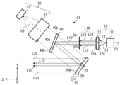
- FIG. 2 is a configuration diagram showing a schematic configuration of the optical scanning device 101 shown in FIG.
- the optical scanning device 101 includes a laser light source section 10, a scanning mirror 20 as a scanning optical section, a light receiving optical system 30 as a light receiving optical section, and a light splitting element 40 as an optical path guiding section. and
- the laser light source section 10 has a light source 11 and an irradiation optical system 12 .
- the optical axis of the laser light source section 10 will be referred to as "optical axis C1".
- the light source 11 emits laser light L1.
- the light source 11 is, for example, a semiconductor laser light source.
- the output of the light source 11 is, for example, 10 W or more.
- the irradiation optical system 12 collimates the laser light L1 emitted from the light source 11.
- the irradiation optical system 12 is an optical unit that converts the laser beam L1 into parallel light and emits the emitted light L10.
- the irradiation optical system 12 has, for example, a convex lens 12a.
- “collimate” means to collimate the laser beam L1. It is within the range up to 2deg.
- the light splitting element 40 is an optical member that separates the optical path of the outgoing light L10 and the optical path of the return light L20. Assuming that the optical axis of the light receiving optical system 30 is the optical axis C3, the light splitting element 40 rotates around the X axis and is inclined with respect to a plane perpendicular to the optical axis C3. In the example shown in FIG. 2, the light splitting element 40 reflects the emitted light L10 and transmits the return light L20. Specifically, the light splitting element 40 has a reflecting portion 40a and a transmitting portion 40b.
- the reflecting section 40 a reflects the emitted light L 10 emitted from the irradiation optical system 12 and passing through the aperture section 50 to be described later, and directs it toward the scanning mirror 20 .
- the shape of the reflecting portion 40a is, for example, circular.
- the shape of the reflecting portion 40a is not limited to a circular shape, and may be other shapes such as an elliptical shape or a rectangular shape.
- the transmitting part 40b transmits the return light L20 reflected by the scanning mirror 20 and directs it to the light receiving optical system 30.
- the light splitting element 40 is formed, for example, by coating a transparent glass with a reflecting film as the reflecting portion 40a. It should be noted that the light splitting element 40 can be realized without the transmitting portion 40b.
- the light splitting element 40 may be, for example, a micromirror having only the reflecting portion 40a. In this case, the return light L ⁇ b>20 reflected by the scanning mirror 20 passes outside the light splitting element 40 and enters the light receiving optical system 30 .
- the scanning mirror 20 scans the emitted light L10 reflected by the light splitting element 40.
- the scanning mirror 20 reflects the emitted light L10 and directs it toward the object 90 (see FIG. 1).
- Scanning mirror 20 rotates around two axes of rotation 21 , 22 .
- the scanning mirror 20 illuminates the object 90 by changing the emission direction of the emission light L10.
- the two rotation axes 21, 22 are parallel to a plane perpendicular to the normal to the reflecting surface 20a of the scanning mirror 20 and perpendicular to each other.
- the scanning mirror 20 two-dimensionally scans the emitted light L10.
- the scanning mirror 20 is, for example, a MEMS (Micro Electro Mechanical Systems) mirror.
- the emitted light L10 scanned by the scanning mirror 20 is applied to the optical scanning area where the object 90 is located.
- the light receiving optical system 30 detects the return light L20 reflected by the scanning mirror 20.
- the light receiving optical system 30 has a light collecting optical section 31 and a light receiving element 32 .
- the condensing optical section 31 is arranged on the optical path of the return light L20 that has passed through the light splitting element 40 .
- the light collection optical unit 31 collects the return light L20 that has passed through the light splitting element 40 and directs it to the light receiving element 32 . Thereby, the detection accuracy of the returned light L20 in the light receiving element 32 can be improved.
- the condensing optical section 31 includes, for example, a condensing lens.
- the light receiving element 32 detects the returned light L20.
- the light receiving element 32 is, for example, a photodiode such as an APD (Avalanche Photo Diode) or a single photon APD, or SiPM (Silicon Photo Multipliers). Since APD, single-photon APD and SiPM have high sensitivity, even if the object 90 (see FIG. 1) is located far from the rangefinder 100 and the reflectance at the object 90 is low, , the return light L20 can be detected. Therefore, since the distance that can be measured by rangefinder 100 increases, rangefinder 100 can acquire an accurate range image of object 90 over a wider range.
- APD Anavalanche Photo Diode
- SiPM Silicon Photo Multipliers
- the optical scanning device 101 further has an aperture section 50 (hereinafter also referred to as "first aperture section 50").
- FIG. 3 is a diagram showing the configuration around the aperture section 50 of the optical scanning device 101 shown in FIG.
- the laser light source section 10 , the aperture section 50 and the light splitting element 40 constitute a light transmission optical system 110 of the light scanning device 101 .
- the aperture section 50 is arranged on the optical path of the emitted light L10 from the laser light source section 10 toward the light splitting element 40 .
- the aperture section 50 reduces the diameter of the emitted light L10 emitted from the irradiation optical system 12 .
- the aperture section 50 has an opening 50a (hereinafter also referred to as "first opening 50a") as a first light passing section.
- the aperture 50a is smaller than the diameter of the emitted light L10.
- the aperture 50a allows a portion of the emitted light L10 including the central luminous flux L11, which is part of the light, to pass therethrough.
- the central luminous flux L11 is a luminous flux containing the central ray of the emitted light L10.
- the central luminous flux L11 is a luminous flux that travels on the optical axis C1 and in the vicinity of the optical axis C1 in the emitted light L10.
- the central luminous flux L11 may include a ray that travels parallel to the optical axis C1 and a ray that travels non-parallel to the optical axis C1 in a region near the optical axis C1.
- the aperture 50a is preferably smaller than the diameter Ah of the reflecting portion 40a of the light splitting element 40.
- the opening 50a is circular, for example. Note that the opening 50a is not limited to a circular shape, and may be oval or rectangular.
- the aperture section 50 further has a light shielding section 50b as a first light shielding section arranged outside the opening 50a.
- a light shielding section 50b as a first light shielding section arranged outside the opening 50a.
- the light splitting element 40 has the reflecting portion 40a that directs the emitted light L10 toward the scanning mirror 20. As shown in FIG. In order to extend the measurable distance, it is necessary to narrow the area of the reflecting portion 40a. In other words, in order to extend the measurable distance, it is necessary to reduce the diameter of the emitted light L10 incident on the light splitting element 40 (hereinafter also referred to as "beam diameter").
- Range finder 100 is provided with aperture section 50 shown in FIGS. 2 and 3 in order to reduce the beam diameter while suppressing the divergence angle of emitted light L10.
- the light splitting element 40 is arranged within the field of view of the light receiving optical system 30 .
- the light splitting element 40 is arranged on the optical path of the return light L20 from the scanning mirror 20 toward the light receiving optical system 30.
- the reflecting portion 40a of the light splitting element 40 is used as an aperture portion for limiting the beam diameter, there is a possibility that a large amount of stray light will be generated.
- an example of the light receiving element 32 is an element with high light sensitivity such as APD or SiPM. Therefore, the light-receiving element 32 detects even a weak light of about several pW, and therefore, when stray light occurs, the accuracy of distance measurement deteriorates. For example, when measuring the distance to the object 90 close to the distance measuring device 100, if stray light occurs, it becomes difficult for the light receiving element 32 to distinguish between the stray light and the returned light L20. Therefore, the measurable distance to the object 90 is reduced.
- the aperture section 50 makes the beam diameter of the emitted light L10 incident on the light splitting element 40 smaller than the beam diameter of the emitted light L10 emitted from the laser light source section 10 . As a result, it is possible to extend the measurable distance while improving the resolution of the ranging azimuth in the ranging device 100 . Further, in the distance measuring device 100 according to the embodiment, the resolution of the distance measurement direction can be improved with a low-cost and compact configuration without increasing the thickness of the irradiation optical system 12 in the Z-axis direction.
- the computer 102 has a controller 102a as a control unit, a calculator 102b, and a storage device 102c.
- the controller 102a and arithmetic unit 102b are provided in a processor such as a CPU (Central Processing Unit), a GPU (Graphics Processing Unit), or an FPGA (Field-Programmable Gate Array).
- the storage device 102c is, for example, a ROM (Read On Memory) or a hard disk.
- the controller 102a is communicably connected to the light source 11, the scanning mirror 20 and the light receiving element 32.
- the controller 102 a controls the optical scanning device 101 .
- the content of control by the controller 102a will be described later.
- a calculator 102b generates a distance image.
- the distance image generated by the calculator 102b includes the distance between the distance measuring device 100 and the object 90 and the direction of the object 90 viewed from the distance measuring device 100.
- the calculator 102b outputs a signal for the distance image to a display device (not shown).
- the display device is communicatively connected to computer 102 (eg, storage device 102c). The display device displays the distance image.
- a housing 103 accommodates the optical scanning device 101 and the computer 102 .
- the housing 103 has a transparent window 103a.
- the transparent window 103a allows the outgoing light L10 emitted from the optical scanning device 101 and the return light L20 reflected or scattered by the object 90 to pass therethrough.
- the transparent window 103a may be formed of a wavelength filter having a wavelength different from the wavelengths of the emitted light L10 and the returned light L20. Thereby, unnecessary light can be blocked.
- the computer 102 can be implemented without being accommodated in the housing 103.
- FIG. In this case, the computer 102 may be arranged outside the housing 103 .
- a controller 102 a controls the light source 11 . Thereby, the emission timing of the laser beam L1 is controlled.
- the controller 102a receives from the light source 11 a signal indicating the time when the light source 11 emitted the laser beam L1 (hereinafter also referred to as “first timing”).
- the controller 102 a controls the scanning mirror 20 .
- the controller 102a receives a signal from the scanning mirror 20 indicating the tilt angle of the scanning mirror 20 (for example, the tilt of the normal to the reflecting surface 20a of the scanning mirror 20).
- the controller 102 a also receives from the light receiving element 32 a signal indicating the amount of the returned light L ⁇ b>20 received by the light receiving element 32 .
- the controller 102a also receives from the light receiving element 32 a signal indicating the time when the light receiving element 32 detected the returned light L20 (hereinafter also referred to as “second timing”).
- the calculator 102b calculates the emission direction of the emitted light L10 based on the tilt of the scanning mirror 20 received by the controller 102a and the position of the light source 11 with respect to the scanning mirror 20 stored in advance in the storage device 102c.
- the calculator 102b receives the signal indicating the first timing and the signal indicating the second timing from the controller 102a.
- the calculator 102b calculates the distance between the rangefinder 100 and the target 90 and the position of the target 90 with respect to the rangefinder 100 based on the calculated output direction of the emitted light L10, the first timing, and the second timing. calculate.
- the distance measuring device 100 is arranged on the optical path of the emitted light L10 from the laser light source section 10 toward the reflecting section 40a of the light splitting element 40, and reduces the diameter of the emitted light L10. It has an aperture section 50 . This prevents the emitted light L10 from being scattered and diffracted when it enters the light splitting element 40, thereby improving the resolution of the range finding direction. In addition, scattered light and diffracted light of the emitted light L10 are prevented from entering the light receiving optical system 30 as stray light, so that the measurable distance can be extended. Therefore, in the ranging device 100 according to the embodiment, it is possible to extend the measurable distance while improving the resolution of the ranging azimuth.
- the aperture section 50 has an opening 50a that allows a portion including the central luminous flux of the emitted light L10 to pass therethrough, and a light shielding section 50b arranged outside the opening 50a.
- the aperture section 50 can reduce the diameter of the emitted light L10 when entering the light splitting element 40 .
- FIG. 4 is a configuration diagram showing the configuration of a distance measuring device 200 according to Modification 1 of the embodiment. 4, the same or corresponding components as those shown in FIG. 2 are given the same reference numerals as those shown in FIG.
- a range finder 200 according to Modification 1 of the embodiment differs from the range finder 100 according to the embodiment in that it further includes a second aperture section 60 . Apart from this, rangefinder 200 according to Modification 1 of the embodiment is the same as rangefinder 100 according to the embodiment.
- the distance measuring device 200 includes a laser light source section 10, a scanning mirror 20, a light receiving optical system 30, a light splitting element 40, a first aperture section 50, and a second aperture section. 60.
- the second aperture section 60 is arranged on the optical path of the emitted light L10 from the first aperture section 50 toward the light splitting element 40 .
- FIG. 5 is a diagram showing the configuration around the first aperture section 50 and the second aperture section 60 shown in FIG.
- the second aperture section 60 includes a second opening 60a as a second light passing section and a second light blocking section 60b arranged outside the second opening 60a.
- the opening width A2 of the second opening 60a is larger than the opening width A1 of the first opening 50a.
- the light intensity distribution of the emitted light L10 that has passed through the first opening 50a is Affected by Fresnel diffraction. Since the aperture width A2 is larger than the aperture width A1, the diffracted light of the emitted light L10 generated by passing through the first aperture 50a can be blocked.
- the aperture width A2 is smaller than the diameter Ah (see FIG. 3) of the reflecting portion 40a of the light splitting element 40.
- the second opening 60a is circular, for example.
- the second opening 60a is not limited to a circular shape, and may be oval or other shapes such as the above-described rectangular shape.
- each of the first aperture section 50 and the second aperture section 60 is preferably, for example, 2.0 mm or less. This can suppress the occurrence of diffraction when the emitted light L10 passes through the first opening 50a and the second opening 60a.
- first aperture section 50 and the second aperture section 60 are separated from each other. It is preferably 0 mm or more. In the example shown in FIG. 5, for example, the distance between the first aperture section 50 and the second aperture section 60 is 15 mm.
- FIG. 6 is a graph showing light intensity distributions D1, D2, and D3 of emitted light L10.
- the horizontal axis indicates the position [mm] at which the light intensity was measured, and the vertical axis indicates the light intensity [a. u. ] is shown.
- the light intensity distribution D1 is obtained when the first aperture 50a has a rectangular shape of 3.0 mm ⁇ 3.0 mm and the distance between the first aperture section 50 and the light splitting element 40 is 35 mm.
- 4 shows the light intensity distribution of emitted light L10 measured on the splitting element 40.
- the emitted light L10 has a wavelength of 905 nm, and the emitted light L10 emitted from the light source 11 is collimated by the irradiation optical system 12 .
- the second aperture section 60 is not provided. Therefore, the light intensity distribution D1 is shifted from the position corresponding to the outer edge of the first opening 50a on the light splitting element 40 (that is, ⁇ 1. 5 mm). In this case, when the emitted light L10 enters the light splitting element 40, it leaks from the reflecting portion 40a and becomes stray light.
- the light intensity distribution D2 is the light intensity distribution at a position 15 mm away from the first aperture section 50 in the +Z-axis direction (that is, the emission direction of the emission light L10).
- the second aperture section 60 is arranged at a position 15 mm away from the first aperture section 50 in the +Z-axis direction, and the second opening 60a has a rectangular shape of 3.1 mm ⁇ 3.1 mm. 4 shows the light intensity distribution of emitted light L10 measured on the light splitting element 40 in a certain case.
- the light intensity in the area outside the position corresponding to the outer edge of the first opening 50a on the light splitting element 40 is smaller than that in the light intensity distribution D1.
- the diffracted light generated when the emitted light L10 passes through the first opening 50a is It can enter the light splitting element 40 as stray light. Even if the light intensity distribution of the emitted light L10 has another shape such as a Gaussian shape, the same tendency as described above is observed.
- Equation (1) A is the amplitude, i is the imaginary unit, k is the wave number, (x, y) are the coordinates on the aperture, and (x', y') are the coordinates at a distance R from the aperture. show. It is preferable that the second aperture section 60 is arranged at a position where the value of the left side of Equation (1) is 1 ⁇ 5 or less of the peak intensity of the emitted light L10.
- the second aperture section 60 is arranged at a position where it does not overlap with the return light L20 reflected by the scanning mirror 20 . As a result, blocking of the return light L20 by the second aperture section 60 can be prevented.
- the distance measuring device 200 is arranged on the optical path of the emitted light L10 from the laser light source unit 10 toward the reflecting portion 40a of the light splitting element 40, and the emitted light L10 It has a first aperture portion 50 that reduces the diameter. This prevents the emitted light L10 from being scattered and diffracted when it enters the light splitting element 40, thereby improving the resolution of the range finding direction. In addition, scattered light and diffracted light of the emitted light L10 are prevented from entering the light receiving optical system 30 as stray light, so that the measurable distance can be extended. Therefore, in the ranging device 200, it is possible to extend the measurable distance while improving the resolution of the ranging azimuth.
- the distance measuring device 200 further includes the second aperture section 60 arranged on the optical path from the first aperture section 50 to the light splitting element 40.
- the second opening 60 a of the second aperture section 60 is larger than the first opening 50 a of the first aperture section 50 .
- the second aperture section 60 can shield the diffracted light of the output light L10 generated by passing through the first opening 50a. Therefore, in the distance measuring device 200 according to Modification 1 of the embodiment, it is possible to further increase the measurable distance while further improving the resolution of the distance measurement azimuth.
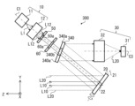
- FIG. 7 is a configuration diagram showing a schematic configuration of a distance measuring device 300 according to Modification 2 of the embodiment. 7, the same or corresponding components as those shown in FIG. 2 or 4 are given the same reference numerals as those shown in FIG.
- the distance measuring device 300 includes a laser light source section 10, a scanning mirror 20, a light receiving optical system 30, a light splitting element 340, a first aperture section 50, and a second aperture section. 60.
- the light splitting element 340 has a reflecting portion 340a and a transmitting portion 340b.
- the reflecting part 340 a reflects the return light L 20 reflected by the scanning mirror 20 and directs it to the light receiving optical system 30 .
- the return light L20 reflected by the scanning mirror 20 is reflected by the light splitting element 40 and enters the light receiving optical system 30 .
- the transmission part 340 b transmits the emitted light L 10 emitted from the irradiation optical system 12 and directs it to the scanning mirror 20 .
- the transmissive portion 340b is, for example, a hole passing through the light splitting element 340.
- the light splitting element 340 is, for example, a perforated mirror.
- the light splitting element 340 may be a reflecting mirror in which a transparent glass is coated with a reflecting film as the reflecting portion 340a. Also, the light splitting element 340 can be realized without having the transmitting portion 340b.
- the emitted light L10 incident on the light splitting element 340 would pass through the inner surface of the hole, which is the transmission section 340b (that is, edge), and scattered light may be generated. Moreover, diffracted light may be generated when the emitted light L10 passes through the hole. Scattered light and diffracted light enter the light receiving optical system 30 as stray light.
- the first aperture section 50 is arranged on the optical path of the emitted light L10 from the laser light source section 10 toward the light splitting element 340 to reduce the diameter of the emitted light L10. This prevents the emitted light L10 from being scattered and diffracted when it enters the light splitting element 340, thereby improving the resolution of the distance measurement direction. Moreover, since the scattered light and the diffracted light are prevented from entering the light receiving optical system 30 as stray light, the measurable distance can be extended. Therefore, even in a configuration in which the emitted light L10 emitted from the laser light source unit 10 passes through the light splitting element 340 and the return light L20 is reflected by the light splitting element 340, the resolution of the ranging direction is improved. It can extend the measurable distance.
- the distance measuring device 300 further has a second aperture section 60 arranged on the optical path from the first aperture section 50 to the light splitting element 340 .
- the second opening 60 a of the second aperture section 60 is larger than the first opening 50 a of the first aperture section 50 .
- the second aperture section 60 can shield the diffracted light of the output light L10 that is generated when passing through the first opening 50a.
- FIG. 8 is a diagram of another example of the first aperture section 351 of the distance measuring device 300 according to Modification 2 of the embodiment, viewed in the Z-axis direction.
- the first aperture portion 351 has a light transmitting portion 350a as a light passing portion, a light shielding portion 350b, and a boundary region 350c as a first boundary region.
- the light transmitting portion 350a allows a portion including the central luminous flux of the emitted light L10 to pass therethrough.
- the shape of the light transmitting portion 350a when viewed in the Z-axis direction is, for example, circular.
- the light shielding portion 350b is arranged outside the light transmitting portion 350a and shields peripheral rays of the emitted light L10.
- the light shielding part 350b is, for example, a metal film deposited on transparent glass.
- the boundary region 351c is arranged between the light transmitting portion 350a and the light shielding portion 350b.
- the boundary area 351c is, for example, annular.
- the transmittance of the emitted light L10 in the boundary region 351c increases as it approaches the light transmitting portion 350a and decreases as it approaches the light blocking portion 350b.
- the transmittance has a gradient. Accordingly, when the emitted light L10 emitted from the laser light source section 10 passes through the light transmission section 350a of the first aperture section 351, scattering and diffraction can be prevented.
- the width of the boundary region 351c is preferably about 5% of the diameter of the light transmitting portion 350a.
- the second aperture section 60 has a second boundary area disposed between the light transmission section and the light shielding section, and the transmittance of the second boundary area increases as it approaches the light transmission section. It may be.
- FIG. 9 is a diagram of still another example of the first aperture section 352 of the distance measuring device 300 according to Modification 2 of the embodiment, viewed in the Z-axis direction.
- the first aperture section 352 has an opening 50a and a light blocking section 352b arranged outside the opening 50a.
- a plurality of convex parts 352d are arranged, the width of which narrows as it approaches the opening 50a.
- the inner surface 352s has a sawtooth shape. Accordingly, when the emitted light L10 emitted from the laser light source section 10 passes through the first aperture section 352, it is possible to prevent scattering and diffraction from occurring on the inner surface 352s surrounding the opening 50a.
- a plurality of protrusions may be arranged on the inner surface surrounding the opening 60a of the second aperture section 60, the width of which becomes narrower as it approaches the opening 60a.
- the distance measuring device 300 is arranged on the optical path of the emitted light L10 from the laser light source unit 10 toward the transmission portion 340b of the light splitting element 340. It has a first aperture portion 50 that reduces the diameter. This prevents the emitted light L10 from being scattered and diffracted when it enters the light splitting element 340, thereby improving the resolution of the distance measurement direction. In addition, scattered light and diffracted light of the emitted light L10 are prevented from entering the light receiving optical system 30 as stray light, so that the measurable distance can be extended. Therefore, in the ranging device 300, the measurable distance can be extended while improving the resolution of the ranging azimuth.
- the first aperture portion 351 has the boundary region 351c arranged between the light transmission portion 350a and the light blocking portion 350b, and the emitted light L10 in the boundary region 351c
- the transmittance of becomes higher as it approaches the light transmitting portion 350a.
- FIG. Therefore, in the distance measuring device 300, it is possible to further improve the resolution of the distance measurement direction and further extend the distance that can be measured.
- the inner surface 352s of the first aperture portion 352 surrounding the opening 50a is provided with a plurality of convex portions 352d that become narrower toward the opening 50a. Accordingly, when the emitted light L10 emitted from the laser light source section 10 passes through the first aperture section 352, it is possible to prevent scattering and diffraction from occurring on the inner surface 352s. Therefore, in the distance measuring device 300, it is possible to further improve the resolution of the distance measurement direction and further extend the distance that can be measured.
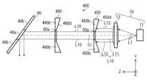
- FIG. 10 is a configuration diagram showing a schematic configuration of distance measuring device 400 according to Modification 3 of the embodiment. 10, the same or corresponding components as those shown in FIG. 5 are given the same reference numerals as those shown in FIG.
- Range finder 400 according to Modification 3 of the embodiment differs from range finder 200 according to Modification 1 of the embodiment in terms of the shapes of first aperture section 450 and second aperture section 460. do.
- rangefinder 400 according to Modification 3 of the embodiment is the same as rangefinder 200 according to Modification 1 of the embodiment. Therefore, FIG. 4 will be referred to in the following description.
- a distance measuring device 400 includes a laser light source unit 10, a scanning mirror 20 (see FIG. 4), a light receiving optical system 30 (see FIG. 4), a light splitting element 40, and a first It has an aperture section 450 and a second aperture section 460 .
- the first aperture part 450 is a plate-like member that becomes thinner as it approaches the first opening 50a. Accordingly, when the emitted light L10 emitted from the laser light source unit 10 passes through the first opening 50a, it is possible to suppress scattering and diffraction on the inner surface surrounding the first opening 50a.
- a surface 450d of the first aperture section 450 on the side of the laser light source section 10 is inclined in a direction away from the laser light source section 10 as it approaches the first opening 50a.
- the second aperture part 460 is a plate-like member that becomes thinner as it approaches the second opening 60a. This can suppress scattering and diffraction on the inner surface surrounding the second opening 60a when the emitted light L10 that has passed through the first opening 50a passes through the second opening 60a.
- a surface 460d of the second aperture section 460 on the first aperture section 450 side is inclined away from the first aperture section 450 as the second opening 60a is approached. At least one of the first aperture portion 450 and the second aperture portion 460 should be thinner as it approaches the opening.
- the first aperture portion 450 is a plate-like member that becomes thinner as it approaches the first opening 50a. Accordingly, when the emitted light L10 emitted from the laser light source unit 10 passes through the first opening 50a, scattering and diffraction on the inner surface surrounding the first opening 50a can be suppressed. Therefore, in the ranging device 400, the measurable distance can be extended while improving the resolution of the ranging azimuth.
- the second aperture portion 460 is a plate-like member that becomes thinner as it approaches the second opening 60a. Accordingly, when the emitted light L10 that has passed through the first opening 50a passes through the second opening 60a, scattering and diffraction on the inner surface surrounding the second opening 60a can be suppressed. Therefore, in the distance measuring device 400, it is possible to further increase the measurable distance while further improving the resolution of the distance measurement direction.
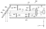
- FIG. 11 is a configuration diagram showing a schematic configuration of a distance measuring device 500 according to Modification 4 of the embodiment. 11, the same or corresponding components as those shown in FIG. 5 are given the same reference numerals as those shown in FIG.
- Range finder 500 according to Modification 4 of the embodiment differs from range finder 200 according to Modification 1 of the embodiment in terms of the shapes of first aperture section 450 and second aperture section 460. do. Except for this point, rangefinder 500 according to Modification 4 of the embodiment is the same as rangefinder 200 according to Modification 1 of the embodiment. Therefore, FIG. 4 will be referred to in the following description.
- a distance measuring device 500 includes a laser light source unit 10, a scanning mirror 20 (see FIG. 4), a light receiving optical system 30 (see FIG. 4), a light splitting element 40, and a first It has an aperture portion 550 , a second aperture portion 560 , a first aperture holding member 571 and a second aperture holding member 572 .
- the first aperture portion 550 has a plate portion 551 as a first plate portion and a plate portion 552 as a second plate portion.
- the plate portion 551 is held by a first aperture holding member 571 .
- the plate portion 552 is held by a second aperture holding member 572 .
- the first aperture holding member 571 and the second aperture holding member 572 may be formed integrally with a member holding another optical member such as the lens or the light splitting element 40 .
- the plate portions 551 and 552 are arranged with the emitted light L10 interposed therebetween. A portion of the emitted light L10 that includes the central luminous flux passes through the opening 50a that is the gap formed between the plate portions 551 and 552 . Further, the peripheral light beam L12 of the emitted light beam L10 that travels away from the optical axis C1 is shielded by the plate portions 551 and 552 . Thereby, the first aperture section 550 can reduce the diameter of the emitted light L10 directed from the laser light source section 10 toward the light splitting element 40 . As a result, the ranging device 500 can extend the measurable distance while improving the resolution of the ranging azimuth.
- the aperture portion is integrated with a member (that is, another holding structure) that holds another optical member such as the lens or the light splitting element 40.
- a member that is, another holding structure
- another optical member such as the lens or the light splitting element 40.
- a method of forming is conceivable.
- the aperture section is integrally formed with another holding structure, the processing becomes difficult, and thus it becomes difficult to form an opening in the aperture section.
- the aperture portion having the opening is a separate part and fixed to the aperture holding member with a screw or the like, the positional accuracy of the aperture portion is deteriorated.
- the portion of the first aperture portion 550 that shields the peripheral ray L12 of the emitted light L10 is divided.
- the plate portion 552 is displaced from the plate portion 551 in the emission direction of the emission light L10 (that is, the Z-axis direction).
- the positional accuracy of the first aperture section 550 can be improved, and stray light can be prevented from occurring.
- formation of the opening 50a in the first aperture portion 550 is facilitated.
- the second aperture portion 560 has a plate portion 561 as a first plate portion and a plate portion 562 as a second plate portion.
- the plate portion 561 is held by a first aperture holding member 571 .
- the plate portion 562 is held by a second aperture holding member 572 .
- the plate portions 561 and 562 are arranged with the emitted light L10 interposed therebetween.
- the emitted light L10 that has passed through the first aperture section 550 passes through the opening 60a that is the gap formed between the plate section 561 and the plate section 562 .
- Opening 60a is larger than opening 50a.
- the plate portions 561 and 562 can shield the diffracted light of the output light L10 generated by passing through the opening 50a.
- the portion of the second aperture portion 560 that shields the diffracted light of the output light L10 is also divided.
- the plate portion 562 is arranged to be displaced from the plate portion 561 in the emission direction of the emission light L10 (that is, the Z-axis direction).
- the positional accuracy of the second aperture portion 560 can be improved, and stray light can be prevented from occurring.
- formation of the opening 60a in the second aperture portion 560 is facilitated.
- FIG. 12 is a view of another example of the first aperture section 550A of the distance measuring device 400 according to Modification 4 of the embodiment, viewed in the Z-axis direction.
- the first aperture portion 550A includes a first plate portion 551A and a second plate portion 552A that is displaced from the first plate portion 551A in the +Z-axis direction. have.
- the second plate portion 552A has a through portion 550e penetrating in the Z-axis direction.
- the first plate portion 551A partially overlaps the penetrating portion 550e.
- part of the penetrating portion 550e is blocked by the first plate portion 551A.
- a portion of the emitted light L10 emitted from the laser light source unit 10 passes through a region of the through portion 550e that is not blocked by the first plate portion 551A.
- the first aperture portion 550A can reduce the diameter of the emitted light L10. Therefore, scattering and diffraction are prevented when the emitted light L10 is incident on the light splitting element 40, that is, stray light is prevented from occurring. You can extend the distance.
- the portion of the first aperture portion 550A that shields the peripheral ray L12 of the emitted light L10 is divided.
- the positional accuracy of the first aperture portion 550A can be improved, and the occurrence of stray light can be prevented.
- the second aperture section 560 may have the same configuration as the first aperture section 550A shown in FIG.
- the first aperture portion 550 includes the plate portion 551 and the plate portion 552 that is displaced from the plate portion 551 in the emission direction of the emitted light L10. , and emitted light L10 directed from the laser light source unit 10 toward the light splitting element 340 passes between the plate portions 551 and 552 .
- the positional accuracy of the first aperture section 550 can be improved, and stray light can be prevented from occurring.
- the second aperture portion 560 has a plate portion 561 and a plate portion 562 that is displaced from the plate portion 561 in the emission direction of the emitted light L10. Then, the emitted light L10 directed from the first aperture portion 550 to the light splitting element 340 passes between the plate portion 561 and the plate portion 562 . As a result, the positional accuracy of the second aperture portion 560 can be improved, and stray light can be prevented from occurring.
- the first aperture portion 550A is arranged to shift from the first plate portion 551A and the first plate portion 551A in the emission direction of the emitted light L10. and a second plate portion 552A.
- the second plate portion 552A has a through portion 550e through which the emitted light L10 passes, and the first plate portion 551A partially overlaps with the through portion 550e when viewed in the emission direction of the emitted light L10.
- Laser light source unit 11 Light source 12 Irradiation optical system 12a Convex lens 20 Scanning mirror 20a Reflecting surface 21, 22 Rotating shaft 30
- Light receiving optical system 31 Condensing optical unit 32
- Light receiving element 40 340 Light splitting Elements 40a, 340a Reflective portions 40b, 340b Transmissive portions 50, 351, 352, 450, 550, 550A First aperture portions 50a, 550a First openings 50b, 350b, 352b
- Distance measuring device 101 Optical scanning device 102 Computer 102a Controller 102b Arithmetic unit 102c Storage device 103 Housing 103a Transparent window 110
- Light transmission optical system 350a Light transmission part 351c Boundary area 352d Convex part 352s Inner surface 450d, 460d Surface 550c, 550e Through part 551, 551A, 552,
Landscapes
- Engineering & Computer Science (AREA)
- Physics & Mathematics (AREA)
- Computer Networks & Wireless Communication (AREA)
- General Physics & Mathematics (AREA)
- Radar, Positioning & Navigation (AREA)
- Remote Sensing (AREA)
- Electromagnetism (AREA)
- Optical Radar Systems And Details Thereof (AREA)
Priority Applications (4)
| Application Number | Priority Date | Filing Date | Title |
|---|---|---|---|
| PCT/JP2021/028256 WO2023007694A1 (ja) | 2021-07-30 | 2021-07-30 | 測距装置 |
| DE112021008064.4T DE112021008064T5 (de) | 2021-07-30 | 2021-07-30 | Entfernungsmessvorrichtung |
| JP2022553198A JP7311718B2 (ja) | 2021-07-30 | 2021-07-30 | 測距装置 |
| US18/578,016 US20240310519A1 (en) | 2021-07-30 | 2021-07-30 | Distance measuring apparatus |
Applications Claiming Priority (1)
| Application Number | Priority Date | Filing Date | Title |
|---|---|---|---|
| PCT/JP2021/028256 WO2023007694A1 (ja) | 2021-07-30 | 2021-07-30 | 測距装置 |
Publications (1)
| Publication Number | Publication Date |
|---|---|
| WO2023007694A1 true WO2023007694A1 (ja) | 2023-02-02 |
Family
ID=85086581
Family Applications (1)
| Application Number | Title | Priority Date | Filing Date |
|---|---|---|---|
| PCT/JP2021/028256 Ceased WO2023007694A1 (ja) | 2021-07-30 | 2021-07-30 | 測距装置 |
Country Status (4)
| Country | Link |
|---|---|
| US (1) | US20240310519A1 (https=) |
| JP (1) | JP7311718B2 (https=) |
| DE (1) | DE112021008064T5 (https=) |
| WO (1) | WO2023007694A1 (https=) |
Citations (7)
| Publication number | Priority date | Publication date | Assignee | Title |
|---|---|---|---|---|
| JPH0519206A (ja) * | 1990-10-26 | 1993-01-29 | Toyo Ink Mfg Co Ltd | 光ビームのサイズ制御方法 |
| JP2003139534A (ja) * | 2001-10-30 | 2003-05-14 | Pentax Corp | 光波測距儀 |
| JP2004170965A (ja) * | 2002-11-07 | 2004-06-17 | Fuji Photo Optical Co Ltd | 集光光学系 |
| JP2013254661A (ja) * | 2012-06-07 | 2013-12-19 | Omron Corp | 光電センサ |
| JP2014519697A (ja) * | 2011-04-15 | 2014-08-14 | オスラム オプト セミコンダクターズ ゲゼルシャフト ミット ベシュレンクテル ハフツング | 光電子装置 |
| JP2019518204A (ja) * | 2016-12-31 | 2019-06-27 | イノビュージョン アイルランド リミテッドInnovusion Ireland Limited | 回転凹面鏡及びビームステアリング装置の組み合わせを用いた、2d走査型高精度ライダー |
| US20190377068A1 (en) * | 2018-06-10 | 2019-12-12 | Apple Inc. | Patterned mirror edge for stray beam and interference mitigation |
Family Cites Families (4)
| Publication number | Priority date | Publication date | Assignee | Title |
|---|---|---|---|---|
| US4954962A (en) * | 1988-09-06 | 1990-09-04 | Transitions Research Corporation | Visual navigation and obstacle avoidance structured light system |
| JP5101955B2 (ja) | 2006-09-20 | 2012-12-19 | 株式会社ミツトヨ | 形状測定方法及び形状測定装置 |
| JP2015022158A (ja) * | 2013-07-19 | 2015-02-02 | 株式会社リコー | 光走査装置および画像表示装置 |
| JP6363396B2 (ja) | 2014-05-23 | 2018-07-25 | スカラ株式会社 | 光ポインタ |
-
2021
- 2021-07-30 US US18/578,016 patent/US20240310519A1/en active Pending
- 2021-07-30 DE DE112021008064.4T patent/DE112021008064T5/de active Pending
- 2021-07-30 JP JP2022553198A patent/JP7311718B2/ja active Active
- 2021-07-30 WO PCT/JP2021/028256 patent/WO2023007694A1/ja not_active Ceased
Patent Citations (7)
| Publication number | Priority date | Publication date | Assignee | Title |
|---|---|---|---|---|
| JPH0519206A (ja) * | 1990-10-26 | 1993-01-29 | Toyo Ink Mfg Co Ltd | 光ビームのサイズ制御方法 |
| JP2003139534A (ja) * | 2001-10-30 | 2003-05-14 | Pentax Corp | 光波測距儀 |
| JP2004170965A (ja) * | 2002-11-07 | 2004-06-17 | Fuji Photo Optical Co Ltd | 集光光学系 |
| JP2014519697A (ja) * | 2011-04-15 | 2014-08-14 | オスラム オプト セミコンダクターズ ゲゼルシャフト ミット ベシュレンクテル ハフツング | 光電子装置 |
| JP2013254661A (ja) * | 2012-06-07 | 2013-12-19 | Omron Corp | 光電センサ |
| JP2019518204A (ja) * | 2016-12-31 | 2019-06-27 | イノビュージョン アイルランド リミテッドInnovusion Ireland Limited | 回転凹面鏡及びビームステアリング装置の組み合わせを用いた、2d走査型高精度ライダー |
| US20190377068A1 (en) * | 2018-06-10 | 2019-12-12 | Apple Inc. | Patterned mirror edge for stray beam and interference mitigation |
Also Published As
| Publication number | Publication date |
|---|---|
| US20240310519A1 (en) | 2024-09-19 |
| JP7311718B2 (ja) | 2023-07-19 |
| DE112021008064T5 (de) | 2024-07-25 |
| JPWO2023007694A1 (https=) | 2023-02-02 |
Similar Documents
| Publication | Publication Date | Title |
|---|---|---|
| US12078530B2 (en) | Light detection using an aperture | |
| CN111398933B (zh) | 激光雷达探测系统及激光雷达 | |
| JP2004521355A (ja) | 光学的距離測定装置 | |
| EP2339366B1 (en) | Optical distance measuring device | |
| US11852852B2 (en) | Patterned mirror edge for stray beam and interference mitigation | |
| JP5452245B2 (ja) | 光波距離測定装置 | |
| JP2007514942A (ja) | 遠方・近接物体との距離測定装置 | |
| JP7311718B2 (ja) | 測距装置 | |
| JP7596875B2 (ja) | 生体情報取得装置 | |
| JP2006053055A (ja) | レーザ測定装置 | |
| US5815272A (en) | Filter for laser gaging system | |
| JP2001021480A (ja) | フローセル及びこのフローセルを用いた粒子測定装置 | |
| JPH10246616A (ja) | 多心テープ光ファイバの表面状態観測方法、表面異状検出方法および表面状態測定装置 | |
| JP7170251B2 (ja) | 距離測定装置 | |
| JP2595315B2 (ja) | 光散乱式計測装置 | |
| JPH07146115A (ja) | 光センサ | |
| JP6735463B2 (ja) | 計測装置 | |
| CN224152644U (zh) | 接收模组和激光雷达 | |
| JPS6244649A (ja) | 粒子解析装置 | |
| US11372109B1 (en) | Lidar with non-circular spatial filtering | |
| EP4446778A1 (en) | Improved lidar imaging device | |
| KR100749829B1 (ko) | 3차원 광측정장치 | |
| JPWO2023007694A5 (https=) | ||
| WO2025182999A1 (ja) | 粒子計測装置及び粒子計測方法 | |
| JP2019082456A (ja) | 光学式センサチップ及び光学式ガスセンサ |
Legal Events
| Date | Code | Title | Description |
|---|---|---|---|
| ENP | Entry into the national phase |
Ref document number: 2022553198 Country of ref document: JP Kind code of ref document: A |
|
| 121 | Ep: the epo has been informed by wipo that ep was designated in this application |
Ref document number: 21951894 Country of ref document: EP Kind code of ref document: A1 |
|
| WWE | Wipo information: entry into national phase |
Ref document number: 112021008064 Country of ref document: DE |
|
| 122 | Ep: pct application non-entry in european phase |
Ref document number: 21951894 Country of ref document: EP Kind code of ref document: A1 |