WO2023007694A1 - 測距装置 - Google Patents
測距装置 Download PDFInfo
- Publication number
- WO2023007694A1 WO2023007694A1 PCT/JP2021/028256 JP2021028256W WO2023007694A1 WO 2023007694 A1 WO2023007694 A1 WO 2023007694A1 JP 2021028256 W JP2021028256 W JP 2021028256W WO 2023007694 A1 WO2023007694 A1 WO 2023007694A1
- Authority
- WO
- WIPO (PCT)
- Prior art keywords
- light
- section
- emitted
- aperture
- measuring device
- Prior art date
Links
Images


Classifications
-
- G—PHYSICS
- G01—MEASURING; TESTING
- G01S—RADIO DIRECTION-FINDING; RADIO NAVIGATION; DETERMINING DISTANCE OR VELOCITY BY USE OF RADIO WAVES; LOCATING OR PRESENCE-DETECTING BY USE OF THE REFLECTION OR RERADIATION OF RADIO WAVES; ANALOGOUS ARRANGEMENTS USING OTHER WAVES
- G01S7/00—Details of systems according to groups G01S13/00, G01S15/00, G01S17/00
- G01S7/48—Details of systems according to groups G01S13/00, G01S15/00, G01S17/00 of systems according to group G01S17/00
- G01S7/481—Constructional features, e.g. arrangements of optical elements
Definitions
- the present disclosure relates to a rangefinder.
- a range finder irradiates a target area with laser light and detects the presence or absence of an object based on the presence or absence of return light reflected or scattered by the target area. Also, the distance measuring device detects the distance to the object based on the time required from the timing of irradiation of the laser beam to the timing of receiving the return light. See, for example, US Pat.
- the device of Patent Document 1 has a light splitting element that splits the optical path of the laser light and the optical path of the return light.
- the light splitting element of Patent Document 1 is a perforated mirror that transmits laser light.
- Patent Document 1 when the hole of the light splitting element is made small in order to increase the amount of received light, laser light is scattered or diffracted on the inner surface (hereinafter also referred to as "edge") surrounding the hole. do. In this case, since the spot diameter of the laser light becomes large, the resolution of the ranging direction is lowered. In addition, when the scattered light and diffracted light formed by the laser beam passing through the hole enters the light receiving optical system as stray light, it becomes difficult for the light receiving optical system to distinguish between the stray light and the returned light, making distance measurement possible. distance is reduced.
- the present disclosure aims to extend the measurable distance while improving the resolution of the ranging azimuth.
- An optical scanning device is a distance measuring device that detects return light reflected or scattered by an object and measures a distance to the object, comprising: a laser light source unit; a scanning optical unit that scans the emitted light emitted from the scanning optical unit; the emitted light scanned by the scanning optical unit is reflected by the object irradiated with the emitted light; and the return light reflected by the scanning optical unit is detected.
- a light receiving optical section an optical path guide section for directing the emitted light emitted from the laser light source section toward the scanning optical section; and a first aperture portion for reducing the diameter of emitted light.
- FIG. 1 is a configuration diagram showing a schematic configuration of a distance measuring device and an object according to an embodiment
- FIG. 2 is a configuration diagram showing a schematic configuration of the optical scanning device shown in FIG. 1
- FIG. 3 is a diagram showing a configuration around an aperture section shown in FIG. 2
- FIG. 4 is a configuration diagram showing a schematic configuration of a distance measuring device according to Modification 1 of the embodiment
- 5 is a diagram showing a configuration around a first aperture section and a second aperture section shown in FIG. 4
- FIG. 4 is a graph showing a light intensity distribution of emitted light with diffraction.
- FIG. 10 is a configuration diagram showing a schematic configuration of a distance measuring device according to Modification 2 of the embodiment
- FIG. 10 is a configuration diagram showing a schematic configuration of a distance measuring device according to Modification 2 of the embodiment
- FIG. 10 is a view of another example of the first aperture section of the range finder according to Modification 2 of the embodiment, viewed in the Z-axis direction;
- FIG. 11 is a diagram of still another example of the first aperture section of the rangefinder according to Modification 2 of the embodiment, viewed in the Z-axis direction;
- FIG. 11 is a configuration diagram showing a schematic configuration of a distance measuring device according to Modification 3 of the embodiment;
- FIG. 11 is a configuration diagram showing a part of a schematic configuration of a distance measuring device according to Modification 4 of the embodiment;
- FIG. 12 is a view of another example of the first aperture section of the rangefinder according to Modification 4 of the embodiment, viewed in the Z-axis direction;
- a distance measuring device according to an embodiment of the present disclosure will be described below with reference to the drawings.
- the following embodiment is merely an example, and it is possible to combine the embodiment and each modification as appropriate, and to change the embodiment and each modification as appropriate.
- the Z-axis is a coordinate axis parallel to the emission direction of the emitted light emitted from the distance measuring device to the object.
- the X-axis is a coordinate axis orthogonal to the Z-axis.
- the Y-axis is a coordinate axis orthogonal to the X-axis and Z-axis.
- FIG. 1 is a diagram showing a schematic configuration of a distance measuring device 100 and an object 90 according to an embodiment.
- the distance measuring device 100 detects the return light L20 reflected or scattered by the object 90 irradiated with the emitted light L10, and detects the distance to the object 90.
- FIG. The distance measuring device 100 irradiates the object 90 with, for example, single-mode laser light or multi-mode laser light as emitted light L10. Note that the distance measuring device 100 may detect distances to a plurality of objects 90 . Therefore, the rangefinder 100 can detect the distance to at least one target 90 .
- the distance measuring device 100 has an emitted light scanning device (hereinafter also referred to as an "optical scanning device") 101, a computer 102, and a housing 103.
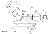
- FIG. 2 is a configuration diagram showing a schematic configuration of the optical scanning device 101 shown in FIG.
- the optical scanning device 101 includes a laser light source section 10, a scanning mirror 20 as a scanning optical section, a light receiving optical system 30 as a light receiving optical section, and a light splitting element 40 as an optical path guiding section. and
- the laser light source section 10 has a light source 11 and an irradiation optical system 12 .
- the optical axis of the laser light source section 10 will be referred to as "optical axis C1".
- the light source 11 emits laser light L1.
- the light source 11 is, for example, a semiconductor laser light source.
- the output of the light source 11 is, for example, 10 W or more.
- the irradiation optical system 12 collimates the laser light L1 emitted from the light source 11.
- the irradiation optical system 12 is an optical unit that converts the laser beam L1 into parallel light and emits the emitted light L10.
- the irradiation optical system 12 has, for example, a convex lens 12a.
- “collimate” means to collimate the laser beam L1. It is within the range up to 2deg.
- the light splitting element 40 is an optical member that separates the optical path of the outgoing light L10 and the optical path of the return light L20. Assuming that the optical axis of the light receiving optical system 30 is the optical axis C3, the light splitting element 40 rotates around the X axis and is inclined with respect to a plane perpendicular to the optical axis C3. In the example shown in FIG. 2, the light splitting element 40 reflects the emitted light L10 and transmits the return light L20. Specifically, the light splitting element 40 has a reflecting portion 40a and a transmitting portion 40b.
- the reflecting section 40 a reflects the emitted light L 10 emitted from the irradiation optical system 12 and passing through the aperture section 50 to be described later, and directs it toward the scanning mirror 20 .
- the shape of the reflecting portion 40a is, for example, circular.
- the shape of the reflecting portion 40a is not limited to a circular shape, and may be other shapes such as an elliptical shape or a rectangular shape.
- the transmitting part 40b transmits the return light L20 reflected by the scanning mirror 20 and directs it to the light receiving optical system 30.
- the light splitting element 40 is formed, for example, by coating a transparent glass with a reflecting film as the reflecting portion 40a. It should be noted that the light splitting element 40 can be realized without the transmitting portion 40b.
- the light splitting element 40 may be, for example, a micromirror having only the reflecting portion 40a. In this case, the return light L ⁇ b>20 reflected by the scanning mirror 20 passes outside the light splitting element 40 and enters the light receiving optical system 30 .
- the scanning mirror 20 scans the emitted light L10 reflected by the light splitting element 40.
- the scanning mirror 20 reflects the emitted light L10 and directs it toward the object 90 (see FIG. 1).
- Scanning mirror 20 rotates around two axes of rotation 21 , 22 .
- the scanning mirror 20 illuminates the object 90 by changing the emission direction of the emission light L10.
- the two rotation axes 21, 22 are parallel to a plane perpendicular to the normal to the reflecting surface 20a of the scanning mirror 20 and perpendicular to each other.
- the scanning mirror 20 two-dimensionally scans the emitted light L10.
- the scanning mirror 20 is, for example, a MEMS (Micro Electro Mechanical Systems) mirror.
- the emitted light L10 scanned by the scanning mirror 20 is applied to the optical scanning area where the object 90 is located.
- the light receiving optical system 30 detects the return light L20 reflected by the scanning mirror 20.
- the light receiving optical system 30 has a light collecting optical section 31 and a light receiving element 32 .
- the condensing optical section 31 is arranged on the optical path of the return light L20 that has passed through the light splitting element 40 .
- the light collection optical unit 31 collects the return light L20 that has passed through the light splitting element 40 and directs it to the light receiving element 32 . Thereby, the detection accuracy of the returned light L20 in the light receiving element 32 can be improved.
- the condensing optical section 31 includes, for example, a condensing lens.
- the light receiving element 32 detects the returned light L20.
- the light receiving element 32 is, for example, a photodiode such as an APD (Avalanche Photo Diode) or a single photon APD, or SiPM (Silicon Photo Multipliers). Since APD, single-photon APD and SiPM have high sensitivity, even if the object 90 (see FIG. 1) is located far from the rangefinder 100 and the reflectance at the object 90 is low, , the return light L20 can be detected. Therefore, since the distance that can be measured by rangefinder 100 increases, rangefinder 100 can acquire an accurate range image of object 90 over a wider range.
- APD Anavalanche Photo Diode
- SiPM Silicon Photo Multipliers
- the optical scanning device 101 further has an aperture section 50 (hereinafter also referred to as "first aperture section 50").
- FIG. 3 is a diagram showing the configuration around the aperture section 50 of the optical scanning device 101 shown in FIG.
- the laser light source section 10 , the aperture section 50 and the light splitting element 40 constitute a light transmission optical system 110 of the light scanning device 101 .
- the aperture section 50 is arranged on the optical path of the emitted light L10 from the laser light source section 10 toward the light splitting element 40 .
- the aperture section 50 reduces the diameter of the emitted light L10 emitted from the irradiation optical system 12 .
- the aperture section 50 has an opening 50a (hereinafter also referred to as "first opening 50a") as a first light passing section.
- the aperture 50a is smaller than the diameter of the emitted light L10.
- the aperture 50a allows a portion of the emitted light L10 including the central luminous flux L11, which is part of the light, to pass therethrough.
- the central luminous flux L11 is a luminous flux containing the central ray of the emitted light L10.
- the central luminous flux L11 is a luminous flux that travels on the optical axis C1 and in the vicinity of the optical axis C1 in the emitted light L10.
- the central luminous flux L11 may include a ray that travels parallel to the optical axis C1 and a ray that travels non-parallel to the optical axis C1 in a region near the optical axis C1.
- the aperture 50a is preferably smaller than the diameter Ah of the reflecting portion 40a of the light splitting element 40.
- the opening 50a is circular, for example. Note that the opening 50a is not limited to a circular shape, and may be oval or rectangular.
- the aperture section 50 further has a light shielding section 50b as a first light shielding section arranged outside the opening 50a.
- a light shielding section 50b as a first light shielding section arranged outside the opening 50a.
- the light splitting element 40 has the reflecting portion 40a that directs the emitted light L10 toward the scanning mirror 20. As shown in FIG. In order to extend the measurable distance, it is necessary to narrow the area of the reflecting portion 40a. In other words, in order to extend the measurable distance, it is necessary to reduce the diameter of the emitted light L10 incident on the light splitting element 40 (hereinafter also referred to as "beam diameter").
- Range finder 100 is provided with aperture section 50 shown in FIGS. 2 and 3 in order to reduce the beam diameter while suppressing the divergence angle of emitted light L10.
- the light splitting element 40 is arranged within the field of view of the light receiving optical system 30 .
- the light splitting element 40 is arranged on the optical path of the return light L20 from the scanning mirror 20 toward the light receiving optical system 30.
- the reflecting portion 40a of the light splitting element 40 is used as an aperture portion for limiting the beam diameter, there is a possibility that a large amount of stray light will be generated.
- an example of the light receiving element 32 is an element with high light sensitivity such as APD or SiPM. Therefore, the light-receiving element 32 detects even a weak light of about several pW, and therefore, when stray light occurs, the accuracy of distance measurement deteriorates. For example, when measuring the distance to the object 90 close to the distance measuring device 100, if stray light occurs, it becomes difficult for the light receiving element 32 to distinguish between the stray light and the returned light L20. Therefore, the measurable distance to the object 90 is reduced.
- the aperture section 50 makes the beam diameter of the emitted light L10 incident on the light splitting element 40 smaller than the beam diameter of the emitted light L10 emitted from the laser light source section 10 . As a result, it is possible to extend the measurable distance while improving the resolution of the ranging azimuth in the ranging device 100 . Further, in the distance measuring device 100 according to the embodiment, the resolution of the distance measurement direction can be improved with a low-cost and compact configuration without increasing the thickness of the irradiation optical system 12 in the Z-axis direction.
- the computer 102 has a controller 102a as a control unit, a calculator 102b, and a storage device 102c.
- the controller 102a and arithmetic unit 102b are provided in a processor such as a CPU (Central Processing Unit), a GPU (Graphics Processing Unit), or an FPGA (Field-Programmable Gate Array).
- the storage device 102c is, for example, a ROM (Read On Memory) or a hard disk.
- the controller 102a is communicably connected to the light source 11, the scanning mirror 20 and the light receiving element 32.
- the controller 102 a controls the optical scanning device 101 .
- the content of control by the controller 102a will be described later.
- a calculator 102b generates a distance image.
- the distance image generated by the calculator 102b includes the distance between the distance measuring device 100 and the object 90 and the direction of the object 90 viewed from the distance measuring device 100.
- the calculator 102b outputs a signal for the distance image to a display device (not shown).
- the display device is communicatively connected to computer 102 (eg, storage device 102c). The display device displays the distance image.
- a housing 103 accommodates the optical scanning device 101 and the computer 102 .
- the housing 103 has a transparent window 103a.
- the transparent window 103a allows the outgoing light L10 emitted from the optical scanning device 101 and the return light L20 reflected or scattered by the object 90 to pass therethrough.
- the transparent window 103a may be formed of a wavelength filter having a wavelength different from the wavelengths of the emitted light L10 and the returned light L20. Thereby, unnecessary light can be blocked.
- the computer 102 can be implemented without being accommodated in the housing 103.
- FIG. In this case, the computer 102 may be arranged outside the housing 103 .
- a controller 102 a controls the light source 11 . Thereby, the emission timing of the laser beam L1 is controlled.
- the controller 102a receives from the light source 11 a signal indicating the time when the light source 11 emitted the laser beam L1 (hereinafter also referred to as “first timing”).
- the controller 102 a controls the scanning mirror 20 .
- the controller 102a receives a signal from the scanning mirror 20 indicating the tilt angle of the scanning mirror 20 (for example, the tilt of the normal to the reflecting surface 20a of the scanning mirror 20).
- the controller 102 a also receives from the light receiving element 32 a signal indicating the amount of the returned light L ⁇ b>20 received by the light receiving element 32 .
- the controller 102a also receives from the light receiving element 32 a signal indicating the time when the light receiving element 32 detected the returned light L20 (hereinafter also referred to as “second timing”).
- the calculator 102b calculates the emission direction of the emitted light L10 based on the tilt of the scanning mirror 20 received by the controller 102a and the position of the light source 11 with respect to the scanning mirror 20 stored in advance in the storage device 102c.
- the calculator 102b receives the signal indicating the first timing and the signal indicating the second timing from the controller 102a.
- the calculator 102b calculates the distance between the rangefinder 100 and the target 90 and the position of the target 90 with respect to the rangefinder 100 based on the calculated output direction of the emitted light L10, the first timing, and the second timing. calculate.
- the distance measuring device 100 is arranged on the optical path of the emitted light L10 from the laser light source section 10 toward the reflecting section 40a of the light splitting element 40, and reduces the diameter of the emitted light L10. It has an aperture section 50 . This prevents the emitted light L10 from being scattered and diffracted when it enters the light splitting element 40, thereby improving the resolution of the range finding direction. In addition, scattered light and diffracted light of the emitted light L10 are prevented from entering the light receiving optical system 30 as stray light, so that the measurable distance can be extended. Therefore, in the ranging device 100 according to the embodiment, it is possible to extend the measurable distance while improving the resolution of the ranging azimuth.
- the aperture section 50 has an opening 50a that allows a portion including the central luminous flux of the emitted light L10 to pass therethrough, and a light shielding section 50b arranged outside the opening 50a.
- the aperture section 50 can reduce the diameter of the emitted light L10 when entering the light splitting element 40 .
- FIG. 4 is a configuration diagram showing the configuration of a distance measuring device 200 according to Modification 1 of the embodiment. 4, the same or corresponding components as those shown in FIG. 2 are given the same reference numerals as those shown in FIG.
- a range finder 200 according to Modification 1 of the embodiment differs from the range finder 100 according to the embodiment in that it further includes a second aperture section 60 . Apart from this, rangefinder 200 according to Modification 1 of the embodiment is the same as rangefinder 100 according to the embodiment.
- the distance measuring device 200 includes a laser light source section 10, a scanning mirror 20, a light receiving optical system 30, a light splitting element 40, a first aperture section 50, and a second aperture section. 60.
- the second aperture section 60 is arranged on the optical path of the emitted light L10 from the first aperture section 50 toward the light splitting element 40 .
- FIG. 5 is a diagram showing the configuration around the first aperture section 50 and the second aperture section 60 shown in FIG.
- the second aperture section 60 includes a second opening 60a as a second light passing section and a second light blocking section 60b arranged outside the second opening 60a.
- the opening width A2 of the second opening 60a is larger than the opening width A1 of the first opening 50a.
- the light intensity distribution of the emitted light L10 that has passed through the first opening 50a is Affected by Fresnel diffraction. Since the aperture width A2 is larger than the aperture width A1, the diffracted light of the emitted light L10 generated by passing through the first aperture 50a can be blocked.
- the aperture width A2 is smaller than the diameter Ah (see FIG. 3) of the reflecting portion 40a of the light splitting element 40.
- the second opening 60a is circular, for example.
- the second opening 60a is not limited to a circular shape, and may be oval or other shapes such as the above-described rectangular shape.
- each of the first aperture section 50 and the second aperture section 60 is preferably, for example, 2.0 mm or less. This can suppress the occurrence of diffraction when the emitted light L10 passes through the first opening 50a and the second opening 60a.
- first aperture section 50 and the second aperture section 60 are separated from each other. It is preferably 0 mm or more. In the example shown in FIG. 5, for example, the distance between the first aperture section 50 and the second aperture section 60 is 15 mm.
- FIG. 6 is a graph showing light intensity distributions D1, D2, and D3 of emitted light L10.
- the horizontal axis indicates the position [mm] at which the light intensity was measured, and the vertical axis indicates the light intensity [a. u. ] is shown.
- the light intensity distribution D1 is obtained when the first aperture 50a has a rectangular shape of 3.0 mm ⁇ 3.0 mm and the distance between the first aperture section 50 and the light splitting element 40 is 35 mm.
- 4 shows the light intensity distribution of emitted light L10 measured on the splitting element 40.
- the emitted light L10 has a wavelength of 905 nm, and the emitted light L10 emitted from the light source 11 is collimated by the irradiation optical system 12 .
- the second aperture section 60 is not provided. Therefore, the light intensity distribution D1 is shifted from the position corresponding to the outer edge of the first opening 50a on the light splitting element 40 (that is, ⁇ 1. 5 mm). In this case, when the emitted light L10 enters the light splitting element 40, it leaks from the reflecting portion 40a and becomes stray light.
- the light intensity distribution D2 is the light intensity distribution at a position 15 mm away from the first aperture section 50 in the +Z-axis direction (that is, the emission direction of the emission light L10).
- the second aperture section 60 is arranged at a position 15 mm away from the first aperture section 50 in the +Z-axis direction, and the second opening 60a has a rectangular shape of 3.1 mm ⁇ 3.1 mm. 4 shows the light intensity distribution of emitted light L10 measured on the light splitting element 40 in a certain case.
- the light intensity in the area outside the position corresponding to the outer edge of the first opening 50a on the light splitting element 40 is smaller than that in the light intensity distribution D1.
- the diffracted light generated when the emitted light L10 passes through the first opening 50a is It can enter the light splitting element 40 as stray light. Even if the light intensity distribution of the emitted light L10 has another shape such as a Gaussian shape, the same tendency as described above is observed.
- Equation (1) A is the amplitude, i is the imaginary unit, k is the wave number, (x, y) are the coordinates on the aperture, and (x', y') are the coordinates at a distance R from the aperture. show. It is preferable that the second aperture section 60 is arranged at a position where the value of the left side of Equation (1) is 1 ⁇ 5 or less of the peak intensity of the emitted light L10.
- the second aperture section 60 is arranged at a position where it does not overlap with the return light L20 reflected by the scanning mirror 20 . As a result, blocking of the return light L20 by the second aperture section 60 can be prevented.
- the distance measuring device 200 is arranged on the optical path of the emitted light L10 from the laser light source unit 10 toward the reflecting portion 40a of the light splitting element 40, and the emitted light L10 It has a first aperture portion 50 that reduces the diameter. This prevents the emitted light L10 from being scattered and diffracted when it enters the light splitting element 40, thereby improving the resolution of the range finding direction. In addition, scattered light and diffracted light of the emitted light L10 are prevented from entering the light receiving optical system 30 as stray light, so that the measurable distance can be extended. Therefore, in the ranging device 200, it is possible to extend the measurable distance while improving the resolution of the ranging azimuth.
- the distance measuring device 200 further includes the second aperture section 60 arranged on the optical path from the first aperture section 50 to the light splitting element 40.
- the second opening 60 a of the second aperture section 60 is larger than the first opening 50 a of the first aperture section 50 .
- the second aperture section 60 can shield the diffracted light of the output light L10 generated by passing through the first opening 50a. Therefore, in the distance measuring device 200 according to Modification 1 of the embodiment, it is possible to further increase the measurable distance while further improving the resolution of the distance measurement azimuth.
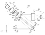
- FIG. 7 is a configuration diagram showing a schematic configuration of a distance measuring device 300 according to Modification 2 of the embodiment. 7, the same or corresponding components as those shown in FIG. 2 or 4 are given the same reference numerals as those shown in FIG.
- the distance measuring device 300 includes a laser light source section 10, a scanning mirror 20, a light receiving optical system 30, a light splitting element 340, a first aperture section 50, and a second aperture section. 60.
- the light splitting element 340 has a reflecting portion 340a and a transmitting portion 340b.
- the reflecting part 340 a reflects the return light L 20 reflected by the scanning mirror 20 and directs it to the light receiving optical system 30 .
- the return light L20 reflected by the scanning mirror 20 is reflected by the light splitting element 40 and enters the light receiving optical system 30 .
- the transmission part 340 b transmits the emitted light L 10 emitted from the irradiation optical system 12 and directs it to the scanning mirror 20 .
- the transmissive portion 340b is, for example, a hole passing through the light splitting element 340.
- the light splitting element 340 is, for example, a perforated mirror.
- the light splitting element 340 may be a reflecting mirror in which a transparent glass is coated with a reflecting film as the reflecting portion 340a. Also, the light splitting element 340 can be realized without having the transmitting portion 340b.
- the emitted light L10 incident on the light splitting element 340 would pass through the inner surface of the hole, which is the transmission section 340b (that is, edge), and scattered light may be generated. Moreover, diffracted light may be generated when the emitted light L10 passes through the hole. Scattered light and diffracted light enter the light receiving optical system 30 as stray light.
- the first aperture section 50 is arranged on the optical path of the emitted light L10 from the laser light source section 10 toward the light splitting element 340 to reduce the diameter of the emitted light L10. This prevents the emitted light L10 from being scattered and diffracted when it enters the light splitting element 340, thereby improving the resolution of the distance measurement direction. Moreover, since the scattered light and the diffracted light are prevented from entering the light receiving optical system 30 as stray light, the measurable distance can be extended. Therefore, even in a configuration in which the emitted light L10 emitted from the laser light source unit 10 passes through the light splitting element 340 and the return light L20 is reflected by the light splitting element 340, the resolution of the ranging direction is improved. It can extend the measurable distance.
- the distance measuring device 300 further has a second aperture section 60 arranged on the optical path from the first aperture section 50 to the light splitting element 340 .
- the second opening 60 a of the second aperture section 60 is larger than the first opening 50 a of the first aperture section 50 .
- the second aperture section 60 can shield the diffracted light of the output light L10 that is generated when passing through the first opening 50a.
- FIG. 8 is a diagram of another example of the first aperture section 351 of the distance measuring device 300 according to Modification 2 of the embodiment, viewed in the Z-axis direction.
- the first aperture portion 351 has a light transmitting portion 350a as a light passing portion, a light shielding portion 350b, and a boundary region 350c as a first boundary region.
- the light transmitting portion 350a allows a portion including the central luminous flux of the emitted light L10 to pass therethrough.
- the shape of the light transmitting portion 350a when viewed in the Z-axis direction is, for example, circular.
- the light shielding portion 350b is arranged outside the light transmitting portion 350a and shields peripheral rays of the emitted light L10.
- the light shielding part 350b is, for example, a metal film deposited on transparent glass.
- the boundary region 351c is arranged between the light transmitting portion 350a and the light shielding portion 350b.
- the boundary area 351c is, for example, annular.
- the transmittance of the emitted light L10 in the boundary region 351c increases as it approaches the light transmitting portion 350a and decreases as it approaches the light blocking portion 350b.
- the transmittance has a gradient. Accordingly, when the emitted light L10 emitted from the laser light source section 10 passes through the light transmission section 350a of the first aperture section 351, scattering and diffraction can be prevented.
- the width of the boundary region 351c is preferably about 5% of the diameter of the light transmitting portion 350a.
- the second aperture section 60 has a second boundary area disposed between the light transmission section and the light shielding section, and the transmittance of the second boundary area increases as it approaches the light transmission section. It may be.
- FIG. 9 is a diagram of still another example of the first aperture section 352 of the distance measuring device 300 according to Modification 2 of the embodiment, viewed in the Z-axis direction.
- the first aperture section 352 has an opening 50a and a light blocking section 352b arranged outside the opening 50a.
- a plurality of convex parts 352d are arranged, the width of which narrows as it approaches the opening 50a.
- the inner surface 352s has a sawtooth shape. Accordingly, when the emitted light L10 emitted from the laser light source section 10 passes through the first aperture section 352, it is possible to prevent scattering and diffraction from occurring on the inner surface 352s surrounding the opening 50a.
- a plurality of protrusions may be arranged on the inner surface surrounding the opening 60a of the second aperture section 60, the width of which becomes narrower as it approaches the opening 60a.
- the distance measuring device 300 is arranged on the optical path of the emitted light L10 from the laser light source unit 10 toward the transmission portion 340b of the light splitting element 340. It has a first aperture portion 50 that reduces the diameter. This prevents the emitted light L10 from being scattered and diffracted when it enters the light splitting element 340, thereby improving the resolution of the distance measurement direction. In addition, scattered light and diffracted light of the emitted light L10 are prevented from entering the light receiving optical system 30 as stray light, so that the measurable distance can be extended. Therefore, in the ranging device 300, the measurable distance can be extended while improving the resolution of the ranging azimuth.
- the first aperture portion 351 has the boundary region 351c arranged between the light transmission portion 350a and the light blocking portion 350b, and the emitted light L10 in the boundary region 351c
- the transmittance of becomes higher as it approaches the light transmitting portion 350a.
- FIG. Therefore, in the distance measuring device 300, it is possible to further improve the resolution of the distance measurement direction and further extend the distance that can be measured.
- the inner surface 352s of the first aperture portion 352 surrounding the opening 50a is provided with a plurality of convex portions 352d that become narrower toward the opening 50a. Accordingly, when the emitted light L10 emitted from the laser light source section 10 passes through the first aperture section 352, it is possible to prevent scattering and diffraction from occurring on the inner surface 352s. Therefore, in the distance measuring device 300, it is possible to further improve the resolution of the distance measurement direction and further extend the distance that can be measured.
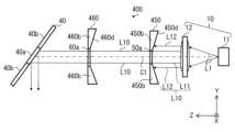
- FIG. 10 is a configuration diagram showing a schematic configuration of distance measuring device 400 according to Modification 3 of the embodiment. 10, the same or corresponding components as those shown in FIG. 5 are given the same reference numerals as those shown in FIG.
- Range finder 400 according to Modification 3 of the embodiment differs from range finder 200 according to Modification 1 of the embodiment in terms of the shapes of first aperture section 450 and second aperture section 460. do.
- rangefinder 400 according to Modification 3 of the embodiment is the same as rangefinder 200 according to Modification 1 of the embodiment. Therefore, FIG. 4 will be referred to in the following description.
- a distance measuring device 400 includes a laser light source unit 10, a scanning mirror 20 (see FIG. 4), a light receiving optical system 30 (see FIG. 4), a light splitting element 40, and a first It has an aperture section 450 and a second aperture section 460 .
- the first aperture part 450 is a plate-like member that becomes thinner as it approaches the first opening 50a. Accordingly, when the emitted light L10 emitted from the laser light source unit 10 passes through the first opening 50a, it is possible to suppress scattering and diffraction on the inner surface surrounding the first opening 50a.
- a surface 450d of the first aperture section 450 on the side of the laser light source section 10 is inclined in a direction away from the laser light source section 10 as it approaches the first opening 50a.
- the second aperture part 460 is a plate-like member that becomes thinner as it approaches the second opening 60a. This can suppress scattering and diffraction on the inner surface surrounding the second opening 60a when the emitted light L10 that has passed through the first opening 50a passes through the second opening 60a.
- a surface 460d of the second aperture section 460 on the first aperture section 450 side is inclined away from the first aperture section 450 as the second opening 60a is approached. At least one of the first aperture portion 450 and the second aperture portion 460 should be thinner as it approaches the opening.
- the first aperture portion 450 is a plate-like member that becomes thinner as it approaches the first opening 50a. Accordingly, when the emitted light L10 emitted from the laser light source unit 10 passes through the first opening 50a, scattering and diffraction on the inner surface surrounding the first opening 50a can be suppressed. Therefore, in the ranging device 400, the measurable distance can be extended while improving the resolution of the ranging azimuth.
- the second aperture portion 460 is a plate-like member that becomes thinner as it approaches the second opening 60a. Accordingly, when the emitted light L10 that has passed through the first opening 50a passes through the second opening 60a, scattering and diffraction on the inner surface surrounding the second opening 60a can be suppressed. Therefore, in the distance measuring device 400, it is possible to further increase the measurable distance while further improving the resolution of the distance measurement direction.
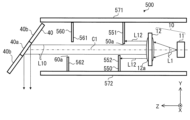
- FIG. 11 is a configuration diagram showing a schematic configuration of a distance measuring device 500 according to Modification 4 of the embodiment. 11, the same or corresponding components as those shown in FIG. 5 are given the same reference numerals as those shown in FIG.
- Range finder 500 according to Modification 4 of the embodiment differs from range finder 200 according to Modification 1 of the embodiment in terms of the shapes of first aperture section 450 and second aperture section 460. do. Except for this point, rangefinder 500 according to Modification 4 of the embodiment is the same as rangefinder 200 according to Modification 1 of the embodiment. Therefore, FIG. 4 will be referred to in the following description.
- a distance measuring device 500 includes a laser light source unit 10, a scanning mirror 20 (see FIG. 4), a light receiving optical system 30 (see FIG. 4), a light splitting element 40, and a first It has an aperture portion 550 , a second aperture portion 560 , a first aperture holding member 571 and a second aperture holding member 572 .
- the first aperture portion 550 has a plate portion 551 as a first plate portion and a plate portion 552 as a second plate portion.
- the plate portion 551 is held by a first aperture holding member 571 .
- the plate portion 552 is held by a second aperture holding member 572 .
- the first aperture holding member 571 and the second aperture holding member 572 may be formed integrally with a member holding another optical member such as the lens or the light splitting element 40 .
- the plate portions 551 and 552 are arranged with the emitted light L10 interposed therebetween. A portion of the emitted light L10 that includes the central luminous flux passes through the opening 50a that is the gap formed between the plate portions 551 and 552 . Further, the peripheral light beam L12 of the emitted light beam L10 that travels away from the optical axis C1 is shielded by the plate portions 551 and 552 . Thereby, the first aperture section 550 can reduce the diameter of the emitted light L10 directed from the laser light source section 10 toward the light splitting element 40 . As a result, the ranging device 500 can extend the measurable distance while improving the resolution of the ranging azimuth.
- the aperture portion is integrated with a member (that is, another holding structure) that holds another optical member such as the lens or the light splitting element 40.
- a member that is, another holding structure
- another optical member such as the lens or the light splitting element 40.
- a method of forming is conceivable.
- the aperture section is integrally formed with another holding structure, the processing becomes difficult, and thus it becomes difficult to form an opening in the aperture section.
- the aperture portion having the opening is a separate part and fixed to the aperture holding member with a screw or the like, the positional accuracy of the aperture portion is deteriorated.
- the portion of the first aperture portion 550 that shields the peripheral ray L12 of the emitted light L10 is divided.
- the plate portion 552 is displaced from the plate portion 551 in the emission direction of the emission light L10 (that is, the Z-axis direction).
- the positional accuracy of the first aperture section 550 can be improved, and stray light can be prevented from occurring.
- formation of the opening 50a in the first aperture portion 550 is facilitated.
- the second aperture portion 560 has a plate portion 561 as a first plate portion and a plate portion 562 as a second plate portion.
- the plate portion 561 is held by a first aperture holding member 571 .
- the plate portion 562 is held by a second aperture holding member 572 .
- the plate portions 561 and 562 are arranged with the emitted light L10 interposed therebetween.
- the emitted light L10 that has passed through the first aperture section 550 passes through the opening 60a that is the gap formed between the plate section 561 and the plate section 562 .
- Opening 60a is larger than opening 50a.
- the plate portions 561 and 562 can shield the diffracted light of the output light L10 generated by passing through the opening 50a.
- the portion of the second aperture portion 560 that shields the diffracted light of the output light L10 is also divided.
- the plate portion 562 is arranged to be displaced from the plate portion 561 in the emission direction of the emission light L10 (that is, the Z-axis direction).
- the positional accuracy of the second aperture portion 560 can be improved, and stray light can be prevented from occurring.
- formation of the opening 60a in the second aperture portion 560 is facilitated.
- FIG. 12 is a view of another example of the first aperture section 550A of the distance measuring device 400 according to Modification 4 of the embodiment, viewed in the Z-axis direction.
- the first aperture portion 550A includes a first plate portion 551A and a second plate portion 552A that is displaced from the first plate portion 551A in the +Z-axis direction. have.
- the second plate portion 552A has a through portion 550e penetrating in the Z-axis direction.
- the first plate portion 551A partially overlaps the penetrating portion 550e.
- part of the penetrating portion 550e is blocked by the first plate portion 551A.
- a portion of the emitted light L10 emitted from the laser light source unit 10 passes through a region of the through portion 550e that is not blocked by the first plate portion 551A.
- the first aperture portion 550A can reduce the diameter of the emitted light L10. Therefore, scattering and diffraction are prevented when the emitted light L10 is incident on the light splitting element 40, that is, stray light is prevented from occurring. You can extend the distance.
- the portion of the first aperture portion 550A that shields the peripheral ray L12 of the emitted light L10 is divided.
- the positional accuracy of the first aperture portion 550A can be improved, and the occurrence of stray light can be prevented.
- the second aperture section 560 may have the same configuration as the first aperture section 550A shown in FIG.
- the first aperture portion 550 includes the plate portion 551 and the plate portion 552 that is displaced from the plate portion 551 in the emission direction of the emitted light L10. , and emitted light L10 directed from the laser light source unit 10 toward the light splitting element 340 passes between the plate portions 551 and 552 .
- the positional accuracy of the first aperture section 550 can be improved, and stray light can be prevented from occurring.
- the second aperture portion 560 has a plate portion 561 and a plate portion 562 that is displaced from the plate portion 561 in the emission direction of the emitted light L10. Then, the emitted light L10 directed from the first aperture portion 550 to the light splitting element 340 passes between the plate portion 561 and the plate portion 562 . As a result, the positional accuracy of the second aperture portion 560 can be improved, and stray light can be prevented from occurring.
- the first aperture portion 550A is arranged to shift from the first plate portion 551A and the first plate portion 551A in the emission direction of the emitted light L10. and a second plate portion 552A.
- the second plate portion 552A has a through portion 550e through which the emitted light L10 passes, and the first plate portion 551A partially overlaps with the through portion 550e when viewed in the emission direction of the emitted light L10.
- Laser light source unit 11 Light source 12 Irradiation optical system 12a Convex lens 20 Scanning mirror 20a Reflecting surface 21, 22 Rotating shaft 30
- Light receiving optical system 31 Condensing optical unit 32
- Light receiving element 40 340 Light splitting Elements 40a, 340a Reflective portions 40b, 340b Transmissive portions 50, 351, 352, 450, 550, 550A First aperture portions 50a, 550a First openings 50b, 350b, 352b
- Distance measuring device 101 Optical scanning device 102 Computer 102a Controller 102b Arithmetic unit 102c Storage device 103 Housing 103a Transparent window 110
- Light transmission optical system 350a Light transmission part 351c Boundary area 352d Convex part 352s Inner surface 450d, 460d Surface 550c, 550e Through part 551, 551A, 552,
Landscapes
- Engineering & Computer Science (AREA)
- Computer Networks & Wireless Communication (AREA)
- Physics & Mathematics (AREA)
- General Physics & Mathematics (AREA)
- Radar, Positioning & Navigation (AREA)
- Remote Sensing (AREA)
- Optical Radar Systems And Details Thereof (AREA)
Abstract
測距装置(100)は、対象物(90)で反射又は散乱した戻り光(L20)を検出して、対象物(90)までの距離を測定する。測距装置(100)は、レーザ光源部(10)と、レーザ光源部(10)から出射された出射光(L10)を走査する走査光学部(20)と、走査光学部(20)で走査された出射光(L10)が照射された対象物(90)で反射し、走査光学部(20)で反射した戻り光(L20)を検出する受光光学部(30)と、レーザ光源部(10)から出射された出射光(L10)を走査光学部(20)に向ける光路案内部(40)と、レーザ光源部(10)から光路案内部(40)に向かう出射光(L10)の光路上に配置され、出射光(L10)の径を小さくする第1のアパーチャ部(50)とを有する。
Description
本開示は、測距装置に関する。
測距装置は、目標領域にレーザ光を照射し、当該目標領域で反射又は散乱した戻り光の有無に基づいて物体の有無を検出する。また、測距装置は、レーザ光の照射タイミングから戻り光の受光タイミングまでの所要時間に基づいて、物体までの距離を検出する。例えば、特許文献1を参照。
特許文献1の装置では、測距可能距離を延ばすために、レーザ光を照射する照射光学系の光軸の一部を、戻り光を受光する受光光学系の光軸の一部と一致させている。また、特許文献1の装置は、レーザ光の光路と戻り光の光路とを分割する光分割素子を有する。特許文献1の光分割素子は、レーザ光を透過させる孔あきミラーである。
しかしながら、特許文献1において、戻り光の受光量を増加させるために、光分割素子の孔を小さくした場合、当該孔を囲う内面(以下、「エッジ」とも呼ぶ。)においてレーザ光が散乱又は回折する。この場合、レーザ光のスポット径が大きくなるため、測距方位の分解能が低下する。また、レーザ光が孔を通過することで形成された散乱光及び回折光が迷光として受光光学系に入射した場合、受光光学系における迷光と戻り光との判別が困難となるため、測距可能距離が縮小する。
本開示は、測距方位の分解能を向上させつつ、測距可能距離を伸ばすことを目的とする。
本開示の一態様に係る光走査装置は、対象物で反射又は散乱した戻り光を検出して、前記対象物までの距離を測定する測距装置であって、レーザ光源部と、前記レーザ光源部から出射された出射光を走査する走査光学部と、前記走査光学部で走査された前記出射光が照射された前記対象物で反射し、前記走査光学部で反射した前記戻り光を検出する受光光学部と、前記レーザ光源部から出射された前記出射光を前記走査光学部に向ける光路案内部と、前記レーザ光源部から前記光路案内部に向かう前記出射光の光路上に配置され、前記出射光の径を小さくする第1のアパーチャ部とを有する、ことを特徴とする。
本開示によれば、測距方位の分解能を向上させつつ、測距可能距離を伸ばすことができる。
以下に、本開示の実施の形態に係る測距装置を、図面を参照しながら説明する。以下の実施の形態は、例にすぎず、実施の形態及び各変形例を適宜組み合わせること及び実施の形態及び各変形例を適宜変更することが可能である。
図面には、説明の理解を容易にするためにXYZ直交座標系の座標軸が示されている。Z軸は、測距装置から対象物に照射される出射光の出射方向に平行な座標軸である。X軸は、Z軸に直交する座標軸である。Y軸は、X軸及びZ軸に直交する座標軸である。
《実施の形態》
〈測距装置100の構成〉
図1は、実施の形態に係る測距装置100の概略的な構成と対象物90とを示す図である。測距装置100は、出射光L10が照射された対象物90で反射又は散乱した戻り光L20を検出して、対象物90までの距離を検出する。測距装置100は、例えば、出射光L10としてシングルモードレーザ光又はマルチモードレーザ光を対象物90に照射する。なお、測距装置100は、複数の対象物90までの距離を検出してもよい。そのため、測距装置100は、少なくとも1つの対象物90までの距離を検出することができる。
〈測距装置100の構成〉
図1は、実施の形態に係る測距装置100の概略的な構成と対象物90とを示す図である。測距装置100は、出射光L10が照射された対象物90で反射又は散乱した戻り光L20を検出して、対象物90までの距離を検出する。測距装置100は、例えば、出射光L10としてシングルモードレーザ光又はマルチモードレーザ光を対象物90に照射する。なお、測距装置100は、複数の対象物90までの距離を検出してもよい。そのため、測距装置100は、少なくとも1つの対象物90までの距離を検出することができる。
測距装置100は、出射光走査装置(以下、「光走査装置」とも呼ぶ。)101と、コンピュータ102と、筐体103とを有する。
〈光走査装置101の構成〉
図2は、図1に示される光走査装置101の概略的な構成を示す構成図である。図2に示されるように、光走査装置101は、レーザ光源部10と、走査光学部としての走査ミラー20と、受光光学部としての受光光学系30と、光路案内部としての光分割素子40とを有する。
図2は、図1に示される光走査装置101の概略的な構成を示す構成図である。図2に示されるように、光走査装置101は、レーザ光源部10と、走査光学部としての走査ミラー20と、受光光学部としての受光光学系30と、光路案内部としての光分割素子40とを有する。
レーザ光源部10は、光源11と、照射光学系12とを有する。以下の説明では、レーザ光源部10の光軸を「光軸C1」と呼ぶ。
光源11は、レーザ光L1を発する。光源11は、例えば、半導体レーザ光源である。光源11の出力は、例えば、10W以上である。
照射光学系12は、光源11から発せられたレーザ光L1をコリメートする。言い換えれば、照射光学系12は、レーザ光L1を平行光に変換して出射光L10として出射する光学部である。照射光学系12は、例えば、凸レンズ12aを有する。ここで、「コリメート」とは、レーザ光L1を平行化することであるが、照射光学系12によって平行化された平行光は広がり角を有しており、当該広がり角は、例えば、0degから2degまでの範囲内である。
実施の形態では、光分割素子40は、出射光L10の光路と戻り光L20の光路とを分離する光学部材である。受光光学系30の光軸を光軸C3としたとき、光分割素子40は、光軸C3に垂直な面に対してX軸回りに回転して傾斜している。図2に示す例では、光分割素子40は、出射光L10を反射させ、且つ戻り光L20を透過させる。具体的には、光分割素子40は、反射部40aと、透過部40bとを有する。
反射部40aは、照射光学系12から出射されて且つ後述するアパーチャ部50を通過した出射光L10を反射して、走査ミラー20に向ける。反射部40aの形状は、例えば、円形である。なお、反射部40aの形状は、円形に限らず、楕円形又は矩形などの他の形状であってもよい。
透過部40bは、走査ミラー20で反射した戻り光L20を透過させて、受光光学系30に向ける。光分割素子40は、例えば、透明ガラスに、反射部40aとしての反射膜がコーティングされることによって形成される。なお、光分割素子40は、透過部40bを有していなくても実現することができる。光分割素子40は、例えば、反射部40aのみを有する微小ミラーであってもよい。この場合、走査ミラー20で反射した戻り光L20は、光分割素子40の外側を通過して受光光学系30に入射する。
走査ミラー20は、光分割素子40で反射した出射光L10を走査する。走査ミラー20は、出射光L10を反射して対象物90(図1参照)に向ける。走査ミラー20は、2つの回転軸21、22周りに回転する。これにより、走査ミラー20は、出射光L10の出射方向を変化させて対象物90に照射する。2つの回転軸21、22は、走査ミラー20の反射面20aの法線に垂直な平面に平行であって且つ互いに垂直である。走査ミラー20は、出射光L10を2次元走査する。走査ミラー20は、例えば、MEMS(Micro Electro Mechanical Systems)ミラーである。走査ミラー20によって走査された出射光L10は、対象物90が位置する光走査領域に照射される。
受光光学系30は、走査ミラー20で反射した戻り光L20を検出する。図2に示す例では、受光光学系30は、集光光学部31と、受光素子32とを有する。
集光光学部31は、光分割素子40を透過した戻り光L20の光路上に配置されている。集光光学部31は、光分割素子40を透過した戻り光L20を集光して、受光素子32に向ける。これにより、受光素子32における戻り光L20の検出精度を向上させることができる。集光光学部31は、例えば、集光レンズを含む。
受光素子32は、戻り光L20を検出する。受光素子32は、例えば、APD(Avalanche Photo Diоde)若しくは単一光子APD等のフォトダイオード又はSiPM(Silicon Photo Multipliers)である。APD、単一光子APD及びSiPMは高い感度を有するため、対象物90(図1参照)が測距装置100から離れた位置にあって且つ当該対象物90における反射率が低い場合であっても、戻り光L20を検出することができる。よって、測距装置100による測距可能距離が増加するため、測距装置100は、より広範囲にわたって対象物90の正確な距離画像を取得することができる。
光走査装置101は、アパーチャ部50(以下、「第1のアパーチャ部50」とも呼ぶ。)を更に有する。
図3は、図2に示される光走査装置101のアパーチャ部50周辺の構成を示す図である。レーザ光源部10、アパーチャ部50及び光分割素子40は、光走査装置101の光送信光学系110を構成する。アパーチャ部50は、レーザ光源部10から光分割素子40に向かう出射光L10の光路上に配置されている。アパーチャ部50は、照射光学系12から出射された出射光L10の径を小さくする。
アパーチャ部50は、第1の光通過部としての開口50a(以下、「第1の開口50a」とも呼ぶ。)を有する。開口50aは、出射光L10の径より小さい。開口50aは、出射光L10のうちの一部の光である中心光束L11を含む部分を通過させる。中心光束L11は、出射光L10のうちの中心光線を含む光束である。また、中心光束L11は、出射光L10のうちの光軸C1上及び光軸C1の近傍の領域を進む光線束である。中心光束L11は、光軸C1の近傍の領域において、光軸C1と平行に進む光線と、光軸C1と非平行に進む光線とを含んでいてもよい。
開口50aは、光分割素子40の反射部40aの径Ahより小さいことが好ましい。開口50aは、例えば、円形である。なお、開口50aは、円形に限らず、楕円形又は矩形などの他の形状であってもよい。
アパーチャ部50は、開口50aより外側に配置された第1の遮光部としての遮光部50bを更に有する。これにより、出射光L10のうち光軸C1から離れた位置を進む周辺光線L12を遮蔽することができる。よって、光分割素子40に入射するときの出射光L10の径を小さくすることができる。
測距装置100にアパーチャ部50が備えられていることによる効果について説明する。上述したように、光分割素子40は、出射光L10を走査ミラー20に向ける反射部40aを有している。測距可能距離を伸ばすためには、反射部40aの領域を狭くする必要がある。言い換えれば、測距可能距離を伸ばすためには、光分割素子40に入射する出射光L10の径(以下、「ビーム径」とも呼ぶ。)を小さくする必要がある。
ここで、出射光L10のビーム径を小さくするために、照射光学系12の凸レンズ12aの焦点距離を短くする方法が考えられる。しかしながら、この方法では、出射光L10の広がり角(すなわち、発散角)が大きくなるため、測定分解能が悪化する。実施の形態に係る測距装置100には、出射光L10の広がり角を抑えつつビーム径を小さくするために、図2及び3に示されるアパーチャ部50が備えられている。
また、実施の形態に係る測距装置100では、光分割素子40は、受光光学系30の視野内に配置されている。言い換えれば、光分割素子40は、走査ミラー20から受光光学系30に向かう戻り光L20の光路上に配置されている。そのため、出射光L10の一部が光分割素子40の反射部40aで反射されなかった場合、受光素子32に入射する迷光が発生する。したがって、仮に、光分割素子40の反射部40aがビーム径を制限するアパーチャ部として用いられた場合、多くの迷光が発生するおそれがある。上述した通り、受光素子32の一例は、APD又はSiPMなどの受光感度の高い素子である。そのため、受光素子32は、数pW程度の微弱な光も検出するため、迷光が発生した場合、測距精度が悪化する。例えば、測距装置100に近い対象物90までの距離を測定する場合に、迷光が発生すると、受光素子32における迷光と戻り光L20との判別が困難となる。そのため、対象物90までの測距可能距離が縮小する。
アパーチャ部50は、光分割素子40に入射するときの出射光L10のビーム径を、レーザ光源部10から出射されたときの出射光L10のビーム径より小さくする。これにより、測距装置100における測距方位の分解能を向上させつつ、測距可能距離を伸ばすことができる。また、実施の形態に係る測距装置100では、照射光学系12のZ軸方向の厚みを厚くせずに、低コスト且つ小型の構成で測距方位の分解能を向上できる。
〈コンピュータ102の構成〉
図1に戻って、コンピュータ102及び筐体103の構成について説明する。コンピュータ102は、制御部としてのコントローラ102aと、演算器102bと、記憶装置102cとを有する。コントローラ102a及び演算器102bは、CPU(Central Proccessing Unit)、GPU(Graphics Proccessing Unit)又はFPGA(Field-Programmable Gate Array)などのプロセッサに備えられている。記憶装置102cは、例えば、ROM(Read On Memory)又はハードディスクである。
図1に戻って、コンピュータ102及び筐体103の構成について説明する。コンピュータ102は、制御部としてのコントローラ102aと、演算器102bと、記憶装置102cとを有する。コントローラ102a及び演算器102bは、CPU(Central Proccessing Unit)、GPU(Graphics Proccessing Unit)又はFPGA(Field-Programmable Gate Array)などのプロセッサに備えられている。記憶装置102cは、例えば、ROM(Read On Memory)又はハードディスクである。
コントローラ102aは、光源11、走査ミラー20及び受光素子32と通信可能に接続されている。コントローラ102aは、光走査装置101を制御する。コントローラ102aによる制御内容については、後述する。
演算器102bは、距離画像を生成する。演算器102bによって生成された距離画像は、測距装置100と対象物90との間の距離と測距装置100から対象物90を見た方向とを含む。演算器102bは、距離画像についての信号を図示しない表示装置に出力する。表示装置は、コンピュータ102(例えば、記憶装置102c)と通信可能に接続されている。表示装置は、距離画像を表示する。
〈筐体103の構成〉
筐体103は、光走査装置101及びコンピュータ102を収容する。筐体103は、透明窓103aを有する。透明窓103aは、光走査装置101から出射された出射光L10及び対象物90で反射又は散乱した戻り光L20を透過させる。なお、透明窓103aは、出射光L10及び戻り光L20のそれぞれの波長と異なる波長を有する波長フィルタによって形成されていてもよい。これにより、不要な光を遮蔽することができる。また、測距装置100において、コンピュータ102は、筐体103に収容されていなくても実現することができる。この場合、コンピュータ102は、筐体103の外部に配置されていてもよい。
筐体103は、光走査装置101及びコンピュータ102を収容する。筐体103は、透明窓103aを有する。透明窓103aは、光走査装置101から出射された出射光L10及び対象物90で反射又は散乱した戻り光L20を透過させる。なお、透明窓103aは、出射光L10及び戻り光L20のそれぞれの波長と異なる波長を有する波長フィルタによって形成されていてもよい。これにより、不要な光を遮蔽することができる。また、測距装置100において、コンピュータ102は、筐体103に収容されていなくても実現することができる。この場合、コンピュータ102は、筐体103の外部に配置されていてもよい。
〈コントローラ102aによる制御〉
次に、図1に示されるコントローラ102aによる制御内容について説明する。コントローラ102aは、光源11を制御する。これにより、レーザ光L1の出射タイミングが制御される。コントローラ102aは、光源11がレーザ光L1を出射した時刻(以下、「第1のタイミング」とも呼ぶ。)を示す信号を、光源11から受信する。
次に、図1に示されるコントローラ102aによる制御内容について説明する。コントローラ102aは、光源11を制御する。これにより、レーザ光L1の出射タイミングが制御される。コントローラ102aは、光源11がレーザ光L1を出射した時刻(以下、「第1のタイミング」とも呼ぶ。)を示す信号を、光源11から受信する。
また、コントローラ102aは、走査ミラー20を制御する。コントローラ102aは、走査ミラー20の傾き角(例えば、走査ミラー20の反射面20aの法線の傾き)を示す信号を、走査ミラー20から受信する。また、コントローラ102aは、受光素子32における戻り光L20の受光量を示す信号を、受光素子32から受信する。また、コントローラ102aは、受光素子32が戻り光L20を検出した時刻(以下、「第2タイミング」とも呼ぶ。)を示す信号も、受光素子32から受信する。
演算器102bは、コントローラ102aが受信した走査ミラー20の傾きと、記憶装置102cに予め格納されている走査ミラー20に対する光源11の位置とに基づいて、出射光L10の出射方向を算出する。
また、演算器102bは、第1タイミングを示す信号及び第2タイミングを示す信号を、コントローラ102aから受信する。演算器102bは、算出した出射光L10の出射方向、第1タイミング及び第2タイミングに基づいて、測距装置100と対象物90との間の距離及び測距装置100に対する対象物90の位置を算出する。
〈実施の形態の効果〉
以上に説明した実施の形態によれば、測距装置100は、レーザ光源部10から光分割素子40の反射部40aに向かう出射光L10の光路上に配置され、出射光L10の径を小さくするアパーチャ部50を有する。これにより、出射光L10が光分割素子40に入射したときの散乱及び回折の発生が防止されるため、測距方位の分解能を向上させることができる。また、出射光L10の散乱光及び回折光が迷光として受光光学系30に入射することが防止されるため、測距可能距離を伸ばすことができる。したがって、実施の形態に係る測距装置100では、測距方位の分解能を向上させつつ、測距可能距離を伸ばすことができる。
以上に説明した実施の形態によれば、測距装置100は、レーザ光源部10から光分割素子40の反射部40aに向かう出射光L10の光路上に配置され、出射光L10の径を小さくするアパーチャ部50を有する。これにより、出射光L10が光分割素子40に入射したときの散乱及び回折の発生が防止されるため、測距方位の分解能を向上させることができる。また、出射光L10の散乱光及び回折光が迷光として受光光学系30に入射することが防止されるため、測距可能距離を伸ばすことができる。したがって、実施の形態に係る測距装置100では、測距方位の分解能を向上させつつ、測距可能距離を伸ばすことができる。
また、実施の形態によれば、アパーチャ部50は、出射光L10の中心光束を含む部分を通過させる開口50aと、開口50aより外側に配置された遮光部50bとを有する。これにより、出射光L10のうち光軸C1から離れた位置を進む周辺光線L12を遮蔽することができる。よって、アパーチャ部50は、光分割素子40に入射するときの出射光L10の径を小さくすることができる。
《実施の形態の変形例1》
図4は、実施の形態の変形例1に係る測距装置200の構成を示す構成図である。図4において、図2に示される構成要素と同一又は対応する構成要素には、図2に示される符号と同じ符号が付される。実施の形態の変形例1に係る測距装置200は、第2のアパーチャ部60を更に有する点で、実施の形態に係る測距装置100と相違する。これ以外の点については、実施の形態の変形例1に係る測距装置200は、実施の形態に係る測距装置100と同じである。
図4は、実施の形態の変形例1に係る測距装置200の構成を示す構成図である。図4において、図2に示される構成要素と同一又は対応する構成要素には、図2に示される符号と同じ符号が付される。実施の形態の変形例1に係る測距装置200は、第2のアパーチャ部60を更に有する点で、実施の形態に係る測距装置100と相違する。これ以外の点については、実施の形態の変形例1に係る測距装置200は、実施の形態に係る測距装置100と同じである。
図4に示されるように、測距装置200は、レーザ光源部10と、走査ミラー20と、受光光学系30と、光分割素子40と、第1のアパーチャ部50と、第2のアパーチャ部60とを有する。
第2のアパーチャ部60は、第1のアパーチャ部50から光分割素子40に向かう出射光L10の光路上に配置されている。
図5は、図4に示される第1のアパーチャ部50及び第2のアパーチャ部60の周辺の構成を示す図である。図4及び5に示されるように、第2のアパーチャ部60は、第2の光通過部としての第2の開口60aと、第2の開口60aより外側に配置された第2の遮光部60bとを有する。
第2の開口60aの開口幅A2は、第1の開口50aの開口幅A1より大きい。ここで、レーザ光源部10から出射された出射光L10のうちの周辺光線L12が第1のアパーチャ部50によって遮光された場合、第1の開口50aを通過した出射光L10の光強度分布は、フレネル回折の影響を受ける。開口幅A2が、開口幅A1より大きいことにより、第1の開口50aを通過したことによって生じた出射光L10の回折光を遮光することができる。
また、開口幅A2は、光分割素子40の反射部40aの径Ah(図3参照)より小さい。第2の開口60aは、例えば、円形である。なお、第2の開口60aは、円形に限らず、楕円形又は上述した矩形などの他の形状であってもよい。
第1のアパーチャ部50及び第2のアパーチャ部60のそれぞれのZ軸方向の厚みは、例えば、2.0mm以下であることが好ましい。これにより、出射光L10が第1の開口50a及び第2の開口60aをそれぞれ通過したときの回折の発生を抑制できる。
また、第1のアパーチャ部50と第2のアパーチャ部60との間の距離は離れている構成が好ましく、第1のアパーチャ部50と第2のアパーチャ部60との間の距離は、1.0mm以上であることが好ましい。図5に示す例では、例えば、第1のアパーチャ部50と第2のアパーチャ部60との間の距離は15mmである。
図6は、出射光L10の光強度分布D1、D2、D3を示すグラフである。図6において、横軸は、光強度を計測した位置[mm]を示し、縦軸は、光強度[a.u.]を示す。
光強度分布D1は、第1の開口50aが3.0mm×3.0mmの矩形形状であって、第1のアパーチャ部50と光分割素子40との間の距離が35mmである場合に、光分割素子40上で計測された出射光L10の光強度分布である。光強度分布D1が計測されるとき、出射光L10の波長は905nmであり、光源11から発せられた出射光L10は照射光学系12によってコリメートされている。上述した実施の形態では、第2のアパーチャ部60が備えられていない。そのため、出射光L10が第1の開口50aを通過したときに発生する回折によって、光強度分布D1は、光分割素子40上の第1の開口50aの外縁に対応する位置(すなわち、±1.5mm)から外側に広がっている。この場合、出射光L10が光分割素子40に入射するときに、反射部40aから漏れることで迷光となる。
光強度分布D2は、第1のアパーチャ部50から+Z軸方向(すなわち、出射光L10の出射方向)に15mm離れた位置における光強度分布である。光強度分布D3は、第2のアパーチャ部60が第1のアパーチャ部50から+Z軸方向に15mm離れた位置に配置され、且つ第2の開口60aが3.1mm×3.1mmの矩形形状である場合に、光分割素子40上で計測された出射光L10の光強度分布である。光強度分布D3では、光分割素子40上の第1の開口50aの外縁に対応する位置(すなわち、±1.5mm)より外側の領域の光強度が、光強度分布D1と比較して小さい。このように、第1の開口50aより大きい第2の開口60aを有する第2のアパーチャ部60が備えられることによって、出射光L10が第1の開口50aを通過したときに発生した回折光が、光分割素子40に迷光として入射することができる。なお、出射光L10の光強度分布がガウス形状などの他の形状であっても、上記と同様の傾向が見られる。
ここで、平面波の出射光L10が開口関数f(x,y)の開口を通過するとき、当該開口から+Z軸方向に距離R離れた位置における振幅分布u(x′,y′)は、以下の式(1)によって示される。
式(1)において、Aは振幅、iは虚数単位、kは波数、(x,y)は開口上での座標、及び(x′,y′)は開口から距離R離れた位置における座標を示す。式(1)の左辺の値が出射光L10のピーク強度の1/5以下となるときの位置に、第2のアパーチャ部60が配置されていることが好ましい。
また、測距装置200をY軸方向に見たときに、第2のアパーチャ部60は、走査ミラー20で反射した戻り光L20と重ならない位置に配置されている。これにより、第2のアパーチャ部60による戻り光L20の遮光を防止することができる。
〈実施の形態の変形例1の効果〉
以上に説明した実施の形態の変形例1によれば、測距装置200は、レーザ光源部10から光分割素子40の反射部40aに向かう出射光L10の光路上に配置され、出射光L10の径を小さくする第1のアパーチャ部50を有する。これにより、出射光L10が光分割素子40に入射したときの散乱及び回折の発生が防止されるため、測距方位の分解能を向上させることができる。また、出射光L10の散乱光及び回折光が迷光として受光光学系30に入射することが防止されるため、測距可能距離を伸ばすことができる。したがって、測距装置200では、測距方位の分解能を向上させつつ、測距可能距離を伸ばすことができる。
以上に説明した実施の形態の変形例1によれば、測距装置200は、レーザ光源部10から光分割素子40の反射部40aに向かう出射光L10の光路上に配置され、出射光L10の径を小さくする第1のアパーチャ部50を有する。これにより、出射光L10が光分割素子40に入射したときの散乱及び回折の発生が防止されるため、測距方位の分解能を向上させることができる。また、出射光L10の散乱光及び回折光が迷光として受光光学系30に入射することが防止されるため、測距可能距離を伸ばすことができる。したがって、測距装置200では、測距方位の分解能を向上させつつ、測距可能距離を伸ばすことができる。
また、実施の形態の変形例1によれば、測距装置200は、第1のアパーチャ部50から光分割素子40に向かう光路上に配置された第2のアパーチャ部60を更に有し、第2のアパーチャ部60の第2の開口60aは、第1のアパーチャ部50の第1の開口50aより大きい。これにより、第1の開口50aを通過したことによって生じた出射光L10の回折光を第2のアパーチャ部60によって遮光することができる。したがって、実施の形態の変形例1に係る測距装置200では、測距方位の分解能を一層向上させつつ、測距可能距離を更に伸ばすことができる。
《実施の形態の変形例2》
上記実施の形態及び実施の形態の変形例1では、レーザ光源部10から出射された出射光L10が光分割素子40で反射して走査ミラー20に向けられ、戻り光L20が光分割素子40を透過して受光光学系30に入射する例を説明した。実施の形態の変形例2では、レーザ光源部10から出射された出射光L10が光分割素子340を通過して走査ミラー20に向けられ、戻り光L20が光分割素子40で反射して受光光学系30に入射する例を説明する。図7は、実施の形態の変形例2に係る測距装置300の概略的な構成を示す構成図である。図7において、図2又は4に示される構成要素と同一又は対応する構成要素には、図2又は4に示される符号と同じ符号が付される。
上記実施の形態及び実施の形態の変形例1では、レーザ光源部10から出射された出射光L10が光分割素子40で反射して走査ミラー20に向けられ、戻り光L20が光分割素子40を透過して受光光学系30に入射する例を説明した。実施の形態の変形例2では、レーザ光源部10から出射された出射光L10が光分割素子340を通過して走査ミラー20に向けられ、戻り光L20が光分割素子40で反射して受光光学系30に入射する例を説明する。図7は、実施の形態の変形例2に係る測距装置300の概略的な構成を示す構成図である。図7において、図2又は4に示される構成要素と同一又は対応する構成要素には、図2又は4に示される符号と同じ符号が付される。
図7に示されるように、測距装置300は、レーザ光源部10と、走査ミラー20と、受光光学系30と、光分割素子340と、第1のアパーチャ部50と、第2のアパーチャ部60とを有する。
光分割素子340は、反射部340aと、透過部340bとを有する。
反射部340aは、走査ミラー20で反射した戻り光L20を反射して受光光学系30に向ける。このように、実施の形態の変形例2では、走査ミラー20で反射した戻り光L20が、光分割素子40で反射して受光光学系30に入射する。
透過部340bは、照射光学系12から出射された出射光L10を透過して走査ミラー20に向ける。透過部340bは、例えば、光分割素子340を貫通する孔である。すなわち、光分割素子340は、例えば、孔あきミラーである。なお、光分割素子340は、透明ガラスに、反射部340aとしての反射膜がコーティングされた反射ミラーであってもよい。また、光分割素子340は、透過部340bを有していなくても実現することができる。
仮に、第1のアパーチャ部50及び第2のアパーチャ部60が測距装置300に備えられていない場合、光分割素子340に入射した出射光L10が、透過部340bである孔の内面(すなわち、エッジ)において散乱して散乱光が発生するおそれがある。また、出射光L10が、当該孔を通過したときに回折光が発生する場合がある。散乱光及び回折光が、迷光として受光光学系30に入射する。
実施の形態の変形例2では、第1のアパーチャ部50が、レーザ光源部10から光分割素子340に向かう出射光L10の光路上に配置され、出射光L10の径を小さくする。これにより、出射光L10が光分割素子340に入射したときの散乱及び回折の発生が防止されるため、測距方位の分解能を向上させることができる。また、当該散乱光及び回折光が迷光として受光光学系30に入射することが防止されるため、測距可能距離を伸ばすことができる。したがって、レーザ光源部10から出射された出射光L10が光分割素子340を通過し、且つ戻り光L20が光分割素子340で反射する構成であっても、測距方位の分解能を向上させつつ、測距可能距離を伸ばすことができる。
また、測距装置300は、第1のアパーチャ部50から光分割素子340に向かう光路上に配置された第2のアパーチャ部60を更に有する。第2のアパーチャ部60の第2の開口60aは、第1のアパーチャ部50の第1の開口50aより大きい。これにより、第2のアパーチャ部60は、第1の開口50aを通過したときに生じた出射光L10の回折光を遮光することができる。
図8は、実施の形態の変形例2に係る測距装置300の第1のアパーチャ部351の他の例をZ軸方向に見た図である。図8に示されるように、第1のアパーチャ部351は、光通過部としての光透過部350aと、遮光部350bと、第1の境界領域としての境界領域350cとを有する。
光透過部350aは、出射光L10の中心光束を含む部分を通過させる。Z軸方向に見たときの光透過部350aの形状は、例えば、円形である。遮光部350bは、光透過部350aより外側に配置され、出射光L10の周辺光線を遮光する。遮光部350bは、例えば、透明ガラスに蒸着された金属膜である。
境界領域351cは、光透過部350aと遮光部350bとの間に配置されている。境界領域351cは、例えば、円環状である。境界領域351cにおける出射光L10の透過率は、光透過部350aに近づくほど高くなり、遮光部350bに近づくほど低くなる。
このように、第1のアパーチャ部351の境界領域351cでは、透過率が勾配を有している。これにより、レーザ光源部10が出射された出射光L10が第1のアパーチャ部351の光透過部350aを通過するときに、散乱及び回折の発生を防止することができる。境界領域351cの幅は、光透過部350aの直径の5%程度であることが好ましい。なお、第2のアパーチャ部60が、光透過部と遮光部との間に配置された第2の境界領域とを有し、当該第2の境界領域の透過率が光透過部に近づくほど高くなっていてもよい。
図9は、実施の形態の変形例2に係る測距装置300の第1のアパーチャ部352の更に他の例をZ軸方向に見た図である。図9に示されるように、第1のアパーチャ部352は、開口50aと、開口50aより外側に配置された遮光部352bとを有する。
第1のアパーチャ部352のうち開口50aを囲う内面352sには、開口50aに近づくほど幅狭となる複数の凸部352dが配置されている。図9に示す例では、内面352sは、鋸波形状である。これにより、レーザ光源部10が出射された出射光L10が第1のアパーチャ部352を通過するときに、開口50aを囲う内面352sでの散乱及び回折の発生を防止することができる。なお、第2のアパーチャ部60の開口60aを囲う内面に、開口60aに近づくほど幅狭となる複数の凸部が配置されていてもよい。
〈実施の形態の変形例2の効果〉
以上に説明した実施の形態の変形例2によれば、測距装置300は、レーザ光源部10から光分割素子340の透過部340bに向かう出射光L10の光路上に配置され、出射光L10の径を小さくする第1のアパーチャ部50を有する。これにより、出射光L10が光分割素子340に入射したときの散乱及び回折の発生が防止されるため、測距方位の分解能を向上させることができる。また、出射光L10の散乱光及び回折光が迷光として受光光学系30に入射することが防止されるため、測距可能距離を伸ばすことができる。したがって、測距装置300では、測距方位の分解能を向上させつつ、測距可能距離を伸ばすことができる。
以上に説明した実施の形態の変形例2によれば、測距装置300は、レーザ光源部10から光分割素子340の透過部340bに向かう出射光L10の光路上に配置され、出射光L10の径を小さくする第1のアパーチャ部50を有する。これにより、出射光L10が光分割素子340に入射したときの散乱及び回折の発生が防止されるため、測距方位の分解能を向上させることができる。また、出射光L10の散乱光及び回折光が迷光として受光光学系30に入射することが防止されるため、測距可能距離を伸ばすことができる。したがって、測距装置300では、測距方位の分解能を向上させつつ、測距可能距離を伸ばすことができる。
また、実施の形態の変形例2によれば、第1のアパーチャ部351は、光透過部350aと遮光部350bとの間に配置された境界領域351cを有し、境界領域351cにおける出射光L10の透過率は、光透過部350aに近づくほど高くなる。これにより、レーザ光源部10が出射された出射光L10が第1のアパーチャ部351の光透過部350aを通過するときの散乱及び回折の発生を防止することができる。よって、測距装置300では、測距方位の分解能を一層向上させつつ、測距可能距離を一層伸ばすことができる。
また、実施の形態の変形例2によれば、第1のアパーチャ部352のうち開口50aを囲う内面352sには、開口50aに近づくほど幅狭となる複数の凸部352dが配置されている。これにより、レーザ光源部10が出射された出射光L10が第1のアパーチャ部352を通過するときに、内面352sでの散乱及び回折の発生を防止することができる。よって、測距装置300では、測距方位の分解能を一層向上させつつ、測距可能距離を一層伸ばすことができる。
《実施の形態の変形例3》
図10は、実施の形態の変形例3に係る測距装置400の概略的な構成を示す構成図である。図10において、図5に示される構成要素と同一又は対応する構成要素には、図5に示される符号と同じ符号が付される。実施の形態の変形例3に係る測距装置400は、第1のアパーチャ部450及び第2のアパーチャ部460それぞれの形状の点で、実施の形態の変形例1に係る測距装置200と相違する。これ以外の点については、実施の形態の変形例3に係る測距装置400は、実施の形態の変形例1に係る測距装置200と同じである。そのため、以下の説明では、図4を参照する。
図10は、実施の形態の変形例3に係る測距装置400の概略的な構成を示す構成図である。図10において、図5に示される構成要素と同一又は対応する構成要素には、図5に示される符号と同じ符号が付される。実施の形態の変形例3に係る測距装置400は、第1のアパーチャ部450及び第2のアパーチャ部460それぞれの形状の点で、実施の形態の変形例1に係る測距装置200と相違する。これ以外の点については、実施の形態の変形例3に係る測距装置400は、実施の形態の変形例1に係る測距装置200と同じである。そのため、以下の説明では、図4を参照する。
図10に示されるように、測距装置400は、レーザ光源部10と、走査ミラー20(図4参照)と、受光光学系30(図4参照)と、光分割素子40と、第1のアパーチャ部450と、第2のアパーチャ部460とを有する。
第1のアパーチャ部450は、第1の開口50aに近づくほど薄肉となる板状の部材である。これにより、レーザ光源部10から出射された出射光L10が第1の開口50aを通過するときに、第1の開口50aを囲う内面において散乱及び回折することを抑制できる。図10に示す例では、第1のアパーチャ部450のレーザ光源部10側の面450dが、第1の開口50aに近づくほどレーザ光源部10から離れる方向に傾斜している。
第2のアパーチャ部460は、第2の開口60aに近づくほど薄肉となる板状の部材である。これにより、第1の開口50aを通過した出射光L10が第2の開口60aを通過するときに、第2の開口60aを囲う内面において散乱及び回折することを抑制できる。図10に示す例では、第2のアパーチャ部460の第1のアパーチャ部450側の面460dが、第2の開口60aに近づくほど第1のアパーチャ部450から離れる方向に傾斜している。なお、第1のアパーチャ部450及び第2のアパーチャ部460のうちの少なくとも一方のアパーチャ部が、開口に近づくほど薄肉となっていればよい。
〈実施の形態の変形例3の効果〉
以上に説明した実施の形態の変形例3によれば、第1のアパーチャ部450は、第1の開口50aに近づくほど薄肉となる板状の部材である。これにより、レーザ光源部10から出射された出射光L10が第1の開口50aを通過するときに、第1の開口50aを囲う内面における散乱及び回折の発生を抑制できる。よって、測距装置400では、測距方位の分解能を向上させつつ、測距可能距離を伸ばすことができる。
以上に説明した実施の形態の変形例3によれば、第1のアパーチャ部450は、第1の開口50aに近づくほど薄肉となる板状の部材である。これにより、レーザ光源部10から出射された出射光L10が第1の開口50aを通過するときに、第1の開口50aを囲う内面における散乱及び回折の発生を抑制できる。よって、測距装置400では、測距方位の分解能を向上させつつ、測距可能距離を伸ばすことができる。
また、実施の形態の変形例3によれば、第2のアパーチャ部460は、第2の開口60aに近づくほど薄肉となる板状の部材である。これにより、第1の開口50aを通過した出射光L10が第2の開口60aを通過するときに、第2の開口60aを囲う内面における散乱及び回折の発生を抑制できる。よって、測距装置400では、測距方位の分解能を一層向上させつつ、測距可能距離を一層伸ばすことができる。
《実施の形態の変形例4》
図11は、実施の形態の変形例4に係る測距装置500の概略的な構成を示す構成図である。図11において、図5に示される構成要素と同一又は対応する構成要素には、図5に示される符号と同じ符号が付される。実施の形態の変形例4に係る測距装置500は、第1のアパーチャ部450及び第2のアパーチャ部460それぞれの形状の点で、実施の形態の変形例1に係る測距装置200と相違する。これ以外の点については、実施の形態の変形例4に係る測距装置500は、実施の形態の変形例1に係る測距装置200と同じである。そのため、以下の説明では、図4を参照する。
図11は、実施の形態の変形例4に係る測距装置500の概略的な構成を示す構成図である。図11において、図5に示される構成要素と同一又は対応する構成要素には、図5に示される符号と同じ符号が付される。実施の形態の変形例4に係る測距装置500は、第1のアパーチャ部450及び第2のアパーチャ部460それぞれの形状の点で、実施の形態の変形例1に係る測距装置200と相違する。これ以外の点については、実施の形態の変形例4に係る測距装置500は、実施の形態の変形例1に係る測距装置200と同じである。そのため、以下の説明では、図4を参照する。
図11に示されるように、測距装置500は、レーザ光源部10と、走査ミラー20(図4参照)と、受光光学系30(図4参照)と、光分割素子40と、第1のアパーチャ部550と、第2のアパーチャ部560と、第1のアパーチャ保持部材571と、第2のアパーチャ保持部材572とを有する。
第1のアパーチャ部550は、第1の板部としての板部551と、第2の板部としての板部552とを有する。板部551は、第1のアパーチャ保持部材571によって保持されている。板部552は、第2のアパーチャ保持部材572によって保持されている。なお、第1のアパーチャ保持部材571及び第2のアパーチャ保持部材572は、レンズ又は光分割素子40などの他の光学部材を保持する部材と一体に形成されていてもよい。
板部551、552は、出射光L10を挟んで配置されている。出射光L10のうち中心光束を含む部分は、板部551と板部552との間に形成された間隙である開口50aを通過する。また、出射光L10のうち光軸C1から離れた位置を進む周辺光線L12は、板部551及び板部552によって遮蔽される。これにより、第1のアパーチャ部550は、レーザ光源部10から光分割素子40に向かう出射光L10の径を小さくできる。これにより、測距装置500は、測距方位の分解能を向上させつつ、測距可能距離を伸ばすことができる。
ここで、アパーチャ部を光軸C1に対して精度良く配置するために、アパーチャ部を、レンズ又は光分割素子40などの他の光学部材を保持する部材(すなわち、他の保持構造)と一体に形成する方法が考えられる。しかしながら、アパーチャ部を他の保持構造と一体に形成する場合、加工が難しくなるため、アパーチャ部における開口の形成が困難となる。また、開口を有するアパーチャ部を別部品として、アパーチャ保持部材にネジなどで固定する場合、アパーチャ部の位置精度が低下する。実施の形態の変形例4では、第1のアパーチャ部550のうち出射光L10の周辺光線L12を遮光する部分は、分割されている。具体的には板部552は、板部551に対して出射光L10の出射方向(すなわち、Z軸方向)にずれて配置されている。これにより、第1のアパーチャ部550の位置精度を高めつつ、迷光の発生を防止することができる。また、実施の形態の変形例4では、第1のアパーチャ部550における開口50aの形成が容易となる。
第2のアパーチャ部560は、第1の板部としての板部561と、第2の板部としての板部562とを有する。板部561は、第1のアパーチャ保持部材571によって保持されている。板部562は、第2のアパーチャ保持部材572によって保持されている。
板部561、562は、出射光L10を挟んで配置されている。第1のアパーチャ部550を通過した出射光L10は、板部561と板部562との間に形成された間隙である開口60aを通過する。開口60aは、開口50aより大きい。これにより、開口50aを通過したことによって生じた出射光L10の回折光を板部561、562によって遮光することができる。
このように、実施の形態の変形例4では、第2のアパーチャ部560のうち出射光L10の回折光を遮光する部分も、分割されている。具体的には、板部562は、板部561に対して出射光L10の出射方向(すなわち、Z軸方向)にずれて配置されている。これにより、第2のアパーチャ部560の位置精度を高めつつ、迷光の発生を防止することができる。また、実施の形態の変形例4では、第2のアパーチャ部560における開口60aの形成が容易となる。
図12は、実施の形態の変形例4に係る測距装置400の第1のアパーチャ部550Aの他の例をZ軸方向に見た図である。図12に示されるように、第1のアパーチャ部550Aは、第1の板部551Aと、第1の板部551Aに対して+Z軸方向にずれて配置された第2の板部552Aとを有する。
第2の板部552Aは、Z軸方向に貫通する貫通部550eを有する。Z軸方向に見たときに第1の板部551Aは、貫通部550eの一部と重なっている。このように、図12に示す例では、貫通部550eの一部は、第1の板部551Aによって遮られている。レーザ光源部10から出射された出射光L10の一部は、貫通部550eのうち第1の板部551Aによって遮られていない領域を通過する。これにより、第1のアパーチャ部550Aは、出射光L10の径を小さくすることができる。よって、出射光L10が光分割素子40に入射したときの散乱及び回折の発生が防止されるため、すなわち、迷光の発生が防止されるため、測距方位の分解能を向上させつつ、測距可能距離を伸ばすことができる。
また、図12に示す例でも、第1のアパーチャ部550Aのうち出射光L10の周辺光線L12を遮光する部分は、分割されている。これにより、第1のアパーチャ部550Aの位置精度を高めつつ、迷光の発生を防止することができる。なお、第2のアパーチャ部560が、図12に示される第1のアパーチャ部550Aと同様の構成であってもよい。
〈実施の形態の変形例4の効果〉
以上に説明した実施の形態の変形例4によれば、第1のアパーチャ部550は、板部551と、板部551に対して出射光L10の出射方向にずれて配置された板部552とを有し、レーザ光源部10から光分割素子340に向かう出射光L10は、板部551と板部552との間を通過する。これにより、第1のアパーチャ部550の位置精度を高めつつ、迷光の発生を防止することができる。
以上に説明した実施の形態の変形例4によれば、第1のアパーチャ部550は、板部551と、板部551に対して出射光L10の出射方向にずれて配置された板部552とを有し、レーザ光源部10から光分割素子340に向かう出射光L10は、板部551と板部552との間を通過する。これにより、第1のアパーチャ部550の位置精度を高めつつ、迷光の発生を防止することができる。
また、実施の形態の変形例4によれば、第2のアパーチャ部560は、板部561と、板部561に対して出射光L10の出射方向にずれて配置された板部562とを有し、第1のアパーチャ部550から光分割素子340に向かう出射光L10は、板部561と板部562との間を通過する。これにより、第2のアパーチャ部560の位置精度を高めつつ、迷光の発生を防止することができる。
また、実施の形態の変形例4によれば、第1のアパーチャ部550Aは、第1の板部551Aと、第1の板部551Aに対して出射光L10の出射方向にずれて配置された第2の板部552Aとを有する。第2の板部552Aは、出射光L10が通過する貫通部550eを有し、出射光L10の出射方向に見たときに第1の板部551Aが貫通部550eの一部と重なっている。これにより、第1のアパーチャ部550Aの位置精度を高めつつ、迷光の発生を防止することができる。
10 レーザ光源部、 11 光源、 12 照射光学系、 12a 凸レンズ、 20 走査ミラー、 20a 反射面、 21、22 回転軸、 30 受光光学系、 31 集光光学部、 32 受光素子、 40、340 光分割素子、 40a、340a 反射部、 40b、340b 透過部、 50、351、352、450、550、550A 第1のアパーチャ部、 50a、550a 第1の開口、 50b、350b、352b 遮光部、 60、460、560 第2のアパーチャ部、 60a、560a 第2の開口、 60b 第2の遮光部、 90 対象物、 100、200、300、400 測距装置、 101 光走査装置、 102 コンピュータ、 102a コントローラ、 102b 演算器、 102c 記憶装置、 103 筐体、 103a 透明窓、 110 光送信光学系、 350a 光透過部、 351c 境界領域、 352d 凸部、 352s 内面、 450d、460d 面、 550c、550e 貫通部、 551、551A、552、552A、561、562 板部、 571 第1のアパーチャ保持部材、 572 第2のアパーチャ保持部材、 A1、A2 開口幅、Ah 径、 C1、C3 光軸、 D1、D2、D3 光強度分布、 L1 レーザ光、 L10 出射光、 L11 中心光束、 L12 周辺光線、 L20 戻り光。
Claims (18)
- 対象物で反射又は散乱した戻り光を検出して、前記対象物までの距離を測定する測距装置であって、
レーザ光源部と、
前記レーザ光源部から出射された出射光を走査する走査光学部と、
前記走査光学部で走査された前記出射光が照射された前記対象物で反射し、前記走査光学部で反射した前記戻り光を検出する受光光学部と、
前記レーザ光源部から出射された前記出射光を前記走査光学部に向ける光路案内部と、
前記レーザ光源部から前記光路案内部に向かう前記出射光の光路上に配置され、前記出射光の径を小さくする第1のアパーチャ部と
を有する、
ことを特徴とする測距装置。 - 前記走査光学部で反射した前記戻り光は、前記光路案内部を透過して前記受光光学部に入射する、
ことを特徴とする請求項1に記載の測距装置。 - 前記走査光学部で反射した前記戻り光は、前記光路案内部で反射して前記受光光学部に入射する、
ことを特徴とする請求項1に記載の測距装置。 - 前記走査光学部で反射した前記戻り光は、前記光路案内部の外側を通過して前記受光光学部に入射する、
ことを特徴とする請求項1に記載の測距装置。 - 前記第1のアパーチャ部は、
前記出射光の中心光束を含む部分を通過させる第1の光通過部と、
前記第1の光通過部の外側に配置された第1の遮光部と
を有する、
ことを特徴とする請求項1から4のいずれか1項に記載の測距装置。 - 前記第1のアパーチャ部は、前記第1の光通過部と前記第1の遮光部との間に配置された第1の境界領域を更に有し、
前記第1の境界領域における前記出射光の透過率は、前記第1の光通過部に近づくほど高くなる、
ことを特徴とする請求項5に記載の測距装置。 - 前記第1の光通過部は、前記出射光の径より小さい第1の開口である、
ことを特徴とする請求項5に記載の測距装置。 - 前記第1のアパーチャ部から前記光路案内部に向かう前記出射光の光路上に配置され、前記第1の光通過部より大きい第2の光通過部を含む第2のアパーチャ部を更に有する、
ことを特徴とする請求項7に記載の測距装置。 - 前記第2の光通過部は、前記第1の開口より大きい第2の開口である、
ことを特徴とする請求項8に記載の測距装置。 - 前記第1の開口及び前記第2の開口の少なくとも一方である開口を囲う内面には、前記開口に近づくほど幅狭となる複数の凸部が配列されている、
ことを特徴とする請求項9に記載の測距装置。 - 前記第1のアパーチャ部と前記第2のアパーチャ部との間の距離は、1.0mm以上である、
ことを特徴とする請求項8から10のいずれか1項に記載の測距装置。 - 前記第1のアパーチャ部及び前記第2のアパーチャ部のうちの少なくとも一方の前記出射光の出射方向の厚みは、2.0mm以上である、
ことを特徴とする請求項8から11のいずれか1項に記載の測距装置。 - 前記第2のアパーチャ部は、
前記第2の光通過部の外側に配置された第2の遮光部と
前記第2の光通過部と前記第2の遮光部との間に配置された第2の境界領域と
を更に含み、
前記第2の境界領域における前記出射光の通過率は、前記第2の光通過部に近づくほど高くなる、
ことを特徴とする請求項8から12のいずれか1項に記載の測距装置。 - 前記第1のアパーチャ部及び前記第2のアパーチャ部のうちの少なくとも一方は、前記第1の光通過部に近づくほど薄肉となる板状の部材である、
ことを特徴とする請求項8から13のいずれか1項に記載の測距装置。 - 前記第1のアパーチャ部及び前記第2のアパーチャ部のうちの少なくとも一方は、
第1の板部と、
前記第1の板部に対して前記出射光の出射方向にずれて配置された第2の板部と
を有し、
前記レーザ光源部から前記光路案内部に向かう前記出射光は、前記第1の板部と前記第2の板部との間を通過する、
ことを特徴とする請求項8から14のいずれか1項に記載の測距装置。 - 前記第1のアパーチャ部及び前記第2のアパーチャ部のうちの少なくとも一方は、
第1の板部と、
前記第1の板部に対して前記出射光の出射方向にずれて配置された第2の板部と
を有し、
前記第2の板部は、前記レーザ光源部から前記光路案内部に向かう前記出射光が通過する貫通部を有し、
前記出射方向に見たときに、前記第1の板部は、前記貫通部の一部と重なっている、
ことを特徴とする請求項8から14のいずれか1項に記載の測距装置。 - 前記レーザ光源部は、
光源と、
前記光源から発せられたレーザ光を平行光に変換して前記出射光として出射する光学部と
を有する、
ことを特徴とする請求項1から16のいずれか1項に記載の測距装置。 - 前記受光光学部は、
受光素子と、
前記走査光学部で反射した前記戻り光を集光して前記受光素子に向ける集光レンズと
を有し、
前記光路案内部は、前記受光光学部の光軸に垂直な面に対して傾斜している、
ことを特徴とする請求項1から17のいずれか1項に記載の測距装置。
Priority Applications (2)
| Application Number | Priority Date | Filing Date | Title |
|---|---|---|---|
| PCT/JP2021/028256 WO2023007694A1 (ja) | 2021-07-30 | 2021-07-30 | 測距装置 |
| JP2022553198A JP7311718B2 (ja) | 2021-07-30 | 2021-07-30 | 測距装置 |
Applications Claiming Priority (1)
| Application Number | Priority Date | Filing Date | Title |
|---|---|---|---|
| PCT/JP2021/028256 WO2023007694A1 (ja) | 2021-07-30 | 2021-07-30 | 測距装置 |
Publications (1)
| Publication Number | Publication Date |
|---|---|
| WO2023007694A1 true WO2023007694A1 (ja) | 2023-02-02 |
Family
ID=85086581
Family Applications (1)
| Application Number | Title | Priority Date | Filing Date |
|---|---|---|---|
| PCT/JP2021/028256 WO2023007694A1 (ja) | 2021-07-30 | 2021-07-30 | 測距装置 |
Country Status (2)
| Country | Link |
|---|---|
| JP (1) | JP7311718B2 (ja) |
| WO (1) | WO2023007694A1 (ja) |
Citations (7)
| Publication number | Priority date | Publication date | Assignee | Title |
|---|---|---|---|---|
| JPH0519206A (ja) * | 1990-10-26 | 1993-01-29 | Toyo Ink Mfg Co Ltd | 光ビームのサイズ制御方法 |
| JP2003139534A (ja) * | 2001-10-30 | 2003-05-14 | Pentax Corp | 光波測距儀 |
| JP2004170965A (ja) * | 2002-11-07 | 2004-06-17 | Fuji Photo Optical Co Ltd | 集光光学系 |
| JP2013254661A (ja) * | 2012-06-07 | 2013-12-19 | Omron Corp | 光電センサ |
| JP2014519697A (ja) * | 2011-04-15 | 2014-08-14 | オスラム オプト セミコンダクターズ ゲゼルシャフト ミット ベシュレンクテル ハフツング | 光電子装置 |
| JP2019518204A (ja) * | 2016-12-31 | 2019-06-27 | イノビュージョン アイルランド リミテッドInnovusion Ireland Limited | 回転凹面鏡及びビームステアリング装置の組み合わせを用いた、2d走査型高精度ライダー |
| US20190377068A1 (en) * | 2018-06-10 | 2019-12-12 | Apple Inc. | Patterned mirror edge for stray beam and interference mitigation |
Family Cites Families (3)
| Publication number | Priority date | Publication date | Assignee | Title |
|---|---|---|---|---|
| JP5101955B2 (ja) * | 2006-09-20 | 2012-12-19 | 株式会社ミツトヨ | 形状測定方法及び形状測定装置 |
| JP2015022158A (ja) * | 2013-07-19 | 2015-02-02 | 株式会社リコー | 光走査装置および画像表示装置 |
| JP6363396B2 (ja) | 2014-05-23 | 2018-07-25 | スカラ株式会社 | 光ポインタ |
-
2021
- 2021-07-30 WO PCT/JP2021/028256 patent/WO2023007694A1/ja unknown
- 2021-07-30 JP JP2022553198A patent/JP7311718B2/ja active Active
Patent Citations (7)
| Publication number | Priority date | Publication date | Assignee | Title |
|---|---|---|---|---|
| JPH0519206A (ja) * | 1990-10-26 | 1993-01-29 | Toyo Ink Mfg Co Ltd | 光ビームのサイズ制御方法 |
| JP2003139534A (ja) * | 2001-10-30 | 2003-05-14 | Pentax Corp | 光波測距儀 |
| JP2004170965A (ja) * | 2002-11-07 | 2004-06-17 | Fuji Photo Optical Co Ltd | 集光光学系 |
| JP2014519697A (ja) * | 2011-04-15 | 2014-08-14 | オスラム オプト セミコンダクターズ ゲゼルシャフト ミット ベシュレンクテル ハフツング | 光電子装置 |
| JP2013254661A (ja) * | 2012-06-07 | 2013-12-19 | Omron Corp | 光電センサ |
| JP2019518204A (ja) * | 2016-12-31 | 2019-06-27 | イノビュージョン アイルランド リミテッドInnovusion Ireland Limited | 回転凹面鏡及びビームステアリング装置の組み合わせを用いた、2d走査型高精度ライダー |
| US20190377068A1 (en) * | 2018-06-10 | 2019-12-12 | Apple Inc. | Patterned mirror edge for stray beam and interference mitigation |
Also Published As
| Publication number | Publication date |
|---|---|
| JP7311718B2 (ja) | 2023-07-19 |
| JPWO2023007694A1 (ja) | 2023-02-02 |
Similar Documents
| Publication | Publication Date | Title |
|---|---|---|
| US11041753B2 (en) | Light detection using an aperture | |
| JP2004521355A (ja) | 光学的距離測定装置 | |
| EP2339366B1 (en) | Optical distance measuring device | |
| US11852852B2 (en) | Patterned mirror edge for stray beam and interference mitigation | |
| JP2017110964A (ja) | 光波距離測定装置 | |
| JP5452245B2 (ja) | 光波距離測定装置 | |
| JP2007514942A (ja) | 遠方・近接物体との距離測定装置 | |
| WO2023007694A1 (ja) | 測距装置 | |
| EP3332277B1 (en) | Backscatter reductant anamorphic beam sampler | |
| JP2006053055A (ja) | レーザ測定装置 | |
| US5815272A (en) | Filter for laser gaging system | |
| JP7170251B2 (ja) | 距離測定装置 | |
| JP2001021480A (ja) | フローセル及びこのフローセルを用いた粒子測定装置 | |
| JPH10246616A (ja) | 多心テープ光ファイバの表面状態観測方法、表面異状検出方法および表面状態測定装置 | |
| KR100749829B1 (ko) | 3차원 광측정장치 | |
| WO2018173294A1 (ja) | 計測装置 | |
| JP2019023650A (ja) | 光波距離測定装置 | |
| JPH07146115A (ja) | 光センサ | |
| US11372109B1 (en) | Lidar with non-circular spatial filtering | |
| JP2595315B2 (ja) | 光散乱式計測装置 | |
| JP2010164354A (ja) | オートコリメータ | |
| JPWO2023007694A5 (ja) | ||
| JPH10142489A (ja) | 焦点検出方法およびその装置 | |
| JPS6244649A (ja) | 粒子解析装置 | |
| JP2004198244A (ja) | 透過率測定装置および絶対反射率測定装置 |
Legal Events
| Date | Code | Title | Description |
|---|---|---|---|
| ENP | Entry into the national phase |
Ref document number: 2022553198 Country of ref document: JP Kind code of ref document: A |
|
| 121 | Ep: the epo has been informed by wipo that ep was designated in this application |
Ref document number: 21951894 Country of ref document: EP Kind code of ref document: A1 |