WO2022270125A1 - 玩具 - Google Patents
玩具 Download PDFInfo
- Publication number
- WO2022270125A1 WO2022270125A1 PCT/JP2022/017211 JP2022017211W WO2022270125A1 WO 2022270125 A1 WO2022270125 A1 WO 2022270125A1 JP 2022017211 W JP2022017211 W JP 2022017211W WO 2022270125 A1 WO2022270125 A1 WO 2022270125A1
- Authority
- WO
- WIPO (PCT)
- Prior art keywords
- outer shell
- toy
- shell component
- component
- toy according
- Prior art date
- Legal status (The legal status is an assumption and is not a legal conclusion. Google has not performed a legal analysis and makes no representation as to the accuracy of the status listed.)
- Ceased
Links
Images


Classifications
-
- A—HUMAN NECESSITIES
- A63—SPORTS; GAMES; AMUSEMENTS
- A63H—TOYS, e.g. TOPS, DOLLS, HOOPS OR BUILDING BLOCKS
- A63H33/00—Other toys
- A63H33/003—Convertible toys, e.g. robots convertible into rockets or vehicles convertible into planes
-
- A—HUMAN NECESSITIES
- A63—SPORTS; GAMES; AMUSEMENTS
- A63H—TOYS, e.g. TOPS, DOLLS, HOOPS OR BUILDING BLOCKS
- A63H3/00—Dolls
-
- A—HUMAN NECESSITIES
- A63—SPORTS; GAMES; AMUSEMENTS
- A63H—TOYS, e.g. TOPS, DOLLS, HOOPS OR BUILDING BLOCKS
- A63H3/00—Dolls
- A63H3/36—Details; Accessories
- A63H3/50—Frames, stands, or wheels for dolls or toy animals
-
- A—HUMAN NECESSITIES
- A63—SPORTS; GAMES; AMUSEMENTS
- A63H—TOYS, e.g. TOPS, DOLLS, HOOPS OR BUILDING BLOCKS
- A63H33/00—Other toys
-
- G—PHYSICS
- G07—CHECKING-DEVICES
- G07F—COIN-FREED OR LIKE APPARATUS
- G07F11/00—Coin-freed apparatus for dispensing, or the like, discrete articles
Definitions
- the present invention relates to toys.
- capsule toys that store dolls inside capsules and are sold through vending machines.
- parts for assembling a toy are housed inside a capsule composed of capsule constituent members.
- a predetermined number of notches are provided in the cut end of the capsule component, and part or all of the parts can be fitted into the notches to form a toy.
- a configuration is disclosed in which a predetermined number of ribs are provided on the inner wall of the capsule constituent member for holding the cut end of the capsule constituent member.
- Patent Document 1 describes a structure in which the capsule itself is used as a part of a toy.
- the shape of the toy depends on the spherical shape of the capsule, because the shape of the capsule is spherical at the time of sale. For this reason, it becomes difficult to maintain the image of the original character, and depending on the character, the shape of the capsule changes greatly depending on the character, which causes quality problems of the character itself and poses a problem that the interest cannot be maintained.
- the overall shape of the toy itself is basically spherical, there is a problem that the toy is placed and displayed in an unstable state and lacks a sense of stability.
- An object of the present invention is to provide a highly interesting toy that can enhance the image of the character in the display form, is easy to display, has a sense of stability, and is highly interesting.
- a toy according to the present invention is a toy that can be changed between a first form that can be supplied from an article supply device and a second form that can display an object, and comprises a spherical main part,
- the main component has a first plane portion formed at a first portion of the outer surface thereof, and a second plane portion formed at a second portion different from the first portion.
- FIG. 2 is a perspective view showing a mounting structure of the first subcomponent shown in FIG. 1; It is a perspective view which shows the inner surface of a 1st subcomponent. 2 is a perspective view showing a mounting structure of the second sub-part shown in FIG. 1; FIG. FIG. 2 is an exploded perspective view showing a state in which the main parts shown in FIG. 1 are disassembled; FIG. 11 is a perspective view showing the incorporation of the figure in display form; FIG.
- FIG. 11 is a perspective view showing the installation of the third sub-part in display configuration; It is a perspective view which shows an example of the 2nd form of a toy.
- FIG. 11 is a perspective view showing another example of the second form of the toy; It is a perspective view which shows an example of the 3rd form of a toy.
- FIG. 11 is a perspective view showing another example of the third form of the toy; It is an expansion perspective view which shows the formation form of a pattern.
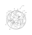
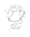
- FIG. 1 is a front view of the first form 1F of the toy 1.
- FIG. FIG. 2 is a top perspective view of the toy 1 in the first form 1F shown in FIG.
- the toy 1 of the first form 1F includes a first outer shell part 11 and a second outer shell part 12 as main parts 10, and has a substantially spherical appearance.
- a first subcomponent 31 is provided on the upper portion and a second subcomponent 32 is provided on the lower portion.
- the outer surface 10s of the toy 1 is composed of the first outer shell part 11, the second outer shell part 12, the first sub-part 31, and the second sub-part 32, and the wrapping film is wrapped around the outer surface 10s. 80 is provided.
- the toy 1 is not supplied (sold) at a store, but is made into a form that can be supplied from an article supply device by making the toy itself easily rollable in the spherical shape in the first form 1F.
- the article supply device includes a storage section that can store a plurality of toys 1 in random arrangement, a control section that controls so that the toys 1 can be supplied one by one from the storage section on the condition that a price is paid, and a supply port from the storage section to the supply port. and a passageway communicating with. Since the toy 1 is composed of a plurality of parts, it is easy to separate. , can be supplied to the user.
- a pattern 10m is formed on the outer surface 10s, and a space SP is formed inside to accommodate a character C or the like, which is an object to be described later. Then, the contents of the toy 1 are taken out by peeling off the wrapping film 80 and disassembled, and the toy 1 is assembled using the character C and the like, and is displayed in a second form 2F (see FIG. 9) and a third form 3F. (see FIG. 11).
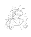
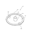
- FIG. 3 is a perspective view showing the mounting structure of the first subpart 31, and FIG. 4 is a perspective view showing the inner surface of the first subpart 31.
- a first flat portion 10f is formed at a first portion of the upper portion of the main component 10, and a substantially disk-shaped first sub-component 31 is provided on the first flat portion 10f.
- the first plane portion 10f is divided by a joining line 10c between the first outer shell component 11 and the second outer shell component 12.
- the first planar portion 10f is a plane divided by a first proportionally divided portion 11f formed on the first outer shell component 11 side and a second proportionally divided portion 12f formed on the second outer shell component 12 side. is.
- the first outer shell component 11 is configured to be larger than the second outer shell component 12, and the size (area) of the first proportionally divided portion 11f is also configured to be larger than the size (area) of the second proportionally divided portion 12f. It is A pair of columnar first connecting portions 11c is provided at a position close to the joining line 10c on the side of the first proportional division portion 11f.
- the outer surface 31s of the first sub-part 31 is formed into a curved surface forming part of a spherical surface (outer surface 10s), and a pattern 10m is formed.
- a pair of mounting notches 31b are provided on the outer peripheral edge of the first sub-part 31, and an insertion hole 31c is formed in the center for mounting a third sub-part 33 (see FIG. 8), which will be described later. ing.
- the inner surface 31i of the first sub-part 31 is configured to correspond to the first flat portion 10f, as shown in FIG. That is, unlike the curved surface of the inner surface 31i, a flat annular flat portion 31e having a predetermined width is formed on the outer peripheral edge of the inner surface. is projected at the same height as the annular flat portion 31e. Therefore, in the first form 1F, the first subpart 31 has the annular flat portion 31e and the boss portion 31a in contact with the first flat portion 10f, and the pair of mounting notches 31b are fitted to the pair of first connecting portions 11c. and connected so as to cover the first plane portion 10f.
- FIG. 5 is a perspective view showing the mounting structure of the second sub-component 32.
- a second flat portion 20f is formed at a second portion of the lower portion of the main component 10, and a second sub-component 32 is provided on the second flat portion 20f.
- the second plane portion 20f is also divided by the joining line 10c between the first outer shell component 11 and the second outer shell component 12.
- the second plane portion 20f is a plane divided by a third proportionally divided portion 23f formed on the first outer shell component 11 side and a fourth proportionally divided portion 24f formed on the second outer shell component 12 side. It has become.
- the second plane portion 20f is configured to have the same size as the first plane portion 10f.
- the size (area) of the third proportional division portion 23f is configured to be larger than the size of the fourth proportional division portion 24f.
- the second subpart 32 has an outer surface 32s (outer surface 10s) that is curved to form a part of a spherical surface, and an inner surface that is similar to the annular flat portion 31e of the first subpart 31. It has a flat portion and a shape corresponding to the second flat portion 20f. Also, the outer peripheral edge of the second sub-part 32 is provided with three mounting notches 32b. Two of the three mounting notches 32b are engaged with the protrusions 22cb of the pair of second connecting portions 22c, and the remaining one is a mounting hole formed with a mounting hole 32c for mounting the character C. engages with the projection 32cb.
- the second subpart 32 is locked by three engagements to cover the second flat portion 20f.
- the pattern 10m is not formed.
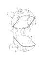
- FIG. 6 is an exploded perspective view showing the disassembled state of the main component 10.
- the main component 10 is composed of the first outer shell component 11 and the second outer shell component 12 as described above. As shown, both are configured, for example, generally hemispherical.
- the opening edges 11e and 12e forming the openings 11o and 12o of both outer shell parts 11 and 12 are configured to be connectable so as to form a spherical space SP inside.
- the opening edge 11e of the first outer shell component 11 is formed with, for example, an inner stepped portion 11ed configured to be thin so that the inner side of the opening edge is recessed.
- the opening edge 12e of the second outer shell component 12 is formed with a thin outer stepped portion 12ed that is recessed on the outside of the opening edge.
- the first outer shell part 11 and the second outer shell part 12 have different swellings (depths) as hemispheres, and the first outer shell part 11 is larger than the second outer shell part 12 in size. ing.
- a pair of cylindrical first connecting portions 11c formed in the first proportionally divided portion 11f are configured to have a size that can be fitted into the second connecting portion 22c of the circular through hole provided in the third proportionally divided portion 23f. Also, the interval between the pair of first connecting portions 11c is configured to be the same as the interval between the second connecting portions 22c. Therefore, the first connecting portion 11c of one first outer shell component 11 and the second connecting portion 22c of another first outer shell component 11 can be fitted and connected. Thereby, it is possible to connect a plurality of the first outer shell parts 11, and it is possible to assemble the display form of the third form 3F different from the single second form 2F.
- the first outer shell part 11 and the second outer shell part 12 are made of synthetic resin, for example, and have appropriate rigidity.
- the pattern 10m drawn on the outer surface 10s is appropriately related to the character C.
- the colors of both outer shell parts 11 and 12 are not particularly limited, they can be made of, for example, a light-transmitting material.
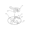
- FIG. 7 is a perspective view showing how the character C is incorporated in the display form.
- FIG. 8 is a perspective view showing the installation of the third subpart 33 in the display configuration.
- the character C is provided with a holding bar 41 extending downward (in the same direction as the legs) on the rear side of the body, for example.
- the proportionally divided flat portion 23a on the inner surface side of the third proportionally divided portion 23f of the first outer shell component 11 has a width that allows the character C to be placed thereon, and furthermore, a mounting hole into which the holding rod 41 can be inserted and fitted. 32c is provided.
- the character C is held on the proportionally divided flat portion 23a.
- the portion where the mounting hole 32c is formed is provided with a mounting hole projection 32cb that protrudes toward the third proportionally divided portion 23f (lower side in the drawing), so that the insertion margin of the holding rod 41 is secured. It is
- the third subcomponent 33 has a shape that imitates the stem of a fruit, for example, and the shaft portion 33a connected to the main body of the fruit is inserted into the insertion hole 31c of the first subcomponent 31, for example. Then, in the display state where the main part 10 is displayed in a shape imitating the fruit of a plant (see FIG. 9), the upper part is decorated.
- the cross-sectional shape of the tip portion (the portion to be fitted) of the shaft portion 33a is configured to be circular, and the mounting direction thereof can be oriented in an appropriate direction. good.
- the third sub-component 33 can be attached to the first sub-component 31. It is not possible and is accommodated within the space SP.
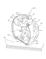
- FIG. 9 is a perspective view showing an example of the second form 2F.
- the display form shown in FIG. 9 is a case where the character C is displayed using the first outer shell part 11, the first sub-part 31, and the third sub-part 33.
- the first subpart 31 is attached and fixed to the first connecting portion 11c of the first outer shell part 11 as in the case of the first form 1F.
- the first outer shell component 11 is stably placed on the mounting surface 60 by providing three protrusions (a pair of protrusions 22cb and a mounting hole protrusion 32cb) on the back side in FIG. be placed.
- no pattern is formed on the inner surface of the first outer shell component 11.
- the first outer shell component 11 is formed of a light-transmitting material, it can be displayed. In this state, the pattern 10m provided on the outer surface 10s can be seen from the inner surface side through light transmission.
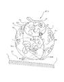
- FIG. 10 is a perspective view showing another example of the second form 2F.
- the display form shown in FIG. 10 uses a first shell part 11, a second shell part 12, a first sub-part 31, and a third sub-part 33, and a character C in a closed sphere. is displayed.
- the character C is fixed in the same manner as in FIG. 9, and furthermore, all but the second sub-part 32 are used to form a substantially spherical fruit.
- the placement surface of the character C is a large flat portion 20a (corresponding to the second flat portion 20f) obtained by combining the proportionally divided flat portion 23a of the first outer shell component 11 and the proportionally divided flat portion 24a of the second outer shell component 12. flat portion on the inner surface side). Therefore, other larger characters C can also be displayed.
- the second outer shell part 12 is configured to have good light transmittance, it is effective to present the character C in the pattern 10m drawn on the outer surface 10s in the exhibition state. made to
- FIG. 11 is a perspective view showing an example of the third form 3F.
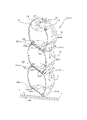
- the case shown in FIG. 11 is the first display state of the third form 3F in which three first outer shell parts 11 are vertically connected.
- the first proportional division part 23f of one first outer shell part 11 is divided into the first proportional division part 23f of the other first outer shell part 11.
- the portions 11f are connected in a one-to-one facing position. Specifically, the pair of first connecting portions 11c of the lower first outer shell component 11 and the pair of second connecting portions 22c of the upper first outer shell component 11 are fitted.
- the mounting hole projection 32cb of the first outer shell component 11 on the upper side is in contact with the first proportionally divided portion 11f of the first outer shell component 11 on the lower side.
- the proportionally divided portion 11f and the third proportionally divided portion 23f of the first outer shell component 11 on the upper side are vertically connected in a straight line with a gap as shown in the drawing.
- the first sub-component 31 incorporating the third sub-component 33 can be attached only to the first proportional division portion 11f located at the uppermost position. In this display form, an elongated and tall display form is produced.
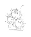
- FIG. 12 is a perspective view showing another example of the third form 3F.
- the display form in the case shown in FIG. 12, two first outer shell parts 11 are connected in a pyramid-shaped (or triangular) arrangement in which one first outer shell part 11 is placed on top of the first outer shell part 11 .
- This is the second display state.
- the first proportionally divided portions 11f of the two lower first outer shell parts 11 correspond to the third proportionally divided parts 23f of one upper first outer shell part 11 in a one-to-two relationship.
- a second display state of the connected third form 3F That is, in this second display state, each of the first connecting portions 11c of the two lower first outer shell components 11 is fitted to the second connecting portion 22c of the upper first outer shell component 11.
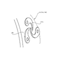
- FIG. 13 is an enlarged perspective view showing a form of pattern formation.
- the pattern 10m formed on the outer surface 10s of the first outer shell component 11, the second outer shell component 12, and the first subcomponent 31 may be a pattern drawn by printing. As shown, the entire pattern 10m can be formed in a projecting shape so as to be raised from the outer surface 10s. Further, unlike this projecting shape, it is also possible to form a recessed shape that is recessed from the outer surface 10s, or a groove shape in which the outline of the pattern 10m is drawn using linear grooves.
- the surface unevenness or The pattern 10m can be varied by utilizing the light transmittance depending on the thickness and the light refraction.
- the pattern 10m is formed only on the outer surface 10s, it is not a pattern drawn directly on the wall surface behind the character C, but an indirect pattern using the thickness of the wall surface and the refraction of light (especially when the transparency is high).
- a delicate pattern production is possible by cooperating with a simple production and a color pattern.
- the pattern 10m is formed only on the outer surface 10s in the drawing, it may be formed on the inner surface side.
- the main part 10 has a spherical appearance and can form the space SP inside. It can be accommodated, and it is possible to display Character C inside in the second form.
- the first form 1f since the toy itself can roll, automatic vending is possible with a vending machine such as an article supply device.
- the main component 10 is composed of a substantially hemispherical first outer shell component 11 and a second outer shell component 12, and the opening edges 11e and 12e of the openings 11o and 12o are configured to be connectable to each other. Therefore, each form change is easy, and the character C can be easily put in and taken out.
- the main component 10 having a spherical shape has the first flat portion 10f and the second flat portion 20f formed as flat portions on the outer surface 10s. 10 can be stably placed on the mounting surface when it is used in the display mode (second mode 2F or third mode 3F). Further, the flat portion 20a on the inner surface side of the second flat portion 20f or the proportionally divided flat portion 23a on the inner surface side of the third proportionally divided portion 23f can be formed, so that the character C can be easily placed and displayed. .
- connection structure (unevenness, holes, etc.), but also to stabilize and maintain the connection state by connecting the flat surfaces facing each other. can be done.
- the first sub-part 31 is connected to the main part 10 via the first connection portion 11c, and the second sub-part 32 is connected to the second connection. Since both sub-parts 31 and 32 are connected through the portion 22c, they can be securely engaged and fixed unlike the case where they are simply placed on a flat portion, and the main part 10 and the main part 10 can be held together without the wrapping film 80 attached. It can maintain its shape.
- the first sub-part 31 to which the third sub-part 33 is attached can be connected to at least the first connecting portion 11c at the uppermost position, so that the decorative parts in the display state securely fixed as
- the size of the first plane portion 10f is the same as that of the second plane portion 20f, and both plane portions 10f and 20f are formed vertically (180 degrees opposite sides).
- the shape balance of the top and bottom is stable and a comfortable exhibition can be produced.
- the size of the first outer shell component 11 is larger than the size of the second outer shell component 2. Therefore, when the first outer shell component 11 is used alone in the display mode, In addition, the display area can be enlarged and a good-looking effect can be achieved.
- the sizes of the first proportionally divided portion 11f and the third proportionally divided portion 23f of the first outer shell component are larger than the sizes of the second proportionally divided portion 12f and the fourth proportionally divided portion 24f of the second outer shell component 12. Also, when the first shell part 11 is used in the display mode, the display area of the character C can be increased. It can be made large and can be connected and fixed more reliably.
- the toy 1 of the present embodiment is provided with the second sub-component 32 that can be attached to the second plane portion 20f. It can be covered with a sub-part 32, and the overall shape of the toy 1 can be approximated to a sphere.
- the first connecting portion 11c is provided on one end side of the first outer shell component 11, and the second connecting portion 22c is provided on the other end side, and both connecting portions 11c and 22c are connected to each other. are configured to be connectable to each other, it is possible to connect a plurality of main parts 10 (first outer shell parts 11) to each other.
- the two connecting portions 11c and 22c have a structure in which a plurality of connecting portions are arranged, individual connection of the connecting portions enables a connection form corresponding to a pair of plural pieces (two or more pieces are also possible). As a result, it is possible to enjoy the change in the connection form, and obtain various effects.
- the first outer shell component 11, the second outer shell component 12, and the first sub-component 31 forming the outer surface 10s of the main component 10 have the same kind of pattern 10m on each outer surface. is formed, the pattern 10m can be used in both the first form 1F (sales form) and the display form.
- the character C can be produced by the pattern 10m on the inner surface.
- the first outer shell component 11 and the second outer shell component 12 are made of a light-transmitting member, even if the pattern 10m is formed only on the outer surface 10s, the display form , the pattern 10 m can be seen from the inside of the outer shell part. Further, when the character C is displayed in the spherical shape, it is possible to perform an effect in which the character C is present in the pattern 10m of the first outer shell part 11 and the second outer shell part 12. ⁇
- the material of the first outer shell part 11 and the like is particularly light-transmissive. Because it is a flexible resin, it is possible to diversify the production of the pattern 10m by using the refraction and shading of light to change the pattern 10m, and to enhance the effect of the display of the character C. .
- the second connecting portion 22c is a through hole, but it is not limited to this configuration, and may be, for example, a concave shape.
- the attachment notch 31b has a notch shape, but is not limited to this configuration, and may be an insertion hole, for example.
- the first plane portion 10f and the second plane portion 20f are configured to have substantially circular shapes, but they do not necessarily have to be circular. If it is a spherical shape, it will be a non-circular shape accordingly.
Landscapes
- Physics & Mathematics (AREA)
- General Physics & Mathematics (AREA)
- Toys (AREA)
- Vending Machines For Individual Products (AREA)
Priority Applications (1)
| Application Number | Priority Date | Filing Date | Title |
|---|---|---|---|
| US18/555,528 US12685944B2 (en) | 2021-06-25 | 2022-04-06 | Toy for toy supplying apparatus |
Applications Claiming Priority (2)
| Application Number | Priority Date | Filing Date | Title |
|---|---|---|---|
| JP2021-105621 | 2021-06-25 | ||
| JP2021105621A JP7081026B1 (ja) | 2021-06-25 | 2021-06-25 | 玩具 |
Publications (1)
| Publication Number | Publication Date |
|---|---|
| WO2022270125A1 true WO2022270125A1 (ja) | 2022-12-29 |
Family
ID=81892200
Family Applications (1)
| Application Number | Title | Priority Date | Filing Date |
|---|---|---|---|
| PCT/JP2022/017211 Ceased WO2022270125A1 (ja) | 2021-06-25 | 2022-04-06 | 玩具 |
Country Status (4)
| Country | Link |
|---|---|
| US (1) | US12685944B2 (cg-RX-API-DMAC7.html) |
| JP (2) | JP7081026B1 (cg-RX-API-DMAC7.html) |
| CN (2) | CN117753020A (cg-RX-API-DMAC7.html) |
| WO (1) | WO2022270125A1 (cg-RX-API-DMAC7.html) |
Families Citing this family (10)
| Publication number | Priority date | Publication date | Assignee | Title |
|---|---|---|---|---|
| JP7697212B2 (ja) * | 2021-01-22 | 2025-06-24 | 株式会社三洋物産 | 遊技機 |
| JP7062811B1 (ja) * | 2021-06-16 | 2022-05-06 | 株式会社バンダイ | 玩具 |
| JP7565979B2 (ja) * | 2022-07-21 | 2024-10-11 | 株式会社バンダイ | 玩具 |
| JP7553519B2 (ja) * | 2022-09-02 | 2024-09-18 | 株式会社バンダイ | 発光玩具 |
| JP2024044897A (ja) * | 2022-09-21 | 2024-04-02 | 株式会社バンダイ | 玩具 |
| JP7625567B2 (ja) * | 2022-11-30 | 2025-02-03 | 株式会社バンダイ | 玩具 |
| JP7591597B2 (ja) * | 2023-03-07 | 2024-11-28 | 株式会社バンダイ | 物品収容容器 |
| JP7559124B1 (ja) | 2023-03-20 | 2024-10-01 | 株式会社バンダイ | 玩具 |
| JP7478890B1 (ja) | 2023-06-30 | 2024-05-07 | 株式会社バンダイ | 玩具 |
| JP2025068530A (ja) * | 2023-10-16 | 2025-04-28 | 株式会社バンダイ | 玩具 |
Citations (6)
| Publication number | Priority date | Publication date | Assignee | Title |
|---|---|---|---|---|
| JP2008036348A (ja) * | 2006-08-10 | 2008-02-21 | Murakami Keizo Jimusho:Kk | 遊具用カプセル |
| JP3175576U (ja) * | 2012-02-29 | 2012-05-17 | 株式会社久月 | 人形用収納ケース |
| JP2019005091A (ja) * | 2017-06-23 | 2019-01-17 | 株式会社リアン | スクイーズ玩具 |
| JP2019017465A (ja) * | 2017-07-12 | 2019-02-07 | 株式会社バンダイ | 人形型玩具 |
| JP2020015533A (ja) * | 2018-07-26 | 2020-01-30 | ささのやドットコム株式会社 | 容器 |
| US20200330895A1 (en) * | 2018-01-11 | 2020-10-22 | Lego A/S | A toy construction element |
Family Cites Families (22)
| Publication number | Priority date | Publication date | Assignee | Title |
|---|---|---|---|---|
| FR2641762B1 (fr) * | 1989-01-13 | 1991-05-24 | Bourgeois Alain | Emballage ovoide pour condiments |
| US4964831A (en) * | 1990-01-16 | 1990-10-23 | Wolff Gustave F | Collector edition doll |
| US5209345A (en) * | 1990-04-24 | 1993-05-11 | Connie Haugabook | Combination storage and display unit |
| JPH07148358A (ja) | 1993-12-01 | 1995-06-13 | Sega Enterp Ltd | カプセル玩具 |
| JP3797944B2 (ja) | 2002-03-25 | 2006-07-19 | 株式会社エイチ・エヌ・アンド・アソシエイツ | カプセル玩具 |
| JP4338173B2 (ja) | 2002-04-16 | 2009-10-07 | 株式会社サカモト | 金属製球体を封入したカプセル形状のキャラクター玩具とその附属品および専用射出機 |
| US7306504B2 (en) * | 2004-07-12 | 2007-12-11 | Spin Master, Ltd. | Transformable toy |
| JP4859206B2 (ja) * | 2006-02-20 | 2012-01-25 | 株式会社セガ トイズ | 玩具 |
| JP2011170396A (ja) | 2010-02-16 | 2011-09-01 | Back Up System Co Ltd | 物品収納用カプセル |
| KR101032609B1 (ko) | 2011-01-31 | 2011-05-06 | 김응만 | 완구용 자석블럭의 구조 |
| BR102012033635A2 (pt) * | 2012-12-28 | 2014-08-26 | Vilma da Silva Araujo Baptista | Tampa em forma de blocos de construção, seu uso e processo de produção |
| CN204050980U (zh) * | 2014-07-23 | 2014-12-31 | 东莞市诺峰实业有限公司 | 一种组合式胶囊玩具 |
| GB2537604A (en) | 2015-04-15 | 2016-10-26 | Ian Hawkins David | A toy |
| JP7023607B2 (ja) * | 2017-03-23 | 2022-02-22 | 株式会社バンダイ | 模型パーツ供給物 |
| US10293270B1 (en) * | 2017-11-06 | 2019-05-21 | Fabien Fontaine | Multi-skill development and educational toy bead for infants and a toy piece of jewelry comprising a plurality of such toy beads |
| JP6471209B1 (ja) | 2017-11-22 | 2019-02-13 | 株式会社バンダイ | 玩具 |
| JP6450824B1 (ja) | 2017-11-30 | 2019-01-09 | 株式会社バンダイ | 組立玩具 |
| US20190358552A1 (en) | 2018-05-25 | 2019-11-28 | Melissa Saul | Method and apparatus for holiday toy |
| JP2019093164A (ja) * | 2019-01-21 | 2019-06-20 | 株式会社バンダイ | 玩具 |
| JP7077293B2 (ja) | 2019-11-25 | 2022-05-30 | 株式会社バンダイ | 玩具 |
| JP7062811B1 (ja) * | 2021-06-16 | 2022-05-06 | 株式会社バンダイ | 玩具 |
| US11376515B1 (en) * | 2021-06-29 | 2022-07-05 | Spin Master Ltd. | Transformable toy |
-
2021
- 2021-06-25 JP JP2021105621A patent/JP7081026B1/ja active Active
-
2022
- 2022-04-06 WO PCT/JP2022/017211 patent/WO2022270125A1/ja not_active Ceased
- 2022-04-06 US US18/555,528 patent/US12685944B2/en active Active
- 2022-05-25 JP JP2022085324A patent/JP2023004896A/ja active Pending
- 2022-05-30 CN CN202311699540.9A patent/CN117753020A/zh active Pending
- 2022-05-30 CN CN202210598145.0A patent/CN115253319B/zh active Active
Patent Citations (6)
| Publication number | Priority date | Publication date | Assignee | Title |
|---|---|---|---|---|
| JP2008036348A (ja) * | 2006-08-10 | 2008-02-21 | Murakami Keizo Jimusho:Kk | 遊具用カプセル |
| JP3175576U (ja) * | 2012-02-29 | 2012-05-17 | 株式会社久月 | 人形用収納ケース |
| JP2019005091A (ja) * | 2017-06-23 | 2019-01-17 | 株式会社リアン | スクイーズ玩具 |
| JP2019017465A (ja) * | 2017-07-12 | 2019-02-07 | 株式会社バンダイ | 人形型玩具 |
| US20200330895A1 (en) * | 2018-01-11 | 2020-10-22 | Lego A/S | A toy construction element |
| JP2020015533A (ja) * | 2018-07-26 | 2020-01-30 | ささのやドットコム株式会社 | 容器 |
Also Published As
| Publication number | Publication date |
|---|---|
| CN115253319B (zh) | 2023-11-10 |
| JP7081026B1 (ja) | 2022-06-06 |
| JP2023004896A (ja) | 2023-01-17 |
| CN115253319A (zh) | 2022-11-01 |
| CN117753020A (zh) | 2024-03-26 |
| US20240216826A1 (en) | 2024-07-04 |
| JP2023004114A (ja) | 2023-01-17 |
| US12685944B2 (en) | 2026-07-21 |
Similar Documents
| Publication | Publication Date | Title |
|---|---|---|
| JP7081026B1 (ja) | 玩具 | |
| JP7237113B2 (ja) | 人形型玩具 | |
| JP7062811B1 (ja) | 玩具 | |
| JP7062812B1 (ja) | 玩具 | |
| US1330780A (en) | Receptacle | |
| WO2023281914A1 (ja) | 組み立て式玩具 | |
| JP7523486B2 (ja) | 形態変化玩具 | |
| JP6941713B2 (ja) | 演出部材用の台座 | |
| JP7724344B2 (ja) | 玩具 | |
| JP2025009830A (ja) | 玩具 | |
| JP3236066U (ja) | 玩具カプセル | |
| JP3227551U (ja) | 装飾用置物 | |
| JP7411842B1 (ja) | 玩具 | |
| JP7466041B1 (ja) | 玩具 | |
| JP7178518B1 (ja) | 組み立て式展示ケース | |
| JP2024104111A (ja) | 玩具 | |
| KR100721115B1 (ko) | 액자 기능을 갖는 투명체 장식구 | |
| JP2026009505A (ja) | 表示具 | |
| TWD240604S (zh) | 卡牌組 | |
| JP3112050U (ja) | 包装体 | |
| KR200337436Y1 (ko) | 조립식마네킹 | |
| TWM595631U (zh) | 棒棒糖之包裝結構 | |
| HK1258794B (en) | Doll-shaped toy | |
| JPH06190155A (ja) | 風車並びに該風車の柄部及び飾り部 | |
| JP2004313454A (ja) | 展示ケース |
Legal Events
| Date | Code | Title | Description |
|---|---|---|---|
| 121 | Ep: the epo has been informed by wipo that ep was designated in this application |
Ref document number: 22828044 Country of ref document: EP Kind code of ref document: A1 |
|
| WWE | Wipo information: entry into national phase |
Ref document number: 18555528 Country of ref document: US |
|
| NENP | Non-entry into the national phase |
Ref country code: DE |
|
| 122 | Ep: pct application non-entry in european phase |
Ref document number: 22828044 Country of ref document: EP Kind code of ref document: A1 |
|
| WWG | Wipo information: grant in national office |
Ref document number: 18555528 Country of ref document: US |