WO2022260181A1 - 気体抵抗低減構造体、樹脂成形品、賦形型、および移動体 - Google Patents
気体抵抗低減構造体、樹脂成形品、賦形型、および移動体 Download PDFInfo
- Publication number
- WO2022260181A1 WO2022260181A1 PCT/JP2022/023544 JP2022023544W WO2022260181A1 WO 2022260181 A1 WO2022260181 A1 WO 2022260181A1 JP 2022023544 W JP2022023544 W JP 2022023544W WO 2022260181 A1 WO2022260181 A1 WO 2022260181A1
- Authority
- WO
- WIPO (PCT)
- Prior art keywords
- uneven
- width
- gas resistance
- moving body
- convex
- Prior art date
- Legal status (The legal status is an assumption and is not a legal conclusion. Google has not performed a legal analysis and makes no representation as to the accuracy of the status listed.)
- Ceased
Links
Images











Classifications
-
- B—PERFORMING OPERATIONS; TRANSPORTING
- B62—LAND VEHICLES FOR TRAVELLING OTHERWISE THAN ON RAILS
- B62D—MOTOR VEHICLES; TRAILERS
- B62D35/00—Vehicle bodies characterised by streamlining
-
- F—MECHANICAL ENGINEERING; LIGHTING; HEATING; WEAPONS; BLASTING
- F15—FLUID-PRESSURE ACTUATORS; HYDRAULICS OR PNEUMATICS IN GENERAL
- F15D—FLUID DYNAMICS, i.e. METHODS OR MEANS FOR INFLUENCING THE FLOW OF GASES OR LIQUIDS
- F15D1/00—Influencing flow of fluids
- F15D1/10—Influencing flow of fluids around bodies of solid material
- F15D1/12—Influencing flow of fluids around bodies of solid material by influencing the boundary layer
-
- B—PERFORMING OPERATIONS; TRANSPORTING
- B29—WORKING OF PLASTICS; WORKING OF SUBSTANCES IN A PLASTIC STATE IN GENERAL
- B29C—SHAPING OR JOINING OF PLASTICS; SHAPING OF MATERIAL IN A PLASTIC STATE, NOT OTHERWISE PROVIDED FOR; AFTER-TREATMENT OF THE SHAPED PRODUCTS, e.g. REPAIRING
- B29C33/00—Moulds or cores; Details thereof or accessories therefor
- B29C33/42—Moulds or cores; Details thereof or accessories therefor characterised by the shape of the moulding surface, e.g. ribs or grooves
-
- B—PERFORMING OPERATIONS; TRANSPORTING
- B64—AIRCRAFT; AVIATION; COSMONAUTICS
- B64C—AEROPLANES; HELICOPTERS
- B64C21/00—Influencing air flow over aircraft surfaces by affecting boundary layer flow
- B64C21/10—Influencing air flow over aircraft surfaces by affecting boundary layer flow using other surface properties, e.g. roughness
-
- F—MECHANICAL ENGINEERING; LIGHTING; HEATING; WEAPONS; BLASTING
- F15—FLUID-PRESSURE ACTUATORS; HYDRAULICS OR PNEUMATICS IN GENERAL
- F15D—FLUID DYNAMICS, i.e. METHODS OR MEANS FOR INFLUENCING THE FLOW OF GASES OR LIQUIDS
- F15D1/00—Influencing flow of fluids
- F15D1/002—Influencing flow of fluids by influencing the boundary layer
- F15D1/0025—Influencing flow of fluids by influencing the boundary layer using passive means, i.e. without external energy supply
- F15D1/003—Influencing flow of fluids by influencing the boundary layer using passive means, i.e. without external energy supply comprising surface features, e.g. indentations or protrusions
-
- F—MECHANICAL ENGINEERING; LIGHTING; HEATING; WEAPONS; BLASTING
- F15—FLUID-PRESSURE ACTUATORS; HYDRAULICS OR PNEUMATICS IN GENERAL
- F15D—FLUID DYNAMICS, i.e. METHODS OR MEANS FOR INFLUENCING THE FLOW OF GASES OR LIQUIDS
- F15D1/00—Influencing flow of fluids
- F15D1/002—Influencing flow of fluids by influencing the boundary layer
- F15D1/0025—Influencing flow of fluids by influencing the boundary layer using passive means, i.e. without external energy supply
- F15D1/003—Influencing flow of fluids by influencing the boundary layer using passive means, i.e. without external energy supply comprising surface features, e.g. indentations or protrusions
- F15D1/0035—Influencing flow of fluids by influencing the boundary layer using passive means, i.e. without external energy supply comprising surface features, e.g. indentations or protrusions in the form of riblets
- F15D1/0045—Influencing flow of fluids by influencing the boundary layer using passive means, i.e. without external energy supply comprising surface features, e.g. indentations or protrusions in the form of riblets oriented essentially perpendicular to the direction of flow
-
- F—MECHANICAL ENGINEERING; LIGHTING; HEATING; WEAPONS; BLASTING
- F15—FLUID-PRESSURE ACTUATORS; HYDRAULICS OR PNEUMATICS IN GENERAL
- F15D—FLUID DYNAMICS, i.e. METHODS OR MEANS FOR INFLUENCING THE FLOW OF GASES OR LIQUIDS
- F15D1/00—Influencing flow of fluids
- F15D1/002—Influencing flow of fluids by influencing the boundary layer
- F15D1/0025—Influencing flow of fluids by influencing the boundary layer using passive means, i.e. without external energy supply
- F15D1/003—Influencing flow of fluids by influencing the boundary layer using passive means, i.e. without external energy supply comprising surface features, e.g. indentations or protrusions
- F15D1/005—Influencing flow of fluids by influencing the boundary layer using passive means, i.e. without external energy supply comprising surface features, e.g. indentations or protrusions in the form of dimples
-
- F—MECHANICAL ENGINEERING; LIGHTING; HEATING; WEAPONS; BLASTING
- F15—FLUID-PRESSURE ACTUATORS; HYDRAULICS OR PNEUMATICS IN GENERAL
- F15D—FLUID DYNAMICS, i.e. METHODS OR MEANS FOR INFLUENCING THE FLOW OF GASES OR LIQUIDS
- F15D1/00—Influencing flow of fluids
- F15D1/002—Influencing flow of fluids by influencing the boundary layer
- F15D1/0085—Methods of making characteristic surfaces for influencing the boundary layer
-
- F—MECHANICAL ENGINEERING; LIGHTING; HEATING; WEAPONS; BLASTING
- F15—FLUID-PRESSURE ACTUATORS; HYDRAULICS OR PNEUMATICS IN GENERAL
- F15D—FLUID DYNAMICS, i.e. METHODS OR MEANS FOR INFLUENCING THE FLOW OF GASES OR LIQUIDS
- F15D1/00—Influencing flow of fluids
- F15D1/02—Influencing flow of fluids in pipes or conduits
- F15D1/06—Influencing flow of fluids in pipes or conduits by influencing the boundary layer
- F15D1/065—Whereby an element is dispersed in a pipe over the whole length or whereby several elements are regularly distributed in a pipe
-
- B—PERFORMING OPERATIONS; TRANSPORTING
- B29—WORKING OF PLASTICS; WORKING OF SUBSTANCES IN A PLASTIC STATE IN GENERAL
- B29C—SHAPING OR JOINING OF PLASTICS; SHAPING OF MATERIAL IN A PLASTIC STATE, NOT OTHERWISE PROVIDED FOR; AFTER-TREATMENT OF THE SHAPED PRODUCTS, e.g. REPAIRING
- B29C64/00—Additive manufacturing, i.e. manufacturing of three-dimensional [3D] objects by additive deposition, additive agglomeration or additive layering, e.g. by 3D printing, stereolithography or selective laser sintering
- B29C64/10—Processes of additive manufacturing
- B29C64/106—Processes of additive manufacturing using only liquids or viscous materials, e.g. depositing a continuous bead of viscous material
- B29C64/112—Processes of additive manufacturing using only liquids or viscous materials, e.g. depositing a continuous bead of viscous material using individual droplets, e.g. from jetting heads
-
- B—PERFORMING OPERATIONS; TRANSPORTING
- B29—WORKING OF PLASTICS; WORKING OF SUBSTANCES IN A PLASTIC STATE IN GENERAL
- B29K—INDEXING SCHEME ASSOCIATED WITH SUBCLASSES B29B, B29C OR B29D, RELATING TO MOULDING MATERIALS OR TO MATERIALS FOR MOULDS, REINFORCEMENTS, FILLERS OR PREFORMED PARTS, e.g. INSERTS
- B29K2027/00—Use of polyvinylhalogenides or derivatives thereof as moulding material
- B29K2027/06—PVC, i.e. polyvinylchloride
-
- B—PERFORMING OPERATIONS; TRANSPORTING
- B29—WORKING OF PLASTICS; WORKING OF SUBSTANCES IN A PLASTIC STATE IN GENERAL
- B29K—INDEXING SCHEME ASSOCIATED WITH SUBCLASSES B29B, B29C OR B29D, RELATING TO MOULDING MATERIALS OR TO MATERIALS FOR MOULDS, REINFORCEMENTS, FILLERS OR PREFORMED PARTS, e.g. INSERTS
- B29K2029/00—Use of polyvinylalcohols, polyvinylethers, polyvinylaldehydes, polyvinylketones or polyvinylketals or derivatives thereof as moulding material
- B29K2029/04—PVOH, i.e. polyvinyl alcohol
-
- B—PERFORMING OPERATIONS; TRANSPORTING
- B29—WORKING OF PLASTICS; WORKING OF SUBSTANCES IN A PLASTIC STATE IN GENERAL
- B29K—INDEXING SCHEME ASSOCIATED WITH SUBCLASSES B29B, B29C OR B29D, RELATING TO MOULDING MATERIALS OR TO MATERIALS FOR MOULDS, REINFORCEMENTS, FILLERS OR PREFORMED PARTS, e.g. INSERTS
- B29K2033/00—Use of polymers of unsaturated acids or derivatives thereof as moulding material
Definitions
- the present disclosure has a gas resistance reduction structure that reduces gas resistance, a resin molded product capable of reducing gas resistance, a shaping mold used for manufacturing the same, and a gas resistance reduction structure that reduces gas resistance.
- a gas resistance reduction structure that reduces gas resistance
- a resin molded product capable of reducing gas resistance a resin molded product capable of reducing gas resistance
- a shaping mold used for manufacturing the same a gas resistance reduction structure that reduces gas resistance.
- Patent Document 1 discloses a technical idea of arranging a rough surface and a smooth surface to generate a longitudinal vortex at the boundary between the rough surface and the smooth surface to suppress flow separation.
- Patent Document 2 does not mention in detail the specific shapes and configurations of the rough surface and the smooth surface.
- a first object is to provide a gas drag reduction structure that can be reduced.
- a second object of the present disclosure is to provide a resin molded product that can suppress flow separation and reduce gas resistance when used for a predetermined moving body, fluid transfer, etc. .
- a third object of the present disclosure is to provide a moving body that is capable of suppressing flow separation and reducing gas resistance in a moving body that includes a gas resistance reduction structure having an uneven structure. .
- a first part having a plurality of protrusions and recesses and a second part are arranged on the first surface, and the protrusions are arranged from the bottom of the recesses of the first part to the protrusions.
- the height to the top is 10 ⁇ m or more and 1000 ⁇ m or less
- the length of the first part in the second direction is 30 mm or more
- a gas resistance reducing structure in which the width of the two parts is 0.2 mm or more and 50 mm or less.
- Another embodiment of the present disclosure is a resin molded product having an uneven structure on its surface, wherein the uneven structure includes a first portion having a plurality of convex portions and concave portions on a first surface, and a second portion.
- the height from the bottom of the recess to the top of the protrusion of the first part is 10 ⁇ m or more and 1000 ⁇ m or less
- the length of the first part in the second direction is 30 mm or more
- the A resin molded product is provided, wherein the width of the first portion and the width of the second portion in a first direction intersecting the second direction are 0.2 mm or more and 50 mm or less.
- Another embodiment of the present disclosure is a shaping mold having an uneven structure on its surface, wherein the uneven structure includes a first part having a plurality of convex parts and concave parts on a first surface, and a second part.
- the height from the bottom of the recess to the top of the protrusion of the first part is 10 ⁇ m or more and 1000 ⁇ m or less
- the length of the first part in the fourth direction is 30 mm or more
- the Provided is a shaping mold, wherein the width of the first part and the width of the second part in a third direction intersecting the fourth direction are 0.2 mm or more and 50 mm or less.
- Another embodiment of the present disclosure is a moving body having a gas resistance reduction structure on its surface, wherein the gas resistance reduction structure includes a first portion having a plurality of protrusions and recesses on a first surface; and a second part is arranged, the height from the bottom of the recess to the top of the protrusion of the first part is 10 ⁇ m or more and 1000 ⁇ m or less, and the length of the first part in the moving direction of the moving body is 30 mm or more, and the width of the first portion and the width of the second portion in a direction intersecting the traveling direction of the moving body are 0.2 mm or more and 50 mm or less.
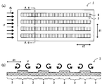
- FIG. 1A and 1B are schematic plan and cross-sectional views illustrating a gas drag reduction structure of the present disclosure
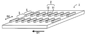
- FIG. 1 is a schematic perspective view illustrating a gas drag reduction structure of the present disclosure
- FIG. 4 is a schematic diagram illustrating gas flow in the gas resistance reduction structure of the present disclosure
- FIG. 4 is a schematic diagram illustrating the flow of gas in the gas resistance reduction structure
- 1 is a schematic cross-sectional view illustrating a gas drag reduction structure of the present disclosure
- FIG. 1 is a schematic perspective view illustrating a gas drag reduction structure of the present disclosure
- FIG. 1A and 1B are schematic plan and cross-sectional views illustrating a gas drag reduction structure of the present disclosure
- FIG. 1A and 1B are schematic plan and cross-sectional views illustrating a gas drag reduction structure of the present disclosure
- FIG. 1 is a schematic plan view illustrating a gas drag reduction structure of the present disclosure
- FIG. FIG. 4 is a schematic cross-sectional view illustrating an uneven portion of the gas resistance reduction structure of the present disclosure
- FIG. 4 is a schematic cross-sectional view illustrating protrusions in the protrusions and recesses of the gas resistance reduction structure of the present disclosure
- 1 is a schematic plan view illustrating a gas drag reduction structure of the present disclosure
- FIG. 1 is a schematic side view illustrating an application example of a gas drag reduction structure of the present disclosure
- FIG. 2 is a schematic diagram illustrating a method for manufacturing a film-like gas resistance reducing structure of the present disclosure
- FIG. 10 is a schematic diagram illustrating another method of manufacturing a film-like gas resistance reducing structure
- 1 is a schematic perspective view illustrating a film-like gas drag reducing structure of the present disclosure
- FIG. 11 is a schematic perspective view illustrating another film-like gas resistance reducing structure
- 1A and 1B are a schematic plan view and a cross-sectional view illustrating a resin molded product of the present disclosure
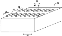
- FIG. 1 is a schematic perspective view illustrating a resin molded product of the present disclosure
- FIG. 1 is a schematic cross-sectional view illustrating a shaping mold of the present disclosure
- FIG. 4A is a schematic plan view and a cross-sectional view illustrating the concave-convex structure of the shaping mold of the present disclosure
- FIG. 4 is a schematic perspective view illustrating the concave-convex structure in the shaping mold of the present disclosure
- FIG. 4 is a schematic perspective view illustrating the concave-convex structure in the shaping mold of the present disclosure
- FIG. 4 is a schematic cross-sectional view illustrating recesses in the concave-convex portion of the shaping mold of the present disclosure
- 1A and 1B are schematic side and front views illustrating a moving body of the present disclosure
- FIG. FIG. 4A is a schematic plan view and a cross-sectional view illustrating a gas resistance reduction structure in the mobile body of the present disclosure
- FIG. 4 is a schematic perspective view illustrating a gas resistance reduction structure in the mobile body of the present disclosure
- FIG. 4 is a schematic diagram illustrating gas flow in the gas resistance reduction structure in the mobile body of the present disclosure
- FIG. 4 is a schematic cross-sectional view illustrating an uneven resin film having a gas resistance reducing structure in the mobile object of the present disclosure
- FIG. 4 is a schematic cross-sectional view illustrating an uneven resin film having a gas resistance reducing structure in the mobile object of the present disclosure
- 1 is a schematic perspective view illustrating a moving body of the present disclosure
- FIG. FIG. 4A is a schematic top view, a side view and a rear view showing a track-shaped model
- film includes sheets and plates.
- a first portion having a plurality of convex portions and concave portions and a second portion are arranged on the first surface, and the above-described
- the height from the bottom of the recess to the top of the protrusion is 10 ⁇ m or more and 1000 ⁇ m or less
- the length of the first portion in the second direction is 30 mm or more
- the length of the first portion in the first direction intersecting the second direction is The width of the first part and the width of the second part are 0.2 mm or more and 50 mm or less.
- the present disclosure utilizes a technique of generating vortices at the interface between rough and smooth surfaces to suppress flow separation.
- the frictional resistance of the rough surface becomes greater than the frictional resistance of the smooth surface. Therefore, the flow velocity of the gas is high on the smooth surface, and the flow velocity of the gas is low on the rough surface, resulting in a difference in the flow velocity of the gas between the smooth surface and the rough surface.
- vortices are generated at the interface between rough and smooth surfaces.
- the first portion has a plurality of protrusions and recesses, and is a portion with high gas frictional resistance.
- the second part is a part where gas frictional resistance is small. Therefore, when the gas flows along the first surface of the gas resistance reduction structure, a vortex is generated at the boundary between the first portion and the second portion.
- the second part is a part where gas frictional resistance is smaller than that of the first part.
- the second part has, for example, a flat surface without protrusions and recesses.
- the second part may have, for example, a protrusion or a recess, in which case the height of the protrusion or the depth of the recess in the second part is the height or depth of the protrusion in the first part. smaller than the depth of the recess.
- the "first part” may be referred to as the "uneven part”
- the “second part” may be referred to as the "flat part”.
- FIGS. 1(a) to (c) and FIG. 2 are a schematic plan view, a cross-sectional view, and a perspective view showing an example of the gas resistance reduction structure of the present disclosure
- FIG. FIG. 1(c) is a sectional view taken along line AA
- FIG. 1(c) is a sectional view taken along line BB of FIG. 1(a)
- FIG. 2 is a perspective view of FIG. 1(a).
- an uneven portion 2 having a plurality of convex portions 11 and concave portions 12 and a flat portion 3 extend in a first direction d1. are arranged alternately.
- the height H1 of the uneven portion 2 is within a predetermined range
- the length L1 of the uneven portion 2 in the second direction d2 perpendicular to the first direction d1 is equal to or greater than a predetermined value
- the uneven portion 2 in the first direction d1 and the width W2 of the flat portion 3 are within a predetermined range.
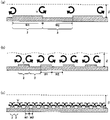
- FIGS. 3(a) and 3(b) are schematic diagrams illustrating gas flow in the gas resistance reduction structure of the present disclosure
- FIG. 3(b) is a cross-sectional view taken along the line AA of FIG. 3(a). is.
- the length L1 of the uneven portion 2 in the second direction d2 is equal to or greater than a predetermined value, so that the vortex near the boundary between the uneven portion 2 and the flat portion 3 V can be efficiently generated.
- Drag forces acting on the object include, for example, frictional resistance and pressure resistance.
- Frictional resistance is generated by the friction between the gas and the surface.
- pressure resistance is generated by the pressure difference between the front and rear. In other words, pressure resistance is generated by flow separation.
- pressure resistance is a problem in, for example, moving bodies such as automobiles, trains, and aircraft; pipes such as ducts and gas pipes; wind turbines;
- the flow velocity of the gas flowing through these objects is, for example, approximately 3 m/s to 250 m/s (approximately 10 km/h to 900 km/h).
- the height H1 of the uneven portion 2 is appropriately adjusted within a predetermined range.
- a vortex V can be easily generated in the vicinity of the boundary with the flat portion 3 . Therefore, separation of the flow from the surface of the gas resistance reduction structure can be suppressed, and pressure resistance can be reduced.
- the uneven portion may increase the frictional resistance. In this case, even if the pressure resistance is reduced, the frictional resistance is increased, and as a result, the gas resistance may not be reduced.
- the height H1 of the uneven portion 2 is within a predetermined range, so that pressure resistance can be reduced while suppressing an increase in frictional resistance due to the uneven portion.
- the profit margin of pressure resistance reduction can be made larger than the increase in frictional resistance due to the uneven portion.
- a very thin layer on the surface of the object is strongly affected by viscosity.
- a layer strongly affected by this viscosity is called a boundary layer.
- FIG. 4A to 4C are schematic diagrams showing the relationship between the widths of the uneven portion and the flat portion in the first direction and the vortices generated near the boundary between the uneven portion and the flat portion in the gas resistance reduction structure. is.
- FIG. 4A when the width W1 of the uneven portion 2 and the width W2 of the flat portion 3 in the first direction are too large, a large vortex V is generated near the boundary between the uneven portion 2 and the flat portion 3. Although generated, the vortex V does not wrap around the central portion of the uneven portion 2 and the central portion of the flat portion 3 .
- FIG. 4A when the width W1 of the uneven portion 2 and the width W2 of the flat portion 3 in the first direction are too large, a large vortex V is generated near the boundary between the uneven portion 2 and the flat portion 3. Although generated, the vortex V does not wrap around the central portion of the uneven portion 2 and the central portion of the flat portion 3 .
- the width W1 of the uneven portion 2 and the width W2 of the flat portion 3 in the first direction d1 are within a predetermined range, so that, for example, in FIG. As shown, a large vortex V is generated near the boundary between the uneven portion 2 and the flat portion 3, and the vortex V can be generated in the entire boundary layer.
- an uneven portion having a plurality of convex portions and concave portions and a flat portion are arranged, and the length of the uneven portion in the second direction is equal to or greater than a predetermined value,
- the height of the uneven portion is within a predetermined range, and the width of the uneven portion and the width of the flat portion in a first direction that intersects the second direction are within a predetermined range.
- a vortex can be generated efficiently in Furthermore, a vortex can be generated in the vicinity of the boundary between the uneven portion and the flat portion, and the vortex can be increased in the direction in which the boundary line between the uneven portion and the flat portion extends. Therefore, separation of the flow from the surface of the gas resistance reduction structure can be effectively suppressed.
- gas resistance reduction structure of the present disclosure by applying the gas resistance reduction structure of the present disclosure to the surface of an object, pressure resistance among gas resistances can be reduced.
- pressure resistance among gas resistances can be reduced.
- the length of the concavo-convex portion in the second direction is 30 mm or more, preferably 50 mm or more. If the length of the concave-convex portion in the second direction is too short, no vortex is generated near the boundary between the concave-convex portion and the flat portion, and there is a possibility that the effect of suppressing flow separation cannot be obtained. Further, since the length of the uneven portion in the second direction is within the above range, it is possible to efficiently generate a vortex in the vicinity of the boundary between the uneven portion and the flat portion. Also, the length of the uneven portion in the second direction is, for example, preferably 1000 mm or less, and more preferably 200 mm or less.
- the length of the uneven portion in the second direction is preferably 30 mm or more and 1000 mm or less, more preferably 50 mm or more and 1000 mm or less, and even more preferably 50 mm or more and 200 mm or less.
- the length L1 of the uneven portion 2 in the second direction d2 is the distance from one end to the other end of the uneven portion 2 in the second direction d2, as shown in FIG.
- the length of the uneven portion in the second direction is the length of the uneven portion in the second direction. It means the distance from the end of the projection located at one end to the end of the projection located at the other end.
- the length of the uneven portion in the second direction is located at one end of the uneven portion in the second direction.
- the length of the uneven portion in the second direction is, for example, as shown in FIG. 1(a) , the length L1 of the uneven portion 2 on the plane in the second direction d2.
- the length of the uneven portion in the second direction is the length of the uneven portion on the curved surface in the second direction d2. 2 length L1.
- the height of the uneven portion is 10 ⁇ m or more, preferably 20 ⁇ m or more, and more preferably 50 ⁇ m or more.
- the height of the uneven portion is 1000 ⁇ m or less, preferably 800 ⁇ m or less, more preferably 500 ⁇ m or less, and particularly preferably 200 ⁇ m or less.
- the height of the uneven portion is 10 ⁇ m or more and 1000 ⁇ m or less, preferably 15 ⁇ m or more and 800 ⁇ m or less, more preferably 20 ⁇ m or more and 500 ⁇ m or less, further preferably 20 ⁇ m or more and 200 ⁇ m or less, and 50 ⁇ m or more. 200 ⁇ m or less is particularly preferred.
- moving objects such as automobiles, trains, and aircraft; pipes such as ducts and gas pipes; windmills; about 10 km/h or more and 900 km/h or less.
- the flow velocity is within the above range, by appropriately adjusting the height of the uneven portion within the above range, vortices can be easily generated in the vicinity of the boundary between the uneven portion and the flat portion.
- the speed of a car is about 10 km/h or more and 120 km/h or less, and in this case, the flow speed of the air flowing through the car is about 3 m/s or more and 33 m/s or less, that is, about 10 km/h or more and 120 km/h or less. be.
- the height of the uneven portion is about 1/100 or more and 1/10 or less of the thickness of the boundary layer. Further, the faster the gas flow, the thinner the thickness of the boundary layer. Therefore, the higher the gas flow, the lower the height of the irregularities within the above range.
- the height H1 of the uneven portion 2 refers to the height from the bottom of the concave portion 12 to the top of the convex portion 11 of the uneven portion 2, for example, as shown in FIG. 1(c).
- the height of the uneven portion when the convex portion protrudes from the surface of the flat portion, the height of the uneven portion is the height of the convex portion from the bottom portion of the concave portion located between two adjacent convex portions. Refers to the height to the top.
- the height of the uneven part when the recess is recessed with respect to the surface of the flat part, the height of the uneven part is the height from the bottom of the recess to the top of the protrusion located between two adjacent recesses.
- the width of the uneven portion in the first direction is 0.2 mm or more, preferably 1 mm or more.
- the width of the uneven portion in the first direction is 50 mm or less, preferably 25 mm or less.
- the width of the uneven portion in the first direction is 0.2 mm or more and 50 mm or less, preferably 1 mm or more and 25 mm or less. Since the width of the uneven portion in the first direction is within the above range, a large vortex V is generated near the boundary between the uneven portion 2 and the flat portion 3 as shown in FIG. A vortex V can be generated as a whole.
- the width of the uneven portion in the first direction is the same as the thickness of the boundary layer. Further, the faster the gas flow rate, the thinner the thickness of the boundary layer. Therefore, it is preferable that the faster the gas flow rate, the smaller the width of the uneven portion in the first direction within the above range.
- the width of the uneven portion in the first direction may be the same as or different from the width of the flat portion in the first direction, which will be described later, as long as it is within the above range. Above all, it is preferable that the width of the uneven portion in the first direction and the width of the flat portion in the first direction are the same. In this case, vortices can be generated more efficiently in the vicinity of the boundary between the uneven portion and the flat portion.
- the width W1 of the uneven portion 2 in the first direction d1 is, for example, from one end of the uneven portion 2 in the first direction d1 to the other end as shown in FIGS. is the distance between
- the width of the uneven portion in the first direction is the width of the uneven portion 2 on the plane in the first direction d1.
- the width W1 of is the width of the uneven portion 2 on the curved surface in the first direction d1.
- first direction intersects with the second direction.
- first direction is preferably orthogonal to the second direction.
- the angle between the first direction and the second direction is, for example, preferably 85° or more and 95° or less, more preferably 90°.
- the convex portion may protrude with respect to the surface of the flat portion, and the concave portion may be concave with respect to the surface of the flat portion.
- FIGS. 2 and 7B are examples in which the convex portion 11 of the uneven portion 2 protrudes from the surface of the flat portion 3, and FIGS. This is an example in which the recessed portion 12 of the portion 2 is recessed with respect to the surface of the flat portion 3 .
- the convex portion protrudes with respect to the surface of the flat portion. In such a case, a vortex can be easily generated in the vicinity of the boundary between the uneven portion and the flat portion.
- the bottom of the concave portion 12 is normally located on the same plane as the surface of the flat portion 3, as shown in FIG.
- the top of the convex portion 11 is normally located on the same plane as the surface of the flat portion 3, as shown in FIG. 6, for example.
- the uneven part has a plurality of protrusions and recesses.
- a plurality of convex portions and concave portions are arranged so as to be uniformly distributed.
- the pattern shape of the projections and recesses in plan view may be, for example, a regular pattern or a random pattern.
- regular patterns for example, patterns such as lines, dots, and lattices can be used.
- Line-shaped patterns include, for example, straight lines; wavy lines such as sine waves and triangular waves; and the like. Among them, the linear pattern is preferably a linear pattern.
- examples of the dot arrangement include square lattice arrangement, rectangular lattice arrangement, triangular lattice arrangement, hexagonal lattice arrangement, rhombic lattice arrangement, and parallelogram lattice arrangement.
- the dot arrangement is preferably a triangular lattice arrangement or a rhombic lattice arrangement. In the case of such an arrangement of dots, eddies can be easily generated in the vicinity of the boundary between the uneven portion and the flat portion.
- examples of the lattice pattern include square lattice, rectangular lattice, triangular lattice, hexagonal lattice, rhombic lattice, and parallelogram lattice.
- FIGS. 2 and 6 are examples in which the pattern shapes of the projections 11 and the recesses 12 are linear in plan view.
- FIGS. 7A to 7C show an example in which the pattern shape of the projections 11 in a plan view is a dot shape and has a triangular lattice arrangement.
- 8(a) and 8(b) are examples in which the pattern shape of the recesses 12 in a plan view is a dot shape and has a triangular lattice arrangement.
- 7B and 7C are cross-sectional views taken along line AA in FIG. 7A
- FIG. 8B is a cross-sectional view along line AA in FIG. 8A.
- FIG. 9 shows an example in which the pattern shape of the projections 11 in a plan view is a lattice shape, which is a rectangular lattice shape.
- the longitudinal direction of the linear pattern of the projections and recesses preferably intersects the second direction. More preferably substantially perpendicular to the first direction, that is, substantially parallel to the first direction.
- the longitudinal direction of the linear pattern of the convex portion and the concave portion preferably intersects the second direction. and substantially perpendicular to the second direction as shown in FIG. 6, ie substantially parallel to the first direction. That is, it is preferable that the concave-convex portion has a plurality of convex portions and concave portions linearly extending along the first direction.
- the gas resistance reduction structure of the present disclosure is arranged such that the first direction d1 is substantially perpendicular to the flow direction dF of the gas F , that is, the gas F It is preferably arranged and used such that the second direction d2 is substantially parallel to the flow direction dF . Therefore, when the longitudinal direction of the line-shaped pattern of protrusions and recesses intersects the second direction, the longitudinal direction of the line-shaped pattern of protrusions and recesses is aligned with the flow direction of the gas.
- the uneven portion 2 has a plurality of convex portions 11 and concave portions 12 linearly extending along the first direction d1, and the convex portion 11 is Protruding is particularly preferred. In such a case, a vortex can be efficiently generated near the boundary between the uneven portion and the flat portion.
- the angle formed by the longitudinal direction of the line-shaped pattern of the protrusions and recesses is, for example, 90° ⁇ It is preferably 45°, that is, 45° or more and 135° or less.
- the angle formed by the longitudinal direction of the linear pattern and the second direction is, for example, 90°. It is preferably ⁇ 45°, that is, 45° or more and 135° or less.
- the angle formed by the longitudinal direction of the line-shaped pattern and the gas flow direction is, for example, 90°. ° ⁇ 45°, that is, 45° or more and 135° or less.
- the angle formed by the longitudinal direction of the linear pattern and the gas flow direction is, for example, It is preferably 90 ⁇ 45°, that is, 45° or more and 135° or less.
- the longitudinal direction of the line-shaped pattern of the protrusions and recesses when the longitudinal direction of the line-shaped pattern of the protrusions and recesses is substantially parallel to the first direction, it means that the angle between the longitudinal direction of the line-shaped pattern and the first direction is 0° ⁇ 5°, that is, -5° or more and 5° or less.
- the longitudinal direction of the linear pattern of the protrusions and recesses when the longitudinal direction of the linear pattern of the protrusions and recesses is substantially parallel to the first direction, it means that the angle formed by the longitudinal direction of the linear pattern and the first direction is 0° ⁇ 5°, that is, -5° or more and 5° or less.
- the angle formed by the longitudinal direction of the line-shaped pattern of the protrusions and recesses is 90°. ⁇ 5°, that is, 85° or more and 95° or less.
- the longitudinal direction of the linear pattern of the protrusions and recesses is substantially perpendicular to the direction of gas flow, it means that the angle formed by the longitudinal direction of the linear pattern and the direction of gas flow is 90°. ° ⁇ 5°, that is, 85° or more and 95° or less.
- the longitudinal direction of a line-shaped pattern is, for example, the direction in which the linear pattern extends in the case of a linear pattern, and the direction in which the wavy pattern extends in the case of a wavy pattern.
- the angle between the longitudinal direction of the linear pattern and the second direction is, for example, preferably 45° or more and 135° or less, more preferably 80° or more and 100° or less, and 85° or more and 95° or more. ° or less is more preferable.
- the angle formed by the longitudinal direction of the linear pattern and the second direction is, for example, preferably 45° or more and 135° or less, and is 80° or more and 100° or less. is more preferably 85° or more and 95° or less.
- the angle formed by the longitudinal direction of the line-shaped pattern and the gas flow direction is, for example, preferably 45° or more and 135° or less, more preferably 80° or more and 100° or less, and 85° or more. It is more preferably 95° or less.
- the angle formed by the longitudinal direction of the linear pattern and the gas flow direction is preferably 45° or more and 135° or less, and is preferably 80° or more and 100° or less. 85° or more and 95° or less is more preferable.
- the width of the line-shaped projections is preferably, for example, 1 to 2 times the height of the projections and recesses.
- the width of the linear projections is preferably 1 to 2 times the height of the projections and recesses. If the width of the line-shaped protrusions is too small, it may be difficult to form the protrusions and recesses. Moreover, if the width of the line-shaped convex portion is too large, it may become difficult to sufficiently generate a vortex in the vicinity of the boundary between the uneven portion and the flat portion.
- the width of the linear convex portion is the width W3 of the convex portion 11, for example, as shown in FIGS.
- the width of the line-shaped recesses is, for example, preferably 1 time or more, or 4 times or more, the height of the projections and recesses. is more preferable.
- the width of the linear concave portion is, for example, preferably 12 times or less, more preferably 10 times or less, the height of the uneven portion.
- the width of the linear concave portion is, for example, preferably 1 to 12 times, more preferably 4 to 10 times, the height of the uneven portion.
- the width of the linear recesses is, for example, preferably 1 or more times the height of the projections and recesses. Four times or more is more preferable.
- the width of the linear concave portion is, for example, preferably 12 times or less, more preferably 10 times or less, the height of the uneven portion. Further, the width of the linear concave portion is preferably 1 to 12 times, more preferably 4 to 10 times, the height of the uneven portion.
- the width of the line-shaped concave portions is too small, the density of the convex portions becomes high, and it may become difficult to sufficiently generate vortices in the vicinity of the boundary between the concave-convex portion and the flat portion. Also, if the width of the linear concave portions is too large, the density of the convex portions becomes low, and it may become difficult to sufficiently generate vortices in the vicinity of the boundary between the concave and convex portions and the flat portion. In addition, when the width of the line-shaped concave portion is 4 times or more and 10 times or less than the height of the uneven portion, a vortex is generated in the vicinity of the boundary between the uneven portion and the flat portion, and separation of the flow can be effectively suppressed. .
- the width of the line-shaped recess is, for example, the width W4 of the recess 12 as shown in FIGS.
- the width of the recess 12 is zero.
- the pitch of the line-shaped projections is, for example, preferably twice or more, preferably five times the height of the projections and depressions. It is more preferable to be above.
- the pitch of the linear projections is, for example, preferably 14 times or less, and more preferably 12 times or less, the height of the projections and depressions.
- the pitch of the line-shaped protrusions is preferably, for example, 2 to 14 times, more preferably 5 to 12 times the height of the protrusions and recesses.
- the pitch of the linear projections is preferably at least twice the height of the projections and recesses, for example. , more preferably 5 times or more.
- the pitch of the linear protrusions is, for example, preferably 14 times or less, more preferably 12 times or less, the height of the unevenness.
- the pitch of the linear protrusions is preferably 2 to 14 times, more preferably 5 to 12 times, the height of the protrusions and recesses. If the pitch of the line-shaped protrusions is too small, the density of the protrusions increases, and it may become difficult to sufficiently generate vortices in the vicinity of the boundary between the uneven portion and the flat portion. Also, if the pitch of the linear projections is too large, the density of the projections will be low, and it may be difficult to sufficiently generate vortices in the vicinity of the boundary between the uneven portion and the flat portion.
- the pitch of the linear protrusions is, for example, the pitch P1 of the protrusions 11 as shown in FIGS.
- the size of the dot-shaped projections in plan view is, for example, 1 to 2 times the height of the uneven portion. is preferred. If the size of the dot-shaped protrusions is too small, it may become difficult to form the protrusions and recesses. Moreover, if the size of the dot-shaped convex portion is too large, it may become difficult to sufficiently generate a vortex in the vicinity of the boundary between the uneven portion and the flat portion.
- the size of the dot-shaped recesses in plan view is, for example, preferably 1 time or more, or 4 times the height of the uneven part. It is more preferable to be above.
- the size of the dot-shaped concave portions in plan view is preferably, for example, 12 times or less, more preferably 10 times or less, the height of the uneven portions.
- the size of the dot-shaped recesses in a plan view is, for example, preferably 1 to 12 times, more preferably 4 to 10 times, the height of the recesses and protrusions.
- the size of the dot-shaped concave portions is too small, the density of the convex portions becomes high, and it may become difficult to sufficiently generate vortices in the vicinity of the boundary between the uneven portion and the flat portion. Also, if the size of the dot-shaped concave portions is too large, the density of the convex portions will be low, and it may be difficult to sufficiently generate vortices in the vicinity of the boundary between the concave-convex portion and the flat portion. In addition, when the size of the dot-shaped recesses is 4 times or more and 10 times or less than the height of the uneven part, a vortex is generated near the boundary between the uneven part and the flat part, effectively suppressing the separation of the flow. can.
- the size of the dot-shaped protrusions or recesses in plan view refers to, for example, the diameter when the plan view shape of the protrusions or recesses is circular, and the plan view shape of the protrusions or recesses is elliptical. In the case of a shape, it refers to the major axis, and in the case that the projection or recess has a rectangular shape in plan view, it refers to the length of the diagonal line.
- the pitch of the dot-shaped projections or recesses is, for example, preferably twice or more the height of the projections and recesses. It is more preferably 5 times or more.
- the pitch of the dot-shaped protrusions or recesses is preferably, for example, 14 times or less, more preferably 12 times or less, the height of the protrusions and recesses.
- the pitch of the dot-shaped protrusions or recesses is, for example, preferably 2 to 14 times, more preferably 5 to 12 times the height of the protrusions and recesses.
- the pitch of the dot-shaped protrusions or recesses is too small, the density of the protrusions increases, which may make it difficult to sufficiently generate vortices in the vicinity of the boundaries between the protrusions and recesses and the flat portions. Also, if the pitch of the dot-shaped protrusions or recesses is too large, the density of the protrusions will be low, and it may be difficult to generate sufficient vortices in the vicinity of the boundary between the protrusions and recesses and the flat portion.
- the pitch of dot-shaped protrusions or recesses refers to the distance between adjacent protrusions or recesses.
- the width of the lattice-shaped projections is preferably, for example, 1 to 2 times the height of the irregularities. If the width of the grid-shaped protrusions is too small, it may be difficult to form the uneven portions. Moreover, if the width of the grid-shaped convex portion is too large, it may become difficult to sufficiently generate vortices in the vicinity of the boundary between the uneven portion and the flat portion.
- the interval between the lattice-shaped projections is, for example, preferably 1 time or more, or 4 times or more, the height of the projections and depressions. It is more preferable to have On the other hand, the interval between the lattice-shaped projections is preferably, for example, 12 times or less, more preferably 10 times or less, as large as the height of the projections and depressions. Also, the interval between the lattice-shaped projections is preferably, for example, 1 to 12 times, more preferably 4 to 10 times, the height of the projections and recesses.
- the intervals between the grid-like projections are too small, the density of the projections increases, and it may become difficult to sufficiently generate vortices in the vicinity of the boundary between the uneven portion and the flat portion.
- the intervals between the lattice-shaped convex portions are too large, the density of the convex portions will be low, and it may become difficult to generate sufficient vortices in the vicinity of the boundary between the uneven portion and the flat portion.
- the interval between the lattice-shaped projections is 4 to 10 times the height of the uneven portion, a vortex is generated near the boundary between the uneven portion and the flat portion, effectively suppressing flow separation. can.
- the width of the concave portion in the lattice shape is, for example, preferably 1 time or more, and 4 times or more the height of the uneven portion. is more preferred.
- the width of the grid-like concave portion is, for example, preferably 12 times or less, more preferably 10 times or less, the height of the uneven portion.
- the width of the grid-like concave portion is, for example, preferably 1 to 12 times, more preferably 4 to 10 times, the height of the uneven portion.
- the width of the grid-shaped concave portions is too small, the density of the convex portions increases, and it may become difficult to sufficiently generate vortices in the vicinity of the boundary between the uneven portion and the flat portion. Moreover, if the width of the grid-shaped concave portion is too large, the density of the convex portions will be low, and it may be difficult to sufficiently generate vortices in the vicinity of the boundary between the uneven portion and the flat portion. Further, when the width of the grid-like concave portion is 4 times or more and 10 times or less than the height of the uneven portion, a vortex is generated in the vicinity of the boundary between the uneven portion and the flat portion, and separation of the flow can be effectively suppressed. .
- the interval between the concave portions in the lattice shape is preferably, for example, 1 to 2 times the height of the concave and convex portions. If the intervals between the grid-like concave portions are too small, it may become difficult to form the uneven portions. Moreover, if the intervals between the grid-like concave portions are too large, it may become difficult to sufficiently generate vortices in the vicinity of the boundary between the uneven portion and the flat portion.
- the pitch of the lattice-shaped projections or recesses is, for example, preferably twice or more the height of the projections and recesses. It is more preferably 5 times or more.
- the pitch of the lattice-like protrusions or recesses is, for example, preferably 14 times or less, more preferably 12 times or less, the height of the protrusions and recesses.
- the pitch of the lattice-shaped protrusions or recesses is, for example, preferably 2 to 14 times, more preferably 5 to 12 times the height of the protrusions and recesses.
- the pitch of the grid-like protrusions or recesses is too small, the density of the protrusions increases, and it may become difficult to sufficiently generate vortices in the vicinity of the boundary between the protrusions and recesses and the flat portion. Also, if the pitch of the grid-shaped protrusions or recesses is too large, the density of the protrusions will be low, and it may be difficult to generate sufficient vortices in the vicinity of the boundary between the uneven part and the flat part.
- the dimensions of the concave and convex portions, concave portions and convex portions can be measured by observing the surface of the gas resistance reducing structure or a cross section in the thickness direction using a laser displacement sensor.
- the cross-sectional shape of the protrusions and recesses is not particularly limited, and examples thereof include rectangular, trapezoidal, triangular, semicircular, and semielliptical shapes.
- FIG. 10(a) is an example in which the cross-sectional shape of the convex portion 11 and the concave portion 12 is rectangular
- FIG. 10(b) is an example in which the cross-sectional shape of the convex portion 11 and the concave portion 12 is trapezoidal.
- 10(c) to (e) are examples in which the cross-sectional shape of the convex portion 11 is triangular
- FIG. 10(f) is an example in which the cross-sectional shape of the convex portion 11 is semi-elliptical.
- g) to (h) are examples in which the cross-sectional shape of the recess 12 is triangular
- FIG. 10(i) is an example in which the cross-sectional shape of the recess 12 is semicircular.
- the cross-sectional shape of the protrusions or recesses is preferably trapezoidal, semicircular, or semielliptical. In the case of these shapes, it is easy to form the uneven portion, and the durability of the uneven portion can be enhanced.
- the convex portion has a roundness, that is, a curved surface at a portion extending from the top portion to the side portion of the convex portion and connected to the top portion.
- FIGS. 11(a) and 11(b) are schematic cross-sectional views illustrating convex portions in the gas resistance reducing structure of the present disclosure.
- 11(a) is a schematic cross-sectional view of the protrusion in the first direction
- FIG. 11(b) is a schematic cross-sectional view of the protrusion in the second direction.
- the convex portion 11 has a portion 11R extending from the top portion 11T to the side portion 11S of the convex portion 11, and is rounded. is doing. That is, the convex portion 11 has a curved surface at the portion 11R. In this way, when the convex portion 11 has the rounded portion 11R, the scratch resistance and wear resistance of the convex portion 11 can be improved. Further, the frictional resistance at the portion 11R on the boundary side of the convex portion 11 can be suppressed with respect to the vortex generated at the boundary between the first portion and the second portion. Therefore, it is expected that the effect of the vortex, that is, the effect of suppressing separation of the gas from the surface will be further enhanced.
- the radius of curvature of the curved surface at the portion of the convex portion is, for example, preferably 10 ⁇ m or more, more preferably 20 ⁇ m or more.
- the radius of curvature of the curved surface is preferably, for example, 400 ⁇ m or less, more preferably 200 ⁇ m or less.
- the radius of curvature of the curved surface is preferably 10 ⁇ m or more and 400 ⁇ m or less, more preferably 20 ⁇ m or more and 200 ⁇ m or less. If the radius of curvature of the curved surface is too small, it may be difficult to improve the scratch resistance and wear resistance of the gas drag reduction structure. Moreover, when the radius of curvature of the curved surface is excessively large, the height of the uneven portion must be increased. If the height of the uneven portion exceeds a size suitable for reducing gas resistance, the effect of reducing gas resistance may become insufficient.
- the curvature radius of the curved surface at the above-mentioned portion of the convex portion refers to the radius of curvature of the curve at the above-mentioned portion of the convex portion in the cross section in the thickness direction of the gas resistance reducing structure.
- FIG. 11A is a cross-sectional view in the thickness direction of the gas resistance reducing structure, and is a cross-sectional view of the convex portion in the first direction.
- FIG. 11B is a cross-sectional view of the gas resistance reducing structure in the thickness direction, and is a cross-sectional view of the convex portion in the second direction.
- the radius of curvature of the curved surface of the portion 11R of the projection 11 is the radius of curvature r1 of the curve of the portion 11R of the projection 11.
- the number of convex portions and the number of concave portions are respectively plural, and are appropriately set so as to satisfy the dimensions of the concave and convex portions, the concave portions, and the convex portions.
- the number of protrusions and the number of recesses in the uneven portion are respectively 14 or more, may be 83 or more, or may be 181 or more.
- the number of protrusions and the number of recesses are, for example, 1500 or less, may be 714 or less, or may be 200 or less.
- the number of convex portions and the number of concave portions may be, for example, 14 or more and 1500 or less, may be 83 or more and 714 or less, or may be 181 or more and 200 or less.
- the shape of the uneven portion in plan view is not particularly limited as long as it can generate a vortex near the boundary between the uneven portion and the flat portion, and examples thereof include a rectangular shape and an arc shape.
- FIG. 1A shows an example in which the uneven portion 2 has a rectangular shape in plan view
- FIG. 12 shows an example in which the uneven portion 2 has a rectangular shape and an arc shape in plan view.
- the shape of the concave-convex portion in a plan view is a rectangular shape.
- the uneven portion and the flat portion are arranged.
- the uneven portions and the flat portions may be alternately arranged parallel to the first direction, or alternately non-parallel to the first direction.
- FIG. 1A shows an example in which uneven portions 2 and flat portions 3 are alternately arranged in parallel in the first direction d1, and FIG. is arranged non-parallel to .
- uneven portions and flat portions may be alternately arranged non-parallel in the first direction.
- it is preferable that the uneven portions and the flat portions are alternately arranged in parallel in the first direction.
- the width of the flat part in the first direction is 0.2 mm or more, preferably 1 mm or more.
- the width of the flat portion in the first direction is 50 mm or less, preferably 25 mm or less.
- the width of the flat portion in the first direction is 0.2 mm or more and 50 mm or less, preferably 1 mm or more and 25 mm or less. Since the width of the flat portion in the first direction is within the above range, a large vortex V is generated near the boundary between the uneven portion 2 and the flat portion 3 as shown in FIG. A vortex V can be generated as a whole.
- the width of the flat portion in the first direction is more preferably the same as the boundary layer thickness. Further, the faster the gas flow rate, the thinner the thickness of the boundary layer. Therefore, it is preferable that the faster the gas flow rate, the smaller the width of the flat portion in the first direction within the above range.
- the width W2 of the flat portion 3 in the first direction d1 is the width W2 in the first direction d1 in the flat portion 3 positioned between adjacent uneven portions 2 as shown in FIGS. The distance from one end of the flat portion 3 to the other end.
- the width W2 of the flat portion in the first direction is the flat portion 3 on the plane in the first direction d1.
- the width W2 of is the width of the flat portion in the first direction.
- an ionizing radiation curable resin composition such as an ultraviolet curable resin composition or an electron beam curable resin composition or a thermosetting resin
- a curable resin composition such as a composition
- a method of applying the curable resin composition in a predetermined pattern on a substrate and curing A so-called photopolymer method (2P method) in which an object is applied, a mold is pressed against the coating film, the ultraviolet curable resin composition is cured by irradiating it with ultraviolet rays, and then it is peeled off from the mold; thermoplastic resin film , a method of embossing the surface of a substrate such as a rubber sheet or a metal plate;
- the method for applying the curable resin composition is not particularly limited as long as it can be applied in a desired pattern.
- a screen printing method and the like can be mentioned.
- gas resistance reduction structure of the present disclosure when applied to the surface of an object, for example, a film-like gas resistance reduction structure may be arranged on the surface of the object, or the gas resistance reduction structure may be directly applied to the surface of the object.
- a reduction structure may be formed.
- the gas resistance reduction structure of the present disclosure is designed such that the angle between the boundary line between the uneven portion and the flat portion and the gas flow direction is, for example, 0° ⁇ 15°, that is, ⁇ 15° or more and 15° or less. It is preferable to be arranged and used so as to be That is, in the gas resistance reduction structure of the present disclosure, the angle between the second direction and the gas flow direction is, for example, 0° ⁇ 15°, that is, ⁇ 15° or more and 15° or less. It is preferable that they are arranged and used. In other words, the gas resistance reduction structure of the present disclosure is configured such that the angle between the first direction and the gas flow direction is, for example, 90° ⁇ 15°, that is, 75° or more and 105° or less. It is preferably used by being placed in the
- the gas resistance reducing structure of the present disclosure is such that the boundary line between the uneven portion 2 and the flat portion 3 is substantially parallel to the flow direction dF of the gas F , as shown in FIG. It is more preferable to be placed in and used. That is, the gas resistance reduction structure of the present disclosure is configured such that the second direction d2 is substantially parallel to the flow direction dF of the gas F , as shown in FIG. More preferably, it is arranged and used so that the direction d1 is substantially vertical. As a result, a vortex can be easily generated near the boundary between the uneven portion and the flat portion, and flow separation can be suppressed.
- the boundary line between the uneven portion and the flat portion is substantially parallel to the flow direction of the gas
- the angle between the boundary line between the uneven portion and the flat portion and the flow direction of the gas is 0° ⁇ 5. °, that is, from -5° to 5°.
- the second direction being substantially parallel to the gas flow direction means that the angle formed by the second direction and the gas flow direction is 0° ⁇ 5°, that is, ⁇ 5° to 5°.
- the first direction being substantially perpendicular to the gas flow direction means that the angle formed by the first direction and the gas flow direction is 90° ⁇ 5°, that is, 85° or more and 95° or less. It means that
- the angle between the second direction and the gas flow direction is, for example, ⁇ 15° or more and 15° or less, especially ⁇ 10° or more and 10° or less, particularly ⁇ 5° or more. It is preferable to arrange and use it so that it may be 5 degrees or less.
- the angle between the first direction and the gas flow direction is, for example, 75° or more and 105° or less, especially 80° or more and 100° or less, particularly 85° or more and 95°. It is preferable that they are arranged and used as follows.
- the gas drag reduction structure of the present disclosure can be applied to the surface of an object.
- the gas resistance reduction structure of the present disclosure can be It can be applied to the surface of the housing and parts of a moving body that moves.
- the gas resistance reduction structure of the present disclosure can be applied to, for example, the inner surface of pipes such as ducts and gas pipes; the surface of blades of windmills; the surface of outlets and louvers of air conditioning equipment such as air conditioners; can.
- the gas drag reduction structure of the present disclosure is preferably applied to the surface of a housing or parts of a moving body, and the surface of a moving body that is a non-streamline object, specifically a bluff body.
- Mobile bodies that are bluff bodies include, for example, preferably trucks, buses, and the like.
- the surface of the object may be flat or curved.
- the gas resistance reduction structure of the present disclosure can reduce gas resistance, but the gas is not particularly limited.
- the gas density is preferably, for example, 0.08 kg/m 3 or more and 10 kg/m 3 or less. Among them, the gas is preferably air.
- the elongation in the first direction on the first surface is the first It is preferably less than the extension in the second direction in the plane.
- the first surface has a smaller extension in the first direction than any other direction in which the first surface extends.
- the film-shaped gas resistance reduction structure has such physical properties, even if it follows the surface of the object and is stretched in the second direction, the uneven structure constituting the gas resistance reduction structure is prevented from being damaged. can be suppressed. Therefore, the gas resistance can be effectively reduced by applying the film-like gas resistance reducing structure to the surface of an object, especially to the surface of an object having a curved surface.
- the convex portion 11 when the convex portion 11 has a form extending linearly along the first direction d1, the film-like gas resistance reducing structure has a small elongation in the first direction d1. is preferred.
- the convex portion 11 is made of a material that does not have flexibility with respect to elongation, when the film-like gas resistance reduction structure is stretched in the first direction d1, the convex portion 11 cannot withstand the stretching. Collapse and detachment may occur.
- the recesses between the plurality of protrusions 11 are arranged. Since the projections 12 are stretched, the possibility of collapsing or peeling of the projections 11 is low compared to the case where they are stretched in the first direction d1.
- the first surface has a smaller elongation in the first direction than the first surface has an elongation in the second direction.
- the film-like gas resistance reducing structure is preferably attached such that the second direction and the gas flow direction are substantially parallel to each other.
- the film-like gas resistance reducing structure is attached such that the second direction is the direction from the front portion toward the side portion along the curved surface with the small radius of curvature at the corner.
- FIG. 13 shows an example in which the film-like gas resistance reduction structure 1 is applied to the above-mentioned corresponding portion of the track 50A.
- the film-like gas resistance reducing structure may be stretched in the second direction along the curved surface with a small radius of curvature at the corners. Therefore, it is preferable that the film-like gas resistance reducing structure has a certain degree of elongation in the second direction from the viewpoint of facilitating attachment.
- the film-like gas resistance reducing structure when the film-like gas resistance reducing structure is applied to the surface of an object having a curved surface, the elongation of the first surface in the first direction is smaller than the elongation of the first surface in the second direction. It can effectively reduce the resistance.
- the concave and convex portions may be formed using a cylindrical plate.
- a cylindrical plate can be used for the photopolymer method and embossing method described above. Using a cylindrical plate is preferred for mass production.
- the convex portion 11 when the convex portion 11 has a shape extending linearly along the first direction d1, the convex portion 11 is formed by using a cylindrical plate rotating along the first direction d1. is preferably formed.
- the rotation direction of the cylindrical plate By setting the rotation direction of the cylindrical plate to be the same as the longitudinal direction of the projections 11, that is, the same direction as the first direction, when the formed projections 11 are released from the cylindrical plate, the projections 11 can be prevented from being destroyed. That is, formation of defective convex portions 11 can be reduced.
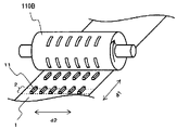
- the cylindrical plate 110A when using a cylindrical plate 110A that rotates along the second direction d2 to form convex portions 11 having a shape that extends linearly along the first direction d1, the cylindrical plate 110A The direction in which the film flows (second direction d2) and the longitudinal direction (first direction d1) of the projections 11 are different. Therefore, when the formed protrusions 11 are released from the cylindrical plate 110A, the resistance received from the cylindrical plate 110A is large. Therefore, there is a possibility that the convex portion 11 is destroyed by the cylindrical plate 110A.
- the film-like gas resistance reducing structure 1 has a shape elongated along the second direction d2.
- the cylindrical plate 110B rotating along the first direction d1 when used to form the projections 11 having a shape extending linearly along the first direction d1, the cylindrical plate 110B
- the direction in which the film flows due to the rotation of is the same as the longitudinal direction (first direction d1) of the projections 11 . Therefore, when the formed protrusions 11 are released from the cylindrical plate 110B, the resistance received from the cylindrical plate 110B is small. Therefore, it is possible to prevent the protrusion 11 from being destroyed by the cylindrical plate 110B.
- the film-like gas resistance reducing structure 1 has a shape elongated along the first direction d1.
- the film-like gas resistance reduction structure has a form that is elongated along the first direction, and by using a cylindrical plate that rotates along the first direction to form the projections, , formation defects of the convex portion can be suppressed.
- the film-like gas resistance reduction structure is elongated in the first direction, as described above. have.
- the film-shaped gas resistance reducing structure is also wound as a roll during manufacturing and transportation.
- the winding direction is preferably a direction that matches the characteristics of the film-like gas resistance reducing structure.
- the film-like gas resistance reduction structure has a small elongation in the winding direction so that the film-like gas resistance reduction structure is not adversely affected even if a tensile force acts on the film-like gas resistance reduction structure.
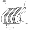
- a roll body 100A shown in FIG. 16 is a roll body in which a film-like gas resistance reduction structure 1 is wound around a winding core 101.
- the film-like gas resistance reduction structure 1 is wound along the first direction d1.
- the film-shaped gas resistance reducing structure when the elongation of the first surface in the first direction d1 is smaller than the elongation of the first surface in the direction intersecting the first direction d1, for example, the extension in the second direction d2, the roll body 100A In this case, by winding the film-like gas resistance reduction structure 1 along the first direction d1, excessive stretching of the film-like gas resistance reduction structure 1 can be suppressed.
- the film-like gas resistance reducing structure 1 has a form elongated along the first direction d1.
- a roll body 100B shown in FIG. 17 is a roll body in which the film-like gas resistance reduction structure 1 is wound along the second direction d2.
- the film-like gas resistance reducing structure when the stretch in the first direction d1 on the first surface is smaller than the stretch in the second direction d2, for example, the direction intersecting the first direction d1 on the first surface, the film-like If the gas resistance reduction structure 1 is wound along the second direction d2, the film-like gas resistance reduction structure 1 may be excessively stretched.
- the film-like gas resistance reducing structure 1 has a form elongated along the second direction d2.
- the film-shaped gas resistance reduction structure 1 is held in the state of the roll body 100B, that is, the film-shaped gas resistance reduction structure 1 is held in a state excessively stretched in the second direction d2.
- the film-like gas resistance reducing structure 1 unwound from the roll body 100B, there is a possibility that the elongation in the second direction d2 has already become small.
- the film-like gas resistance reduction structure 1 whose elongation in the second direction d2 has become small when applying it to the corners connecting the front part to the side part of the above-mentioned truck, bus, train, etc. less effective.
- the film-like gas resistance reduction structure when used as a roll body, if the elongation of the first surface in the first direction is smaller than the elongation of the first surface in the second direction, the film-like gas resistance reduction structure By winding the body along the first direction, excessive stretching of the film-like gas resistance reduction structure during winding can be suppressed.
- the film-like gas resistance reducing structure has a form that is elongated along the first direction, and the stretch of the first surface in the first direction is greater than the stretch of the first surface in the second direction. is preferably small. As a result, it is possible to suppress formation defects of the protrusions when forming the protrusions using a cylindrical plate, and it is possible to suppress excessive elongation of the film during winding.
- elongation refers to the amount of deformation when tensile force is applied to the material. Specifically, when the original length is L and the amount of elongated deformation is .DELTA.L, this .DELTA.L is called "elongation.”
- a tensile test was performed using a tensile tester or the like with the same tensile force and the same speed in each direction. It can be obtained by comparing the magnitude of deformation. It is not necessary to rupture the sample (film-like gas resistance reducing structure) to compare the magnitude of "elongation”, and it is sufficient to compare the magnitude of deformation due to elongation before rupture.
- the magnitude of the "elongation" in each direction of the film-shaped gas resistance reduction structure may be evaluated by the tensile modulus.
- the tensile modulus is JIS K7161-1:2014 (Plastics-How to determine tensile properties-Part 1: General rules) and JIS K7127:1999 (Plastics-Testing methods for tensile properties-Part 3: Measurement conditions for films and sheets ).
- the tensile modulus in each direction is measured by performing a tensile test in each direction of the sample (film-like gas resistance reducing structure) using a tensile tester. The conditions of the tensile test and the details of the tensile test are described in the Examples section below.
- the tensile modulus is the slope between two points of strain 0.05% and 0.25% on the stress/strain curve.
- the substrate, thermoplastic resin film, or resin substrate that constitutes the film-shaped gas resistance reduction structure is stretched in a specific direction. Less than the stretch in the transverse direction is preferred.
- examples of such substrates, thermoplastic resin films and resin substrates include uniaxially stretched resin substrates.
- the elongation in the direction of stretching is smaller than the elongation in the direction crossing the direction of stretching.
- the elongation in the MD (Machine Direction) direction is greater than the elongation in the TD (Transverse Direction) direction. becomes smaller.
- a resin substrate includes a biaxially oriented PET (polyethylene terephthalate) substrate. Therefore, even with a biaxially stretched resin base material, the elongation in one direction is smaller than the elongation in the other direction, e.g., the elongation in the MD direction is smaller than the elongation in the TD direction.
- a small resin base material can be used.
- a first portion having a plurality of protrusions and recesses on the first surface;
- the second part is arranged, the first part and the second part extend in a band shape in the second direction, and the elongation in the first direction intersecting the second direction on the first surface is the Less than the elongation in the second direction.
- the uneven part (first part), the flat part (second part), the manufacturing method, and the application are the uneven part, the flat part, It is the same as the manufacturing method and usage.
- the members constituting the film-shaped gas resistance reduction structure, the material and thickness of each member, and the method for manufacturing the film-shaped gas resistance reduction structure are , members constituting the concave-convex resin film in the moving body, the material and thickness of each member, and the manufacturing method of the concave-convex resin film, which will be described later.
- the resin molded product of the present disclosure is a resin molded product having an uneven structure on its surface. is arranged, the height from the bottom of the concave portion of the first portion to the top of the convex portion is 10 ⁇ m or more and 1000 ⁇ m or less, and the length of the uneven portion in the second direction is 30 mm or more, A width of the first portion and a width of the second portion in a first direction intersecting the second direction are 0.2 mm or more and 50 mm or less.
- the "first part” may be referred to as the "uneven part”
- the “second part” may be referred to as the "flat part”.
- FIGS. 18(a) to (c) and FIG. 19 are schematic plan views, cross-sectional views and perspective views showing an example of the resin molded product of the present disclosure
- FIG. FIG. 18(c) is a sectional view taken along line A
- FIG. 18(c) is a sectional view taken along line BB of FIG. 18(a)
- FIG. 19 is a perspective view of FIG. 18(a).
- the resin molded product 10 has an uneven structure 4 on its surface.
- the portions 2 and flat portions 3 are alternately arranged in the first direction d1.
- the height H1 of the uneven portion 2 is within a predetermined range
- the length L1 of the uneven portion 2 in the second direction d2 perpendicular to the first direction d1 is equal to or greater than a predetermined value
- the uneven portion 2 in the first direction d1 and the width W2 of the flat portion 3 are within a predetermined range.
- the resin molded product of the present disclosure has the same effect as the gas resistance reduction structure described above. That is, the resin molded product of the present disclosure has an uneven structure on the surface, and in the uneven structure, an uneven portion having a plurality of convex portions and concave portions and a flat portion are arranged, and unevenness in the second direction
- the length of the portion is equal to or greater than a predetermined value
- the height of the uneven portion is within a predetermined range
- the width of the uneven portion and the width of the flat portion in a first direction intersecting the second direction are within a predetermined range. Due to this, it is possible to efficiently generate a vortex in the vicinity of the boundary between the uneven portion and the flat portion.
- Concavo-convex structure In the concavo-convex structure of the resin molded product of the present disclosure, a concavo-convex portion having a plurality of convex portions and concave portions and a flat portion are arranged.
- the uneven part and the flat part are the same as the uneven part and the flat part in the gas resistance reducing structure described above, respectively.
- first direction and the second direction is the same as the relationship between the first direction and the second direction in the gas resistance reduction structure described above.
- thermoplastic resin As a material for the resin molded product, a thermoplastic resin can be used, and for example, it can be appropriately selected from general-purpose plastics and engineering plastics. Among them, acrylic resins and polycarbonates are preferable from the viewpoint of weather resistance and abrasion resistance.
- Additives such as ultraviolet absorbers, antioxidants, plasticizers, stabilizers, lubricants, fillers, coloring agents, processing aids, antistatic agents, and anti-twisting agents are added to resin molded products as necessary. may contain. Weather resistance can be enhanced when the resin molded article contains an ultraviolet absorber.
- the resin molded product may be transparent or opaque.
- the shape of the resin molded product can be any shape that can be molded, and can be of various shapes, from simple to complex.
- the thickness of the resin molded product may be any thickness that can be molded, for example, it is preferably 0.35 mm or more and 100 mm or less, more preferably 0.40 mm or more and 75 mm or less, and 0.50 mm or more and 50 mm More preferably:
- Method for producing resin molded product is not particularly limited as long as it is a molding method capable of producing a resin molded product having an uneven structure on the surface, and examples thereof include injection molding and extrusion molding. etc.
- the relationship between the boundary line between the uneven portion and the flat portion and the gas flow direction, the relationship between the second direction and the gas flow direction, and the relationship between the first direction and the gas flow direction are respectively the relationship between the boundary line between the uneven portion and the flat portion and the gas flow direction, the relationship between the second direction and the gas flow direction, and the first direction and the gas flow direction in the gas resistance reduction structure described above. It is similar to the relationship with the flow direction.
- the resin molded product of the present disclosure can be applied to the surface of an object or used as a component itself.
- the resin molded product of the present disclosure can be applied to the surface of a housing or parts of a moving body, or used as a part of a moving body.
- the moving body is the same as the moving body described in the section on the application of the gas resistance reduction structure.
- the resin molded product of the present disclosure is applied to, for example, the inner surface of pipes such as ducts and gas pipes; the surface of windmill blades; It can also be used as pipes such as gas pipes, outlets and louvers of air conditioning equipment such as air conditioners, and the like.
- the resin molded product of the present disclosure is preferably applied to the surface of a housing or part of a mobile body, or used as a part of a mobile body, and is used to form a non-streamline body, specifically a bluff body. ) or used as a part of a moving body that is a bluff body.
- the surface of the object may be flat or curved.
- Examples of methods for placing a resin molded product on the surface of an object include a method of bonding using an adhesive or adhesive, crimping, screwing, and the like.
- the gas is the same as the gas described in the application section of the gas resistance reduction structure.
- the shaping mold according to the present disclosure has an uneven structure on its surface.
- a first part having a plurality of convex parts and concave parts and a second part are arranged on the first surface.
- the height from the bottom of the concave portion to the top of the convex portion of the first portion is 10 ⁇ m or more and 1000 ⁇ m or less;
- the length of the first portion in the fourth direction is 30 mm or more;
- the width of the first portion and the width of the second portion in a third direction intersecting four directions are 0.2 mm or more and 50 mm or less.
- the "first part” may be referred to as the "uneven part”
- the “second part” may be referred to as the "flat part”.
- FIGS. 20(a) and 20(b) are schematic cross-sectional views showing an example of the shaping mold of the present disclosure, which is an example of an injection mold.
- an injection mold 20 has a cavity mold 21 and a core mold 22.
- the cavity mold 21 may have an uneven structure 34 on the surface as shown in FIG. 22 may have an uneven structure 34 on its surface.
- FIGS. 21(a) to (c) and FIG. 22 are schematic plan views, cross-sectional views, and perspective views showing an example of the uneven structure in the shaping mold of the present disclosure
- FIG. 21(b) is FIG. 21(a).
- 21(c) is a cross-sectional view taken along line BB of FIG. 21(a)
- FIG. 22 is a perspective view of FIG. 21(a).
- uneven portions 32 having a plurality of protrusions 41 and recesses 42 and flat portions 33 are alternately arranged in the third direction d3. ing.
- the height H11 of the uneven portion 32 is within a predetermined range
- the length L11 of the uneven portion 32 in the fourth direction d4 orthogonal to the third direction d3 is greater than or equal to a predetermined value
- the uneven portion 32 in the third direction d3 and the width W12 of the flat portion 33 are within a predetermined range.
- Concavo-convex structure In the concavo-convex structure of the shaping mold of the present disclosure, a concavo-convex portion having a plurality of convex portions and concave portions and a flat portion are arranged.
- the length of the concavo-convex portion in the fourth direction is the same as the length of the concavo-convex portion in the second direction of the uneven structure of the resin molded product.
- the length L11 of the uneven portion 32 in the fourth direction d4 is the distance from one end to the other end of the uneven portion 32 in the fourth direction d4, as shown in FIG.
- the length of the uneven portion in the fourth direction is the length of the uneven portion in the fourth direction. It means the distance from the end of the projection located at one end to the end of the projection located at the other end.
- the length of the uneven portion in the fourth direction is located at one end of the uneven portion in the fourth direction.
- the length of the uneven portion in the fourth direction is, for example, the length of the uneven portion 32 on the plane in the fourth direction d4, as shown in FIG. It refers to L11.
- the length of the uneven portion in the fourth direction refers to the length of the uneven portion on the curved surface in the fourth direction.
- the height of the concave-convex portion is the same as the height of the concave-convex portion in the concave-convex structure of the resin molded product.
- the height H11 of the uneven portion 32 refers to the height from the bottom of the concave portion 42 to the top of the convex portion 41 of the uneven portion 32, as shown in FIG. 21(c), for example.
- the height of the uneven portion when the convex portion protrudes from the surface of the flat portion, the height of the uneven portion is the height of the convex portion from the bottom portion of the concave portion located between two adjacent convex portions. Refers to the height to the top.
- the height of the uneven part when the recess is recessed with respect to the surface of the flat part, the height of the uneven part is the height from the bottom of the recess to the top of the protrusion located between two adjacent recesses.
- the width of the concave-convex portion in the third direction is the same as the width of the concave-convex portion in the first direction in the concave-convex structure of the resin molded product.
- the width W11 of the uneven portion 32 in the third direction d3 is from one end to the other end of the uneven portion 32 in the third direction d3, as shown in FIGS. is the distance between Further, when the surface of the shaping mold is flat, for example, as shown in FIG. Say. Further, when the surface of the shaping mold is a curved surface, the width of the uneven portion in the third direction refers to the width of the uneven portion on the curved surface in the third direction.
- the convex portion may protrude with respect to the surface of the flat portion, and the concave portion may be concave with respect to the surface of the flat portion.
- FIG. 23 shows an example in which the convex portion 41 of the uneven portion 32 protrudes from the surface of the flat portion 33, and FIG. is.
- the recess is recessed with respect to the surface of the flat portion.
- the uneven part has a plurality of protrusions and recesses.
- the arrangement of the protrusions and recesses and the pattern shape of the protrusions and recesses in plan view are the same as the arrangement of the protrusions and recesses and the pattern shape of the protrusions and recesses in plan view in the protrusions and recesses of the resin molded product.
- the concave-convex portion 32 has a plurality of convex portions 41 and concave portions 42 linearly extending along the third direction d3, and the concave portions 42 are concave with respect to the surface of the flat portion 33. It is particularly preferred to be In a resin molded product manufactured using such a shaping die, vortices can be efficiently generated in the vicinity of the boundary between the uneven portion and the flat portion.
- the width of the linear projections and the width of the linear recesses are the same as the width of the linear projections in the uneven structure of the resin molded product. It is the same as the width of the recess.
- the pitch of the linear recesses is the same as the pitch of the linear projections in the uneven structure of the resin molded product.
- the size of the dot-shaped projections in plan view is the same as the size in plan view of the dot-shaped recesses in the uneven structure of the resin molded product. is.
- the size of the dot-like concave portions in a plan view is the same as the size of the dot-like convex portions in the concave-convex structure of the resin molded product in a plan view.
- the size of the dot-shaped protrusions or recesses in plan view refers to, for example, the diameter when the plan view shape of the protrusions or recesses is circular, and the plan view shape of the protrusions or recesses is elliptical. In the case of a shape, it refers to the major axis, and in the case that the projection or recess has a rectangular shape in plan view, it refers to the length of the diagonal line.
- the pitch of the dot-shaped projections or recesses is the same as the pitch of the dot-shaped projections or recesses in the uneven structure of the resin molded product. be.
- the pitch of dot-shaped protrusions or recesses refers to the distance between adjacent protrusions or recesses.
- the width of the lattice-shaped projections is the same as the width of the lattice-shaped recesses in the uneven structure of the resin molded product.
- the interval between the lattice-shaped projections is the same as the interval between the lattice-shaped recesses in the uneven structure of the resin molded product.
- the width of the grid-shaped recesses is the same as the width of the grid-shaped protrusions in the uneven structure of the resin molded product.
- the interval between the lattice-like concave portions is the same as the interval between the lattice-like convex portions in the concave-convex structure of the resin molded product.
- the pitch of the lattice-shaped projections or recesses is the same as the pitch of the lattice-shaped projections or recesses in the uneven structure of the resin molded product. is.
- the dimensions of the concave and convex portions, concave portions and convex portions can be measured by observing the surface of the shaping mold or a cross section in the thickness direction with a laser displacement sensor.
- the cross-sectional shape of the protrusions and recesses is the same as the cross-sectional shape of the protrusions and recesses in the protrusions and recesses of the resin molded product.
- the recess has a roundness, that is, a curved surface in a portion extending from the bottom to the side of the recess and connected to the bottom.
- FIGS. 24(a) and 24(b) are schematic cross-sectional views illustrating recesses in the uneven structure of the shaping mold of the present disclosure.
- 24(a) is a schematic cross-sectional view of the recess in the third direction
- FIG. 24(b) is a schematic cross-sectional view of the recess in the fourth direction.
- the recess 42 has a portion 42R extending from the bottom portion 42B to the side portion 42S of the recess portion 42 and connected to the bottom portion 42B.
- the concave portion 42 has a curved surface at the portion 42R.
- the scratch resistance and wear resistance of the concave portion 42 can be improved.
- the concave portion 42 has the rounded portion 42R. Therefore, it is possible to improve the scratch resistance and wear resistance of the protrusions 11 in the resin molded product.
- the frictional resistance at the boundary side portion 11R of the convex portion 11 can be suppressed against the vortex generated at the boundary between the first portion and the second portion. Therefore, it is expected that the effect of the vortex, that is, the effect of suppressing separation of the gas from the surface will be further enhanced.
- the radius of curvature of the curved surface of the concave portion is preferably 10 ⁇ m or more, and more preferably 20 ⁇ m or more, for example.
- the radius of curvature of the curved surface is preferably, for example, 400 ⁇ m or less, more preferably 200 ⁇ m or less.
- the radius of curvature of the curved surface is preferably 10 ⁇ m or more and 400 ⁇ m or less, more preferably 20 ⁇ m or more and 200 ⁇ m or less. If the radius of curvature of the curved surface is too small, it may be difficult to improve the scratch resistance and wear resistance of the shaping mold. Moreover, it may become difficult to improve the scratch resistance and wear resistance of the resin molded product manufactured using the shaping mold.
- the height of the uneven portion must be increased. If the height of the uneven portion exceeds a size suitable for reducing gas resistance, the effect of reducing gas resistance in a resin molded product manufactured using a shaping die may be insufficient.
- the radius of curvature of the curved surface of the portion of the recess refers to the radius of curvature of the curve of the portion of the recess in the cross section in the thickness direction of the gas resistance reducing structure.
- FIG. 24(a) is a cross-sectional view of the shaping mold in the thickness direction and a cross-sectional view of the concave portion in the third direction.
- FIG. 24(b) is a cross-sectional view of the shaping mold in the thickness direction, and is a cross-sectional view of the concave portion in the fourth direction.
- the radius of curvature of the curved surface of the portion 42R of the recess 42 is the radius of curvature r2 of the curve of the portion 42R of the recess 42.
- the number of convex portions and the number of concave portions may each be plural.
- the number of protrusions and the number of recesses are respectively the same as the number of protrusions and the number of recesses in the gas resistance reducing structure described above.
- the shape of the uneven portion in plan view is the same as the shape in plan view of the uneven portion in the uneven structure of the resin molded product.
- the arrangement of the concave-convex part and the flat part is the same as the arrangement of the concave-convex part and the flat part in the concave-convex structure of the resin molded product.
- the width of the flat portion in the third direction is the same as the width of the flat portion in the first direction in the uneven structure of the resin molded product.
- the width W12 of the flat portion 33 in the third direction d3 is the width W12 in the third direction d3 in the flat portion 33 located between adjacent uneven portions 32 as shown in FIGS. , the distance from one end of the flat portion 33 to the other end.
- the width of the flat portion in the third direction is the width W12 Say.
- the width of the flat portion in the third direction refers to the width of the flat portion on the curved surface in the third direction.
- the shaping mold of the present disclosure is not particularly limited as long as it is a shaping mold capable of shaping an uneven shape. ) and other molds; shaping rolls;
- An injection mold can have, for example, a cavity mold and a core mold.
- the cavity mold may have an uneven structure on its surface
- the core mold may have an uneven structure on its surface.
- the cavity mold has an uneven structure on its surface. This is because a resin molded product manufactured using an injection mold is often arranged so that the surface of the resin molded product that contacts the cavity mold becomes the air contact surface during use.
- extrusion molding dies examples include T dies, straight dies, crosshead dies, flat dies, solid dies, film dies, pipe dies, coating dies, and the like.
- shaping rolls include embossing rolls. Further, the shaping roll may be a cooling roll used for, for example, extrusion molding.
- the material of the shaping mold is appropriately selected according to the type of shaping mold, and for example, metal materials such as steel, resin materials, ceramic materials, rubber materials, etc. can be used.
- the manufacturing method of the shaping mold is not particularly limited as long as it is a manufacturing method capable of manufacturing a shaping mold having an uneven structure on its surface.
- the shaping mold is a mold
- methods for forming an uneven structure on the mold surface include press working (embossing), laser processing, end mill processing, and lithography.
- a mold having an uneven structure on its surface may be produced by modeling with a metal 3D printer.
- the shaping mold of the present disclosure can be used, for example, for manufacturing the above-described resin molded product; for shaping a resin film, a metal sheet, or the like into a concave-convex shape; Among others, the shaping mold of the present disclosure is preferably used for producing the resin molded product described above.
- Moving body A moving body of the present disclosure is a moving body having a gas resistance reduction structure on its surface, wherein the gas resistance reduction structure includes a first portion having a plurality of convex portions and concave portions on a first surface; and a second portion is disposed, the height from the bottom of the recess to the top of the protrusion of the first portion is 10 ⁇ m or more and 1000 ⁇ m or less, and the length of the first portion in the traveling direction of the moving body and the width of the first portion and the width of the second portion in a direction intersecting the traveling direction of the moving body are 0.2 mm or more and 50 mm or less.
- the "first part” may be referred to as the "uneven part”
- the “second part” may be referred to as the "flat part”.
- FIGS. 25(a) and 25(b) are schematic side and front views respectively showing an example of the mobile body of the present disclosure, in which the mobile body is a truck.
- a truck 50B which is a moving body, has a gas resistance reduction structure 1A on its surface.
- a gas resistance reduction structure 1A is arranged on the rear side and on the surface of the air deflector 53 located in the upper part of the cabin 51 . Note that the arrangement of the gas resistance reduction structure on the moving body is not limited to this.
- FIGS. 26(a) to (c) and FIG. 27 are schematic plan views, cross-sectional views, and perspective views showing an example of the gas resistance reduction structure according to the present disclosure
- FIG. FIG. 26(c) is a sectional view taken along line AA
- FIG. 26(c) is a sectional view taken along line BB of FIG. 26(a)
- FIG. 27 is a perspective view of FIG. 26(a).
- the uneven portion 2 having a plurality of convex portions 11 and concave portions 12 and the flat portion 3 They are alternately arranged in a direction D2 orthogonal to D1.
- the height H1 of the uneven portion 2 is within a predetermined range, the length L1 of the uneven portion 2 in the moving direction D1 of the moving object is equal to or greater than a predetermined value, and the unevenness in the direction D2 orthogonal to the moving direction D1 of the moving object
- the width W1 of the portion 2 and the width W2 of the flat portion 3 are within a predetermined range.
- FIGS. 28(a) and (b) are schematic diagrams illustrating gas flow in the gas resistance reduction structure in the mobile body of the present disclosure
- FIG. 28(b) is AA of FIG. 28(a). It is a line sectional view.
- FIG. 28(a) when the moving body moves in the traveling direction D1, the gas F flows in the direction of the arrow D3 on the surface of the gas resistance reducing structure 1A of the moving body.
- a secondary flow that is, a vortex V is generated near the boundary between the uneven portion 2 and the flat portion 3 parallel to the flow direction D3 of the gas F.
- the gas resistance reduction structure includes the uneven portion having a plurality of convex portions and the concave portion and the flat portion, and the length of the uneven portion in the traveling direction of the moving body is predetermined. , the height of the uneven portion is within a predetermined range, and the width of the uneven portion and the width of the flat portion in the direction intersecting the moving direction of the moving body are within a predetermined range. and vortices can be efficiently generated in the vicinity of the boundary of the flat portion.
- the traveling direction of the moving body refers to the direction in which the gas moves along the surface of the moving body as the moving body moves.
- the moving direction of the moving body means the direction in which the moving body moves forward.
- the traveling direction of the mobile body means the direction in which the mobile body travels during flight.
- Concave-convex portion is the same as the concavo-convex portion in the gas resistance reduction structure described above. It should be noted that the second direction in the gas resistance reduction structure described above should be read as the traveling direction of the moving object in the present disclosure. Also, the first direction in the gas resistance reduction structure described above is read as a direction that intersects the moving direction of the moving object in the present disclosure.
- the flat portion is the same as the flat portion in the gas resistance reduction structure described above. It should be noted that the second direction in the gas resistance reduction structure described above should be read as the traveling direction of the moving object in the present disclosure. Also, the first direction in the gas resistance reduction structure described above is read as a direction that intersects the moving direction of the moving object in the present disclosure.
- the gas resistance reduction structure is arranged on the surface thereof.
- the gas resistance reduction structure is configured separately from the moving body.
- it may be configured integrally with the moving body.
- the gas resistance reduction structure is separate from the moving body
- the gas resistance reduction structure is configured as a separate body from the moving body, for example, using a member having the gas resistance reduction structure on its surface, The member can be arranged on the surface of the moving body.
- Examples of the member having a gas resistance reduction structure on its surface include a resin member having a gas resistance reduction structure on its surface, a metal member having a gas resistance reduction structure on its surface, and a ceramic member having a gas resistance reduction structure on its surface. etc.
- the resin member is a resin film and when the metal member is a metal sheet, these members are usually attached to the surface of the moving object.
- the moving body is a moving body to which the gas resistance reducing structure is attached.
- the resin member is a resin molded product
- the metal member is a metal part
- the ceramic member is a ceramic molded product
- these members are usually attached to the surface of the moving body. , pasted, or mechanically joined by crimping, screws, or the like.
- the moving body becomes a moving body provided with the gas resistance reduction structure.
- Resin member examples include a resin film having a gas resistance reduction structure on its surface and a resin molded article having a gas resistance reduction structure on its surface.
- (i-1) Resin Film The resin film has a gas resistance reducing structure on its surface.
- the resin film can have at least a concavo-convex resin film having a gas resistance reducing structure on its surface.
- the uneven resin film can have at least a resin base material.
- the uneven resin film may have a gas resistance reducing structure on its surface.
- the uneven portion 2 may be configured separately from the resin base material 61.
- the bottom portion of the concave portion 12 and the flat portion 3 of the concave-convex portion 2 are made of resin. It may be the surface of the base material 61, and as shown in FIGS. and a flat portion 3.
- the uneven part may be transparent or opaque.
- a resin can be used as the material of the uneven portion.
- the material of the concave-convex portion is the same as the material of the resin base material described later.
- the material for the uneven portion may be, for example, an ionizing radiation-curable resin composition such as an ultraviolet-curable resin composition or an electron beam-curable resin composition. or a cured product of a curable resin composition such as a thermosetting resin composition; a thermoplastic resin; and the like.
- the uneven part contains additives such as ultraviolet absorbers, antioxidants, plasticizers, stabilizers, lubricants, fillers, coloring agents, processing aids, antistatic agents, and anti-twisting agents as necessary. You may Weather resistance can be enhanced when the uneven portion contains an ultraviolet absorber.
- the method of forming the uneven portion may be, for example, a method of forming an uneven portion on a resin base material, or a method of forming an uneven shape on one surface of a resin base material.
- a curable resin composition is used, and the curable resin composition is applied in a predetermined pattern on the resin substrate and cured;
- a resin composition Apply an ultraviolet curable resin composition on a resin substrate, press a mold against the coating film, irradiate ultraviolet rays to cure the ultraviolet curable resin composition, and then remove from the mold. Peeling, so-called photopolymer method (2P method); using an ionizing radiation-curable resin composition, coating the ionizing radiation-curable resin composition on a resin substrate, and applying ionizing radiation such as ultraviolet rays and electron beams in a pattern.
- 2P method so-called photopolymer method
- a resin layer having an embossed surface may be prepared separately, and the resin layer may be laminated on the resin substrate.
- the method of applying the curable resin composition is not particularly limited as long as it can be applied in a desired pattern.
- an inkjet method, a screen printing method, and the like can be used.
- the coating method of the curable resin composition is not particularly limited as long as it can be uniformly coated, and known coating methods can be applied.
- the material of the resin layer is not particularly limited as long as it can be embossed, and a thermoplastic resin can be used.
- the thickness of the resin layer is not particularly limited as long as it is larger than the height of the uneven portion, and is appropriately selected according to the application. For example, when a resin film is used as a wrapping film or a marking film for moving bodies such as automobiles, trains, and aircraft, the thickness of the resin layer is about 30 ⁇ m or more and 300 ⁇ m or less.
- examples of methods for forming an uneven shape on one side of a resin base material include embossing such as single-sided embossing and double-sided embossing, laser processing, and the like.
- thermoplastic resin can be used as the material of the resin base material, and can be appropriately selected and used from general-purpose plastics and engineering plastics. .
- vinyl chloride resin is preferable from the viewpoint of weather resistance and abrasion resistance.
- the resin base material may contain additives such as plasticizers, stabilizers, lubricants, fillers, coloring agents, processing aids, ultraviolet absorbers, antioxidants, antistatic agents, and anti-twisting agents. may contain.
- additives such as plasticizers, stabilizers, lubricants, fillers, coloring agents, processing aids, ultraviolet absorbers, antioxidants, antistatic agents, and anti-twisting agents. may contain.
- the resin base material may be transparent or opaque.
- the thickness of the resin base material is not particularly limited, and is appropriately selected according to the application.
- the thickness of the resin substrate is about 80 ⁇ m or more and 350 ⁇ m or less.
- the elongation in the direction intersecting the traveling direction of the moving body is smaller than the elongation in the traveling direction of the moving body.
- the elongation in the direction intersecting the traveling direction of the moving body is smaller than the elongation in any other direction.
- the elongation in the direction intersecting the traveling direction of the moving body and the elongation in the traveling direction of the moving body are respectively the elongation in the first direction and the elongation in the second direction when the gas resistance reduction structure is a film. Similar to elongation.
- the resin film may further have other configurations in addition to the uneven resin film.
- the resin film 70 may have an adhesive layer 62 on the surface of the uneven resin film 60 opposite to the uneven portion 2, as shown in FIG. 30(a), for example.
- the adhesive layer is a layer for attaching the resin film to the surface of the moving object. Since the resin film has an adhesive layer, the resin film can be easily attached to the surface of the moving object.
- the adhesive used in the adhesive layer is appropriately selected according to the application of the resin film, and examples thereof include acrylic adhesives, urethane adhesives, silicone adhesives, rubber adhesives, vinyl ether adhesives, and the like. mentioned.
- the adhesive layer may or may not have removability, but it is preferable that it has removability.
- the adhesive layer has releasability, it can be reattached when the resin film is attached to the surface of the moving body, and when the resin film is reattached or removed, there is no adhesive residue. It is possible to separate the resin film from the moving body.
- Removability refers to the property of being able to easily peel off the resin film from the surface of the moving object without destroying it and leaving no adhesive on the surface of the moving object after it has been attached.
- the adhesive layer may contain a coloring agent.
- a colorant in the adhesive layer, shielding properties can be imparted.
- the adhesive layer contains a coloring agent, and the resin film further has a printing layer as described later, the resin film is attached to the surface of the moving body. By doing so, the design can be hidden and a new design can be applied.
- the thickness of the adhesive layer is not particularly limited, and is appropriately selected according to the application.
- the thickness of the adhesive layer is about 5 ⁇ m or more and 50 ⁇ m or less. If the thickness of the adhesive layer is too thin, there is a possibility that the adhesiveness to the moving body will be insufficient.
- Examples of methods for forming the adhesive layer include a method of applying an adhesive composition and a method of laminating an adhesive film.
- the resin film may have a printed layer on the surface of the uneven resin film opposite to the uneven portion. By having the printed layer on the resin film, designability can be imparted.
- the printed layer can display information such as letters, numbers, symbols, patterns, patterns, and marks.
- the printed layer may be formed by directly printing on the resin base material of the uneven resin film, or, for example, as shown in FIG.
- the printed layer 64 may be formed by printing on the layer 63 .
- the printed layer may be arranged in a pattern on the resin base material or the support layer, or may be arranged over the entire surface of the resin base material or the support layer.
- the printing method is not particularly limited.
- the support layer is not particularly limited as long as it can be printed, and for example, a resin base material can be used.
- the support layer may contain a coloring agent.
- a coloring agent in the support layer, shielding properties can be imparted. For example, when a design is applied to the surface of a moving object, if the resin film has a printed layer and the support layer contains a coloring agent, by attaching the resin film to the surface of the moving object, The design can be hidden and a new design applied.
- the thickness of the support layer is not particularly limited, and is appropriately selected according to the application.
- a printed sheet having the adhesive layer 65 may be separately prepared and laminated to the uneven resin film 60 via the second adhesive layer 65, or the printed layer, the resin base material, and the resin layer may be sequentially formed on the support layer. may be formed.
- the resin film may have a protective layer on the surface of the concave-convex resin film on the side of the concave-convex portion.
- the protective layer can protect the irregularities and improve the abrasion resistance.
- the dimension of the unevenness on the surface of the resin film facing the protective layer satisfies the dimension of the uneven structure of the uneven resin film.
- resin can be used as the material of the protective layer.
- electron beam curable resins and fluororesins are preferable from the viewpoint of weather resistance and abrasion resistance.
- the protective layer contains additives such as ultraviolet absorbers, antioxidants, plasticizers, stabilizers, lubricants, fillers, coloring agents, processing aids, antistatic agents, and flame retardants, as necessary. You may Weather resistance can be enhanced when the protective layer contains an ultraviolet absorber.
- the thickness of the protective layer is preferably, for example, 0.01 ⁇ m or more and 10 ⁇ m or less.
- (i-1-3) Arrangement method of resin film As a method of arranging the resin film on the surface of the moving body, for example, a method of adhering using a pressure-sensitive adhesive or adhesive can be mentioned.
- (i-2) Resin molded product
- the resin molded product has a gas resistance reducing structure on its surface.
- Thermoplastic resin can be used as the material for the resin molded product.
- it can be appropriately selected from general-purpose plastics and engineering plastics.
- acrylic resins and polycarbonates are preferable from the viewpoint of weather resistance and abrasion resistance.
- the method for producing the resin molded article is not particularly limited as long as it is a method capable of producing a resin molded article having a gas resistance reducing structure on the surface, and examples thereof include injection molding and extrusion molding. .
- Examples of methods for arranging a resin molded product on the surface of a moving body include a method of adhering using an adhesive or adhesive, crimping, screwing, and the like.
- Metal Member having a gas resistance reduction structure on its surface examples include a metal sheet having a gas resistance reduction structure on its surface, a metal part having a gas resistance reduction structure on its surface, and the like.
- Metal sheet can have at least a metal layer having a gas resistance reducing structure on its surface.
- the material of the metal layer is not particularly limited as long as it is possible to obtain a metal layer having a gas resistance reducing structure on its surface.
- Examples include aluminum, aluminum alloys, titanium, titanium alloys, copper, iron, and stainless steel. steel and the like.
- Examples of methods for forming uneven portions on the metal layer surface include press processing (embossing), rolling processing, end mill processing, laser processing, and lithography.
- the thickness of the metal layer is not particularly limited, and is appropriately selected according to the application.
- the metal sheet may further have other configurations in addition to the metal layer.
- the metal sheet may have an adhesive layer on the surface of the metal layer opposite to the uneven portion.
- the adhesive layer is a layer for attaching the metal sheet to the surface of the moving body. Since the metal sheet has an adhesive layer, the metal sheet can be easily attached to the surface of the moving body.
- the adhesive layer is the same as the adhesive layer used for the resin film.
- (ii-1-3) Arrangement Method of Metal Sheet As a method of arranging the metal sheet on the surface of the moving object, for example, a method of adhering using a pressure-sensitive adhesive or an adhesive can be mentioned.
- the metal part has a gas resistance reducing structure on its surface.
- the material of the metal part is not particularly limited as long as it is possible to obtain a metal part having a gas resistance reducing structure on its surface.
- Examples include aluminum, aluminum alloys, titanium, titanium alloys, copper, iron, and stainless steel. steel and the like.
- Examples of methods for forming unevenness on the surface of metal parts include press processing (embossing), end mill processing, laser processing, and modeling with a metal 3D printer.
- Examples of methods for arranging metal parts on the surface of a moving body include welding methods, methods of adhering using adhesives or adhesives, caulking, and screwing.
- Ceramic Member examples include a ceramic molded product having a gas resistance reduction structure on its surface.
- fine ceramics can be used as the material for the ceramic molded product.
- the method for producing the ceramic molded article is not particularly limited as long as it is a method capable of producing a ceramic molded article having a gas resistance reducing structure on its surface, and examples thereof include injection molding and extrusion molding. .
- Examples of methods for placing a ceramic molded product on the surface of a moving body include methods such as bonding using an adhesive or adhesive, crimping, and screwing.
- the gas resistance reduction structure is integrated with the moving body
- the gas resistance reduction structure is formed directly on the surface of the moving body.
- the gas resistance reduction structure is formed directly on the surface of a moving object, for example, the body and parts of automobiles, railroad vehicles, bicycles, etc.; can be formed.
- the material constituting the gas resistance reduction structure is appropriately selected according to the vehicle body and its parts or the fuselage and its parts in which the gas resistance reduction structure is formed.
- metal materials such as metals and alloys; resin materials such as fiber-reinforced resin; ceramic materials such as glass and fine ceramics;
- the method of forming the gas resistance reduction structure directly on the surface of the moving body is appropriately selected according to the material and the like.
- a water-soluble resin composition is applied to the uneven structure side of the uneven resin film (original), dried and solidified, and then the uneven resin film ( A stamper made of a water-soluble resin film is prepared, then a surface coating agent is applied to the surface of the moving object, the water-soluble resin film (stamper) is pressed against the coating film, and the surface coating agent is After curing, a method of dissolving and removing the water-soluble resin film (stamper) with water may be used.
- the surface coating agent for example, general paints used for painting automobiles, railway vehicles, aircraft, bicycles, etc. can be used.
- the surface of the moving body is coated with UV-curable paint, a stamper is pressed against the coating, UV light is irradiated to cure the UV-curable paint, and then the stamper is peeled off to create an uneven shape.
- a method of shaping can also be used.
- any stamper may be used as long as it transmits ultraviolet rays, and for example, a resin stamper can be used.
- embossing such as single-sided embossing and double-sided embossing, laser processing, etc. can be mentioned. Further, for example, in the case of ceramic materials, laser processing or the like can be used.
- the gas resistance reduction structure forms an angle between the boundary line between the uneven portion and the flat portion and the traveling direction of the mobile object, that is, the gas flow direction. is preferably 0° ⁇ 15°, that is, ⁇ 15° or more and 15° or less.
- the gas resistance reduction structure has the concave-convex portion 2 and the It is preferable that the flat portions 3 are arranged such that the boundary lines thereof are substantially parallel to each other. As a result, a vortex can be easily generated near the boundary between the uneven portion and the flat portion, and flow separation can be suppressed.
- the fact that the boundary line between the uneven portion and the flat portion is substantially parallel to the traveling direction of the moving body, that is, the gas flow direction means that the boundary line between the uneven portion and the flat portion and the traveling direction of the moving body, That is, the angle formed with the gas flow direction is 0° ⁇ 5°, ie, -5° or more and 5° or less.
- the gas resistance reduction structure has an angle formed by the boundary line between the uneven portion and the flat portion and the traveling direction of the moving body, that is, the gas flow direction, for example, ⁇ 15° or more. ° or less, especially ⁇ 10° or more and 10° or less, particularly ⁇ 5° or more and 5° or less.
- the gas resistance reduction structure may be arranged on the entire surface of the mobile body, or may be arranged on a part of the surface of the mobile body.
- the gas resistance reduction structure is arranged at a position where flow separation is likely to occur.
- the position where flow separation is likely to occur varies depending on the type and shape of the moving object.
- the positions where flow separation is likely to occur include the front side, rear side, roof, front upper part, and rear upper part of the car.
- the position where flow separation is likely to occur includes the front side, rear side, roof, rear upper part, and the like of the passenger car.
- FIG. 31 shows an example in which the moving body is a sedan-type passenger car 50C.
- gas resistance reduction structures 1A are arranged on the surfaces of the front side, the rear side, the roof, and the rear upper part. ing.
- the position where flow separation is likely to occur includes, for example, the front side, the rear side, the front upper part, the rear upper part, and the like.
- FIGS. 25(a) and 25(b) show an example in which the moving body is a truck 50B.
- a gas resistance reduction structure 1A is arranged on the surface of the .
- the position where flow separation is likely to occur includes, for example, the front side, the rear side, the front upper part, the rear upper part, and the like.
- the gas resistance reduction structure is arranged in front of the automobile, specifically in the front side or front upper portion of the automobile. This is because the effect of suppressing flow separation is remarkably exhibited.
- the positions where flow separation is likely to occur include the front side, rear side, roof, front upper part, rear upper part, etc. of the railroad vehicle.
- the gas resistance reduction structure is arranged in front of the railroad vehicle, specifically in the front side or front upper portion of the railroad vehicle. This is because the effect of suppressing flow separation is remarkably exhibited.
- the wing is an example of a position where flow separation is likely to occur.
- Moving Body The moving body of the present disclosure is the same as the moving body described in the section of the use of the gas resistance reduction structure described above.
- the surface on which the gas resistance reduction structure is arranged may be flat or curved.
- the gas is the same as the gas described in the application section of the gas resistance reduction structure.
- Examples 1-1 to 1-6 and Comparative Examples 1-2 to 1-4 A pattern was printed on a printing stock (MPI1105) manufactured by Avery Dennison, and a laminate film (DOL1460) manufactured by Avery Dennison was laminated thereon. (Specifically, first, using a printing material (“MPI1105” manufactured by Avery Dennison) having a vinyl chloride resin film, an adhesive layer, and a release paper in this order, a pattern is printed on the vinyl chloride resin film of the printing material.
- a printing material (“MPI1105” manufactured by Avery Dennison) having a vinyl chloride resin film, an adhesive layer, and a release paper in this order
- a UV curable ink (“Seika Beam HT509” manufactured by Dainichi Seika Co., Ltd.) is discharged and cured to form a linear shape.
- a concave-convex portion having a plurality of convex portions and concave portions was formed.
- the uneven portions were formed so that the uneven portions and the flat portions were alternately arranged in stripes.
- the dimensions of the uneven portion and the flat portion were as shown in Table 1.
- the wrapping film was produced.
- the wrapping film was A4 size (210 mm x 297 mm).
- FIG. 32 shows a track-shaped model.
- 32(a) is a top view of the model
- FIG. 32(b) is a side view of the model
- FIG. 32(c) is a rear view of the model.
- This track-shaped model is a simple model with a size of 1/10 of a 10-ton truck.
- the wrapping film was attached to the front side and front upper part of the track-shaped model.
- wind tunnel experiments were conducted under the following conditions.
- Wind tunnel test conditions ⁇ Outlet dimensions: 1.0m wide and 0.7m high rectangle ⁇ Length of measuring part: 1.45m ⁇ Wind speed: 25m/s ⁇ Film size: 210mm x 297mm Applied location: the front side and front upper part of the track-shaped model Applied method: The film was adhered to the track-shaped model with the front R starting part as the tip and facing backward.
- Cd value was determined by the following formula.
- Cd D/( ⁇ U2S*1/ 2 )
- D drag (N)
- ⁇ density (kg/m 3 )
- U representative speed (m/s)
- S representative area (m 2 ).
- the drag D was measured from a wire-attached load cell attached to a track-shaped model.
- the density ⁇ was 1.124 kg/m 3
- the representative velocity U was the same as the wind velocity
- S representative area
- Comparative Example 1-1 was the case where no wrapping film was attached.
- the height of the uneven portion, the length of the uneven portion in the second direction, the width of the uneven portion in the first direction, and the width of the flat portion are all within predetermined ranges. , it was confirmed that the Cd value was smaller and the gas resistance was reduced compared to Comparative Example 1-1.
- Comparative Example 1-2 the width of the uneven portion and the width of the flat portion in the first direction were small, so the gas resistance reduction effect was small.
- Comparative Example 1-3 the width of the uneven portion and the width of the flat portion in the first direction were large, so the gas resistance reduction effect was small.
- Comparative Example 1-4 the length of the uneven portion in the second direction was short, so the gas resistance reduction effect was small.
- Examples 2-1 to 2-6 and Comparative Examples 2-1 to 2-3 First, an injection mold having a cavity mold and a core mold was produced. Next, on the surface of the cavity mold, an uneven portion having a plurality of linear convex portions and concave portions was formed by laser processing. Further, as shown in FIG. 21A, the uneven portions and the flat portions were formed so as to be alternately arranged in stripes. In the cavity mold, the dimensions of the uneven portion and the flat portion were as shown in Table 2 below.
- the resin molded product was attached to the front side and front upper part of a truck-shaped model (length 1250 mm, width 260 mm, height 387 mm) via double-sided adhesive tape to prepare a truck model.
- a truck-shaped model As the track-shaped model, the model shown in FIG. 32 was used.
- Example 2-1 to 2-6 the height of the uneven portion, the length of the uneven portion in the second direction, the width of the uneven portion in the first direction, and the width of the flat portion are all within predetermined ranges. , it was confirmed that the Cd value was smaller and the gas resistance was reduced compared to Comparative Example 1-1.
- Comparative Example 2-1 the width of the uneven portion and the width of the flat portion in the first direction were small, so the gas resistance reduction effect was small.
- Comparative Example 2-2 the width of the uneven portion and the width of the flat portion in the first direction were large, so the gas resistance reduction effect was small.
- Comparative Example 2-3 the length of the uneven portion in the second direction was short, so the gas resistance reduction effect was small.
- Examples 3-1 to 3-6 and Comparative Examples 3-1 to 3-3 First, a UV curable ink (“Seika Beam HT509” manufactured by Dainichi Seika Co., Ltd.) is discharged and cured using a UV inkjet device on a 75 ⁇ m thick PET film (“Cosmoshine A4360” manufactured by Toyobo Co., Ltd.), and a straight line is formed. A concavo-convex portion having a plurality of shaped convex portions and concave portions was formed. In addition, the uneven portions and the flat portions were formed so as to be alternately arranged in stripes. The dimensions of the uneven portion and the flat portion were as shown in Table 4 below. As a result, a PET film with an uneven structure was obtained.
- a UV curable ink (“Seika Beam HT509” manufactured by Dainichi Seika Co., Ltd.) is discharged and cured using a UV inkjet device on a 75 ⁇ m thick PET film (“Cosmoshin
- a water-soluble resin composition containing polyvinyl alcohol was applied to the uneven side surface of the PET film with an uneven structure, dried and solidified to form a water-soluble resin layer with a thickness of 200 ⁇ m. Thereafter, the water-soluble resin layer was peeled off to obtain a water-soluble resin film composed of a water-soluble resin layer having an uneven structure in which the shape of the uneven structure of the PET film with an uneven structure was reversed.
- a surface coating agent containing a urethane resin is applied to the front side and front upper surface of the track-shaped model used in Evaluation 1, and the surface of the water-soluble resin film on the uneven side is brought into close contact with the coating film. , the surface coating agent was cured in that state. Subsequently, the water-soluble resin film was removed by washing with water. As a result, a coating agent layer having the concave-convex structure of the water-soluble resin film transferred was formed on the surface of the track-shaped model. In the concave-convex structure on the surface of the track-shaped model, the dimensions of the concave-convex portion and the flat portion were as shown in Table 4 below.
- Examples 4-1 to 4-6 and Comparative Examples 4-1 to 4-3 First, an injection mold was produced. Next, on the surface of the injection mold, an uneven portion having a plurality of linear convex portions and concave portions was formed by engraving. In addition, the uneven portions and the flat portions were formed so as to be alternately arranged in stripes.
- the dimensions of the uneven portion were the dimensions of the uneven portion obtained by reversing the shape of the uneven portion shown in Table 5 below.
- the dimensions of the flat portion were as shown in Table 5 below.
- the resin molded product was attached to the front side and front upper part of the truck-shaped model used in Evaluation 1 via double-sided adhesive tape to prepare a truck model.
- Example 1-1 to 1-6, 3-1 to 3-6, and 4-1 to 4-6 the height of the uneven portion, the length of the uneven portion in the moving direction of the moving body, and the moving direction of the moving body Since the width of the uneven portion and the width of the flat portion in the direction orthogonal to are both within a predetermined range, it was confirmed that the Cd value was smaller and the gas resistance was reduced compared to Comparative Example 1-1. rice field. On the other hand, in Comparative Examples 1-2, 3-1, and 4-1, the width of the uneven portion and the width of the flat portion in the direction orthogonal to the traveling direction of the moving object were small, so the gas resistance reduction effect was small.
- Examples 5-1 to 5-6 and Comparative Example 5-2 A printing material having a transparent substrate ("IJ180 mc-114" manufactured by 3M) was used. Also, a laminate film (“DOL1460Z” manufactured by Avery Dennison) having a vinyl chloride resin film, an adhesive layer, and a release paper in this order was used. After peeling off the release paper from the laminate film, the laminate film was laminated on the printing material.
- a transparent substrate IJ180 mc-114" manufactured by 3M
- a laminate film (“DOL1460Z” manufactured by Avery Dennison) having a vinyl chloride resin film, an adhesive layer, and a release paper in this order was used. After peeling off the release paper from the laminate film, the laminate film was laminated on the printing material.
- a UV curable ink (“Seika Beam HT509” manufactured by Dainichiseika Co., Ltd.) is discharged and cured, and a plurality of linear convex portions and A concave-convex portion having concave portions was formed. Further, as shown in FIG. 1A, the uneven portions were formed so that the uneven portions and the flat portions were alternately arranged in stripes. The dimensions of the uneven portion and the flat portion were as shown in Table 6 below. Thus, an A4 size wrapping film was produced.
- Wind tunnel test conditions ⁇ Outlet dimensions: 1.0m wide and 0.7m high rectangle ⁇ Length of measuring part: 1.45m ⁇ Wind speed: 5 levels of 10m/s, 15m/s, 20m/s, 25m/s, 30m/s ⁇ Film size: 210mm x 297mm Applied location: the front side and front upper part of the track-shaped model Applied method: The film was adhered to the track-shaped model with the front R starting part as the tip and facing backward.
- Comparative Example 5-1 was the case where no wrapping film was attached.
- Example 5-1 to 5-6 the height of the uneven portion, the length of the uneven portion in the second direction, the width of the uneven portion in the first direction, and the width of the flat portion are all within predetermined ranges.
- Comparative Example 5-1 it was confirmed that the Cd value was smaller and the gas resistance was reduced.
- Comparative Example 5-2 since the height of the uneven portion was high, the Cd value was larger than in Comparative Example 5-1, and the gas resistance reduction effect was not obtained.
- Example 6-1 In the same manner as in Examples 5-1 to 5-6, except that the height of the uneven portion was 140 ⁇ m, the width of the uneven portion and the width of the flat portion were each 7 mm, and the pitch of the convex portions of the uneven portion was 1120 ⁇ m. A film was produced.
- Example 6-2 A printing material having a transparent substrate ("IJ180 mc-114" manufactured by 3M) was used. Also, a laminate film (“DOL1460Z” manufactured by Avery Dennison) having a vinyl chloride resin film, an adhesive layer, and a release paper in this order was used. After peeling off the release paper from the laminate film, the laminate film was laminated on the printing material. Next, a UV curable resin composition (“Seika Beam HT509” manufactured by Dainichi Seika Co., Ltd.) was applied onto the vinyl chloride resin film of the laminate film.
- a transparent substrate IJ180 mc-114" manufactured by 3M
- a laminate film (“DOL1460Z” manufactured by Avery Dennison) having a vinyl chloride resin film, an adhesive layer, and a release paper in this order was used. After peeling off the release paper from the laminate film, the laminate film was laminated on the printing material. Next, a UV curable resin composition (“Seika Beam HT509” manufactured by Dainichi
- Example 6-1 A printing material having a transparent substrate ("IJ180 mc-114" manufactured by 3M) was used. Also, a laminate film (“DOL1460Z” manufactured by Avery Dennison) having a vinyl chloride resin film, an adhesive layer, and a release paper in this order was used. After peeling off the release paper from the laminate film, the laminate film was laminated on the printing material to obtain a film.
- a transparent substrate IJ180 mc-114" manufactured by 3M
- a laminate film (“DOL1460Z” manufactured by Avery Dennison) having a vinyl chloride resin film, an adhesive layer, and a release paper in this order was used. After peeling off the release paper from the laminate film, the laminate film was laminated on the printing material to obtain a film.
- a first part having a plurality of protrusions and recesses and a second part are arranged on the first surface,
- the height from the bottom of the concave portion to the top of the convex portion of the first portion is 10 ⁇ m or more and 1000 ⁇ m or less
- the length of the first portion in the second direction is 30 mm or more
- the gas resistance reducing structure, wherein the width of the first portion and the width of the second portion in a first direction intersecting the second direction are 0.2 mm or more and 50 mm or less.
- the gas resistance reducing structure according to [1] wherein the first parts and the second parts are alternately arranged in the first direction.
- a resin molded product having an uneven structure on its surface In the uneven structure, a first portion having a plurality of protrusions and recesses and a second portion are arranged, The height from the bottom of the concave portion to the top of the convex portion of the first portion is 10 ⁇ m or more and 1000 ⁇ m or less, The length of the first portion in the second direction is 30 mm or more, A resin molded product, wherein the width of the first portion and the width of the second portion in a first direction intersecting the second direction are 0.2 mm or more and 50 mm or less. [10] The resin molded product according to [9], wherein in the concave-convex structure, the first parts and the second parts are alternately arranged in the first direction.
- a shaping mold having an uneven structure on its surface, In the uneven structure, a first portion having a plurality of protrusions and recesses and a second portion are arranged, The height from the bottom of the concave portion to the top of the convex portion of the first portion is 10 ⁇ m or more and 1000 ⁇ m or less, The length of the first portion in the fourth direction is 30 mm or more, The shaping mold, wherein the width of the first portion and the width of the second portion in a third direction intersecting the fourth direction are 0.2 mm or more and 50 mm or less. [17] The shaping mold according to [16], wherein in the concave-convex structure, the first parts and the second parts are alternately arranged in the third direction.
- a mobile body having a gas resistance reduction structure on its surface In the gas resistance reducing structure, a first portion having a plurality of protrusions and recesses and a second portion are arranged, The height from the bottom of the recess of the first part to the top of the protrusion is 10 ⁇ m or more and 1000 ⁇ m or less, The first portion has a length of 30 mm or more in the traveling direction of the moving object, A moving body, wherein the width of the first portion and the width of the second portion in a direction intersecting the traveling direction of the moving body are 0.2 mm or more and 50 mm or less.
- the moving body has a resin film having the gas resistance reduction structure on its surface,
- the resin film has at least an uneven resin film having the gas resistance reducing structure on its surface,
- the moving body according to any one of [23] to [29], wherein the uneven resin film has an elongation in a direction intersecting with the moving direction of the moving body smaller than an elongation in the moving direction of the moving body.
- the present disclosure provides the following [1-1] to [1-5].
- [1-1] Concavo-convex portions having a plurality of convex portions and concave portions and flat portions are alternately arranged in the first direction, The height of the uneven portion is 20 ⁇ m or more and 200 ⁇ m or less, The length of the uneven portion in a second direction orthogonal to the first direction is 30 mm or more, The gas resistance reduction structure, wherein the width of the uneven portion and the width of the flat portion in the first direction are 0.2 mm or more and 50 mm or less.
- [1-2] The gas resistance reduction structure according to [1-1], wherein the uneven portion has a plurality of protrusions and recesses linearly extending in the first direction.
- a resin molded product having an uneven structure on its surface In the uneven structure, uneven portions having a plurality of protrusions and recesses and flat portions are alternately arranged in the first direction, The height of the uneven portion is 20 ⁇ m or more and 200 ⁇ m or less, The length of the uneven portion in a second direction orthogonal to the first direction is 30 mm or more, A resin molded product, wherein the width of the uneven portion and the width of the flat portion in the first direction are 0.2 mm or more and 50 mm or less.
- a shaping mold having an uneven structure on its surface In the uneven structure, uneven portions having a plurality of protrusions and recesses and flat portions are alternately arranged in the third direction, The height of the uneven portion is 20 ⁇ m or more and 200 ⁇ m or less, The length of the uneven portion in a fourth direction orthogonal to the third direction is 30 mm or more, The shaping mold, wherein the width of the uneven portion and the width of the flat portion in the third direction are 0.2 mm or more and 50 mm or less.
- a moving body having a gas resistance reduction structure on its surface In the gas resistance reduction structure, uneven portions having a plurality of protrusions and recesses and flat portions are alternately arranged in a direction perpendicular to the traveling direction of the moving object, The height of the uneven portion is 20 ⁇ m or more and 200 ⁇ m or less, The length of the uneven portion in the traveling direction of the moving body is 30 mm or more, A moving body, wherein the width of the uneven portion and the width of the flat portion in a direction perpendicular to the traveling direction of the moving body are 0.2 mm or more and 50 mm or less.
Landscapes
- Engineering & Computer Science (AREA)
- Mechanical Engineering (AREA)
- Physics & Mathematics (AREA)
- Fluid Mechanics (AREA)
- General Engineering & Computer Science (AREA)
- Aviation & Aerospace Engineering (AREA)
- Chemical & Material Sciences (AREA)
- Combustion & Propulsion (AREA)
- Transportation (AREA)
- Moulds For Moulding Plastics Or The Like (AREA)
- Fuel Cell (AREA)
Priority Applications (4)
| Application Number | Priority Date | Filing Date | Title |
|---|---|---|---|
| EP22820359.2A EP4353977A4 (en) | 2021-06-10 | 2022-06-10 | Gas-resistant reduction structure, resin molded product, shaping die, and moving body |
| JP2022577415A JP7351424B2 (ja) | 2021-06-10 | 2022-06-10 | 気体抵抗低減構造体、樹脂成形品、賦形型、および移動体 |
| US18/568,670 US20240280122A1 (en) | 2021-06-10 | 2022-06-10 | Drag reduction structure, resin molded product, shaping mold and moving object |
| JP2023114252A JP2023145515A (ja) | 2021-06-10 | 2023-07-12 | 気体抵抗低減構造体、樹脂成形品、賦形型、および移動体 |
Applications Claiming Priority (6)
| Application Number | Priority Date | Filing Date | Title |
|---|---|---|---|
| JP2021097164 | 2021-06-10 | ||
| JP2021097165 | 2021-06-10 | ||
| JP2021-097165 | 2021-06-10 | ||
| JP2021097162 | 2021-06-10 | ||
| JP2021-097162 | 2021-06-10 | ||
| JP2021-097164 | 2021-06-10 |
Publications (1)
| Publication Number | Publication Date |
|---|---|
| WO2022260181A1 true WO2022260181A1 (ja) | 2022-12-15 |
Family
ID=84425247
Family Applications (1)
| Application Number | Title | Priority Date | Filing Date |
|---|---|---|---|
| PCT/JP2022/023544 Ceased WO2022260181A1 (ja) | 2021-06-10 | 2022-06-10 | 気体抵抗低減構造体、樹脂成形品、賦形型、および移動体 |
Country Status (4)
| Country | Link |
|---|---|
| US (1) | US20240280122A1 (https=) |
| EP (1) | EP4353977A4 (https=) |
| JP (2) | JP7351424B2 (https=) |
| WO (1) | WO2022260181A1 (https=) |
Families Citing this family (2)
| Publication number | Priority date | Publication date | Assignee | Title |
|---|---|---|---|---|
| JP7770011B2 (ja) * | 2021-09-14 | 2025-11-14 | 国立研究開発法人宇宙航空研究開発機構 | リブレット構造体及び対象物 |
| JP2023147656A (ja) * | 2022-03-30 | 2023-10-13 | 大日本印刷株式会社 | 流体抵抗低減構造およびフィルム |
Citations (8)
| Publication number | Priority date | Publication date | Assignee | Title |
|---|---|---|---|---|
| US5361828A (en) * | 1993-02-17 | 1994-11-08 | General Electric Company | Scaled heat transfer surface with protruding ramp surface turbulators |
| JPH1047315A (ja) * | 1996-07-29 | 1998-02-17 | Junichi Hirata | 流体抵抗低減用品 |
| JP2001050215A (ja) * | 1999-08-11 | 2001-02-23 | 浩伸 ▲黒▼川 | カルマン渦低減体 |
| JP2010007846A (ja) * | 2008-06-30 | 2010-01-14 | Kitakyushu Foundation For The Advancement Of Industry Science & Technology | 流動抵抗低減構造 |
| WO2010029844A1 (ja) | 2008-09-12 | 2010-03-18 | Tanaka Toshikatsu | 物体表面に凹凸を付ける事による流体抵抗の軽減構造 |
| JP2013057390A (ja) | 2011-09-09 | 2013-03-28 | Yamaguchi Univ | 壁面上の流れに対する渦発生器 |
| US20140318657A1 (en) * | 2013-04-30 | 2014-10-30 | The Ohio State University | Fluid conveying apparatus with low drag, anti-fouling flow surface and methods of making same |
| JP2016114203A (ja) * | 2014-12-17 | 2016-06-23 | 株式会社東芝 | 流体摩擦抵抗低減皮膜および水力発電システム |
Family Cites Families (2)
| Publication number | Priority date | Publication date | Assignee | Title |
|---|---|---|---|---|
| US9352533B2 (en) * | 2009-01-29 | 2016-05-31 | The Boeing Company | Elastomeric riblets |
| GB2556110B (en) * | 2016-11-21 | 2020-04-01 | Dyson Technology Ltd | Compressor blade surface patterning |
-
2022
- 2022-06-10 JP JP2022577415A patent/JP7351424B2/ja active Active
- 2022-06-10 US US18/568,670 patent/US20240280122A1/en active Pending
- 2022-06-10 WO PCT/JP2022/023544 patent/WO2022260181A1/ja not_active Ceased
- 2022-06-10 EP EP22820359.2A patent/EP4353977A4/en active Pending
-
2023
- 2023-07-12 JP JP2023114252A patent/JP2023145515A/ja active Pending
Patent Citations (8)
| Publication number | Priority date | Publication date | Assignee | Title |
|---|---|---|---|---|
| US5361828A (en) * | 1993-02-17 | 1994-11-08 | General Electric Company | Scaled heat transfer surface with protruding ramp surface turbulators |
| JPH1047315A (ja) * | 1996-07-29 | 1998-02-17 | Junichi Hirata | 流体抵抗低減用品 |
| JP2001050215A (ja) * | 1999-08-11 | 2001-02-23 | 浩伸 ▲黒▼川 | カルマン渦低減体 |
| JP2010007846A (ja) * | 2008-06-30 | 2010-01-14 | Kitakyushu Foundation For The Advancement Of Industry Science & Technology | 流動抵抗低減構造 |
| WO2010029844A1 (ja) | 2008-09-12 | 2010-03-18 | Tanaka Toshikatsu | 物体表面に凹凸を付ける事による流体抵抗の軽減構造 |
| JP2013057390A (ja) | 2011-09-09 | 2013-03-28 | Yamaguchi Univ | 壁面上の流れに対する渦発生器 |
| US20140318657A1 (en) * | 2013-04-30 | 2014-10-30 | The Ohio State University | Fluid conveying apparatus with low drag, anti-fouling flow surface and methods of making same |
| JP2016114203A (ja) * | 2014-12-17 | 2016-06-23 | 株式会社東芝 | 流体摩擦抵抗低減皮膜および水力発電システム |
Non-Patent Citations (1)
| Title |
|---|
| See also references of EP4353977A4 |
Also Published As
| Publication number | Publication date |
|---|---|
| JP2023145515A (ja) | 2023-10-11 |
| US20240280122A1 (en) | 2024-08-22 |
| EP4353977A1 (en) | 2024-04-17 |
| EP4353977A4 (en) | 2025-06-04 |
| JP7351424B2 (ja) | 2023-09-27 |
| JPWO2022260181A1 (https=) | 2022-12-15 |
Similar Documents
| Publication | Publication Date | Title |
|---|---|---|
| JP2023145515A (ja) | 気体抵抗低減構造体、樹脂成形品、賦形型、および移動体 | |
| US8141936B2 (en) | Method of reducing drag on the outer surface of a vehicle | |
| CA2771393C (en) | Structurally designed aerodynamic riblets | |
| EP2558288B1 (en) | Retroreflective articles including optically active areas and optically inactive areas | |
| WO2012082667A2 (en) | Article including airfoil or hydrofoil and method of making the same | |
| CN111295289A (zh) | 热转印片、脱模层用涂布液以及热转印片的制造方法 | |
| CN104822535B (zh) | 透明便条片材及其制造方法 | |
| ES2980177T3 (es) | Revestimiento separable para artículos adhesivos reposicionables | |
| AU2013352267A1 (en) | Transparent note sheet and method for manufacturing the same | |
| JP2025186438A (ja) | 構造体及び構造体を備える物体 | |
| JP2025137249A (ja) | 移動体 | |
| JP7658181B2 (ja) | 凹凸樹脂フィルムおよび積層フィルム | |
| JP2026067116A (ja) | 気体抵抗低減構造体および移動体 | |
| JP2024155615A (ja) | 流体抵抗低減構造および移動体 | |
| JP2023145307A (ja) | 流体抵抗低減フィルム、ロール体、および、流体抵抗低減フィルムの製造方法 | |
| JP2024081497A (ja) | 流体抵抗低減構造、流体抵抗低減フィルム、および、移動体 | |
| JP2023147813A (ja) | 流体抵抗低減構造、フィルム、樹脂成型品、および、移動体 | |
| JP2023156903A (ja) | 気体抵抗低減構造、フィルム、および、移動体 | |
| JP2025137199A (ja) | 移動体 | |
| JP6672882B2 (ja) | 印刷体 | |
| JP2023147656A (ja) | 流体抵抗低減構造およびフィルム | |
| WO2018030334A1 (ja) | 転写シート、転写シートの製造方法、及び加飾成形品の製造方法 | |
| JP2026070098A (ja) | 構造体および気体抵抗低減構造体 | |
| WO2025022645A1 (ja) | 移動体、シート部材及び製造装置 | |
| TWM614034U (zh) | 高消光型預塗膜及包含其的高消光型印刷品 |
Legal Events
| Date | Code | Title | Description |
|---|---|---|---|
| ENP | Entry into the national phase |
Ref document number: 2022577415 Country of ref document: JP Kind code of ref document: A |
|
| 121 | Ep: the epo has been informed by wipo that ep was designated in this application |
Ref document number: 22820359 Country of ref document: EP Kind code of ref document: A1 |
|
| WWE | Wipo information: entry into national phase |
Ref document number: 202317084356 Country of ref document: IN |
|
| WWE | Wipo information: entry into national phase |
Ref document number: 2022820359 Country of ref document: EP |
|
| NENP | Non-entry into the national phase |
Ref country code: DE |
|
| ENP | Entry into the national phase |
Ref document number: 2022820359 Country of ref document: EP Effective date: 20240110 |