WO2022249525A1 - インシュレーター、ステーター、回転電機、ステーターの製造方法、および回転電機の製造方法 - Google Patents
インシュレーター、ステーター、回転電機、ステーターの製造方法、および回転電機の製造方法 Download PDFInfo
- Publication number
- WO2022249525A1 WO2022249525A1 PCT/JP2021/048900 JP2021048900W WO2022249525A1 WO 2022249525 A1 WO2022249525 A1 WO 2022249525A1 JP 2021048900 W JP2021048900 W JP 2021048900W WO 2022249525 A1 WO2022249525 A1 WO 2022249525A1
- Authority
- WO
- WIPO (PCT)
- Prior art keywords
- insulator
- stator core
- stator
- columnar
- fitting
- Prior art date
- Legal status (The legal status is an assumption and is not a legal conclusion. Google has not performed a legal analysis and makes no representation as to the accuracy of the status listed.)
- Ceased
Links
Images



















Classifications
-
- H—ELECTRICITY
- H02—GENERATION; CONVERSION OR DISTRIBUTION OF ELECTRIC POWER
- H02K—DYNAMO-ELECTRIC MACHINES
- H02K1/00—Details of the magnetic circuit
- H02K1/06—Details of the magnetic circuit characterised by the shape, form or construction
- H02K1/12—Stationary parts of the magnetic circuit
- H02K1/18—Means for mounting or fastening magnetic stationary parts on to, or to, the stator structures
-
- H—ELECTRICITY
- H02—GENERATION; CONVERSION OR DISTRIBUTION OF ELECTRIC POWER
- H02K—DYNAMO-ELECTRIC MACHINES
- H02K15/00—Processes or apparatus specially adapted for manufacturing, assembling, maintaining or repairing of dynamo-electric machines
- H02K15/04—Processes or apparatus specially adapted for manufacturing, assembling, maintaining or repairing of dynamo-electric machines of windings prior to their mounting into the machines
-
- H—ELECTRICITY
- H02—GENERATION; CONVERSION OR DISTRIBUTION OF ELECTRIC POWER
- H02K—DYNAMO-ELECTRIC MACHINES
- H02K15/00—Processes or apparatus specially adapted for manufacturing, assembling, maintaining or repairing of dynamo-electric machines
- H02K15/08—Forming windings by laying conductors into or around core parts
- H02K15/095—Forming windings by laying conductors into or around core parts by laying conductors around salient poles
-
- H—ELECTRICITY
- H02—GENERATION; CONVERSION OR DISTRIBUTION OF ELECTRIC POWER
- H02K—DYNAMO-ELECTRIC MACHINES
- H02K3/00—Details of windings
- H02K3/46—Fastening of windings on the stator or rotor structure
Definitions
- This application relates to an insulator, a stator, a rotating electrical machine, a method of manufacturing a stator, and a method of manufacturing a rotating electrical machine.
- a configuration in which core pieces (split cores) split in units of teeth are connected to each other so as to be freely bendable in a direction perpendicular to the axis (for example, Patent Document 1, 2).
- Adjacent teeth in the stator are close to each other on the inner side in the radial direction, but according to the above configuration, by changing the angle of the connecting portion so that the teeth are positioned on the outer diameter side, the adjacent core pieces interfere with each other.
- the coil can be wound without bending, and the space factor of the coil can be improved.
- Patent Document 1 it is necessary to prepare two types of laminated steel plates in order to mesh the laminated steel plates of the adjacent core pieces at the connection portion, and it is necessary to perform punching and caulking for connection. There was a problem of an increase in the number of steps and a complication of the process.
- Patent Document 2 a mechanism for inserting and extracting in the axial direction is provided for connection and rotation. There was a problem that the manufacturing process was complicated because it was necessary to prepare a mechanism and the like.
- the distance between the connected teeth is determined according to the shape of the stator core, so depending on the shape of the teeth, it may not be possible to wind the winding at high density in the winding process. .
- the present application discloses a technique for solving the above problems, and aims to obtain a stator and a motor capable of winding windings at a high density without increasing the number of parts and manufacturing processes. purpose.
- the insulator disclosed in the present application is It is attached to the stator core and electrically insulates the coil from the stator core, and includes two arm-shaped connecting portions projecting on both sides in the circumferential direction of the stator core, a columnar portion formed on one connecting portion, and the other
- the columnar portion of one insulator is movably engaged in the guide portion of the other adjacent insulator, and the distance between the adjacent insulators is adjusted. It is characterized by being variable.
- windings can be wound at high density without increasing the number of parts and manufacturing processes.
- FIG. 1 is a perspective view of an insulator according to Embodiment 1.
- FIG. FIG. 4 is a rear view of the insulator of FIG. 3 as seen from the radially outer peripheral side;
- FIG. 4 is a top view of the insulator of FIG. 3 as viewed from above in the axial direction;
- FIG. 4 is a top view showing a state in which the connecting portion is rearranged to a posture in which the connecting portion is assembled to the stator core ring assembly after winding the stator core connected body of Embodiment 1;
- FIG. 7 is a perspective view showing a fitted state through one of the insulators in the state of FIG.
- FIG. 6 is a perspective view of the insulator of Embodiment 1 as viewed from the radially inner peripheral side;
- FIG. FIG. 9 is a perspective view of FIG. 8 viewed from the axially lower side toward the upper side;
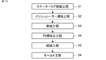
- 4 is a flow chart explaining a manufacturing process of the stator according to Embodiment 1.
- FIG. FIG. 2 is a perspective view of a stator coupling body to which insulators according to Embodiment 1 are coupled;
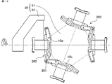
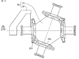
- FIG. 4 is a top view showing a state in which the stator core coupling body of Embodiment 1 is wound by a flyer type winding device;
- FIG. 13 is a top view showing a state in which the same winding device as in FIG.
- FIG. 12 is used to wind a stator core having a different dimension.
- FIG. 13 is a top view showing a state in which the stator core coupled body of the first embodiment is wound by a winding device different from that in FIG. 12 ;
- FIG. 7 is a perspective view showing a state in which the connecting portion is rearranged into a posture in which the connecting portion is assembled to the stator core annular assembly after winding the stator core connected body of Embodiment 1;
- FIG. 16 is a radial rear view of FIG. 15;
- FIG. 4 is a top view showing a state in which semicircular stator core coupling bodies according to Embodiment 1 are coupled;
- FIG. 18 is a perspective view showing a state in which the semicircular stator core coupling body of FIG.
- FIG. 17 is coupled;
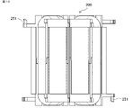
- FIG. 2 is a perspective view of the stator core ring assembly of Embodiment 1;
- FIG. 2 is a perspective view of a stator finished product in which the stator core ring assembly of Embodiment 1 is covered with mold resin;
- 1 is a cross-sectional view of a motor according to Embodiment 1;
- FIG. 8 is a top view of an insulator according to Embodiment 2;
- FIG. 8 is a perspective view of an insulator according to Embodiment 2;
- FIG. 11 is a top view of a stator coupling body in which insulators according to Embodiment 2 are coupled by a first fitting portion;
- FIG. 10 is another top view of the stator connecting portion in which the insulators according to the second embodiment are connected by the first fitting portion;
- FIG. 10 is a top view of a stator connecting portion in which insulators according to Embodiment 2 are connected by a second fitting portion;
- FIG. 11 is a perspective view of an insulator according to Embodiment 3;
- FIG. 28 is a bottom view of the insulator of FIG. 27 as viewed from below in the axial direction;
- FIG. 11 is a perspective view showing a state in which the connecting portion is rearranged to a posture in which the connecting portion is assembled to the stator core ring assembly after winding the stator core connected body according to Embodiment 3;
- FIG. 30 is a perspective view of the state of FIG.
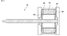
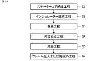
- FIG. 11 is a cross-sectional view of a motor according to Embodiment 4; 10 is a flow chart showing a stator manufacturing process according to Embodiment 4.
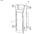
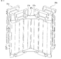
- FIG. FIG. 11 is a perspective view showing a stator core insulation assembly according to Embodiment 5;
- FIG. 11 is a top view showing a state in which a stator core coupling body according to Embodiment 6 is wound by a flyer type winding device.
- FIG. 21 is a perspective view of an insulator according to Embodiment 7;
- FIG. 21 is a perspective view of a separate connecting portion according to Embodiment 7;
- FIG. 21 is a perspective view of a stator coupling body to which insulators according to Embodiment 7 are coupled;
- FIG. 14 is a top view of a stator coupling body to which insulators are coupled according to Embodiment 7;
- FIG. 20 is a perspective view showing a state in which the connecting portion is rearranged to a posture in which the connecting portion is assembled to the stator core annular assembly after winding the stator core connected body of Embodiment 7;
- FIG. 11 is a perspective view of a stator core ring assembly according to Embodiment 7;
- FIG. 21 is a perspective view of another separate connecting portion according to Embodiment 7;
- FIG. 20 is a top view of a stator coupling body in which insulators according to Embodiment 7 are coupled by another separate coupling portion;
- FIG. 20 is a perspective view showing a state in which the insulator according to Embodiment 7 is wound around a stator core coupled body coupled with another separate coupling portion, and then the coupling portion is rearranged into a posture in which the coupling portion is assembled to the stator core ring assembly. .
- a stator core 10 in FIG. 1 is a stator core obtained by dividing an annular stator of an inner rotor type motor (see FIG. 21) by the number of slots, and has teeth portions 11 and a back yoke portion 12 .
- the dividing surface 13, which is the abutting portion with the adjacent teeth, is a simple plane and has no means for joining the stator cores alone. Since the stator core 10 has a simple shape, it suffices to prepare one type of mold for the stator core 10, which facilitates manufacturing.
- FIG. 2 shows a stator core ring assembly 300, which will be described later.
- axial direction (X), circumferential direction ( ⁇ ), and radial direction (R) respectively indicate the directions shown in FIG.
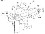
- FIG. 3 is a perspective view of the insulator according to Embodiment 1
- FIG. 4 is a rear view seen from the radially outer peripheral side
- FIG. 5 is a top view seen from the axial direction.
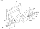
- An insulator 20 for electrically insulating a coil and a stator core shown in FIGS. 3 to 5 has a core fitting portion 21 fitted to the stator core 10 and a winding frame portion 22 for supporting a wound coil.
- the insulator 20 in FIG. 3 shows the upper insulator (see the insulator 20a in FIG. 11) that is fitted from above and below the stator core 10 in the axial direction.
- the winding frame portion 22 has a portion that covers the stator core 10 and an inner peripheral flange portion 23 and an outer peripheral flange portion 24 that protrude in the axial direction. It is supported so that it does not protrude from R (see FIG. 2).
- An introduction groove for introducing the end wire of the coil and a discharge groove for discharging are formed in the outer peripheral flange portion 24 .
- Coupling portions 25 a and 25 b are provided at positions facing the adjacent stator core 10 on the further outer peripheral side of the outer peripheral flange portion 24 , and the coupling portions 25 a and 25 b protrude from the end face of the stator core 10 in the circumferential direction ⁇ .
- a cylindrical columnar portion 251 extending in the axial direction is provided at the tip of the connecting portion 25a, and the connecting portion 25b serves as a guide portion that movably guides the columnar portion 251 of another insulator, as will be described later. have.
- the slot-shaped opening 252 corresponds to this.
- the columnar portion 251 has a shape (notch portion 251a) obtained by cutting out a portion of a cylinder. Since the diameter of the columnar portion 251 is smaller than the width of the connecting portion 25a, a step 253 is formed at the boundary between the columnar portion 251 and the connecting portion 25a. It is desirable that the step 253 is formed along the entire circumference of the columnar portion 251.
- the step 253 is formed in a part of the entire circumference, the step 253 is formed in the axial direction of the stator core 10 when the stator core coupling body 200 described later is formed. It is sufficient that the step 253 is formed at a position that restricts the movement of the .
- the end surface of the columnar portion 251 has a projection 254 projecting outward from the cylindrical surface of the columnar portion 251 .
- a first circular arc portion 252a having the same diameter as the columnar portion 251 is provided on the inlet side of the slot-shaped opening portion 252 of the connecting portion 25b, and is fitted with the columnar portion 251 so that it can freely rotate about the columnar portion 251. It has a structure. That is, the columnar portion 251 is rotatably fitted at the first circular arc portion 252a, which is the fitting portion where the distance between the insulators 20 is the longest.
- a second circular arc portion 252b having the same diameter is also provided on the terminal end side of the opening 252, and the columnar portion 251 is arranged at a position where the second circular arc portion 252b is fitted with the dividing surface 13 of the stator core 10 facing each other.
- the first circular arc portion 252a and the second circular arc portion 252b are connected by a long hole portion 252c that connects the circular arc portions, and the width of the long hole portion 252c is equal to or larger than the diameter of the columnar portion 251.
- the opening 252 consisting of the first circular arc portion 252a, the elongated hole portion 252c, and the second circular arc portion 252b has approximately the same width as the diameter of the columnar portion 251, but as shown in FIGS.
- the first circular arc portion 252a and the second circular arc portion 252b have protrusions 252d for forming a portion having a width smaller than the diameter of the portion 251. As shown in FIG.
- the insulator 20 uses an elastic insulating material such as resin, rubber, paper, or wood. By doing so, the columnar portion 251 can pass through the first circular arc portion 252a and the long hole portion 252c and move to the second circular arc portion 252b.
- the opening side of the second circular arc portion 252b has a surface that fits into the notch portion 251a of the columnar portion 251 . This surface is perpendicular to the direction of removing the columnar portion 251 from the second arcuate portion 252b (the opening direction).
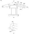
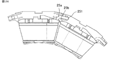
- FIGS. 6 and 7 show a state in which insulators 20 are connected to form stator core connecting body 200 and the connecting portion is assembled to stator core ring assembly 300 .
- the side surface of the projection 255 on the side of the first circular arc portion 252a is positioned to contact the end surface of the long hole portion 252c on the side of the first circular arc portion 252a when the columnar portion 251 is fitted to the second circular arc portion 252b.
- has a guide taper such that the height of the protrusion 255 decreases toward the column 251. As shown in FIG. Due to this shape, the holding force in the connected state can be strengthened.
- the columnar portion 251 can fix the adjacent insulator 20 and stator core 10 at a predetermined angle at the second arc portion 252b, which is the fitting portion where the distance between the insulators 20 is the shortest. can.
- the fitting between the columnar portion 251 and the first circular arc portion 252a or the second circular arc portion 252b is a snap-fit shape utilizing elastic deformation of the insulator, so that assembly can be easily performed.
- the snap fit is attachable and detachable in a plane perpendicular to the axial direction.
- FIG. 7 shows one of the insulators transparently in order to explain the fitted state.
- the inner peripheral flange portion 23 has inner peripheral flange fitting portions 23a and 23b on the circumferential end faces thereof to be fitted with the adjacent insulators 20.
- the inner peripheral collar fitting portions 23a and 23b have a claw-like shape that opens in the axial direction when viewed from the inner peripheral side, and the radial movement of the insulator 20 is restricted between the inner peripheral collar fitting portions 23a and 23b. do not do.
- FIG. 9 is a view of FIG. 8 viewed from the axially lower side to the upper side.
- a winding frame portion 22 obtained by axially dividing the insulator 20 into two has wrap portions 22a and 22b where the insulators overlap each other.
- the wrap portions 22 a and 22 b have the function of increasing the insulation distance between the stator core 10 and the coils 30 .
- the wrap portions 22a and 22b are stepped, and the direction of the step is the same between the wrap portion 22a on one side and the wrap portion 22b on the other side in the circumferential direction. That is, the insulator 20 has a shape in which the step on one axial end side and the step on the other axial end side are fitted to each other on one side or the other side in the circumferential direction.
- stator core insulation step S1 As shown in FIG. 11, two insulators 20 (insulator 20a, insulator 20b) shown in FIG. 3 are assembled to one stator core 10 shown in FIG. An opening 252 (first circular arc portion 252a) of the other insulator 20b faces the axially opposite side of the columnar portion 251 of one insulator 20a. can be assembled to form the stator core insulation assembly 100 .
- the columnar portion 251 and the opening 252 should be arranged to face each other in the axial direction.
- the stepped shape of the wrap portions 22a and 22b of the insulator 20 is oriented in the same direction on one side and the other side in the circumferential direction, so that the insulators 20a and 20b are rotationally symmetrical with each other.
- the other insulator 20b can be formed, and the stator core insulation assembly 100 can be configured with the insulator 20 having the same shape.
- These wrap portions 22a and 22b may or may not be required depending on the insulation specifications of the stator. It is sufficient if the requirements of 23a and 23b are satisfied.
- ⁇ Insulator connection step S2> As shown in FIG. 11 , a plurality of stator core insulation assemblies 100 are connected by fitting columnar portions 251 and first arc portions 252 a of insulators 20 a and 20 b to form stator core connected body 200 . Since the stator core connecting body 200 is connected to the columnar portion 251 by the first arcuate portion 252a, it can freely rotate around the columnar portion 251 as described above. A step 253 formed by the columnar portion 251 and the connecting portion 25 a enters the axial gap between the adjacent stator core 10 and the opening 252 , thereby restricting the axial movement of the opening 252 . A protrusion 254 provided on the end surface of the columnar portion 251 restricts movement in the direction opposite to the restriction by the step 253 .
- the stator core coupling body 200 is mounted on the core gripping mechanism 51 of the winding device 50 and wound. Since the stator core connecting body 200 can be freely rotated about the columnar portion 251, the winding device 50 is rotated to a position where the stator core 10b adjacent to the stator core 10a to be wound does not interfere with the flyer 52. It can be gripped by the core gripping mechanism 51 . Further, as shown in FIG. 13, even stator cores 10c having different dimensions can be wound by the same winding device 50 by aligning the positions of the columnar portions 251 of the insulators.
- the nozzle 53 is brought closer to the stator cores 10a and 10b and moved in a rectangular orbit for winding.
- a stator core 10c with different dimensions from the stator core 10a can be wound with the gripping mechanism.
- the diameter of the nozzle 53 can be increased, and the curvature of the fillet shape connecting the inner periphery of the nozzle 53 to the outlet can be increased, thereby suppressing deterioration of the coil coating. be able to.
- the inner peripheral flange fitting portions 23a and 23b provided in the inner peripheral flange portion 23 described with reference to FIG. Auxiliary hindrance. This is intended to enhance the holding force after the stator core 10 is assembled into a ring. Since the inner peripheral flange fitting portions 23a and 23b have a shape that does not restrict the movement of the insulator in the radial direction (same cross-sectional shape in the radial direction), they do not hinder the radial alignment of the connecting portions 25a and 25b on the outer peripheral side.
- the stator core ring assembly 300 does not require equipment such as a welding device or a press-fitting device and can be easily assembled. Since it is not easily disassembled, no special tools are required for transportation to subsequent processes.
- ⁇ Molding step S6> The wound and connected stator core ring assembly 300 is placed in a resin molding die and molded. As a result, a stator as shown in FIG. 20 is completed (only the outline is shown so that the mold resin is transparent). As shown in FIG. 21, the stator core 10 is pressurized radially inward by the pressure of the resin 400 during molding, so that the divided surfaces 13 of the stator core are butted together to form a magnetic circuit.
- a motor 70 as shown in FIG. 21 can be obtained by incorporating a rotor 60 with bearings attached to both sides in the axial direction into the stator produced by the above steps and fitting brackets.
- stator cores of different shapes can be wound without modification or recombination of the winding machine, the divided stator cores can be easily connected and assembled into an annular shape, and can be divided in the axial direction.
- Some or all of the insulators can have a common shape.
- the distance between adjacent insulators can be variably adjusted, and multiple types of stator cores can be wound without changing the manufacturing equipment, and high-performance stators and motors can be obtained. Therefore, in the stator and the motor, the windings can be wound at high density without increasing the number of parts and the manufacturing process.
- the connecting portion is arranged outside the outer diameter of the stator core, and the yoke portion is partially thinned so that the adjacent yoke portions of the stator core do not interfere with each other during the winding. I had to reduce efficiency.
- the present embodiment it is possible to obtain a stator and a motor that can secure the magnetic path of the stator core.
- the connecting portion 25b may be formed by connecting two arm-shaped portions 25b1 and 25b2 extending in parallel with each other with a connecting portion 25b3.
- a protrusion 252d is formed on the arm-shaped portions 25b1 and 25b2, and a first fitting portion 25b4 and a second fitting portion 25b4 having the same functions as the first arc portion 252a and the second arc portion 252b described in the first embodiment.
- a fitting portion 25b5 is formed.
- the connecting portion 25b3 may be formed at the bottoms of the two arm-like portions 25b1 and 25b2 so as not to hinder the movement of the columnar portion 251 between the first fitting portion 25b4 and the second fitting portion 25b5.
- insulators 20a and 20b having the same shape are assembled on opposite sides in the axial direction to form a stator core insulator.
- the positions of the bottom portions are also reversed, and the connecting portion 25b3 is formed above the two arm portions 25b1 and 25b2.
- the columnar portion 251 of the connecting portion 25a of the present embodiment does not have a cylindrical shape as in the first embodiment, but has a polygonal shape such as a hexagonal column.
- the first fitting portion 25 b 4 and the second fitting portion 25 b 5 are shaped along the outer periphery of the columnar portion 251 .
- the shape of the first fitting portion 25b4 is based on a shape that is graphically congruent or similar to the shape of the columnar portion 251, and fits at a plurality of predetermined angles. , a triangular groove 25b7 that engages with the corners of the polygonal shape and locks the rotation may be formed.
- the columnar portion 251 can fix the adjacent insulator 20 and stator core 10 at a predetermined angle at the second fitting portion 25b5 where the distance between the insulators 20 is the shortest.
- the fitting between the columnar portion 251 and the first fitting portion 25b4 or the second fitting portion 25b5 is a snap-fit shape utilizing elastic deformation of the insulator, so that assembly can be easily performed.
- the snap fit is attachable and detachable in a plane perpendicular to the axial direction.
- FIG. 24 shows the stator core by fitting the columnar portion 251 and the first fitting portion 25b4 in the insulator connection step of the present embodiment.
- This is a state after a plurality of insulation assemblies 100 are connected, mounted on a core gripping mechanism 51 as a stator core connection body 200 by a winding process, and wound.
- the insulator 20 is rotated in a state where the polygonal shape of the columnar portion 251 is fitted in the first fitting portion 25b4, the opening of the first fitting portion 25b4 is elastically deformed and rotated by a rotational load above a certain level. can. As a result, it functions as an auxiliary mechanism for selectively holding the angle of the core during the winding process.
- the process for forming the connecting portion of the wound stator core connecting body 200 into the stator core ring assembly 300 is performed. 25 and 26.
- FIG. 251 By rotating the columnar portion 251 fitted in the first fitting portion 25b4 from the state shown in FIG. 24 to achieve the state shown in FIG. 26, the columnar portion 251 rides over the projection 252d and fits into the second fitting portion 25b5.
- the connecting portions 25a and 25b By forming the connecting portions 25a and 25b in the shape of the present embodiment, the distance between the insulators 20 is the longest at the first fitting portion 25b4 and the closest second fitting portion 25b5. The generated strain can be made equal. Further, as in the first embodiment, since the connecting portions 25a and 25b of the insulator 20 are housed inside the outer diameter of the stator core 10, it is possible to ensure the thickness of the mold resin, which will be described later.
- Embodiment 3 As shown in FIGS. 27 and 28, the long side of the elongated hole portion 252c of the insulator 20 is a tangent line to the arc of the second arc portion 252b, and when the stator core coupling body 200 is formed, the second arc portion 252b is formed. It does not have a holding means that restricts the movement in the circumferential direction by For this reason, an engaging portion 256 is provided on the side surface of the connecting portions 25a and 25b. When combined with adjacent stator cores 10a, 10b as in FIG. 29, FIG. It is provided at a position that catches with 256 and restricts the movement of the insulator and the stator core insulation assembly in the circumferential direction. As shown in FIG. 27, the anchoring portions 256 of adjacent insulators have portions that protrude with respect to the connecting portions 25a, 25b. One or both of the locking portions 256 are notched opposite the protruding portion to facilitate elastic deformation during insertion.
- the engaging portions 256 By having the engaging portions 256 that are elastically deformable on the side surfaces of the connecting portions 25a and 25b, the engaging portions 256 restrict the movement of the stator cores 10a and 10b in the circumferential direction, and the elongated hole portions 252c allow the stator cores 10a and 10b to move. Regulate radial movement.
- the second arc portion 252b has the same size as the first arc portion 252a. Can be configured together.
- the retaining portion 256 of the present embodiment can be added to the shape of the first embodiment. By forming such an engaging portion 256, it is intended to increase the holding force after the stator core 10 is assembled into an annular shape.
- Embodiment 4 As in the motor 70 of FIG. 31, the frame 80 is used instead of the resin 400 for the final fixation of the stator core 10 .
- the material of the frame 80 is, for example, a metal such as iron or aluminum, or a structural material such as reinforced plastic.
- the frame 80 has a cylindrical shape, and the inner diameter of the frame is smaller than the outer diameter of the stator core coupling body.
- the connecting portions 25a and 25b of the insulator 20 are accommodated inside the outer diameter of the stator core 10, so that the insulator can be prevented from interfering with the frame during assembly.
- the method of assembling the frame 80 to the stator is the frame press-fitting or shrink-fitting step S7 in FIG.
- Embodiment 5 As shown in FIG. 33, without dividing the insulator 20 in the axial direction, the stator core 10 is put into a resin mold and insert-molded. As a result, the insulation distance can be secured without considering the step of the wrap portion. If there is a stepped portion at the lap portion, the thin side of the stepped portion needs to be the minimum thickness for resin molding, and the thickness of the insulator at the portion without the lap portion is twice the minimum thickness. On the other hand, since there is no wrap portion in this embodiment, the thickness of the insulator can be made the minimum thickness for resin molding, the space for housing the coil can be increased, and the copper loss of the stator can be reduced.
- stator core insulation assemblies 100 are connected in numbers exceeding one stator to form stator core connected bodies 200, which are attached to a plurality of core gripping mechanisms 51, whereby the coils of each phase are A plurality of flyers 52 are used to continuously wind an electric wire without cutting it in the middle.
- the stator core insulation assembly 100 can be supplied one by one during the winding, thereby eliminating waiting time for workpiece supply and improving the operating rate.
- FIG. 34 shows a configuration in which two out-of-phase coils are arranged between in-phase coils, such as a 9-pole, 12-slot configuration, two in-phase coils, such as a 10-pole, 12-slot configuration, are arranged next to each other. , even if two pairs of out-of-phase coils are interposed between two pairs of in-phase coils, a similar configuration can be obtained by changing the number of stator cores between different flyers to an appropriate number.
- Embodiment 7 The connecting portions 25a and 25b of Embodiments 1 to 5 are provided in the insulator 20, but in the present embodiment, a separate connecting portion is provided separately from the insulator.
- FIG. 35 is a perspective view of insulator 20 of this embodiment.
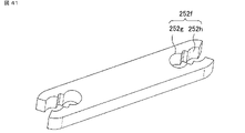
- FIG. 36 is a perspective view of the separate connecting portion 25c.
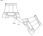
- the insulator 20 has protrusions 27a and 27b formed with columnar portions 26a and 26b. Openings 252e and 252f are formed in the separate connecting portion 25c, and as shown in FIG. 37, the columnar portion 26b formed in the protrusion 27b of the insulator 20a and the opening 252e of the separate connecting portion 25c are separated.
- the columnar portion 26a formed on the projecting portion 27a of the insulator 20b adjacent to the insulator 20a and the opening portion 252f of the separate connecting portion 25c are fitted to each other so as to be rotatably connected.
- a stator core connecting body 200 that can freely rotate around the columnar portions 26a and 26b is constructed, as in FIG. 12 or 34, the core gripping mechanism 51 of the winding device 50 is rotated to a position where the stator core adjacent to the stator core to be wound does not interfere with the flyer 52. , and can be wound by the winding device 50 .
- the connecting portion of the wound stator core connecting body 200 is set in a posture to be assembled with the stator core annular ring assembly 300, and connected so as to form an annular shape as shown in FIG.
- the separate connecting portion 25c of the insulator 20 may be configured to fit inside the outer diameter of the stator core 10, and with such a configuration, the thickness of the mold resin is reduced as in the first embodiment. can be secured.
- the separate connecting portion 25c has an opening and the insulator 20 has two columnar portions.
- the separate connecting portion 25c is rotatably connected to both of the two columnar portions 26a and 26b, one of them may be rotatably connected.
- the openings 252e and 252f formed in the separate connecting portion 25c may have a third arc portion 252g and a fourth arc portion 252h.
- the separate connecting portion 25c can be accommodated within the outer diameter of the core in the state of the stator core ring assembly 300. High-density winding is possible with the same assembly method.
- the fitting portion where the columnar portions 26a and 26b of the insulator 20 and the opening portions 252e and 252f of the separate connecting portion 25c are rotatably connected can be arranged at an arbitrary position with respect to the insulator and the stator core, As in the first embodiment, a plurality of types of stator cores can be wound without changing manufacturing equipment, and a high-performance stator and motor can be obtained. As a result, in the stator and the motor, the windings can be wound at high density without increasing the number of parts and the manufacturing process.
- the motor 70 which is a rotating electric machine, may be manufactured by the method described in the first embodiment or the third embodiment.
Landscapes
- Engineering & Computer Science (AREA)
- Power Engineering (AREA)
- Manufacturing & Machinery (AREA)
- Iron Core Of Rotating Electric Machines (AREA)
- Insulation, Fastening Of Motor, Generator Windings (AREA)
- Manufacture Of Motors, Generators (AREA)
Priority Applications (2)
| Application Number | Priority Date | Filing Date | Title |
|---|---|---|---|
| JP2023523957A JP7570508B2 (ja) | 2021-05-24 | 2021-12-28 | インシュレーター、ステーター、回転電機、ステーターの製造方法、および回転電機の製造方法 |
| CN202180098058.2A CN117280572A (zh) | 2021-05-24 | 2021-12-28 | 绝缘体、定子、旋转电机、定子的制造方法以及旋转电机的制造方法 |
Applications Claiming Priority (2)
| Application Number | Priority Date | Filing Date | Title |
|---|---|---|---|
| JP2021-086736 | 2021-05-24 | ||
| JP2021086736 | 2021-05-24 |
Publications (1)
| Publication Number | Publication Date |
|---|---|
| WO2022249525A1 true WO2022249525A1 (ja) | 2022-12-01 |
Family
ID=84229723
Family Applications (1)
| Application Number | Title | Priority Date | Filing Date |
|---|---|---|---|
| PCT/JP2021/048900 Ceased WO2022249525A1 (ja) | 2021-05-24 | 2021-12-28 | インシュレーター、ステーター、回転電機、ステーターの製造方法、および回転電機の製造方法 |
Country Status (3)
| Country | Link |
|---|---|
| JP (1) | JP7570508B2 (https=) |
| CN (1) | CN117280572A (https=) |
| WO (1) | WO2022249525A1 (https=) |
Cited By (2)
| Publication number | Priority date | Publication date | Assignee | Title |
|---|---|---|---|---|
| US20210320539A1 (en) * | 2018-08-24 | 2021-10-14 | Minebea Mitsumi Inc. | Motor |
| WO2025004677A1 (ja) * | 2023-06-26 | 2025-01-02 | 川崎重工業株式会社 | 発電機のステータ構造 |
Families Citing this family (1)
| Publication number | Priority date | Publication date | Assignee | Title |
|---|---|---|---|---|
| CN118783669A (zh) * | 2024-08-08 | 2024-10-15 | 苏州成就智能科技有限公司 | 一种低噪音高速电机的转子结构 |
Citations (5)
| Publication number | Priority date | Publication date | Assignee | Title |
|---|---|---|---|---|
| JP2004357491A (ja) * | 2003-05-08 | 2004-12-16 | Asmo Co Ltd | 回転電機のステータ及びその製造方法 |
| JP2013118749A (ja) * | 2011-12-02 | 2013-06-13 | Hitachi Industrial Equipment Systems Co Ltd | 電動機の固定子および永久磁石式回転電機 |
| JP2014161200A (ja) * | 2013-01-28 | 2014-09-04 | Asmo Co Ltd | ブラシレスモータ及びブラシレスモータの製造方法 |
| JP2018027001A (ja) * | 2016-07-28 | 2018-02-15 | 三星電子株式会社Samsung Electronics Co.,Ltd. | ステータ及びブラシレスモータ |
| WO2021033496A1 (ja) * | 2019-08-20 | 2021-02-25 | 三菱電機株式会社 | ステータと回転電機、およびそれらの製造方法 |
Family Cites Families (3)
| Publication number | Priority date | Publication date | Assignee | Title |
|---|---|---|---|---|
| JP3279279B2 (ja) | 1998-06-30 | 2002-04-30 | 三菱電機株式会社 | 鉄心装置 |
| JP4589153B2 (ja) | 2005-03-09 | 2010-12-01 | アスモ株式会社 | 巻線方法、ステータの製造方法、及び巻線機 |
| JP5558903B2 (ja) | 2010-04-28 | 2014-07-23 | アスモ株式会社 | 電機子の製造方法、電機子及びモータ |
-
2021
- 2021-12-28 CN CN202180098058.2A patent/CN117280572A/zh active Pending
- 2021-12-28 WO PCT/JP2021/048900 patent/WO2022249525A1/ja not_active Ceased
- 2021-12-28 JP JP2023523957A patent/JP7570508B2/ja active Active
Patent Citations (5)
| Publication number | Priority date | Publication date | Assignee | Title |
|---|---|---|---|---|
| JP2004357491A (ja) * | 2003-05-08 | 2004-12-16 | Asmo Co Ltd | 回転電機のステータ及びその製造方法 |
| JP2013118749A (ja) * | 2011-12-02 | 2013-06-13 | Hitachi Industrial Equipment Systems Co Ltd | 電動機の固定子および永久磁石式回転電機 |
| JP2014161200A (ja) * | 2013-01-28 | 2014-09-04 | Asmo Co Ltd | ブラシレスモータ及びブラシレスモータの製造方法 |
| JP2018027001A (ja) * | 2016-07-28 | 2018-02-15 | 三星電子株式会社Samsung Electronics Co.,Ltd. | ステータ及びブラシレスモータ |
| WO2021033496A1 (ja) * | 2019-08-20 | 2021-02-25 | 三菱電機株式会社 | ステータと回転電機、およびそれらの製造方法 |
Cited By (3)
| Publication number | Priority date | Publication date | Assignee | Title |
|---|---|---|---|---|
| US20210320539A1 (en) * | 2018-08-24 | 2021-10-14 | Minebea Mitsumi Inc. | Motor |
| US11996735B2 (en) * | 2018-08-24 | 2024-05-28 | Minebea Mitsumi Inc. | Motor |
| WO2025004677A1 (ja) * | 2023-06-26 | 2025-01-02 | 川崎重工業株式会社 | 発電機のステータ構造 |
Also Published As
| Publication number | Publication date |
|---|---|
| JPWO2022249525A1 (https=) | 2022-12-01 |
| CN117280572A (zh) | 2023-12-22 |
| JP7570508B2 (ja) | 2024-10-21 |
Similar Documents
| Publication | Publication Date | Title |
|---|---|---|
| WO2022249525A1 (ja) | インシュレーター、ステーター、回転電機、ステーターの製造方法、および回転電機の製造方法 | |
| JP3623702B2 (ja) | 回転電機用ステータ | |
| WO2002084842A1 (fr) | Stator pour moteurs a rotor interne et procede de production | |
| AU2016284404B2 (en) | Rotating electrical machine stator, rotating electrical machine, rotating electrical machine stator production method | |
| WO2017141562A1 (ja) | 回転電機の固定子、回転電機、および、回転電機の固定子の製造方法 | |
| WO2020174817A1 (ja) | 回転電機のステータ、回転電機、回転電機のステータの製造方法、および、回転電機の製造方法 | |
| JP3430109B2 (ja) | 内転型電動機の固定子 | |
| CN113039704B (zh) | 定子及使用该定子的电动机 | |
| JPH07245895A (ja) | 回転電動機およびその製造方法 | |
| JP7481582B2 (ja) | 固定子、回転電機、固定子の製造方法および回転電機の製造方法 | |
| JP4297929B2 (ja) | モータ及びモータの製造方法 | |
| WO2020067250A1 (ja) | ステータ、モータおよびステータの製造方法 | |
| WO2018180345A1 (ja) | 電動モータ用ステータおよび電動モータ | |
| US11201511B2 (en) | Stator for electric motor and electric motor | |
| EP4044402B1 (en) | Motor | |
| CN118826344A (zh) | 电机、用于电机的定子以及用于制造这样的定子的方法 | |
| JP7621862B2 (ja) | モータ | |
| JP2002204555A (ja) | コンデンサ電動機固定子およびその製造方法 | |
| JP7479230B2 (ja) | ステータコア、回転電機のステータ、回転電機、回転電機のステータの製造方法、および回転電機の製造方法 | |
| US20250119020A1 (en) | Insulator, stator, rotating electric machine, and method for manufacturing stator | |
| JP7147745B2 (ja) | 電動モータ用ステータおよび電動モータ | |
| JP4166780B2 (ja) | 内転型電動機の固定子 | |
| JP7819216B2 (ja) | 回転電機のステータ、回転電機、回転電機のステータの製造方法および回転電機の製造方法 | |
| JP7790037B2 (ja) | モータ | |
| JP7481583B2 (ja) | 固定子、回転電機、固定子の製造方法および回転電機の製造方法 |
Legal Events
| Date | Code | Title | Description |
|---|---|---|---|
| 121 | Ep: the epo has been informed by wipo that ep was designated in this application |
Ref document number: 21943158 Country of ref document: EP Kind code of ref document: A1 |
|
| ENP | Entry into the national phase |
Ref document number: 2023523957 Country of ref document: JP Kind code of ref document: A |
|
| WWE | Wipo information: entry into national phase |
Ref document number: 202180098058.2 Country of ref document: CN |
|
| NENP | Non-entry into the national phase |
Ref country code: DE |
|
| 122 | Ep: pct application non-entry in european phase |
Ref document number: 21943158 Country of ref document: EP Kind code of ref document: A1 |