WO2022249274A1 - Compresseur - Google Patents
Compresseur Download PDFInfo
- Publication number
- WO2022249274A1 WO2022249274A1 PCT/JP2021/019768 JP2021019768W WO2022249274A1 WO 2022249274 A1 WO2022249274 A1 WO 2022249274A1 JP 2021019768 W JP2021019768 W JP 2021019768W WO 2022249274 A1 WO2022249274 A1 WO 2022249274A1
- Authority
- WO
- WIPO (PCT)
- Prior art keywords
- spiral tooth
- fixed
- thick
- oscillating
- wall
- Prior art date
Links
- 238000007906 compression Methods 0.000 claims abstract description 46
- 230000006835 compression Effects 0.000 claims abstract description 45
- 238000007789 sealing Methods 0.000 claims description 2
- 239000003507 refrigerant Substances 0.000 description 50
- 239000003921 oil Substances 0.000 description 21
- 238000010586 diagram Methods 0.000 description 17
- 230000002093 peripheral effect Effects 0.000 description 17
- 238000005057 refrigeration Methods 0.000 description 8
- 238000004804 winding Methods 0.000 description 8
- 238000001816 cooling Methods 0.000 description 7
- 238000010438 heat treatment Methods 0.000 description 7
- 239000007788 liquid Substances 0.000 description 6
- 230000014759 maintenance of location Effects 0.000 description 4
- 230000007423 decrease Effects 0.000 description 3
- 210000000078 claw Anatomy 0.000 description 2
- 230000000593 degrading effect Effects 0.000 description 2
- 230000006866 deterioration Effects 0.000 description 2
- 239000000470 constituent Substances 0.000 description 1
- 239000010721 machine oil Substances 0.000 description 1
- 239000000463 material Substances 0.000 description 1
- 238000000034 method Methods 0.000 description 1
- 230000010355 oscillation Effects 0.000 description 1
- 230000000717 retained effect Effects 0.000 description 1
- 238000003466 welding Methods 0.000 description 1
Images


Classifications
-
- F—MECHANICAL ENGINEERING; LIGHTING; HEATING; WEAPONS; BLASTING
- F04—POSITIVE - DISPLACEMENT MACHINES FOR LIQUIDS; PUMPS FOR LIQUIDS OR ELASTIC FLUIDS
- F04C—ROTARY-PISTON, OR OSCILLATING-PISTON, POSITIVE-DISPLACEMENT MACHINES FOR LIQUIDS; ROTARY-PISTON, OR OSCILLATING-PISTON, POSITIVE-DISPLACEMENT PUMPS
- F04C18/00—Rotary-piston pumps specially adapted for elastic fluids
- F04C18/02—Rotary-piston pumps specially adapted for elastic fluids of arcuate-engagement type, i.e. with circular translatory movement of co-operating members, each member having the same number of teeth or tooth-equivalents
Definitions
- the present disclosure relates to a compressor that compresses refrigerant.
- a scroll compressor is known as a compressor used in air conditioners, refrigerators, etc. to compress refrigerant.
- a scroll compressor has a container, and a compression mechanism portion that is housed in the container and compresses a refrigerant in a compression chamber that is formed by combining a fixed scroll and an orbiting scroll.
- the fixed scroll is provided with fixed spiral teeth on a fixed base plate
- the oscillating scroll is provided with oscillating spiral teeth on an oscillating base plate.
- the compression chamber is formed by meshing fixed spiral teeth and oscillating spiral teeth.
- the oscillating movement of the oscillating scroll reduces the volume of the compression chamber and changes the position of the compression chamber, thereby sucking and compressing the refrigerant.
- a scroll compressor generally contacts the tip of one spiral tooth and the bottom of the other spiral tooth.
- a difference in the amount of thermal expansion of the spiral tooth occurs due to the temperature difference between the winding start and the winding end of the spiral tooth.
- the spiral tooth deforms due to a change in the load acting on the back surface of the spiral tooth.
- minute gaps are formed at the tips of the spiral teeth, and compressed gas such as refrigerant may leak in the compression chamber.
- Patent Literature 1 discloses a scroll compressor in which spiral teeth are processed in advance so that the height of the spiral teeth becomes lower toward the center. Patent document 1 attempts to align the heights of the spiral teeth after thermal expansion.
- Patent Document 2 discloses a scroll compressor in which side walls forming grooves for holding tip seals are provided only on the outside of spiral teeth. Patent document 2 attempts to secure a contact area by reducing the tooth thickness.
- Patent Document 2 has a problem with the retention of the tip seal.
- the present disclosure has been made to solve the above problems, and aims to provide a compressor that improves the retention of the tip seal while ensuring the contact area.
- a compressor includes a container forming an outer shell, an electric mechanism provided inside the container, a main shaft attached to the electric mechanism and transmitting a rotational force of the electric mechanism, and fixed inside the container.
- a fixed scroll provided on the fixed base plate and having fixed spiral teeth flattened in one direction; a rocking base plate connected to the upper end of the main shaft; and an oscillating scroll having an oscillating spiral tooth flattened in one direction to form a compression chamber together with the fixed spiral tooth, and a fixed chip seals for sealing between the spiral tooth and the oscillating bedplate and between the oscillating spiral tooth and the fixed bedplate, overlapping the major axis at the stationary spiral tooth and overlapping the major axis at the oscillating spiral tooth.
- the thick portion is provided at the outer end in the width direction of the upper end face and extends away from the upper end face
- the thick outer wall is provided at the inner end in the width direction of the upper end face and extends away from the upper end face. and a thick inner wall forming a thick groove between the thick outer wall and into which the tip seal is inserted.
- the fixed spiral tooth and the oscillating spiral tooth are flattened in one direction, and the portion of the fixed spiral tooth that overlaps with the major axis and the portion of the oscillating spiral tooth that overlaps with the major axis becomes the thick portion.
- a sufficient contact area can be secured in the thick portion.
- a tip seal is inserted into a thick groove formed between a thick outer wall and a thick inner wall of the thick portion. That is, since the thick outer wall and the thick inner wall are provided on both sides of the tip seal, the tip seal is highly retainable. In this way, it is possible to improve the retention of the tip seal while ensuring the contact area.
- FIG. 1 is a circuit diagram showing a refrigeration cycle apparatus according to Embodiment 1;
- FIG. 1 is an axial sectional view showing a compressor according to Embodiment 1;
- FIG. 1 is a circumferential cross-sectional view showing a compressor according to Embodiment 1;
- FIG. 4 is a diagram showing rotation phases of an orbiting scroll of the compressor according to Embodiment 1.
- FIG. FIG. 5 is a diagram showing the state of the oscillating spiral tooth according to Embodiment 1;
- 1 is an axial sectional view showing a compressor according to Embodiment 1;
- FIG. FIG. 4 is a schematic diagram showing a thick portion and a thin portion according to Embodiment 1;
- FIG. 7 is a circumferential cross-sectional view showing a compressor according to Embodiment 2;
- FIG. 10 is a diagram showing a state of an oscillating spiral tooth according to Embodiment 2;
- FIG. 11 is a circumferential cross-sectional view showing a compressor according to Embodiment 3;
- FIG. 1 is a circuit diagram showing a refrigeration cycle apparatus 100 according to Embodiment 1.
- the refrigeration cycle device 100 is, for example, an air conditioner that adjusts air in an indoor space, and includes an outdoor unit 102 and an indoor unit 103 as shown in FIG.
- the outdoor unit 102 is provided with, for example, a compressor 1 , a channel switching device 107 , an outdoor heat exchanger 108 , an outdoor fan 109 and an expansion section 110 .
- the indoor unit 103 is provided with, for example, an indoor heat exchanger 111 and an indoor fan 112 .
- the refrigeration cycle device 100 is not limited to an air conditioner, and may be a refrigerator.
- a refrigerant circuit 104 is configured by connecting the compressor 1 , the flow switching device 107 , the outdoor heat exchanger 108 , the expansion section 110 and the indoor heat exchanger 111 by refrigerant pipes 105 .
- the compressor 1 sucks a low-temperature, low-pressure refrigerant, compresses the sucked refrigerant, converts it into a high-temperature, high-pressure refrigerant, and discharges it.
- the compressor 1 is, for example, a capacity-controllable inverter compressor.
- the channel switching device 107 switches the direction in which the refrigerant flows in the refrigerant circuit 104, and is, for example, a four-way valve.
- the outdoor heat exchanger 108 exchanges heat, for example, between outdoor air and refrigerant.
- the outdoor heat exchanger 108 acts as a condenser during cooling operation and acts as an evaporator during heating operation.
- the expansion unit 110 is a pressure reducing valve or an expansion valve that reduces the pressure of the refrigerant to expand it.
- the expansion part 110 is, for example, an electronic expansion valve whose opening is adjusted.
- the indoor heat exchanger 111 exchanges heat, for example, between indoor air and refrigerant.
- the indoor heat exchanger 111 acts as an evaporator during cooling operation, and acts as a condenser during heating operation.
- the indoor fan 112 is a device that sends indoor air to the indoor heat exchanger 111 .
- cooling operation Next, operation modes of the refrigeration cycle apparatus 100 will be described.
- the cooling operation the refrigerant sucked into the compressor 1 is compressed by the compressor 1 and discharged in a high-temperature and high-pressure gas state.
- the high-temperature and high-pressure gaseous refrigerant discharged from the compressor 1 passes through the flow switching device 107 and flows into the outdoor heat exchanger 108 acting as a condenser. It is heat-exchanged with outdoor air sent by 109 to condense and liquefy.
- the condensed liquid refrigerant flows into the expansion section 110 and is expanded and decompressed in the expansion section 110 to become a low-temperature, low-pressure gas-liquid two-phase refrigerant. Then, the gas-liquid two-phase refrigerant flows into the indoor heat exchanger 111 acting as an evaporator, and in the indoor heat exchanger 111, heat is exchanged with the indoor air sent by the indoor blower 112 to evaporate and gasify. do. At this time, the indoor air is cooled, and cooling is performed in the room. The vaporized low-temperature, low-pressure gaseous refrigerant passes through the flow path switching device 107 and is sucked into the compressor 1 .
- the heating operation In the heating operation, the refrigerant sucked into the compressor 1 is compressed by the compressor 1 and discharged in a high-temperature and high-pressure gas state.
- the high-temperature and high-pressure gaseous refrigerant discharged from the compressor 1 passes through the flow path switching device 107 and flows into the indoor heat exchanger 111 acting as a condenser. It is heat-exchanged with the room air sent by 112 to condense and liquefy. At this time, the indoor air is warmed, and heating is performed in the room.
- the condensed liquid refrigerant flows into the expansion section 110 and is expanded and decompressed in the expansion section 110 to become a low-temperature, low-pressure gas-liquid two-phase refrigerant. Then, the gas-liquid two-phase refrigerant flows into the outdoor heat exchanger 108 acting as an evaporator, where it is heat-exchanged with the outdoor air sent by the outdoor blower 109 to evaporate and gasify. do.
- the vaporized low-temperature, low-pressure gaseous refrigerant passes through the flow path switching device 107 and is sucked into the compressor 1 .
- the refrigeration cycle device 100 does not have to have the channel switching device 107 . In this case, the refrigeration cycle device 100 becomes a dedicated cooling machine or a dedicated heating machine.
- FIG. 2 is an axial sectional view showing the compressor 1 according to Embodiment 1.
- the compressor 1 sucks and compresses the refrigerant circulating in the refrigerant circuit 104, for example, and discharges the refrigerant in a high-temperature and high-pressure state, and is, for example, a hermetic scroll compressor.
- the compressor 1 includes a container 2, a frame 14, a sub-frame 16, a main shaft 30, a main bearing 17, a sub-bearing 18, a suction pipe 51, a discharge pipe 52, a compression and a mechanism section 10 .
- the compressor 1 also includes an Oldham ring 40 , an oil pump 19 , and an electric mechanism section 20 .
- the container 2 is a closed container that constitutes the outer shell of the compressor 1 and has a cylindrical shape. Inside the container 2, the compression mechanism section 10, the electric mechanism section 20, and other parts are accommodated. Inside the container 2, the compression mechanism section 10 is arranged above and the electric mechanism section 20 is arranged below. A bottom portion 43 of the container 2 is formed with an oil reservoir portion 2a that stores refrigerating machine oil.
- the frame 14 is fixed to the container 2 and accommodates the compression mechanism section 10, and rotatably supports the main shaft 30 via main bearings 17, for example.
- the frame 14 is arranged above the electric mechanism portion 20 and positioned between the electric mechanism portion 20 and the compression mechanism portion 10 .
- a discharge pipe 52 is connected to the inside of the frame 14 . The compressed refrigerant passes through the frame 14 and is discharged from the discharge pipe 52 .
- the subframe 16 is arranged below the electric mechanism section 20 inside the container 2 .
- the subframe 16 rotatably supports the main shaft 30 via the subbearing 18 .
- the frame 14 and the sub-frame 16 are fixed inside the container 2 so as to face each other with the electric mechanism section 20 interposed therebetween.
- the frame 14 and subframe 16 are fixed to the inner peripheral surface of the container 2 by shrink fitting, welding, or the like.
- the main shaft 30 is supported by the frame 14 at the center of the container 2 and is a rod-shaped crankshaft extending vertically, and connects the electric mechanism section 20 and the compression mechanism section 10 .
- the main shaft 30 connects the electric mechanism portion 20 and the compression mechanism portion 10 to transmit the rotational force of the electric mechanism portion 20 to the compression mechanism portion 10 .
- a rocking bed plate 12 a of the rocking scroll 12 is provided at the upper end of the main shaft 30 .
- the main shaft 30 has an eccentric shaft portion 31 and a main shaft portion 30a.
- the eccentric shaft portion 31 is eccentric with respect to the axis of the main shaft 30 and is rotatably accommodated in the rocking bearing 15 .
- the outer peripheral portion of the eccentric shaft portion 31 is in close contact with the inner peripheral portion of the swing bearing 15 via the refrigerator oil.
- the main shaft portion 30 a is supported by a main bearing 17 provided on the frame 14 .
- a rotor of the electric mechanism portion 20 is fixed to the main shaft portion 30a by shrink fitting or the like.
- An oil passage 32 through which oil passes is formed inside the main shaft 30 .
- the main bearing 17 is provided in the central portion of the frame 14 and supports the upper portion of the main shaft 30 so as to be rotatable.
- the sub-bearing 18 is press-fitted into the central portion of the sub-frame 16 and supports the lower portion of the main shaft 30 so as to be rotatable.
- the suction pipe 51 is connected to the first space 72 formed in the fixed scroll 11 of the compression mechanism section 10 on the side of the container 2 .
- the suction pipe 44 sucks the low-pressure refrigerant flowing from the refrigerant pipe 105 into the first space 72 .
- the discharge pipe 52 is connected to the space formed in the frame 14 on the side of the container 2 .
- the discharge pipe 52 discharges the high-pressure refrigerant compressed by the compression mechanism section 10 to the refrigerant pipe 105 outside the compressor 1 .
- the compression mechanism section 10 compresses the refrigerant sucked from the suction pipe 51 and discharges it outside the compression mechanism section 10 inside the container 2 .
- the compression mechanism section 10 has a fixed scroll 11 and an orbiting scroll 12 .
- the fixed scroll 11 is fixed to the container 2 above the orbiting scroll 12, and has a fixed base plate 11a and fixed spiral teeth 11b.
- the fixed base plate 11 a is a plate-like member and constitutes the upper surface of the compression mechanism section 10 .
- a discharge port 13 is formed in the central portion of the fixed base plate 11a, and a first space 72 is formed on the side of the fixed base plate 11a.
- the fixed spiral tooth 11b is a spiral protrusion extending downward from the lower surface of the fixed base plate 11a.
- the orbiting scroll 12 has an orbiting base plate 12a and an orbiting spiral tooth 12b.
- the rocking plate 12 a is a plate-like member arranged above the frame 14 .
- the oscillating spiral tooth 12b is a spiral projection extending upward from the upper surface of the oscillating base plate 12a.
- the fixed scroll 11 and the orbiting scroll 12 are provided inside the container 2 with the fixed spiral teeth 11b and the orbiting spiral teeth 12b meshing with each other.
- the fixed spiral tooth 11b and the oscillating spiral tooth 12b are formed following an involute curve.
- a plurality of compression chambers 60 are formed between the teeth 12b.
- a swing bearing 15 is provided between the swing scroll 12 and the eccentric shaft portion 31 .
- the swing bearing 15 covers the main shaft 30 and the eccentric shaft portion 31 and supports the main shaft 30 rotatably.
- the eccentric shaft portion 31 is provided at the upper end of the main shaft 30 and eccentrically rotates the orbiting scroll 12 .
- the Oldham ring 40 is provided on the thrust surface of the orbiting scroll 12 opposite to the surface on which the orbiting spiral teeth 12b are formed.
- the Oldham ring 40 prevents the orbiting scroll 12 from rotating during the eccentric orbiting motion, and allows the orbiting scroll 12 to revolve.
- the upper and lower surfaces of the Oldham's ring 40 are provided with claws (not shown) projecting perpendicularly to each other. The claws of the Oldham ring 40 are inserted into Oldham grooves 41 (see FIG. 3) formed in the orbiting scroll 12 and frame 14 .
- the oil pump 19 is accommodated in the bottom portion 43 of the container 2 and sucks up oil from the oil reservoir portion 2a.
- the oil pump 19 is fixed to the lower portion of the main shaft 30 .
- the oil pump 19 sucks up the oil stored in the oil reservoir 2 a into an oil passage 32 formed inside the main shaft 30 and supplies the oil to the auxiliary bearing 18 , the main bearing 17 and the oscillating bearing 15 through the oil passage 32 .
- the oil pump 19 may be omitted. In this case, for example, a configuration is adopted in which oil is sucked up from the oil reservoir portion 2a using differential pressure.
- the electric mechanism part 20 is provided in the lower part inside the container 2 .
- the electric mechanism section 20 drives the orbiting scroll 12 that constitutes the compression mechanism section 10 . That is, the motor-driven mechanism section 20 rotates the orbiting scroll 12 via the main shaft 30 , thereby compressing the refrigerant in the compression mechanism section 10 .
- the electric mechanism section 20 has a rotor 21 and a stator 22 .
- the rotor 21 is provided inside the stator 22 .
- the rotor 21 is rotationally driven by energizing the stator 22 to rotate the main shaft 30 .
- the rotor 21 is fixed to the outer periphery of the main shaft 30 and held with a small gap from the stator 22 .
- the low-pressure refrigerant flowing out of the indoor heat exchanger 111 is sucked into the first space 72 of the fixed base plate 11 a of the container 2 through the suction pipe 51 .
- the low-pressure refrigerant that has flowed into the first space 72 flows into the second space 73 through two openings (not shown) provided in the frame 14 .
- the low-pressure refrigerant that has flowed into the second space 73 is sucked into the compression chamber 60 as the oscillating spiral tooth 12b oscillates relative to the fixed spiral tooth 11b.
- the compression chamber 60 that has taken in the refrigerant decreases in volume while moving from the outer circumference to the center, thereby compressing the refrigerant.
- the refrigerant is boosted from a low pressure to a high pressure due to the geometric volume change of the compression chamber 60 caused by the relative oscillating motion of the oscillating spiral tooth 12b with respect to the fixed spiral tooth 11b.
- the compressed high-pressure refrigerant passes through the discharge port 13 of the fixed scroll 11 and the through hole 61 a of the baffle 61 , pushes the discharge valve 62 open, and is discharged into the discharge muffler 63 .
- the high-pressure refrigerant discharged into the discharge muffler 63 flows into the third space 74 and is discharged from the compressor 1 through the discharge pipe 52 .
- the third space 74 and the discharge pipe 52 communicate with each other through the frame 14 and the like.
- FIG. 3 is a circumferential cross-sectional view showing the compressor 1 according to Embodiment 1.
- the container 2 has a circular cross section in the circumferential direction, and inside the container 2 , the outer peripheral surface of the frame 14 is fixed in contact with the inner peripheral surface of the container 2 .
- the outer peripheral surface of the frame 14 is also perfectly circular.
- a fixed scroll 11 and an orbiting scroll 12 are arranged in the second space 73 of the frame 14 .
- An Oldham groove 41 in which the Oldham ring 40 is provided is formed in the second space 73 .
- the rocking plate 12a is flattened in one direction.
- the term "flat” includes an oval shape and an elliptical shape, and refers to a shape that is flatter than a circular shape.
- the Oldham's groove 41 is arranged on the short axis side of the rocking plate 12a. Therefore, the rocking rocking plate 12a and the Oldham's groove 41 do not interfere with each other.
- the fixed spiral tooth 11b and the oscillating spiral tooth 12b are flattened in one direction.
- the rocking bed plate 12a is also flat, the space on the rocking bed plate 12a can be effectively utilized by flattening the rocking spiral teeth 12b provided on the rocking bed plate 12a. be able to.
- the volume of the compression chamber 60 can be increased without changing the size of the container 2 . Therefore, the performance of the compressor 1 can be improved. Further, the size of the container 2 can be reduced while maintaining the performance of the compressor 1 .
- spiral teeth when both the fixed spiral tooth 11b and the oscillating spiral tooth 12b are shown without distinction, they are collectively referred to as spiral teeth.
- both the fixed base plate 11a and the rocking base plate 12a are shown without distinction, they are collectively referred to as base plates.
- tip seals 50 are provided above the fixed spiral teeth 11b and above the oscillating spiral teeth 12b.
- the upper portion of the fixed spiral tooth 11b and the upper portion of the oscillating spiral tooth 12b are the tip of the fixed spiral tooth 11b and the tip of the oscillating spiral tooth 12b, respectively.
- the tip seal 50 seals between the fixed spiral tooth 11b and the oscillating base plate 12a and between the oscillating spiral tooth 12b and the fixed base plate 11a.
- the tip seal 50 is inserted into grooves formed in the upper end faces of the fixed spiral tooth 11b and the oscillating spiral tooth 12b. That is, the tip seal 50 is also flattened in one direction like the fixed spiral tooth 11b and the oscillating spiral tooth 12b.
- the degree of flatness of the tip seal 50 may be different from the degree of flatness of the fixed spiral tooth 11b and the oscillating spiral tooth 12b.
- FIG. 4 is a diagram showing the rotational phases of the orbiting scroll 12 of the compressor 1 according to Embodiment 1.
- FIG. FIG. 4(a) shows the positions of spiral teeth at a rotational phase of 0 (2 ⁇ ) [rad]
- FIG. 4(b) shows the positions of spiral teeth at a rotational phase of ⁇ /2 [rad].
- FIG. 4(c) shows the positions of the spiral teeth at the rotational phase of ⁇ [rad]
- FIG. 4(d) shows the positions of the spiral teeth at the rotational phase of 3 ⁇ /2 [rad].
- the compression mechanism section 10 takes in low-temperature gas from the outer peripheral portion of the container 2, gradually compresses it into high-temperature and high-pressure gas, and discharges it from the central portion. For this reason, a temperature difference and a pressure difference occur between the outer peripheral portion at the end of the winding of the fixed spiral tooth 11b and the oscillating spiral tooth 12b and the central portion at the start of winding. As a result, the deformation amounts of the fixed spiral tooth 11b and the oscillating spiral tooth 12b change between the outer peripheral portion and the central portion. Therefore, there is a difference in height between the fixed spiral tooth 11b and the oscillating spiral tooth 12b.
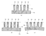
- FIG. 5 is a diagram showing the state of the oscillating spiral tooth 12b according to Embodiment 1.
- FIG. 5(a) is a diagram showing a state in which the oscillating spiral tooth 12b is not deformed
- FIG. 5(b) is a diagram showing a state in which the oscillating spiral tooth 12b is deformed by thermal expansion
- 5(c) is a diagram showing a state in which the rocking base plate 12a supporting the rocking spiral tooth 12b is curved and deformed. As shown in FIG.
- the tip of one spiral tooth and the other spiral tooth A concave gap that widens toward the center is formed between it and the tooth root. At this time, the tip seal 50 floats up to fill the gap, thereby suppressing gas leakage from the compression chamber 60 .
- FIG. 6 is an axial sectional view showing the compressor 1 according to Embodiment 1.
- the fixed spiral tooth 11b and the oscillating spiral tooth 12b have a thickness that increases or decreases, and have a thick portion 81 and a thin portion 91.
- the wall thickness when the rotational phase (extension angle) of the spiral tooth is ⁇ /2 [rad] and 3 ⁇ /2 [rad] than the wall thickness when 0 (2 ⁇ ) [rad] and ⁇ [rad] is thicker. That is, the thick portion 81 is a portion that overlaps the major axis of the fixed spiral tooth 11b and overlaps the major axis of the oscillating spiral tooth 12b.
- the thick portion 81 is a portion whose extension angle is in the range of N ⁇ /4 [rad].
- N is a natural number including 0.
- the thin portion 91 is a portion that overlaps the minor axis of the fixed spiral tooth 11b and the minor axis of the oscillating spiral tooth 12b.
- the thin portion 91 is a portion whose extension angle is in the range of N ⁇ + ⁇ /2 ⁇ /4 [rad].
- the thick portion 81 has a thick outer wall 82 and a thick inner wall 83 .
- the thick outer wall 82 is provided at the outer end portion in the width direction of the upper end surface of the thick portion 81 and extends in a direction away from the upper end surface.
- the thick inner wall 83 is provided at the inner end portion in the width direction of the upper end surface of the thick portion 81 and extends away from the upper end surface.
- a thick groove 84 into which the tip seal 50 is inserted is formed between the thick outer wall 82 and the thick inner wall 83 . That is, the thick portion 81 has outer walls on both sides of the tip seal 50 .
- the thin portion 91 has a thin outer wall 92 .
- the thin outer wall 92 is provided at the outer end portion in the width direction of the upper end surface and extends in a direction away from the upper end surface.
- a thin groove 94 into which the tip seal 50 is inserted is formed between the thin outer wall 92 and the inner end in the width direction. That is, the outer wall is provided only on the outside of the tip seal 50 in the thin portion 91 .
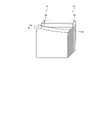
- FIG. 7 is a schematic diagram showing the thick portion 81 and thin portion 91 according to the first embodiment.
- FIG. 7 is a schematic diagram representing the oscillating spiral tooth 12b in a straight line.
- the thick outer wall 82 and the thin outer wall 92 have the same height, but the thick inner wall 83 draws a smooth curved surface toward the thin portion 91 and becomes lower. becomes 0.
- the height of the thick inner wall 83 changes in a constant cycle with respect to the extension angles of the fixed spiral tooth 11b and the oscillating spiral tooth 12b.
- the thick outer wall 82 and the thick inner wall 83 have the same height.
- the thicker one may be thicker than the thin outer wall 92 .
- the circumferential end of the tip seal 50 is installed in the thin portion 91 .
- the rigidity of the end portion of the groove that holds the tip seal 50 can be ensured. Therefore, it is possible to suppress the deterioration of the reliability of the compressor 1 .
- the fixed spiral tooth 11b and the oscillating spiral tooth 12b are flattened in one direction. , and the thick portion 81 .
- a sufficient contact area can be secured in the thick portion 81 .
- a chip seal 50 is inserted into a thick groove 84 formed between a thick outer wall 82 and a thick inner wall 83 of the thick portion 81 . That is, since the thick outer wall 82 and the thick inner wall 83 are provided on both sides of the tip seal 50, the tip seal 50 can be highly retained. In this way, it is possible to improve the retention of the tip seal 50 while ensuring the contact area.
- the thin portion 91 may have a thin inner wall.
- the thin inner wall is provided at the inner end portion in the width direction of the upper end surface of the thin portion 91, extends away from the upper end surface, and is between the outer end portion in the width direction and the thin groove into which the tip seal 50 is inserted. 94.
- the thicker one of the thick outer wall 82 and the thick outer wall 82 may be thicker than the thin inner wall.
- FIG. 8 is a circumferential cross-sectional view showing compressor 1 according to Embodiment 2. As shown in FIG. Embodiment 2 is different from Embodiment 1 in that a tip seal 50 is provided at the central portion of fixed spiral tooth 11b and oscillating spiral tooth 12b.
- the same reference numerals are assigned to the same parts as in the first embodiment, and the description thereof is omitted.
- the tip seal 50 is provided only at the central portion of the fixed spiral tooth 11b and the oscillating spiral tooth 12b, and is not provided at the outer peripheral portion of the fixed spiral tooth 11b and the oscillating spiral tooth 12b. do not have.
- the central portion refers to the portion in which the extension angle is smaller than 3 ⁇ [rad]
- the outer peripheral portion refers to the portion in which the extension angle is greater than 3 ⁇ [rad].
- FIG. 9 is a diagram showing the state of the oscillating spiral tooth 12b according to the second embodiment. Next, shape changes due to temperature changes and load changes acting on the oscillating spiral tooth 12b will be described.
- FIG. 9(a) is a diagram showing a state in which the oscillating spiral tooth 12b is not deformed
- FIG. 9(b) is a diagram showing a state in which the oscillating spiral tooth 12b is deformed by thermal expansion
- 9(c) is a diagram showing a state in which the rocking base plate 12a supporting the rocking spiral tooth 12b is curved and deformed. As shown in FIG.
- the tip seal 50 is provided at the central portion of the fixed spiral tooth 11b and the oscillating spiral tooth 12b. Therefore, the entire surfaces of the tooth tips of the outer peripheral portions of the fixed spiral tooth 11b and the oscillating spiral tooth 12b can be brought into contact with each other. Therefore, the contact surface pressure acting on the tips of the outer peripheral portions of the fixed spiral tooth 11b and the oscillating spiral tooth 12b can be reduced, so that the reliability of the compressor 1 can be further enhanced.
- the circumferential end portion of the tip seal 50 is installed in the thin portion 91 . Thereby, the rigidity of the end portion of the groove that holds the tip seal 50 can be ensured. Therefore, it is possible to suppress the deterioration of the reliability of the compressor 1 .
- FIG. 10 is a circumferential cross-sectional view showing compressor 1 according to Embodiment 3. As shown in FIG. Embodiment 3 differs from Embodiments 1 and 2 in that the tip seal 50 is not provided in the thin portion 91 .
- the same reference numerals are given to the parts that are common to the first and second embodiments, and the description thereof is omitted.
- the tip seal 50 is provided only on the thick portion 81 and not on the thin portion 91 .
- the thick portion 81 has an extension angle of N ⁇ /4 [rad]
- the thin portion 91 has an extension angle of N ⁇ + ⁇ /2 ⁇ /4 [rad]. rad].
- the tip seal 50 is not provided on the thin portion 91 . Therefore, the amount of tip seal 50 used can be reduced. Therefore, the reliability of the compressor 1 can be improved with less material.
- Compressor 2 Container 2a Oil reservoir 10
- Compression mechanism 11 Fixed scroll 11a Fixed base plate 11b Fixed spiral tooth 12 Oscillating scroll 12a Oscillating bedplate 12b Oscillating spiral tooth 13 Discharge Outlet, 14 frame, 15 rocking bearing, 16 sub-frame, 17 main bearing, 18 sub-bearing, 19 oil pump, 20 electric mechanism, 21 rotor, 22 stator, 30 main shaft, 30a main shaft, 31 eccentric shaft , 32 oil passage, 40 Oldham ring, 41 Oldham groove, 50 chip seal, 51 suction pipe, 52 discharge pipe, 60 compression chamber, 61 baffle, 61a through hole, 62 discharge valve, 63 discharge muffler, 72 first space, 73 Second space 74 Third space 81 Thick part 82 Thick outer wall 83 Thick inner wall 84 Thick groove 91 Thin part 92 Thin outer wall 94 Thin groove 100 Refrigeration cycle device 102 Outdoor unit 103 Indoor unit, 104 Refrigerant circuit, 105 Refrigerant pipe, 107
Landscapes
- Engineering & Computer Science (AREA)
- Mechanical Engineering (AREA)
- General Engineering & Computer Science (AREA)
- Rotary Pumps (AREA)
Abstract
Ce compresseur comprend : un récipient constituant le contour du compresseur ; un mécanisme actionné électriquement disposé à l'intérieur du récipient ; un arbre principal qui est fixé au mécanisme actionné électriquement et transmet une force de rotation du mécanisme actionné électriquement ; une volute fixe ayant une plaque de base fixe fixée à l'intérieur du récipient, et des dents en spirale fixes disposées sur la plaque de base fixe et aplaties dans une direction ; une volute orbitale ayant une plaque de base orbitale reliée à une extrémité supérieure de l'arbre principal, et des dents en spirale orbitales qui orbitent au moyen de la force de rotation du mécanisme actionné électriquement et forment une chambre de compression conjointement avec les dents en spirale fixes, les dents en spirale orbitales étant aplaties dans une direction ; et un joint d'extrémité qui est disposé sur la partie supérieure des dents en spirale fixes et la partie supérieure des dents en spirale orbitales, et qui scelle l'espace entre les dents en spirale fixes et la plaque de base orbitale, et l'espace entre les dents en spirale orbitales et la plaque de base fixe, une partie à paroi épaisse qui chevauche un axe principal sur les dents en spirale fixes et qui chevauche un axe principal sur les dents en spirale orbitales ayant une paroi externe épaisse disposée sur une extrémité externe dans la direction de la largeur sur la surface d'extrémité supérieure de la partie à paroi épaisse, la paroi externe épaisse, et s'étendant dans une direction s'éloignant de la surface d'extrémité supérieure, et une paroi interne épaisse disposée sur une extrémité interne dans la direction de la largeur sur la surface d'extrémité supérieure de la partie à paroi épaisse, s'étendant dans une direction s'éloignant de la surface d'extrémité supérieure, et formant une rainure épaisse dans laquelle le joint d'extrémité est inséré entre la paroi externe épaisse et la paroi interne épaisse.
Priority Applications (2)
| Application Number | Priority Date | Filing Date | Title |
|---|---|---|---|
| JP2023523754A JPWO2022249274A1 (fr) | 2021-05-25 | 2021-05-25 | |
| PCT/JP2021/019768 WO2022249274A1 (fr) | 2021-05-25 | 2021-05-25 | Compresseur |
Applications Claiming Priority (1)
| Application Number | Priority Date | Filing Date | Title |
|---|---|---|---|
| PCT/JP2021/019768 WO2022249274A1 (fr) | 2021-05-25 | 2021-05-25 | Compresseur |
Publications (1)
| Publication Number | Publication Date |
|---|---|
| WO2022249274A1 true WO2022249274A1 (fr) | 2022-12-01 |
Family
ID=84229559
Family Applications (1)
| Application Number | Title | Priority Date | Filing Date |
|---|---|---|---|
| PCT/JP2021/019768 WO2022249274A1 (fr) | 2021-05-25 | 2021-05-25 | Compresseur |
Country Status (2)
| Country | Link |
|---|---|
| JP (1) | JPWO2022249274A1 (fr) |
| WO (1) | WO2022249274A1 (fr) |
Citations (5)
| Publication number | Priority date | Publication date | Assignee | Title |
|---|---|---|---|---|
| JPH06346868A (ja) * | 1993-06-08 | 1994-12-20 | Hitachi Ltd | スクロール流体機械 |
| JPH0849670A (ja) * | 1994-08-05 | 1996-02-20 | Toyota Autom Loom Works Ltd | スクロール型圧縮機 |
| JPH1054380A (ja) * | 1996-08-12 | 1998-02-24 | Nippon Soken Inc | スクロール型圧縮機 |
| JP2008121482A (ja) * | 2006-11-10 | 2008-05-29 | Matsushita Electric Ind Co Ltd | スクロール圧縮機 |
| JP6615425B1 (ja) * | 2018-06-01 | 2019-12-04 | 三菱電機株式会社 | スクロール圧縮機 |
-
2021
- 2021-05-25 JP JP2023523754A patent/JPWO2022249274A1/ja active Pending
- 2021-05-25 WO PCT/JP2021/019768 patent/WO2022249274A1/fr active Application Filing
Patent Citations (5)
| Publication number | Priority date | Publication date | Assignee | Title |
|---|---|---|---|---|
| JPH06346868A (ja) * | 1993-06-08 | 1994-12-20 | Hitachi Ltd | スクロール流体機械 |
| JPH0849670A (ja) * | 1994-08-05 | 1996-02-20 | Toyota Autom Loom Works Ltd | スクロール型圧縮機 |
| JPH1054380A (ja) * | 1996-08-12 | 1998-02-24 | Nippon Soken Inc | スクロール型圧縮機 |
| JP2008121482A (ja) * | 2006-11-10 | 2008-05-29 | Matsushita Electric Ind Co Ltd | スクロール圧縮機 |
| JP6615425B1 (ja) * | 2018-06-01 | 2019-12-04 | 三菱電機株式会社 | スクロール圧縮機 |
Also Published As
| Publication number | Publication date |
|---|---|
| JPWO2022249274A1 (fr) | 2022-12-01 |
Similar Documents
| Publication | Publication Date | Title |
|---|---|---|
| EP2592275B1 (fr) | Compresseur à spirales | |
| JP2008101559A (ja) | スクロール圧縮機およびそれを用いた冷凍サイクル | |
| JP4980412B2 (ja) | スクロール圧縮機 | |
| JP4879311B2 (ja) | スクロール圧縮機 | |
| JP5436978B2 (ja) | スクロール圧縮機 | |
| JP4992862B2 (ja) | 圧縮機 | |
| JP2001323881A (ja) | 圧縮機 | |
| JP2010248994A (ja) | スクロール圧縮機及びその組立方法 | |
| WO2022249274A1 (fr) | Compresseur | |
| CN111971477B (zh) | 涡旋压缩机 | |
| CN114026328A (zh) | 涡旋压缩机及使用了该涡旋压缩机的空调机 | |
| JP6607970B2 (ja) | スクロール圧縮機 | |
| CN114787515A (zh) | 涡旋式压缩机以及冷冻循环装置 | |
| US8118577B2 (en) | Scroll compressor having optimized cylinder oil circulation rate of lubricant | |
| JP2008008165A (ja) | 圧縮機 | |
| JP2017172346A (ja) | スクロール圧縮機、及び、空気調和機 | |
| JP7486149B2 (ja) | スクロール圧縮機 | |
| JP7399347B2 (ja) | 圧縮機及び冷凍サイクル装置 | |
| JP7486085B2 (ja) | スクロール圧縮機及び機器 | |
| JP2014070521A (ja) | スクロール型圧縮機 | |
| WO2023181173A1 (fr) | Compresseur à spirale | |
| WO2023148867A1 (fr) | Compresseur et dispositif à cycle de réfrigération | |
| JP2023037549A (ja) | スクロール圧縮機及び冷凍サイクル装置 | |
| WO2022244238A1 (fr) | Compresseur à spirale | |
| JP7138807B2 (ja) | スクロール圧縮機 |
Legal Events
| Date | Code | Title | Description |
|---|---|---|---|
| 121 | Ep: the epo has been informed by wipo that ep was designated in this application |
Ref document number: 21942930 Country of ref document: EP Kind code of ref document: A1 |
|
| WWE | Wipo information: entry into national phase |
Ref document number: 2023523754 Country of ref document: JP |
|
| NENP | Non-entry into the national phase |
Ref country code: DE |