WO2022249274A1 - Compressor - Google Patents
Compressor Download PDFInfo
- Publication number
- WO2022249274A1 WO2022249274A1 PCT/JP2021/019768 JP2021019768W WO2022249274A1 WO 2022249274 A1 WO2022249274 A1 WO 2022249274A1 JP 2021019768 W JP2021019768 W JP 2021019768W WO 2022249274 A1 WO2022249274 A1 WO 2022249274A1
- Authority
- WO
- WIPO (PCT)
- Prior art keywords
- spiral tooth
- fixed
- thick
- oscillating
- wall
- Prior art date
Links
- 238000007906 compression Methods 0.000 claims abstract description 46
- 230000006835 compression Effects 0.000 claims abstract description 45
- 238000007789 sealing Methods 0.000 claims description 2
- 239000003507 refrigerant Substances 0.000 description 50
- 239000003921 oil Substances 0.000 description 21
- 238000010586 diagram Methods 0.000 description 17
- 230000002093 peripheral effect Effects 0.000 description 17
- 238000005057 refrigeration Methods 0.000 description 8
- 238000004804 winding Methods 0.000 description 8
- 238000001816 cooling Methods 0.000 description 7
- 238000010438 heat treatment Methods 0.000 description 7
- 239000007788 liquid Substances 0.000 description 6
- 230000014759 maintenance of location Effects 0.000 description 4
- 230000007423 decrease Effects 0.000 description 3
- 210000000078 claw Anatomy 0.000 description 2
- 230000000593 degrading effect Effects 0.000 description 2
- 230000006866 deterioration Effects 0.000 description 2
- 239000000470 constituent Substances 0.000 description 1
- 239000010721 machine oil Substances 0.000 description 1
- 239000000463 material Substances 0.000 description 1
- 238000000034 method Methods 0.000 description 1
- 230000010355 oscillation Effects 0.000 description 1
- 230000000717 retained effect Effects 0.000 description 1
- 238000003466 welding Methods 0.000 description 1
Images


Classifications
-
- F—MECHANICAL ENGINEERING; LIGHTING; HEATING; WEAPONS; BLASTING
- F04—POSITIVE - DISPLACEMENT MACHINES FOR LIQUIDS; PUMPS FOR LIQUIDS OR ELASTIC FLUIDS
- F04C—ROTARY-PISTON, OR OSCILLATING-PISTON, POSITIVE-DISPLACEMENT MACHINES FOR LIQUIDS; ROTARY-PISTON, OR OSCILLATING-PISTON, POSITIVE-DISPLACEMENT PUMPS
- F04C18/00—Rotary-piston pumps specially adapted for elastic fluids
- F04C18/02—Rotary-piston pumps specially adapted for elastic fluids of arcuate-engagement type, i.e. with circular translatory movement of co-operating members, each member having the same number of teeth or tooth-equivalents
Definitions
- the present disclosure relates to a compressor that compresses refrigerant.
- a scroll compressor is known as a compressor used in air conditioners, refrigerators, etc. to compress refrigerant.
- a scroll compressor has a container, and a compression mechanism portion that is housed in the container and compresses a refrigerant in a compression chamber that is formed by combining a fixed scroll and an orbiting scroll.
- the fixed scroll is provided with fixed spiral teeth on a fixed base plate
- the oscillating scroll is provided with oscillating spiral teeth on an oscillating base plate.
- the compression chamber is formed by meshing fixed spiral teeth and oscillating spiral teeth.
- the oscillating movement of the oscillating scroll reduces the volume of the compression chamber and changes the position of the compression chamber, thereby sucking and compressing the refrigerant.
- a scroll compressor generally contacts the tip of one spiral tooth and the bottom of the other spiral tooth.
- a difference in the amount of thermal expansion of the spiral tooth occurs due to the temperature difference between the winding start and the winding end of the spiral tooth.
- the spiral tooth deforms due to a change in the load acting on the back surface of the spiral tooth.
- minute gaps are formed at the tips of the spiral teeth, and compressed gas such as refrigerant may leak in the compression chamber.
- Patent Literature 1 discloses a scroll compressor in which spiral teeth are processed in advance so that the height of the spiral teeth becomes lower toward the center. Patent document 1 attempts to align the heights of the spiral teeth after thermal expansion.
- Patent Document 2 discloses a scroll compressor in which side walls forming grooves for holding tip seals are provided only on the outside of spiral teeth. Patent document 2 attempts to secure a contact area by reducing the tooth thickness.
- Patent Document 2 has a problem with the retention of the tip seal.
- the present disclosure has been made to solve the above problems, and aims to provide a compressor that improves the retention of the tip seal while ensuring the contact area.
- a compressor includes a container forming an outer shell, an electric mechanism provided inside the container, a main shaft attached to the electric mechanism and transmitting a rotational force of the electric mechanism, and fixed inside the container.
- a fixed scroll provided on the fixed base plate and having fixed spiral teeth flattened in one direction; a rocking base plate connected to the upper end of the main shaft; and an oscillating scroll having an oscillating spiral tooth flattened in one direction to form a compression chamber together with the fixed spiral tooth, and a fixed chip seals for sealing between the spiral tooth and the oscillating bedplate and between the oscillating spiral tooth and the fixed bedplate, overlapping the major axis at the stationary spiral tooth and overlapping the major axis at the oscillating spiral tooth.
- the thick portion is provided at the outer end in the width direction of the upper end face and extends away from the upper end face
- the thick outer wall is provided at the inner end in the width direction of the upper end face and extends away from the upper end face. and a thick inner wall forming a thick groove between the thick outer wall and into which the tip seal is inserted.
- the fixed spiral tooth and the oscillating spiral tooth are flattened in one direction, and the portion of the fixed spiral tooth that overlaps with the major axis and the portion of the oscillating spiral tooth that overlaps with the major axis becomes the thick portion.
- a sufficient contact area can be secured in the thick portion.
- a tip seal is inserted into a thick groove formed between a thick outer wall and a thick inner wall of the thick portion. That is, since the thick outer wall and the thick inner wall are provided on both sides of the tip seal, the tip seal is highly retainable. In this way, it is possible to improve the retention of the tip seal while ensuring the contact area.
- FIG. 1 is a circuit diagram showing a refrigeration cycle apparatus according to Embodiment 1;
- FIG. 1 is an axial sectional view showing a compressor according to Embodiment 1;
- FIG. 1 is a circumferential cross-sectional view showing a compressor according to Embodiment 1;
- FIG. 4 is a diagram showing rotation phases of an orbiting scroll of the compressor according to Embodiment 1.
- FIG. FIG. 5 is a diagram showing the state of the oscillating spiral tooth according to Embodiment 1;
- 1 is an axial sectional view showing a compressor according to Embodiment 1;
- FIG. FIG. 4 is a schematic diagram showing a thick portion and a thin portion according to Embodiment 1;
- FIG. 7 is a circumferential cross-sectional view showing a compressor according to Embodiment 2;
- FIG. 10 is a diagram showing a state of an oscillating spiral tooth according to Embodiment 2;
- FIG. 11 is a circumferential cross-sectional view showing a compressor according to Embodiment 3;
- FIG. 1 is a circuit diagram showing a refrigeration cycle apparatus 100 according to Embodiment 1.
- the refrigeration cycle device 100 is, for example, an air conditioner that adjusts air in an indoor space, and includes an outdoor unit 102 and an indoor unit 103 as shown in FIG.
- the outdoor unit 102 is provided with, for example, a compressor 1 , a channel switching device 107 , an outdoor heat exchanger 108 , an outdoor fan 109 and an expansion section 110 .
- the indoor unit 103 is provided with, for example, an indoor heat exchanger 111 and an indoor fan 112 .
- the refrigeration cycle device 100 is not limited to an air conditioner, and may be a refrigerator.
- a refrigerant circuit 104 is configured by connecting the compressor 1 , the flow switching device 107 , the outdoor heat exchanger 108 , the expansion section 110 and the indoor heat exchanger 111 by refrigerant pipes 105 .
- the compressor 1 sucks a low-temperature, low-pressure refrigerant, compresses the sucked refrigerant, converts it into a high-temperature, high-pressure refrigerant, and discharges it.
- the compressor 1 is, for example, a capacity-controllable inverter compressor.
- the channel switching device 107 switches the direction in which the refrigerant flows in the refrigerant circuit 104, and is, for example, a four-way valve.
- the outdoor heat exchanger 108 exchanges heat, for example, between outdoor air and refrigerant.
- the outdoor heat exchanger 108 acts as a condenser during cooling operation and acts as an evaporator during heating operation.
- the expansion unit 110 is a pressure reducing valve or an expansion valve that reduces the pressure of the refrigerant to expand it.
- the expansion part 110 is, for example, an electronic expansion valve whose opening is adjusted.
- the indoor heat exchanger 111 exchanges heat, for example, between indoor air and refrigerant.
- the indoor heat exchanger 111 acts as an evaporator during cooling operation, and acts as a condenser during heating operation.
- the indoor fan 112 is a device that sends indoor air to the indoor heat exchanger 111 .
- cooling operation Next, operation modes of the refrigeration cycle apparatus 100 will be described.
- the cooling operation the refrigerant sucked into the compressor 1 is compressed by the compressor 1 and discharged in a high-temperature and high-pressure gas state.
- the high-temperature and high-pressure gaseous refrigerant discharged from the compressor 1 passes through the flow switching device 107 and flows into the outdoor heat exchanger 108 acting as a condenser. It is heat-exchanged with outdoor air sent by 109 to condense and liquefy.
- the condensed liquid refrigerant flows into the expansion section 110 and is expanded and decompressed in the expansion section 110 to become a low-temperature, low-pressure gas-liquid two-phase refrigerant. Then, the gas-liquid two-phase refrigerant flows into the indoor heat exchanger 111 acting as an evaporator, and in the indoor heat exchanger 111, heat is exchanged with the indoor air sent by the indoor blower 112 to evaporate and gasify. do. At this time, the indoor air is cooled, and cooling is performed in the room. The vaporized low-temperature, low-pressure gaseous refrigerant passes through the flow path switching device 107 and is sucked into the compressor 1 .
- the heating operation In the heating operation, the refrigerant sucked into the compressor 1 is compressed by the compressor 1 and discharged in a high-temperature and high-pressure gas state.
- the high-temperature and high-pressure gaseous refrigerant discharged from the compressor 1 passes through the flow path switching device 107 and flows into the indoor heat exchanger 111 acting as a condenser. It is heat-exchanged with the room air sent by 112 to condense and liquefy. At this time, the indoor air is warmed, and heating is performed in the room.
- the condensed liquid refrigerant flows into the expansion section 110 and is expanded and decompressed in the expansion section 110 to become a low-temperature, low-pressure gas-liquid two-phase refrigerant. Then, the gas-liquid two-phase refrigerant flows into the outdoor heat exchanger 108 acting as an evaporator, where it is heat-exchanged with the outdoor air sent by the outdoor blower 109 to evaporate and gasify. do.
- the vaporized low-temperature, low-pressure gaseous refrigerant passes through the flow path switching device 107 and is sucked into the compressor 1 .
- the refrigeration cycle device 100 does not have to have the channel switching device 107 . In this case, the refrigeration cycle device 100 becomes a dedicated cooling machine or a dedicated heating machine.
- FIG. 2 is an axial sectional view showing the compressor 1 according to Embodiment 1.
- the compressor 1 sucks and compresses the refrigerant circulating in the refrigerant circuit 104, for example, and discharges the refrigerant in a high-temperature and high-pressure state, and is, for example, a hermetic scroll compressor.
- the compressor 1 includes a container 2, a frame 14, a sub-frame 16, a main shaft 30, a main bearing 17, a sub-bearing 18, a suction pipe 51, a discharge pipe 52, a compression and a mechanism section 10 .
- the compressor 1 also includes an Oldham ring 40 , an oil pump 19 , and an electric mechanism section 20 .
- the container 2 is a closed container that constitutes the outer shell of the compressor 1 and has a cylindrical shape. Inside the container 2, the compression mechanism section 10, the electric mechanism section 20, and other parts are accommodated. Inside the container 2, the compression mechanism section 10 is arranged above and the electric mechanism section 20 is arranged below. A bottom portion 43 of the container 2 is formed with an oil reservoir portion 2a that stores refrigerating machine oil.
- the frame 14 is fixed to the container 2 and accommodates the compression mechanism section 10, and rotatably supports the main shaft 30 via main bearings 17, for example.
- the frame 14 is arranged above the electric mechanism portion 20 and positioned between the electric mechanism portion 20 and the compression mechanism portion 10 .
- a discharge pipe 52 is connected to the inside of the frame 14 . The compressed refrigerant passes through the frame 14 and is discharged from the discharge pipe 52 .
- the subframe 16 is arranged below the electric mechanism section 20 inside the container 2 .
- the subframe 16 rotatably supports the main shaft 30 via the subbearing 18 .
- the frame 14 and the sub-frame 16 are fixed inside the container 2 so as to face each other with the electric mechanism section 20 interposed therebetween.
- the frame 14 and subframe 16 are fixed to the inner peripheral surface of the container 2 by shrink fitting, welding, or the like.
- the main shaft 30 is supported by the frame 14 at the center of the container 2 and is a rod-shaped crankshaft extending vertically, and connects the electric mechanism section 20 and the compression mechanism section 10 .
- the main shaft 30 connects the electric mechanism portion 20 and the compression mechanism portion 10 to transmit the rotational force of the electric mechanism portion 20 to the compression mechanism portion 10 .
- a rocking bed plate 12 a of the rocking scroll 12 is provided at the upper end of the main shaft 30 .
- the main shaft 30 has an eccentric shaft portion 31 and a main shaft portion 30a.
- the eccentric shaft portion 31 is eccentric with respect to the axis of the main shaft 30 and is rotatably accommodated in the rocking bearing 15 .
- the outer peripheral portion of the eccentric shaft portion 31 is in close contact with the inner peripheral portion of the swing bearing 15 via the refrigerator oil.
- the main shaft portion 30 a is supported by a main bearing 17 provided on the frame 14 .
- a rotor of the electric mechanism portion 20 is fixed to the main shaft portion 30a by shrink fitting or the like.
- An oil passage 32 through which oil passes is formed inside the main shaft 30 .
- the main bearing 17 is provided in the central portion of the frame 14 and supports the upper portion of the main shaft 30 so as to be rotatable.
- the sub-bearing 18 is press-fitted into the central portion of the sub-frame 16 and supports the lower portion of the main shaft 30 so as to be rotatable.
- the suction pipe 51 is connected to the first space 72 formed in the fixed scroll 11 of the compression mechanism section 10 on the side of the container 2 .
- the suction pipe 44 sucks the low-pressure refrigerant flowing from the refrigerant pipe 105 into the first space 72 .
- the discharge pipe 52 is connected to the space formed in the frame 14 on the side of the container 2 .
- the discharge pipe 52 discharges the high-pressure refrigerant compressed by the compression mechanism section 10 to the refrigerant pipe 105 outside the compressor 1 .
- the compression mechanism section 10 compresses the refrigerant sucked from the suction pipe 51 and discharges it outside the compression mechanism section 10 inside the container 2 .
- the compression mechanism section 10 has a fixed scroll 11 and an orbiting scroll 12 .
- the fixed scroll 11 is fixed to the container 2 above the orbiting scroll 12, and has a fixed base plate 11a and fixed spiral teeth 11b.
- the fixed base plate 11 a is a plate-like member and constitutes the upper surface of the compression mechanism section 10 .
- a discharge port 13 is formed in the central portion of the fixed base plate 11a, and a first space 72 is formed on the side of the fixed base plate 11a.
- the fixed spiral tooth 11b is a spiral protrusion extending downward from the lower surface of the fixed base plate 11a.
- the orbiting scroll 12 has an orbiting base plate 12a and an orbiting spiral tooth 12b.
- the rocking plate 12 a is a plate-like member arranged above the frame 14 .
- the oscillating spiral tooth 12b is a spiral projection extending upward from the upper surface of the oscillating base plate 12a.
- the fixed scroll 11 and the orbiting scroll 12 are provided inside the container 2 with the fixed spiral teeth 11b and the orbiting spiral teeth 12b meshing with each other.
- the fixed spiral tooth 11b and the oscillating spiral tooth 12b are formed following an involute curve.
- a plurality of compression chambers 60 are formed between the teeth 12b.
- a swing bearing 15 is provided between the swing scroll 12 and the eccentric shaft portion 31 .
- the swing bearing 15 covers the main shaft 30 and the eccentric shaft portion 31 and supports the main shaft 30 rotatably.
- the eccentric shaft portion 31 is provided at the upper end of the main shaft 30 and eccentrically rotates the orbiting scroll 12 .
- the Oldham ring 40 is provided on the thrust surface of the orbiting scroll 12 opposite to the surface on which the orbiting spiral teeth 12b are formed.
- the Oldham ring 40 prevents the orbiting scroll 12 from rotating during the eccentric orbiting motion, and allows the orbiting scroll 12 to revolve.
- the upper and lower surfaces of the Oldham's ring 40 are provided with claws (not shown) projecting perpendicularly to each other. The claws of the Oldham ring 40 are inserted into Oldham grooves 41 (see FIG. 3) formed in the orbiting scroll 12 and frame 14 .
- the oil pump 19 is accommodated in the bottom portion 43 of the container 2 and sucks up oil from the oil reservoir portion 2a.
- the oil pump 19 is fixed to the lower portion of the main shaft 30 .
- the oil pump 19 sucks up the oil stored in the oil reservoir 2 a into an oil passage 32 formed inside the main shaft 30 and supplies the oil to the auxiliary bearing 18 , the main bearing 17 and the oscillating bearing 15 through the oil passage 32 .
- the oil pump 19 may be omitted. In this case, for example, a configuration is adopted in which oil is sucked up from the oil reservoir portion 2a using differential pressure.
- the electric mechanism part 20 is provided in the lower part inside the container 2 .
- the electric mechanism section 20 drives the orbiting scroll 12 that constitutes the compression mechanism section 10 . That is, the motor-driven mechanism section 20 rotates the orbiting scroll 12 via the main shaft 30 , thereby compressing the refrigerant in the compression mechanism section 10 .
- the electric mechanism section 20 has a rotor 21 and a stator 22 .
- the rotor 21 is provided inside the stator 22 .
- the rotor 21 is rotationally driven by energizing the stator 22 to rotate the main shaft 30 .
- the rotor 21 is fixed to the outer periphery of the main shaft 30 and held with a small gap from the stator 22 .
- the low-pressure refrigerant flowing out of the indoor heat exchanger 111 is sucked into the first space 72 of the fixed base plate 11 a of the container 2 through the suction pipe 51 .
- the low-pressure refrigerant that has flowed into the first space 72 flows into the second space 73 through two openings (not shown) provided in the frame 14 .
- the low-pressure refrigerant that has flowed into the second space 73 is sucked into the compression chamber 60 as the oscillating spiral tooth 12b oscillates relative to the fixed spiral tooth 11b.
- the compression chamber 60 that has taken in the refrigerant decreases in volume while moving from the outer circumference to the center, thereby compressing the refrigerant.
- the refrigerant is boosted from a low pressure to a high pressure due to the geometric volume change of the compression chamber 60 caused by the relative oscillating motion of the oscillating spiral tooth 12b with respect to the fixed spiral tooth 11b.
- the compressed high-pressure refrigerant passes through the discharge port 13 of the fixed scroll 11 and the through hole 61 a of the baffle 61 , pushes the discharge valve 62 open, and is discharged into the discharge muffler 63 .
- the high-pressure refrigerant discharged into the discharge muffler 63 flows into the third space 74 and is discharged from the compressor 1 through the discharge pipe 52 .
- the third space 74 and the discharge pipe 52 communicate with each other through the frame 14 and the like.
- FIG. 3 is a circumferential cross-sectional view showing the compressor 1 according to Embodiment 1.
- the container 2 has a circular cross section in the circumferential direction, and inside the container 2 , the outer peripheral surface of the frame 14 is fixed in contact with the inner peripheral surface of the container 2 .
- the outer peripheral surface of the frame 14 is also perfectly circular.
- a fixed scroll 11 and an orbiting scroll 12 are arranged in the second space 73 of the frame 14 .
- An Oldham groove 41 in which the Oldham ring 40 is provided is formed in the second space 73 .
- the rocking plate 12a is flattened in one direction.
- the term "flat” includes an oval shape and an elliptical shape, and refers to a shape that is flatter than a circular shape.
- the Oldham's groove 41 is arranged on the short axis side of the rocking plate 12a. Therefore, the rocking rocking plate 12a and the Oldham's groove 41 do not interfere with each other.
- the fixed spiral tooth 11b and the oscillating spiral tooth 12b are flattened in one direction.
- the rocking bed plate 12a is also flat, the space on the rocking bed plate 12a can be effectively utilized by flattening the rocking spiral teeth 12b provided on the rocking bed plate 12a. be able to.
- the volume of the compression chamber 60 can be increased without changing the size of the container 2 . Therefore, the performance of the compressor 1 can be improved. Further, the size of the container 2 can be reduced while maintaining the performance of the compressor 1 .
- spiral teeth when both the fixed spiral tooth 11b and the oscillating spiral tooth 12b are shown without distinction, they are collectively referred to as spiral teeth.
- both the fixed base plate 11a and the rocking base plate 12a are shown without distinction, they are collectively referred to as base plates.
- tip seals 50 are provided above the fixed spiral teeth 11b and above the oscillating spiral teeth 12b.
- the upper portion of the fixed spiral tooth 11b and the upper portion of the oscillating spiral tooth 12b are the tip of the fixed spiral tooth 11b and the tip of the oscillating spiral tooth 12b, respectively.
- the tip seal 50 seals between the fixed spiral tooth 11b and the oscillating base plate 12a and between the oscillating spiral tooth 12b and the fixed base plate 11a.
- the tip seal 50 is inserted into grooves formed in the upper end faces of the fixed spiral tooth 11b and the oscillating spiral tooth 12b. That is, the tip seal 50 is also flattened in one direction like the fixed spiral tooth 11b and the oscillating spiral tooth 12b.
- the degree of flatness of the tip seal 50 may be different from the degree of flatness of the fixed spiral tooth 11b and the oscillating spiral tooth 12b.
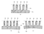
- FIG. 4 is a diagram showing the rotational phases of the orbiting scroll 12 of the compressor 1 according to Embodiment 1.
- FIG. FIG. 4(a) shows the positions of spiral teeth at a rotational phase of 0 (2 ⁇ ) [rad]
- FIG. 4(b) shows the positions of spiral teeth at a rotational phase of ⁇ /2 [rad].
- FIG. 4(c) shows the positions of the spiral teeth at the rotational phase of ⁇ [rad]
- FIG. 4(d) shows the positions of the spiral teeth at the rotational phase of 3 ⁇ /2 [rad].
- the compression mechanism section 10 takes in low-temperature gas from the outer peripheral portion of the container 2, gradually compresses it into high-temperature and high-pressure gas, and discharges it from the central portion. For this reason, a temperature difference and a pressure difference occur between the outer peripheral portion at the end of the winding of the fixed spiral tooth 11b and the oscillating spiral tooth 12b and the central portion at the start of winding. As a result, the deformation amounts of the fixed spiral tooth 11b and the oscillating spiral tooth 12b change between the outer peripheral portion and the central portion. Therefore, there is a difference in height between the fixed spiral tooth 11b and the oscillating spiral tooth 12b.
- FIG. 5 is a diagram showing the state of the oscillating spiral tooth 12b according to Embodiment 1.
- FIG. 5(a) is a diagram showing a state in which the oscillating spiral tooth 12b is not deformed
- FIG. 5(b) is a diagram showing a state in which the oscillating spiral tooth 12b is deformed by thermal expansion
- 5(c) is a diagram showing a state in which the rocking base plate 12a supporting the rocking spiral tooth 12b is curved and deformed. As shown in FIG.
- the tip of one spiral tooth and the other spiral tooth A concave gap that widens toward the center is formed between it and the tooth root. At this time, the tip seal 50 floats up to fill the gap, thereby suppressing gas leakage from the compression chamber 60 .
- FIG. 6 is an axial sectional view showing the compressor 1 according to Embodiment 1.
- the fixed spiral tooth 11b and the oscillating spiral tooth 12b have a thickness that increases or decreases, and have a thick portion 81 and a thin portion 91.
- the wall thickness when the rotational phase (extension angle) of the spiral tooth is ⁇ /2 [rad] and 3 ⁇ /2 [rad] than the wall thickness when 0 (2 ⁇ ) [rad] and ⁇ [rad] is thicker. That is, the thick portion 81 is a portion that overlaps the major axis of the fixed spiral tooth 11b and overlaps the major axis of the oscillating spiral tooth 12b.
- the thick portion 81 is a portion whose extension angle is in the range of N ⁇ /4 [rad].
- N is a natural number including 0.
- the thin portion 91 is a portion that overlaps the minor axis of the fixed spiral tooth 11b and the minor axis of the oscillating spiral tooth 12b.
- the thin portion 91 is a portion whose extension angle is in the range of N ⁇ + ⁇ /2 ⁇ /4 [rad].
- the thick portion 81 has a thick outer wall 82 and a thick inner wall 83 .
- the thick outer wall 82 is provided at the outer end portion in the width direction of the upper end surface of the thick portion 81 and extends in a direction away from the upper end surface.
- the thick inner wall 83 is provided at the inner end portion in the width direction of the upper end surface of the thick portion 81 and extends away from the upper end surface.
- a thick groove 84 into which the tip seal 50 is inserted is formed between the thick outer wall 82 and the thick inner wall 83 . That is, the thick portion 81 has outer walls on both sides of the tip seal 50 .
- the thin portion 91 has a thin outer wall 92 .
- the thin outer wall 92 is provided at the outer end portion in the width direction of the upper end surface and extends in a direction away from the upper end surface.
- a thin groove 94 into which the tip seal 50 is inserted is formed between the thin outer wall 92 and the inner end in the width direction. That is, the outer wall is provided only on the outside of the tip seal 50 in the thin portion 91 .
- FIG. 7 is a schematic diagram showing the thick portion 81 and thin portion 91 according to the first embodiment.
- FIG. 7 is a schematic diagram representing the oscillating spiral tooth 12b in a straight line.
- the thick outer wall 82 and the thin outer wall 92 have the same height, but the thick inner wall 83 draws a smooth curved surface toward the thin portion 91 and becomes lower. becomes 0.
- the height of the thick inner wall 83 changes in a constant cycle with respect to the extension angles of the fixed spiral tooth 11b and the oscillating spiral tooth 12b.
- the thick outer wall 82 and the thick inner wall 83 have the same height.
- the thicker one may be thicker than the thin outer wall 92 .
- the circumferential end of the tip seal 50 is installed in the thin portion 91 .
- the rigidity of the end portion of the groove that holds the tip seal 50 can be ensured. Therefore, it is possible to suppress the deterioration of the reliability of the compressor 1 .
- the fixed spiral tooth 11b and the oscillating spiral tooth 12b are flattened in one direction. , and the thick portion 81 .
- a sufficient contact area can be secured in the thick portion 81 .
- a chip seal 50 is inserted into a thick groove 84 formed between a thick outer wall 82 and a thick inner wall 83 of the thick portion 81 . That is, since the thick outer wall 82 and the thick inner wall 83 are provided on both sides of the tip seal 50, the tip seal 50 can be highly retained. In this way, it is possible to improve the retention of the tip seal 50 while ensuring the contact area.
- the thin portion 91 may have a thin inner wall.
- the thin inner wall is provided at the inner end portion in the width direction of the upper end surface of the thin portion 91, extends away from the upper end surface, and is between the outer end portion in the width direction and the thin groove into which the tip seal 50 is inserted. 94.
- the thicker one of the thick outer wall 82 and the thick outer wall 82 may be thicker than the thin inner wall.
- FIG. 8 is a circumferential cross-sectional view showing compressor 1 according to Embodiment 2. As shown in FIG. Embodiment 2 is different from Embodiment 1 in that a tip seal 50 is provided at the central portion of fixed spiral tooth 11b and oscillating spiral tooth 12b.
- the same reference numerals are assigned to the same parts as in the first embodiment, and the description thereof is omitted.
- the tip seal 50 is provided only at the central portion of the fixed spiral tooth 11b and the oscillating spiral tooth 12b, and is not provided at the outer peripheral portion of the fixed spiral tooth 11b and the oscillating spiral tooth 12b. do not have.
- the central portion refers to the portion in which the extension angle is smaller than 3 ⁇ [rad]
- the outer peripheral portion refers to the portion in which the extension angle is greater than 3 ⁇ [rad].
- FIG. 9 is a diagram showing the state of the oscillating spiral tooth 12b according to the second embodiment. Next, shape changes due to temperature changes and load changes acting on the oscillating spiral tooth 12b will be described.
- FIG. 9(a) is a diagram showing a state in which the oscillating spiral tooth 12b is not deformed
- FIG. 9(b) is a diagram showing a state in which the oscillating spiral tooth 12b is deformed by thermal expansion
- 9(c) is a diagram showing a state in which the rocking base plate 12a supporting the rocking spiral tooth 12b is curved and deformed. As shown in FIG.
- the tip seal 50 is provided at the central portion of the fixed spiral tooth 11b and the oscillating spiral tooth 12b. Therefore, the entire surfaces of the tooth tips of the outer peripheral portions of the fixed spiral tooth 11b and the oscillating spiral tooth 12b can be brought into contact with each other. Therefore, the contact surface pressure acting on the tips of the outer peripheral portions of the fixed spiral tooth 11b and the oscillating spiral tooth 12b can be reduced, so that the reliability of the compressor 1 can be further enhanced.
- the circumferential end portion of the tip seal 50 is installed in the thin portion 91 . Thereby, the rigidity of the end portion of the groove that holds the tip seal 50 can be ensured. Therefore, it is possible to suppress the deterioration of the reliability of the compressor 1 .
- FIG. 10 is a circumferential cross-sectional view showing compressor 1 according to Embodiment 3. As shown in FIG. Embodiment 3 differs from Embodiments 1 and 2 in that the tip seal 50 is not provided in the thin portion 91 .
- the same reference numerals are given to the parts that are common to the first and second embodiments, and the description thereof is omitted.
- the tip seal 50 is provided only on the thick portion 81 and not on the thin portion 91 .
- the thick portion 81 has an extension angle of N ⁇ /4 [rad]
- the thin portion 91 has an extension angle of N ⁇ + ⁇ /2 ⁇ /4 [rad]. rad].
- the tip seal 50 is not provided on the thin portion 91 . Therefore, the amount of tip seal 50 used can be reduced. Therefore, the reliability of the compressor 1 can be improved with less material.
- Compressor 2 Container 2a Oil reservoir 10
- Compression mechanism 11 Fixed scroll 11a Fixed base plate 11b Fixed spiral tooth 12 Oscillating scroll 12a Oscillating bedplate 12b Oscillating spiral tooth 13 Discharge Outlet, 14 frame, 15 rocking bearing, 16 sub-frame, 17 main bearing, 18 sub-bearing, 19 oil pump, 20 electric mechanism, 21 rotor, 22 stator, 30 main shaft, 30a main shaft, 31 eccentric shaft , 32 oil passage, 40 Oldham ring, 41 Oldham groove, 50 chip seal, 51 suction pipe, 52 discharge pipe, 60 compression chamber, 61 baffle, 61a through hole, 62 discharge valve, 63 discharge muffler, 72 first space, 73 Second space 74 Third space 81 Thick part 82 Thick outer wall 83 Thick inner wall 84 Thick groove 91 Thin part 92 Thin outer wall 94 Thin groove 100 Refrigeration cycle device 102 Outdoor unit 103 Indoor unit, 104 Refrigerant circuit, 105 Refrigerant pipe, 107
Abstract
This compressor comprises: a container constituting the outline of the compressor; an electrically operated mechanism provided inside the container; a main shaft that is attached to the electrically operated mechanism and transmits rotational force of the electrically operated mechanism; a fixed scroll having a fixed base plate fixed to inside the container, and fixed spiral teeth provided to the fixed base plate and flattened in one direction; an orbiting scroll having an orbiting base plate connected to an upper end of the main shaft, and orbiting spiral teeth that orbit by means of the rotational force of the electrically operated mechanism and form a compression chamber together with the fixed spiral teeth, the orbiting spiral teeth being flattened in one direction; and a tip seal which is provided on the upper portion of the fixed spiral teeth and the upper portion of the orbiting spiral teeth, and which seals the space between the fixed spiral teeth and the orbiting base plate, and the space between the orbiting spiral teeth and the fixed base plate, wherein a thick-walled portion that overlaps with a major axis on the fixed spiral teeth and overlaps with a major axis on the orbiting spiral teeth has a thick outer wall provided to an outer end in the width direction on the upper end surface of the thick-walled portion, the thick outer wall and extending in a direction away from the upper end surface, and a thick inner wall provided to an inner end in the width direction on the upper end surface of the thick-walled portion, extending in a direction away from the upper end surface, and forming a thick groove into which the tip seal is inserted between the thick outer wall and the thick inner wall.
Description
本開示は、冷媒を圧縮する圧縮機に関する。
The present disclosure relates to a compressor that compresses refrigerant.
従来、空気調和機又は冷凍機等に用いられ、冷媒を圧縮する圧縮機として、スクロール圧縮機が知られている。スクロール圧縮機は、容器と、容器に収容され、固定スクロールと揺動スクロールとが組み合わされて形成された圧縮室において冷媒を圧縮する圧縮機構部とを有している。固定スクロールは、固定台板上に固定渦巻歯が設けられたものであり、揺動スクロールは、揺動台板上に揺動渦巻歯が設けられたものである。圧縮室は、固定渦巻歯と揺動渦巻歯とが噛み合わされて、形成されている。スクロール圧縮機において、揺動スクロールが揺動運動することによって、圧縮室の容積が縮小しながら、圧縮室の位置が変化することによって、冷媒の吸入及び圧縮が行われる。このようなスクロール圧縮機において、容器の径を変えずに、できる限り圧縮室の吸入容積を増加させて、小型化及び低コスト化しつつ、圧縮能力を高める技術が提案されている。固定渦巻歯及び揺動渦巻歯の渦巻形状を工夫することによって、容器の径を変えずに圧縮室の吸入容積を増加させることができる。
Conventionally, a scroll compressor is known as a compressor used in air conditioners, refrigerators, etc. to compress refrigerant. A scroll compressor has a container, and a compression mechanism portion that is housed in the container and compresses a refrigerant in a compression chamber that is formed by combining a fixed scroll and an orbiting scroll. The fixed scroll is provided with fixed spiral teeth on a fixed base plate, and the oscillating scroll is provided with oscillating spiral teeth on an oscillating base plate. The compression chamber is formed by meshing fixed spiral teeth and oscillating spiral teeth. In the scroll compressor, the oscillating movement of the oscillating scroll reduces the volume of the compression chamber and changes the position of the compression chamber, thereby sucking and compressing the refrigerant. In such a scroll compressor, a technique has been proposed in which the suction volume of the compression chamber is increased as much as possible without changing the diameter of the container, thereby increasing the compression capacity while reducing the size and cost. By devising the spiral shapes of the fixed spiral tooth and the oscillating spiral tooth, the suction volume of the compression chamber can be increased without changing the diameter of the container.
スクロール圧縮機は、概して、一方の渦巻歯の歯先と、他方の渦巻歯の歯底とが接触するものである。しかし、圧縮工程において、渦巻歯の巻き始めと巻き終わりとでは、温度差による渦巻歯の熱膨張量に差が生じる。また、渦巻歯の背面に作用する荷重の変化によって、渦巻歯が変形する。これらにより、渦巻歯の歯先に、微小な隙間が形成されて、圧縮室において冷媒等の被圧縮ガスが漏れるおそれがある。この問題を解消することを目的として、特許文献1には、予め渦巻歯の高さが、中央部ほど低くなるように加工されたスクロール圧縮機が開示されている。特許文献1は、これにより、熱膨張後の渦巻歯の高さを揃えようとするものである。
A scroll compressor generally contacts the tip of one spiral tooth and the bottom of the other spiral tooth. However, in the compression process, a difference in the amount of thermal expansion of the spiral tooth occurs due to the temperature difference between the winding start and the winding end of the spiral tooth. In addition, the spiral tooth deforms due to a change in the load acting on the back surface of the spiral tooth. As a result, minute gaps are formed at the tips of the spiral teeth, and compressed gas such as refrigerant may leak in the compression chamber. For the purpose of solving this problem, Patent Literature 1 discloses a scroll compressor in which spiral teeth are processed in advance so that the height of the spiral teeth becomes lower toward the center. Patent document 1 attempts to align the heights of the spiral teeth after thermal expansion.
しかし、特許文献1に係るスクロール圧縮機は、渦巻歯の巻き終わりと巻き始めとで温度差が想定値より低い場合、熱膨張量が少なく、変形もし難くなる。この場合、渦巻歯の歯先と歯底との間に隙間が生じたままとなるため、圧縮室から冷媒が漏れて、圧縮機の性能が低下するおそれがある。また、渦巻歯の巻き終わりと巻き始めとで温度差が想定値より高い場合、熱膨張量が多く、変形もし易くなる。この場合、中央部の渦巻歯が高くなり過ぎて、外周部の渦巻歯の歯先と歯底との間に隙間が発生する。これにより、圧縮室から冷媒が漏れて、圧縮機の性能が低下するおそれがある。
However, in the scroll compressor according to Patent Document 1, when the temperature difference between the winding end and the winding start of the spiral teeth is lower than the assumed value, the amount of thermal expansion is small and deformation is difficult. In this case, since a gap remains between the tip and bottom of the spiral tooth, the refrigerant may leak from the compression chamber, degrading the performance of the compressor. In addition, if the temperature difference between the winding end and the winding start of the spiral tooth is higher than an assumed value, the amount of thermal expansion is large and deformation is likely to occur. In this case, the height of the central spiral tooth is too high, and a gap is generated between the tooth tip and the tooth bottom of the outer peripheral spiral tooth. As a result, the refrigerant may leak from the compression chamber, degrading the performance of the compressor.
特許文献1のような問題を解消することを目的として、概して、渦巻歯の歯先から冷媒が漏れることを抑制するチップシールが設置される場合がある。しかし、チップシールを設置するために、渦巻歯に溝が形成される必要があるため、歯先の接触面積が低下して、接触面圧が増加することによって、圧縮機の信頼性が低下するおそれがある。一方、渦巻歯の歯厚を拡大して、接触面積を確保しようとすると、水平方向の有効スペースに対する渦巻歯の占有率が増加する。このため、有効な圧縮室容積である吸入容積が縮小して、圧縮機の能力が低下するおそれがある。
For the purpose of solving the problem described in Patent Document 1, there are cases where a tip seal is generally installed to suppress leakage of refrigerant from the tips of the spiral teeth. However, since grooves need to be formed in the spiral teeth to install the tip seal, the contact area of the tip of the tooth decreases and the contact surface pressure increases, reducing the reliability of the compressor. There is a risk. On the other hand, if an attempt is made to increase the tooth thickness of the spiral teeth to secure the contact area, the ratio of the spiral teeth occupying the effective space in the horizontal direction increases. For this reason, the suction volume, which is the effective compression chamber volume, is reduced, and there is a risk that the performance of the compressor will be reduced.
この問題を解消することを目的として、特許文献2には、チップシールを保持する溝を形成する側壁が、渦巻歯の外側にのみ設けられたスクロール圧縮機が開示されている。特許文献2は、これにより、歯厚を縮小して、接触面積を確保しようとするものである。
In order to solve this problem, Patent Document 2 discloses a scroll compressor in which side walls forming grooves for holding tip seals are provided only on the outside of spiral teeth. Patent document 2 attempts to secure a contact area by reducing the tooth thickness.
しかしながら、特許文献2に開示されたスクロール圧縮機は、歯先が摺動したり、圧縮室内の圧力が変動したりすることによって、チップシールが変形又は脱落するおそれがある。即ち、特許文献2は、チップシールの保持性に課題がある。
However, in the scroll compressor disclosed in Patent Document 2, there is a risk that the tip seal will deform or come off due to sliding of the tooth tips or fluctuations in the pressure inside the compression chamber. That is, Patent Document 2 has a problem with the retention of the tip seal.
本開示は、上記のような課題を解決するためになされたものであり、接触面積を確保しつつ、チップシールの保持性を向上させる圧縮機を提供することを目的とする。
The present disclosure has been made to solve the above problems, and aims to provide a compressor that improves the retention of the tip seal while ensuring the contact area.
本開示に係る圧縮機は、外郭を構成する容器と、容器の内部に設けられる電動機構部と、電動機構部に取り付けられ、電動機構部の回転力を伝達する主軸と、容器の内部に固定される固定台板と、固定台板に設けられ、一方向に扁平された固定渦巻歯とを有する固定スクロールと、主軸の上端部に接続された揺動台板と、電動機構部の回転力によって揺動して固定渦巻歯と共に圧縮室を形成し、一方向に扁平された揺動渦巻歯とを有する揺動スクロールと、固定渦巻歯の上部及び揺動渦巻歯の上部に設けられ、固定渦巻歯と揺動台板との間及び揺動渦巻歯と固定台板との間をシーリングするチップシールと、を備え、固定渦巻歯において長軸と重なり、揺動渦巻歯において長軸と重なる厚肉部は、上端面において、幅方向の外側端部に設けられ、上端面から離れる方向に延びる厚肉外壁と、上端面において、幅方向の内側端部に設けられ、上端面から離れる方向に延び、厚肉外壁との間に、チップシールが挿入される厚肉溝を形成する厚肉内壁と、を有する。
A compressor according to the present disclosure includes a container forming an outer shell, an electric mechanism provided inside the container, a main shaft attached to the electric mechanism and transmitting a rotational force of the electric mechanism, and fixed inside the container. a fixed scroll provided on the fixed base plate and having fixed spiral teeth flattened in one direction; a rocking base plate connected to the upper end of the main shaft; and an oscillating scroll having an oscillating spiral tooth flattened in one direction to form a compression chamber together with the fixed spiral tooth, and a fixed chip seals for sealing between the spiral tooth and the oscillating bedplate and between the oscillating spiral tooth and the fixed bedplate, overlapping the major axis at the stationary spiral tooth and overlapping the major axis at the oscillating spiral tooth. The thick portion is provided at the outer end in the width direction of the upper end face and extends away from the upper end face, and the thick outer wall is provided at the inner end in the width direction of the upper end face and extends away from the upper end face. and a thick inner wall forming a thick groove between the thick outer wall and into which the tip seal is inserted.
本開示によれば、固定渦巻歯及び揺動渦巻歯が一方向に扁平されており、固定渦巻歯において長軸と重なり、揺動渦巻歯において長軸と重なる部分が、厚肉部となっている。ここで、厚肉部においては、十分な接触面積を確保することができる。そして、厚肉部が有する厚肉外壁と厚肉内壁との間に形成された厚肉溝にチップシールが挿入されている。即ち、チップシールの両側には、厚肉外壁及び厚肉内壁が設けられているため、チップシールの保持性が高い。このように、接触面積を確保しつつ、チップシールの保持性を向上させることができる。
According to the present disclosure, the fixed spiral tooth and the oscillating spiral tooth are flattened in one direction, and the portion of the fixed spiral tooth that overlaps with the major axis and the portion of the oscillating spiral tooth that overlaps with the major axis becomes the thick portion. there is Here, a sufficient contact area can be secured in the thick portion. A tip seal is inserted into a thick groove formed between a thick outer wall and a thick inner wall of the thick portion. That is, since the thick outer wall and the thick inner wall are provided on both sides of the tip seal, the tip seal is highly retainable. In this way, it is possible to improve the retention of the tip seal while ensuring the contact area.
以下、本開示の圧縮機の実施の形態について、図面を参照しながら説明する。なお、本開示は、以下に説明する実施の形態によって限定されるものではない。また、図1を含め、以下の図面では各構成部材の大きさの関係が実際のものとは異なる場合がある。また、以下の説明において、本開示の理解を容易にするために方向を表す用語を適宜用いるが、これは本開示を説明するためのものであって、これらの用語は本開示を限定するものではない。方向を表す用語としては、例えば、「上」、「下」、「右」、「左」、「前」又は「後」等が挙げられる。
Hereinafter, embodiments of the compressor of the present disclosure will be described with reference to the drawings. It should be noted that the present disclosure is not limited by the embodiments described below. In addition, in the following drawings, including FIG. 1, the size relationship of each constituent member may differ from the actual one. In addition, in the following description, directional terms are used as appropriate to facilitate understanding of the present disclosure, but this is for the purpose of describing the present disclosure, and these terms are intended to limit the present disclosure. is not. Directional terms include, for example, "up", "down", "right", "left", "front" or "back".
実施の形態1.
図1は、実施の形態1に係る冷凍サイクル装置100を示す回路図である。冷凍サイクル装置100は、例えば、室内空間の空気を調整する空気調和機であり、図1に示すように、室外機102と、室内機103とを備えている。室外機102には、例えば圧縮機1、流路切替装置107、室外熱交換器108、室外送風機109及び膨張部110が設けられている。室内機103には、例えば室内熱交換器111及び室内送風機112が設けられている。なお、冷凍サイクル装置100は、空気調和機に限らず、冷凍機であってもよい。Embodiment 1.
FIG. 1 is a circuit diagram showing arefrigeration cycle apparatus 100 according to Embodiment 1. FIG. The refrigeration cycle device 100 is, for example, an air conditioner that adjusts air in an indoor space, and includes an outdoor unit 102 and an indoor unit 103 as shown in FIG. The outdoor unit 102 is provided with, for example, a compressor 1 , a channel switching device 107 , an outdoor heat exchanger 108 , an outdoor fan 109 and an expansion section 110 . The indoor unit 103 is provided with, for example, an indoor heat exchanger 111 and an indoor fan 112 . Note that the refrigeration cycle device 100 is not limited to an air conditioner, and may be a refrigerator.
図1は、実施の形態1に係る冷凍サイクル装置100を示す回路図である。冷凍サイクル装置100は、例えば、室内空間の空気を調整する空気調和機であり、図1に示すように、室外機102と、室内機103とを備えている。室外機102には、例えば圧縮機1、流路切替装置107、室外熱交換器108、室外送風機109及び膨張部110が設けられている。室内機103には、例えば室内熱交換器111及び室内送風機112が設けられている。なお、冷凍サイクル装置100は、空気調和機に限らず、冷凍機であってもよい。
FIG. 1 is a circuit diagram showing a
圧縮機1、流路切替装置107、室外熱交換器108、膨張部110及び室内熱交換器111が冷媒配管105により接続されて冷媒回路104が構成されている。圧縮機1は、低温且つ低圧の状態の冷媒を吸入し、吸入した冷媒を圧縮して高温且つ高圧の状態の冷媒にして吐出するものである。圧縮機1は、例えば容量制御可能なインバータ圧縮機である。流路切替装置107は、冷媒回路104において冷媒が流れる方向を切り替えるものであり、例えば四方弁である。室外熱交換器108は、例えば室外空気と冷媒との間で熱交換するものである。室外熱交換器108は、冷房運転時には凝縮器として作用し、暖房運転時には蒸発器として作用する。膨張部110は、冷媒を減圧して膨張する減圧弁又は膨張弁である。膨張部110は、例えば開度が調整される電子式膨張弁である。
A refrigerant circuit 104 is configured by connecting the compressor 1 , the flow switching device 107 , the outdoor heat exchanger 108 , the expansion section 110 and the indoor heat exchanger 111 by refrigerant pipes 105 . The compressor 1 sucks a low-temperature, low-pressure refrigerant, compresses the sucked refrigerant, converts it into a high-temperature, high-pressure refrigerant, and discharges it. The compressor 1 is, for example, a capacity-controllable inverter compressor. The channel switching device 107 switches the direction in which the refrigerant flows in the refrigerant circuit 104, and is, for example, a four-way valve. The outdoor heat exchanger 108 exchanges heat, for example, between outdoor air and refrigerant. The outdoor heat exchanger 108 acts as a condenser during cooling operation and acts as an evaporator during heating operation. The expansion unit 110 is a pressure reducing valve or an expansion valve that reduces the pressure of the refrigerant to expand it. The expansion part 110 is, for example, an electronic expansion valve whose opening is adjusted.
室内熱交換器111は、例えば室内空気と冷媒との間で熱交換するものである。室内熱交換器111は、冷房運転時には蒸発器として作用し、暖房運転時には凝縮器として作用する。室内送風機112は、室内熱交換器111に室内空気を送る機器である。
The indoor heat exchanger 111 exchanges heat, for example, between indoor air and refrigerant. The indoor heat exchanger 111 acts as an evaporator during cooling operation, and acts as a condenser during heating operation. The indoor fan 112 is a device that sends indoor air to the indoor heat exchanger 111 .
(運転モード、冷房運転)
次に、冷凍サイクル装置100の運転モードについて説明する。先ず、冷房運転について説明する。冷房運転において、圧縮機1に吸入された冷媒は、圧縮機1によって圧縮されて高温且つ高圧のガス状態で吐出する。圧縮機1から吐出された高温且つ高圧のガス状態の冷媒は、流路切替装置107を通過して、凝縮器として作用する室外熱交換器108に流入し、室外熱交換器108において、室外送風機109によって送られる室外空気と熱交換されて凝縮して液化する。凝縮された液状態の冷媒は、膨張部110に流入し、膨張部110において膨張及び減圧されて低温且つ低圧の気液二相状態の冷媒となる。そして、気液二相状態の冷媒は、蒸発器として作用する室内熱交換器111に流入し、室内熱交換器111において、室内送風機112によって送られる室内空気と熱交換されて蒸発してガス化する。このとき、室内空気が冷やされ、室内において冷房が実施される。蒸発した低温且つ低圧のガス状態の冷媒は、流路切替装置107を通過して、圧縮機1に吸入される。 (Operating mode, cooling operation)
Next, operation modes of therefrigeration cycle apparatus 100 will be described. First, the cooling operation will be explained. In the cooling operation, the refrigerant sucked into the compressor 1 is compressed by the compressor 1 and discharged in a high-temperature and high-pressure gas state. The high-temperature and high-pressure gaseous refrigerant discharged from the compressor 1 passes through the flow switching device 107 and flows into the outdoor heat exchanger 108 acting as a condenser. It is heat-exchanged with outdoor air sent by 109 to condense and liquefy. The condensed liquid refrigerant flows into the expansion section 110 and is expanded and decompressed in the expansion section 110 to become a low-temperature, low-pressure gas-liquid two-phase refrigerant. Then, the gas-liquid two-phase refrigerant flows into the indoor heat exchanger 111 acting as an evaporator, and in the indoor heat exchanger 111, heat is exchanged with the indoor air sent by the indoor blower 112 to evaporate and gasify. do. At this time, the indoor air is cooled, and cooling is performed in the room. The vaporized low-temperature, low-pressure gaseous refrigerant passes through the flow path switching device 107 and is sucked into the compressor 1 .
次に、冷凍サイクル装置100の運転モードについて説明する。先ず、冷房運転について説明する。冷房運転において、圧縮機1に吸入された冷媒は、圧縮機1によって圧縮されて高温且つ高圧のガス状態で吐出する。圧縮機1から吐出された高温且つ高圧のガス状態の冷媒は、流路切替装置107を通過して、凝縮器として作用する室外熱交換器108に流入し、室外熱交換器108において、室外送風機109によって送られる室外空気と熱交換されて凝縮して液化する。凝縮された液状態の冷媒は、膨張部110に流入し、膨張部110において膨張及び減圧されて低温且つ低圧の気液二相状態の冷媒となる。そして、気液二相状態の冷媒は、蒸発器として作用する室内熱交換器111に流入し、室内熱交換器111において、室内送風機112によって送られる室内空気と熱交換されて蒸発してガス化する。このとき、室内空気が冷やされ、室内において冷房が実施される。蒸発した低温且つ低圧のガス状態の冷媒は、流路切替装置107を通過して、圧縮機1に吸入される。 (Operating mode, cooling operation)
Next, operation modes of the
(運転モード、暖房運転)
次に、暖房運転について説明する。暖房運転において、圧縮機1に吸入された冷媒は、圧縮機1によって圧縮されて高温且つ高圧のガス状態で吐出する。圧縮機1から吐出された高温且つ高圧のガス状態の冷媒は、流路切替装置107を通過して、凝縮器として作用する室内熱交換器111に流入し、室内熱交換器111において、室内送風機112によって送られる室内空気と熱交換されて凝縮して液化する。このとき、室内空気が暖められ、室内において暖房が実施される。凝縮された液状態の冷媒は、膨張部110に流入し、膨張部110において膨張及び減圧されて低温且つ低圧の気液二相状態の冷媒となる。そして、気液二相状態の冷媒は、蒸発器として作用する室外熱交換器108に流入し、室外熱交換器108において、室外送風機109によって送られる室外空気と熱交換されて蒸発してガス化する。蒸発した低温且つ低圧のガス状態の冷媒は、流路切替装置107を通過して、圧縮機1に吸入される。 (Operating mode, heating operation)
Next, the heating operation will be explained. In the heating operation, the refrigerant sucked into thecompressor 1 is compressed by the compressor 1 and discharged in a high-temperature and high-pressure gas state. The high-temperature and high-pressure gaseous refrigerant discharged from the compressor 1 passes through the flow path switching device 107 and flows into the indoor heat exchanger 111 acting as a condenser. It is heat-exchanged with the room air sent by 112 to condense and liquefy. At this time, the indoor air is warmed, and heating is performed in the room. The condensed liquid refrigerant flows into the expansion section 110 and is expanded and decompressed in the expansion section 110 to become a low-temperature, low-pressure gas-liquid two-phase refrigerant. Then, the gas-liquid two-phase refrigerant flows into the outdoor heat exchanger 108 acting as an evaporator, where it is heat-exchanged with the outdoor air sent by the outdoor blower 109 to evaporate and gasify. do. The vaporized low-temperature, low-pressure gaseous refrigerant passes through the flow path switching device 107 and is sucked into the compressor 1 .
次に、暖房運転について説明する。暖房運転において、圧縮機1に吸入された冷媒は、圧縮機1によって圧縮されて高温且つ高圧のガス状態で吐出する。圧縮機1から吐出された高温且つ高圧のガス状態の冷媒は、流路切替装置107を通過して、凝縮器として作用する室内熱交換器111に流入し、室内熱交換器111において、室内送風機112によって送られる室内空気と熱交換されて凝縮して液化する。このとき、室内空気が暖められ、室内において暖房が実施される。凝縮された液状態の冷媒は、膨張部110に流入し、膨張部110において膨張及び減圧されて低温且つ低圧の気液二相状態の冷媒となる。そして、気液二相状態の冷媒は、蒸発器として作用する室外熱交換器108に流入し、室外熱交換器108において、室外送風機109によって送られる室外空気と熱交換されて蒸発してガス化する。蒸発した低温且つ低圧のガス状態の冷媒は、流路切替装置107を通過して、圧縮機1に吸入される。 (Operating mode, heating operation)
Next, the heating operation will be explained. In the heating operation, the refrigerant sucked into the
なお、冷凍サイクル装置100は、流路切替装置107を有していなくてもよい。この場合、冷凍サイクル装置100は、冷房専用機又は暖房専用機となる。
Note that the refrigeration cycle device 100 does not have to have the channel switching device 107 . In this case, the refrigeration cycle device 100 becomes a dedicated cooling machine or a dedicated heating machine.
図2は、実施の形態1に係る圧縮機1を示す軸方向断面図である。次に、圧縮機1について詳細に説明する。圧縮機1は、例えば冷媒回路104を循環する冷媒を吸入して圧縮し、高温且つ高圧の状態にして吐出するものであり、例えば密閉型のスクロール圧縮機である。圧縮機1は、図2に示すように、容器2と、フレーム14と、サブフレーム16と、主軸30と、主軸受17と、副軸受18と、吸入管51と、吐出管52と、圧縮機構部10とを有している。また、圧縮機1は、オルダムリング40と、油ポンプ19と、電動機構部20とを備えている。
FIG. 2 is an axial sectional view showing the compressor 1 according to Embodiment 1. FIG. Next, the compressor 1 will be explained in detail. The compressor 1 sucks and compresses the refrigerant circulating in the refrigerant circuit 104, for example, and discharges the refrigerant in a high-temperature and high-pressure state, and is, for example, a hermetic scroll compressor. As shown in FIG. 2, the compressor 1 includes a container 2, a frame 14, a sub-frame 16, a main shaft 30, a main bearing 17, a sub-bearing 18, a suction pipe 51, a discharge pipe 52, a compression and a mechanism section 10 . The compressor 1 also includes an Oldham ring 40 , an oil pump 19 , and an electric mechanism section 20 .
容器2は、圧縮機1の外殻を構成する密閉されたものであり、円筒状をなしている。容器2の内部には、圧縮機構部10、電動機構部20及びそのほかの部品が収納されている。容器2内において、上方に圧縮機構部10が配置され、下方に電動機構部20が配置されている。容器2の底部43には、冷凍機油を貯留する油溜まり部2aが形成されている。
The container 2 is a closed container that constitutes the outer shell of the compressor 1 and has a cylindrical shape. Inside the container 2, the compression mechanism section 10, the electric mechanism section 20, and other parts are accommodated. Inside the container 2, the compression mechanism section 10 is arranged above and the electric mechanism section 20 is arranged below. A bottom portion 43 of the container 2 is formed with an oil reservoir portion 2a that stores refrigerating machine oil.
フレーム14は、容器2に固定され、圧縮機構部10を収容するものであり、例えば主軸受17を介して主軸30を回転自在に支持している。フレーム14は、電動機構部20の上方に配置されて電動機構部20と圧縮機構部10との間に位置している。フレーム14の内部には、吐出管52が接続されている。圧縮された冷媒は、フレーム14内を通って、吐出管52から吐出される。
The frame 14 is fixed to the container 2 and accommodates the compression mechanism section 10, and rotatably supports the main shaft 30 via main bearings 17, for example. The frame 14 is arranged above the electric mechanism portion 20 and positioned between the electric mechanism portion 20 and the compression mechanism portion 10 . A discharge pipe 52 is connected to the inside of the frame 14 . The compressed refrigerant passes through the frame 14 and is discharged from the discharge pipe 52 .
サブフレーム16は、容器2の内部における電動機構部20の下方に配置されている。サブフレーム16は、副軸受18を介して主軸30を回転自在に支持するものである。フレーム14とサブフレーム16とは、電動機構部20を挟んで対向するように、容器2の内部に固定されている。フレーム14及びサブフレーム16は、焼嵌又は溶接等によって容器2の内周面に固着されている。主軸30は、容器2の中央においてフレーム14に支持され、上下方向に延びる棒状のクランク軸であり、電動機構部20と圧縮機構部10とを接続している。
The subframe 16 is arranged below the electric mechanism section 20 inside the container 2 . The subframe 16 rotatably supports the main shaft 30 via the subbearing 18 . The frame 14 and the sub-frame 16 are fixed inside the container 2 so as to face each other with the electric mechanism section 20 interposed therebetween. The frame 14 and subframe 16 are fixed to the inner peripheral surface of the container 2 by shrink fitting, welding, or the like. The main shaft 30 is supported by the frame 14 at the center of the container 2 and is a rod-shaped crankshaft extending vertically, and connects the electric mechanism section 20 and the compression mechanism section 10 .
主軸30は、電動機構部20と圧縮機構部10とを接続して電動機構部20の回転力を圧縮機構部10に伝達する。主軸30の上端部には、揺動スクロール12の揺動台板12aが設けられている。主軸30は、偏心軸部31と、主軸部30aとを有している。偏心軸部31は、主軸30の軸心に対して偏心されたものであり、揺動軸受15に回転自在に収容されている。偏心軸部31の外周部は、揺動軸受15の内周部と冷凍機油を介して密着している。主軸部30aは、フレーム14に設けられた主軸受17によって支持されている。主軸部30aには、電動機構部20のロータが焼き嵌め等によって固定されている。主軸30の内部には、油が通る油通路32が形成されている。主軸受17は、フレーム14の中央部に設けられており、主軸30の上部を回転自在に支持する。副軸受18は、サブフレーム16の中央部に圧入されて設けられており、主軸30の下部を回転自在に支持する。
The main shaft 30 connects the electric mechanism portion 20 and the compression mechanism portion 10 to transmit the rotational force of the electric mechanism portion 20 to the compression mechanism portion 10 . A rocking bed plate 12 a of the rocking scroll 12 is provided at the upper end of the main shaft 30 . The main shaft 30 has an eccentric shaft portion 31 and a main shaft portion 30a. The eccentric shaft portion 31 is eccentric with respect to the axis of the main shaft 30 and is rotatably accommodated in the rocking bearing 15 . The outer peripheral portion of the eccentric shaft portion 31 is in close contact with the inner peripheral portion of the swing bearing 15 via the refrigerator oil. The main shaft portion 30 a is supported by a main bearing 17 provided on the frame 14 . A rotor of the electric mechanism portion 20 is fixed to the main shaft portion 30a by shrink fitting or the like. An oil passage 32 through which oil passes is formed inside the main shaft 30 . The main bearing 17 is provided in the central portion of the frame 14 and supports the upper portion of the main shaft 30 so as to be rotatable. The sub-bearing 18 is press-fitted into the central portion of the sub-frame 16 and supports the lower portion of the main shaft 30 so as to be rotatable.
吸入管51は、容器2の側部において、圧縮機構部10の固定スクロール11に形成された第1空間72に接続されている。吸入管44は、冷媒配管105から流れる低圧の冷媒を、第1空間72に吸入する。吐出管52は、容器2の側部において、フレーム14に形成された空間に接続されている。吐出管52は、圧縮機構部10によって圧縮された高圧の冷媒を、圧縮機1の外部の冷媒配管105に吐出する。
The suction pipe 51 is connected to the first space 72 formed in the fixed scroll 11 of the compression mechanism section 10 on the side of the container 2 . The suction pipe 44 sucks the low-pressure refrigerant flowing from the refrigerant pipe 105 into the first space 72 . The discharge pipe 52 is connected to the space formed in the frame 14 on the side of the container 2 . The discharge pipe 52 discharges the high-pressure refrigerant compressed by the compression mechanism section 10 to the refrigerant pipe 105 outside the compressor 1 .
圧縮機構部10は、吸入管51から吸入された冷媒を圧縮し、容器2の内部における圧縮機構部10外に排出する。圧縮機構部10は、固定スクロール11と揺動スクロール12とを有している。固定スクロール11は、揺動スクロール12の上方において容器2に固定されており、固定台板11aと、固定渦巻歯11bとを有している。固定台板11aは、板状の部材であり、圧縮機構部10の上面を構成する。固定台板11aの中央部には、吐出口13が形成されており、固定台板11aの側方には、第1空間72が形成されている。固定渦巻歯11bは、固定台板11aの下面から下方に延びる渦巻状突起である。
The compression mechanism section 10 compresses the refrigerant sucked from the suction pipe 51 and discharges it outside the compression mechanism section 10 inside the container 2 . The compression mechanism section 10 has a fixed scroll 11 and an orbiting scroll 12 . The fixed scroll 11 is fixed to the container 2 above the orbiting scroll 12, and has a fixed base plate 11a and fixed spiral teeth 11b. The fixed base plate 11 a is a plate-like member and constitutes the upper surface of the compression mechanism section 10 . A discharge port 13 is formed in the central portion of the fixed base plate 11a, and a first space 72 is formed on the side of the fixed base plate 11a. The fixed spiral tooth 11b is a spiral protrusion extending downward from the lower surface of the fixed base plate 11a.
揺動スクロール12は、揺動台板12aと、揺動渦巻歯12bとを有している。揺動台板12aは、フレーム14の上方に配置される板状の部材である。揺動渦巻歯12bは、揺動台板12aの上面から上方に延びる渦巻状突起である。固定スクロール11及び揺動スクロール12は、固定渦巻歯11bと揺動渦巻歯12bとが互いに噛み合った状態で、容器2内に設けられている。固定渦巻歯11b及び揺動渦巻歯12bは、インボリュート曲線に倣って形成されており、固定渦巻歯11b及び揺動渦巻歯12bが噛み合った状態で組み合わせられることにより、固定渦巻歯11bと揺動渦巻歯12bとの間に、複数の圧縮室60が形成される。揺動スクロール12が揺動しているとき、揺動渦巻歯12bが軸方向に浮上することによって、固定渦巻歯11bと揺動渦巻歯12bとが噛み合って圧縮室60が形成される。
The orbiting scroll 12 has an orbiting base plate 12a and an orbiting spiral tooth 12b. The rocking plate 12 a is a plate-like member arranged above the frame 14 . The oscillating spiral tooth 12b is a spiral projection extending upward from the upper surface of the oscillating base plate 12a. The fixed scroll 11 and the orbiting scroll 12 are provided inside the container 2 with the fixed spiral teeth 11b and the orbiting spiral teeth 12b meshing with each other. The fixed spiral tooth 11b and the oscillating spiral tooth 12b are formed following an involute curve. A plurality of compression chambers 60 are formed between the teeth 12b. When the orbiting scroll 12 is oscillating, the oscillating spiral teeth 12b float in the axial direction, so that the fixed spiral teeth 11b and the oscillating spiral teeth 12b mesh with each other to form compression chambers 60. As shown in FIG.
揺動スクロール12と偏心軸部31との間には、揺動軸受15が設けられている。揺動軸受15は、主軸30と、偏心軸部31とを覆い、主軸30を回転自在に支持する。偏心軸部31は、主軸30の上端に設けられ、揺動スクロール12を偏心回転させる。オルダムリング40は、揺動スクロール12において揺動渦巻歯12bが形成された面と反対側であるスラスト面に設けられている。オルダムリング40は、揺動スクロール12の偏心旋回運動中における自転運動を阻止し、揺動スクロール12の公転運動を可能とする。なお、オルダムリング40の上面及び下面には、互いに直交するように突設された爪(図示せず)が設けられている。オルダムリング40の爪は、揺動スクロール12及びフレーム14に形成されたオルダム溝41(図3参照)に挿入されている。
A swing bearing 15 is provided between the swing scroll 12 and the eccentric shaft portion 31 . The swing bearing 15 covers the main shaft 30 and the eccentric shaft portion 31 and supports the main shaft 30 rotatably. The eccentric shaft portion 31 is provided at the upper end of the main shaft 30 and eccentrically rotates the orbiting scroll 12 . The Oldham ring 40 is provided on the thrust surface of the orbiting scroll 12 opposite to the surface on which the orbiting spiral teeth 12b are formed. The Oldham ring 40 prevents the orbiting scroll 12 from rotating during the eccentric orbiting motion, and allows the orbiting scroll 12 to revolve. The upper and lower surfaces of the Oldham's ring 40 are provided with claws (not shown) projecting perpendicularly to each other. The claws of the Oldham ring 40 are inserted into Oldham grooves 41 (see FIG. 3) formed in the orbiting scroll 12 and frame 14 .
油ポンプ19は、容器2の底部43に収容され、油溜まり部2aから油を吸い上げる。油ポンプ19は、主軸30の下部に固着されている。油ポンプ19は、油溜まり部2aに貯留する油を主軸30の内部に形成された油通路32に吸い上げ、油通路32を通って副軸受18、主軸受17及び揺動軸受15に供給する。なお、油ポンプ19は、省略されてもよい。この場合、例えば、差圧を用いて油溜まり部2aから油を吸い上げる構成が採用される。
The oil pump 19 is accommodated in the bottom portion 43 of the container 2 and sucks up oil from the oil reservoir portion 2a. The oil pump 19 is fixed to the lower portion of the main shaft 30 . The oil pump 19 sucks up the oil stored in the oil reservoir 2 a into an oil passage 32 formed inside the main shaft 30 and supplies the oil to the auxiliary bearing 18 , the main bearing 17 and the oscillating bearing 15 through the oil passage 32 . Note that the oil pump 19 may be omitted. In this case, for example, a configuration is adopted in which oil is sucked up from the oil reservoir portion 2a using differential pressure.
電動機構部20は、容器2の内部の下部に設けられている。電動機構部20は、圧縮機構部10を構成する揺動スクロール12を駆動する。即ち、電動機構部20は、主軸30を介して揺動スクロール12を回転駆動することによって、圧縮機構部10において冷媒が圧縮される。電動機構部20は、回転子21と、固定子22とを有している。回転子21は、固定子22の内周側に設けられている。回転子21は、固定子22に通電されることによって回転駆動し、主軸30を回転させる。回転子21は、主軸30の外周に固定されており、固定子22と僅かな隙間を隔てて保持されている。
The electric mechanism part 20 is provided in the lower part inside the container 2 . The electric mechanism section 20 drives the orbiting scroll 12 that constitutes the compression mechanism section 10 . That is, the motor-driven mechanism section 20 rotates the orbiting scroll 12 via the main shaft 30 , thereby compressing the refrigerant in the compression mechanism section 10 . The electric mechanism section 20 has a rotor 21 and a stator 22 . The rotor 21 is provided inside the stator 22 . The rotor 21 is rotationally driven by energizing the stator 22 to rotate the main shaft 30 . The rotor 21 is fixed to the outer periphery of the main shaft 30 and held with a small gap from the stator 22 .
(圧縮機1の動作)
次に、圧縮機1の動作について説明する。容器2に設けられた電源端子(図示せず)に通電されると、固定子22のコイルに電流が流れて、磁界が発生する。固定子22における磁界の発生によって、回転子21を貫通する主軸部30aが回転する。主軸部30aが回転することによって、偏心軸部31が偏心回転して、揺動スクロール12がオルダムリング40により自転を規制された状態で、揺動半径で偏心旋回運動する。ここで、揺動半径とは、主軸部30aに対する偏心軸部31の偏心量をいう。 (Operation of compressor 1)
Next, operation of thecompressor 1 will be described. When a power supply terminal (not shown) provided on the container 2 is energized, current flows through the coils of the stator 22 to generate a magnetic field. Due to the magnetic field generated in the stator 22, the main shaft portion 30a passing through the rotor 21 rotates. When the main shaft portion 30a rotates, the eccentric shaft portion 31 rotates eccentrically, and the orbiting scroll 12 eccentrically orbits with the oscillation radius while its rotation is restricted by the Oldham ring 40. FIG. Here, the swing radius refers to the amount of eccentricity of the eccentric shaft portion 31 with respect to the main shaft portion 30a.
次に、圧縮機1の動作について説明する。容器2に設けられた電源端子(図示せず)に通電されると、固定子22のコイルに電流が流れて、磁界が発生する。固定子22における磁界の発生によって、回転子21を貫通する主軸部30aが回転する。主軸部30aが回転することによって、偏心軸部31が偏心回転して、揺動スクロール12がオルダムリング40により自転を規制された状態で、揺動半径で偏心旋回運動する。ここで、揺動半径とは、主軸部30aに対する偏心軸部31の偏心量をいう。 (Operation of compressor 1)
Next, operation of the
室内熱交換器111から流出した低圧の冷媒は、吸入管51から容器2の固定台板11aの第1空間72に吸入される。第1空間72に流入した低圧の冷媒は、フレーム14内に設置された2つの開口部(図示せず)を通って、第2空間73に流入する。第2空間73に流入した低圧の冷媒は、固定渦巻歯11bに対する揺動渦巻歯12bの相対的な揺動動作に伴って、圧縮室60に吸い込まれる。冷媒を取り込んだ圧縮室60は、揺動スクロール12の偏心旋回運動に伴って、外周側から中心側に移動しながら自身の容積が減り、これにより冷媒を圧縮する。
The low-pressure refrigerant flowing out of the indoor heat exchanger 111 is sucked into the first space 72 of the fixed base plate 11 a of the container 2 through the suction pipe 51 . The low-pressure refrigerant that has flowed into the first space 72 flows into the second space 73 through two openings (not shown) provided in the frame 14 . The low-pressure refrigerant that has flowed into the second space 73 is sucked into the compression chamber 60 as the oscillating spiral tooth 12b oscillates relative to the fixed spiral tooth 11b. As the orbiting scroll 12 eccentrically revolves, the compression chamber 60 that has taken in the refrigerant decreases in volume while moving from the outer circumference to the center, thereby compressing the refrigerant.
その際、冷媒は、固定渦巻歯11bに対する揺動渦巻歯12bの相対的な揺動動作に伴う圧縮室60の幾何学的な容積変化によって、低圧から高圧に昇圧される。圧縮された高圧の冷媒は、固定スクロール11の吐出口13及びバッフル61の貫通孔61aを通過して、吐出バルブ62を押し開けて吐出マフラ63の内部に吐出される。吐出マフラ63内に吐出された高圧の冷媒は、第3空間74に流入して、吐出管52から圧縮機1の外部に吐出される。なお、第3空間74と吐出管52とは、フレーム14等を介して連通している。
At that time, the refrigerant is boosted from a low pressure to a high pressure due to the geometric volume change of the compression chamber 60 caused by the relative oscillating motion of the oscillating spiral tooth 12b with respect to the fixed spiral tooth 11b. The compressed high-pressure refrigerant passes through the discharge port 13 of the fixed scroll 11 and the through hole 61 a of the baffle 61 , pushes the discharge valve 62 open, and is discharged into the discharge muffler 63 . The high-pressure refrigerant discharged into the discharge muffler 63 flows into the third space 74 and is discharged from the compressor 1 through the discharge pipe 52 . The third space 74 and the discharge pipe 52 communicate with each other through the frame 14 and the like.
図3は、実施の形態1に係る圧縮機1を示す周方向断面図である。図3に示すように、容器2は、周方向断面において真円状であり、容器2の内部において、フレーム14の外周面が容器2の内周面に接触した状態で、固着されている。このように、フレーム14の外周面も、真円状である。フレーム14の第2空間73には、固定スクロール11及び揺動スクロール12が配置されている。なお、第2空間73には、オルダムリング40が設けられるオルダム溝41が形成されている。ここで、揺動台板12aは、一方向に扁平されている。ここで、扁平とは、長円形状及び楕円形状を含むものであり、円形状よりも平たい形状をいう。なお、オルダム溝41は、揺動台板12aの短軸側に配置されている。このため、揺動する揺動台板12aとオルダム溝41とが干渉しない。
FIG. 3 is a circumferential cross-sectional view showing the compressor 1 according to Embodiment 1. FIG. As shown in FIG. 3 , the container 2 has a circular cross section in the circumferential direction, and inside the container 2 , the outer peripheral surface of the frame 14 is fixed in contact with the inner peripheral surface of the container 2 . Thus, the outer peripheral surface of the frame 14 is also perfectly circular. A fixed scroll 11 and an orbiting scroll 12 are arranged in the second space 73 of the frame 14 . An Oldham groove 41 in which the Oldham ring 40 is provided is formed in the second space 73 . Here, the rocking plate 12a is flattened in one direction. Here, the term "flat" includes an oval shape and an elliptical shape, and refers to a shape that is flatter than a circular shape. The Oldham's groove 41 is arranged on the short axis side of the rocking plate 12a. Therefore, the rocking rocking plate 12a and the Oldham's groove 41 do not interfere with each other.
図3に示すように、固定渦巻歯11b及び揺動渦巻歯12bは、一方向に扁平されている。前述の如く、揺動台板12aも扁平しているため、揺動台板12aに設けられる揺動渦巻歯12bが扁平していることによって、揺動台板12a上のスペースを有効に活用することができる。このように、スペースの効率を高めることによって、容器2の大きさを変更せずに、圧縮室60の容積を拡大することができる。従って、圧縮機1の能力を向上させることができる。また、圧縮機1の能力を維持したまま、容器2の小型化を図ることができる。なお、以下の説明において、固定渦巻歯11b及び揺動渦巻歯12bの両方を区別せずに示す際、渦巻歯と総称する。また、以下の説明において、固定台板11a及び揺動台板12aの両方を区別せずに示す際、台板と総称する。
As shown in FIG. 3, the fixed spiral tooth 11b and the oscillating spiral tooth 12b are flattened in one direction. As described above, since the rocking bed plate 12a is also flat, the space on the rocking bed plate 12a can be effectively utilized by flattening the rocking spiral teeth 12b provided on the rocking bed plate 12a. be able to. Thus, by increasing space efficiency, the volume of the compression chamber 60 can be increased without changing the size of the container 2 . Therefore, the performance of the compressor 1 can be improved. Further, the size of the container 2 can be reduced while maintaining the performance of the compressor 1 . In the following description, when both the fixed spiral tooth 11b and the oscillating spiral tooth 12b are shown without distinction, they are collectively referred to as spiral teeth. In addition, in the following description, when both the fixed base plate 11a and the rocking base plate 12a are shown without distinction, they are collectively referred to as base plates.
ここで、固定渦巻歯11bの上部及び揺動渦巻歯12bの上部には、チップシール50が設けられている。ここで、固定渦巻歯11bの上部及び揺動渦巻歯12bの上部とは、それぞれ固定渦巻歯11bの先端及び揺動渦巻歯12bの先端である。チップシール50は、固定渦巻歯11bと揺動台板12aとの間及び揺動渦巻歯12bと固定台板11aとの間をシーリングするものである。チップシール50は、固定渦巻歯11b及び揺動渦巻歯12bの上端面に形成された溝に挿入されている。即ち、チップシール50も、固定渦巻歯11b及び揺動渦巻歯12bと同様に、一方向に扁平されている。なお、チップシール50の扁平度合は、固定渦巻歯11b及び揺動渦巻歯12bの扁平度合と異なっていてもよい。
Here, tip seals 50 are provided above the fixed spiral teeth 11b and above the oscillating spiral teeth 12b. Here, the upper portion of the fixed spiral tooth 11b and the upper portion of the oscillating spiral tooth 12b are the tip of the fixed spiral tooth 11b and the tip of the oscillating spiral tooth 12b, respectively. The tip seal 50 seals between the fixed spiral tooth 11b and the oscillating base plate 12a and between the oscillating spiral tooth 12b and the fixed base plate 11a. The tip seal 50 is inserted into grooves formed in the upper end faces of the fixed spiral tooth 11b and the oscillating spiral tooth 12b. That is, the tip seal 50 is also flattened in one direction like the fixed spiral tooth 11b and the oscillating spiral tooth 12b. The degree of flatness of the tip seal 50 may be different from the degree of flatness of the fixed spiral tooth 11b and the oscillating spiral tooth 12b.
図4は、実施の形態1に係る圧縮機1の揺動スクロール12の回転位相を示す図である。図4(a)は、回転位相0(2π)[rad]の渦巻歯の位置を示し、図4(b)は、回転位相π/2[rad]の渦巻歯の位置を示す。図4(c)は、回転位相π[rad]の渦巻歯の位置を示し、図4(d)は、回転位相3π/2[rad]の渦巻歯の位置を示す。このように、渦巻歯の渦巻形状が扁平している場合、一定の揺動半径で揺動渦巻歯12bが動作すると、揺動渦巻歯12bの外向面と内向面とが互いに相対する固定渦巻歯11bの内向面と外向面とに接触する。
FIG. 4 is a diagram showing the rotational phases of the orbiting scroll 12 of the compressor 1 according to Embodiment 1. FIG. FIG. 4(a) shows the positions of spiral teeth at a rotational phase of 0 (2π) [rad], and FIG. 4(b) shows the positions of spiral teeth at a rotational phase of π/2 [rad]. FIG. 4(c) shows the positions of the spiral teeth at the rotational phase of π [rad], and FIG. 4(d) shows the positions of the spiral teeth at the rotational phase of 3π/2 [rad]. In this way, when the spiral shape of the spiral tooth is flat, when the oscillating spiral tooth 12b operates with a constant oscillating radius, the outward surface and the inward surface of the oscillating spiral tooth 12b face each other. It contacts the inward and outward surfaces of 11b.
このとき、圧縮機構部10は、容器2の外周部から低温のガスを吸入し、徐々に高温且つ高圧のガスに圧縮して、中央部から放出する。このため、固定渦巻歯11b及び揺動渦巻歯12bの巻き終わりの外周部と、巻き始めの中央部とで、温度差及び圧力差が生じる。これにより、固定渦巻歯11b及び揺動渦巻歯12bの変形量が、外周部と中央部とで変化する。従って、固定渦巻歯11b及び揺動渦巻歯12bの高さに差が生じる。
At this time, the compression mechanism section 10 takes in low-temperature gas from the outer peripheral portion of the container 2, gradually compresses it into high-temperature and high-pressure gas, and discharges it from the central portion. For this reason, a temperature difference and a pressure difference occur between the outer peripheral portion at the end of the winding of the fixed spiral tooth 11b and the oscillating spiral tooth 12b and the central portion at the start of winding. As a result, the deformation amounts of the fixed spiral tooth 11b and the oscillating spiral tooth 12b change between the outer peripheral portion and the central portion. Therefore, there is a difference in height between the fixed spiral tooth 11b and the oscillating spiral tooth 12b.
図5は、実施の形態1に係る揺動渦巻歯12bの状態を示す図である。次に、揺動渦巻歯12bに作用する温度変化及び荷重変化による形状変化について説明する。図5(a)は、揺動渦巻歯12bが変形していない状態を示す図であり、図5(b)は、揺動渦巻歯12bが熱膨張によって変形した状態を示す図であり、図5(c)は、揺動渦巻歯12bを支持する揺動台板12aが湾曲変形した状態を示す図である。図5(a)に示すように、揺動渦巻歯12bが変形していない場合、又は、揺動渦巻歯12bの変形量が少ない場合、一方の渦巻歯の歯先と、他方の渦巻歯の歯底との間に、中心に向かって広がる凹状の隙間が形成される。このとき、チップシール50が浮上することによって、隙間が埋まるため、圧縮室60からのガスの漏れを抑制することができる。
FIG. 5 is a diagram showing the state of the oscillating spiral tooth 12b according to Embodiment 1. FIG. Next, shape changes due to temperature changes and load changes acting on the oscillating spiral tooth 12b will be described. FIG. 5(a) is a diagram showing a state in which the oscillating spiral tooth 12b is not deformed, and FIG. 5(b) is a diagram showing a state in which the oscillating spiral tooth 12b is deformed by thermal expansion. 5(c) is a diagram showing a state in which the rocking base plate 12a supporting the rocking spiral tooth 12b is curved and deformed. As shown in FIG. 5A, when the oscillating spiral tooth 12b is not deformed, or when the amount of deformation of the oscillating spiral tooth 12b is small, the tip of one spiral tooth and the other spiral tooth A concave gap that widens toward the center is formed between it and the tooth root. At this time, the tip seal 50 floats up to fill the gap, thereby suppressing gas leakage from the compression chamber 60 .
一方、図5(b)及び図5(c)に示すように、揺動渦巻歯12bが変形している場合、中央部における渦巻歯の歯先と、外周部における渦巻歯の歯先との高さ方向の距離が近づく。これにより、一方の渦巻歯の歯先は、他方の渦巻歯の歯底に対して、全面で接触する。このとき、チップシール50は、溝の内部に挿入される。
On the other hand, as shown in FIGS. 5(b) and 5(c), when the oscillating spiral tooth 12b is deformed, the tip of the spiral tooth in the central portion and the tip of the spiral tooth in the outer peripheral portion The distance in the height direction becomes closer. As a result, the tip of one spiral tooth comes into full contact with the bottom of the other spiral tooth. At this time, the tip seal 50 is inserted inside the groove.
図6は、実施の形態1に係る圧縮機1を示す軸方向断面図である。図6に示すように、固定渦巻歯11b及び揺動渦巻歯12bは、肉厚が増減するものであり、厚肉部81と薄肉部91とを有している。渦巻歯の回転位相(伸開角)が、0(2π)[rad]及びπ[rad]のときの肉厚よりも、π/2[rad]及び3π/2[rad]のときの肉厚の方が厚い。即ち、厚肉部81は、固定渦巻歯11bにおいて長軸と重なり、揺動渦巻歯12bにおいて長軸と重なる部分である。具体的には、厚肉部81は、伸開角がN×π±π/4[rad]の範囲の部分である。ここで、Nは、0を含む自然数をいう。また、薄肉部91は、固定渦巻歯11bにおいて短軸と重なり、揺動渦巻歯12bにおいて短軸と重なる部分である。具体的には、薄肉部91は、伸開角がN×π+π/2±π/4[rad]の範囲の部分である。
FIG. 6 is an axial sectional view showing the compressor 1 according to Embodiment 1. FIG. As shown in FIG. 6, the fixed spiral tooth 11b and the oscillating spiral tooth 12b have a thickness that increases or decreases, and have a thick portion 81 and a thin portion 91. As shown in FIG. The wall thickness when the rotational phase (extension angle) of the spiral tooth is π/2 [rad] and 3π/2 [rad] than the wall thickness when 0 (2π) [rad] and π [rad] is thicker. That is, the thick portion 81 is a portion that overlaps the major axis of the fixed spiral tooth 11b and overlaps the major axis of the oscillating spiral tooth 12b. Specifically, the thick portion 81 is a portion whose extension angle is in the range of N×π±π/4 [rad]. Here, N is a natural number including 0. The thin portion 91 is a portion that overlaps the minor axis of the fixed spiral tooth 11b and the minor axis of the oscillating spiral tooth 12b. Specifically, the thin portion 91 is a portion whose extension angle is in the range of N×π+π/2±π/4 [rad].
厚肉部81は、厚肉外壁82と厚肉内壁83とを有している。厚肉外壁82は、厚肉部81の上端面において、幅方向の外側端部に設けられ、上端面から離れる方向に延びるものである。厚肉内壁83は、厚肉部81の上端面において、幅方向の内側端部に設けられ、上端面から離れる方向に延びるものである。そして、厚肉外壁82と厚肉内壁83との間には、チップシール50が挿入される厚肉溝84が形成されている。即ち、厚肉部81において、チップシール50の両側に外壁が設けられている。
The thick portion 81 has a thick outer wall 82 and a thick inner wall 83 . The thick outer wall 82 is provided at the outer end portion in the width direction of the upper end surface of the thick portion 81 and extends in a direction away from the upper end surface. The thick inner wall 83 is provided at the inner end portion in the width direction of the upper end surface of the thick portion 81 and extends away from the upper end surface. A thick groove 84 into which the tip seal 50 is inserted is formed between the thick outer wall 82 and the thick inner wall 83 . That is, the thick portion 81 has outer walls on both sides of the tip seal 50 .
薄肉部91は、薄肉外壁92を有している。薄肉外壁92は、上端面において、幅方向の外側端部に設けられ、上端面から離れる方向に延びるものである。そして、薄肉外壁92と幅方向の内側端部との間には、チップシール50が挿入される薄肉溝94が形成されている。即ち、薄肉部91において、チップシール50の外側のみに外壁が設けられている。
The thin portion 91 has a thin outer wall 92 . The thin outer wall 92 is provided at the outer end portion in the width direction of the upper end surface and extends in a direction away from the upper end surface. A thin groove 94 into which the tip seal 50 is inserted is formed between the thin outer wall 92 and the inner end in the width direction. That is, the outer wall is provided only on the outside of the tip seal 50 in the thin portion 91 .
図7は、実施の形態1に係る厚肉部81及び薄肉部91を示す模式図である。図7は、揺動渦巻歯12bを直線状に模して表現した模式図である。図7に示すように、厚肉外壁82と薄肉外壁92とは、高さが同じであるものの、厚肉内壁83は、薄肉部91に向かうに従って滑らかな曲面を描いて低くなり、最終的に0になる。このように、厚肉内壁83の高さは、固定渦巻歯11b及び揺動渦巻歯12bの伸開角に対して一定の周期で変化する。なお、厚肉外壁82と厚肉内壁83との高さは同じである。これにより、渦巻歯を跨いだ圧縮室60の圧力差が大きい渦巻歯の内周側の歯先の隙間を介するガスの漏れ損失を低減することができる。従って、圧縮機1の性能を向上させることができる。なお、厚肉外壁82と厚肉外壁82とのうち、厚い方の厚さは薄肉外壁92より厚くてもよい。
FIG. 7 is a schematic diagram showing the thick portion 81 and thin portion 91 according to the first embodiment. FIG. 7 is a schematic diagram representing the oscillating spiral tooth 12b in a straight line. As shown in FIG. 7, the thick outer wall 82 and the thin outer wall 92 have the same height, but the thick inner wall 83 draws a smooth curved surface toward the thin portion 91 and becomes lower. becomes 0. Thus, the height of the thick inner wall 83 changes in a constant cycle with respect to the extension angles of the fixed spiral tooth 11b and the oscillating spiral tooth 12b. The thick outer wall 82 and the thick inner wall 83 have the same height. As a result, it is possible to reduce the leakage loss of gas through the gap between the tip of the spiral tooth on the inner peripheral side where the pressure difference in the compression chamber 60 across the spiral tooth is large. Therefore, the performance of the compressor 1 can be improved. Of the thick outer wall 82 and the thick outer wall 82 , the thicker one may be thicker than the thin outer wall 92 .
ここで、チップシール50の周方向の端部は、薄肉部91に設置されている。これにより、チップシール50を保持する溝の端部の剛性を確保することができる。従って、圧縮機1の信頼性が低下することを抑制することができる。
Here, the circumferential end of the tip seal 50 is installed in the thin portion 91 . Thereby, the rigidity of the end portion of the groove that holds the tip seal 50 can be ensured. Therefore, it is possible to suppress the deterioration of the reliability of the compressor 1 .
本実施の形態1によれば、固定渦巻歯11b及び揺動渦巻歯12bが一方向に扁平されており、固定渦巻歯11bにおいて長軸と重なり、揺動渦巻歯12bにおいて長軸と重なる部分が、厚肉部81となっている。ここで、厚肉部81においては、十分な接触面積を確保することができる。そして、厚肉部81が有する厚肉外壁82と厚肉内壁83との間に形成された厚肉溝84にチップシール50が挿入されている。即ち、チップシール50の両側には、厚肉外壁82及び厚肉内壁83が設けられているため、チップシール50の保持性が高い。このように、接触面積を確保しつつ、チップシール50の保持性を向上させることができる。
According to the first embodiment, the fixed spiral tooth 11b and the oscillating spiral tooth 12b are flattened in one direction. , and the thick portion 81 . Here, a sufficient contact area can be secured in the thick portion 81 . A chip seal 50 is inserted into a thick groove 84 formed between a thick outer wall 82 and a thick inner wall 83 of the thick portion 81 . That is, since the thick outer wall 82 and the thick inner wall 83 are provided on both sides of the tip seal 50, the tip seal 50 can be highly retained. In this way, it is possible to improve the retention of the tip seal 50 while ensuring the contact area.
なお、本実施の形態1では、薄肉部91が薄肉外壁92を有している場合について例示しているが、薄肉部91は、薄肉内壁を有するものであってもよい。薄肉内壁は、薄肉部91の上端面において、幅方向の内側端部に設けられ、上端面から離れる方向に延び、幅方向の外側端部との間に、チップシール50が挿入される薄肉溝94を形成するものである。この場合、厚肉外壁82と厚肉外壁82のうち、厚い方の厚さは薄肉内壁より厚くてもよい。
Although the first embodiment exemplifies the case where the thin portion 91 has the thin outer wall 92, the thin portion 91 may have a thin inner wall. The thin inner wall is provided at the inner end portion in the width direction of the upper end surface of the thin portion 91, extends away from the upper end surface, and is between the outer end portion in the width direction and the thin groove into which the tip seal 50 is inserted. 94. In this case, the thicker one of the thick outer wall 82 and the thick outer wall 82 may be thicker than the thin inner wall.
実施の形態2.
図8は、実施の形態2に係る圧縮機1を示す周方向断面図である。本実施の形態2は、チップシール50が、固定渦巻歯11b及び揺動渦巻歯12bの中央部に設けられている点で、実施の形態1と相違する。本実施の形態2では、実施の形態1と共通する部分は同一の符号を付して説明を省略し、実施の形態1との相違点を中心に説明する。Embodiment 2.
FIG. 8 is a circumferential cross-sectionalview showing compressor 1 according to Embodiment 2. As shown in FIG. Embodiment 2 is different from Embodiment 1 in that a tip seal 50 is provided at the central portion of fixed spiral tooth 11b and oscillating spiral tooth 12b. In the second embodiment, the same reference numerals are assigned to the same parts as in the first embodiment, and the description thereof is omitted.
図8は、実施の形態2に係る圧縮機1を示す周方向断面図である。本実施の形態2は、チップシール50が、固定渦巻歯11b及び揺動渦巻歯12bの中央部に設けられている点で、実施の形態1と相違する。本実施の形態2では、実施の形態1と共通する部分は同一の符号を付して説明を省略し、実施の形態1との相違点を中心に説明する。
FIG. 8 is a circumferential cross-sectional
図8に示すように、チップシール50は、固定渦巻歯11b及び揺動渦巻歯12bの中央部にのみ設けられており、固定渦巻歯11b及び揺動渦巻歯12bの外周部には設けられていない。ここで、中央部とは、伸開角が3π[rad]より小さい範囲の部分をいい、外周部とは、伸開角が3π[rad]より大きい範囲の部分をいう。
As shown in FIG. 8, the tip seal 50 is provided only at the central portion of the fixed spiral tooth 11b and the oscillating spiral tooth 12b, and is not provided at the outer peripheral portion of the fixed spiral tooth 11b and the oscillating spiral tooth 12b. do not have. Here, the central portion refers to the portion in which the extension angle is smaller than 3π [rad], and the outer peripheral portion refers to the portion in which the extension angle is greater than 3π [rad].
図9は、実施の形態2に係る揺動渦巻歯12bの状態を示す図である。次に、揺動渦巻歯12bに作用する温度変化及び荷重変化による形状変化について説明する。図9(a)は、揺動渦巻歯12bが変形していない状態を示す図であり、図9(b)は、揺動渦巻歯12bが熱膨張によって変形した状態を示す図であり、図9(c)は、揺動渦巻歯12bを支持する揺動台板12aが湾曲変形した状態を示す図である。図9(a)に示すように、揺動渦巻歯12bが変形していない場合、又は、揺動渦巻歯12bの変形量が少ない場合、一方の渦巻歯の歯先と、他方の渦巻歯の歯底との間に、中心に向かって広がる凹状の隙間が形成される。このとき、チップシール50が浮上することによって、隙間が埋まるため、圧縮室60からのガスの漏れを抑制することができる。
FIG. 9 is a diagram showing the state of the oscillating spiral tooth 12b according to the second embodiment. Next, shape changes due to temperature changes and load changes acting on the oscillating spiral tooth 12b will be described. FIG. 9(a) is a diagram showing a state in which the oscillating spiral tooth 12b is not deformed, and FIG. 9(b) is a diagram showing a state in which the oscillating spiral tooth 12b is deformed by thermal expansion. 9(c) is a diagram showing a state in which the rocking base plate 12a supporting the rocking spiral tooth 12b is curved and deformed. As shown in FIG. 9A, when the oscillating spiral tooth 12b is not deformed, or when the amount of deformation of the oscillating spiral tooth 12b is small, the tip of one spiral tooth and the other spiral tooth A concave gap that widens toward the center is formed between it and the tooth root. At this time, the tip seal 50 floats up to fill the gap, thereby suppressing gas leakage from the compression chamber 60 .
一方、図9(b)及び図9(c)に示すように、揺動渦巻歯12bが変形している場合、中央部における渦巻歯の歯先と、外周部における渦巻歯の歯先との高さ方向の距離が近づく。これにより、一方の渦巻歯の歯先は、他方の渦巻歯の歯底に対して、全面で接触する。このとき、チップシール50は、溝の内部に挿入される。
On the other hand, as shown in FIGS. 9B and 9C, when the oscillating spiral tooth 12b is deformed, the tip of the spiral tooth in the central portion and the tip of the spiral tooth in the outer peripheral portion The distance in the height direction becomes closer. As a result, the tip of one spiral tooth comes into full contact with the bottom of the other spiral tooth. At this time, the tip seal 50 is inserted inside the groove.
本実施の形態2によれば、チップシール50は、固定渦巻歯11b及び揺動渦巻歯12bの中央部に設けられている。このため、固定渦巻歯11b及び揺動渦巻歯12bの外周部の歯先の全面を接触させることができる。従って、固定渦巻歯11b及び揺動渦巻歯12bの外周部の歯先に作用する接触面圧を低減することができるため、圧縮機1の信頼性を更に高めることができる。ここで、チップシール50の周方向の端部は、薄肉部91に設置されている。これにより、チップシール50を保持する溝の端部の剛性を確保することができる。従って、圧縮機1の信頼性が低下することを抑制することができる。
According to the second embodiment, the tip seal 50 is provided at the central portion of the fixed spiral tooth 11b and the oscillating spiral tooth 12b. Therefore, the entire surfaces of the tooth tips of the outer peripheral portions of the fixed spiral tooth 11b and the oscillating spiral tooth 12b can be brought into contact with each other. Therefore, the contact surface pressure acting on the tips of the outer peripheral portions of the fixed spiral tooth 11b and the oscillating spiral tooth 12b can be reduced, so that the reliability of the compressor 1 can be further enhanced. Here, the circumferential end portion of the tip seal 50 is installed in the thin portion 91 . Thereby, the rigidity of the end portion of the groove that holds the tip seal 50 can be ensured. Therefore, it is possible to suppress the deterioration of the reliability of the compressor 1 .
実施の形態3.
図10は、実施の形態3に係る圧縮機1を示す周方向断面図である。本実施の形態3は、チップシール50が薄肉部91に設けられていない点で、実施の形態1及び2と相違する。本実施の形態3では、実施の形態1及び2と共通する部分は同一の符号を付して説明を省略し、実施の形態1及び2との相違点を中心に説明する。 Embodiment 3.
FIG. 10 is a circumferential cross-sectionalview showing compressor 1 according to Embodiment 3. As shown in FIG. Embodiment 3 differs from Embodiments 1 and 2 in that the tip seal 50 is not provided in the thin portion 91 . In the third embodiment, the same reference numerals are given to the parts that are common to the first and second embodiments, and the description thereof is omitted.
図10は、実施の形態3に係る圧縮機1を示す周方向断面図である。本実施の形態3は、チップシール50が薄肉部91に設けられていない点で、実施の形態1及び2と相違する。本実施の形態3では、実施の形態1及び2と共通する部分は同一の符号を付して説明を省略し、実施の形態1及び2との相違点を中心に説明する。 Embodiment 3.
FIG. 10 is a circumferential cross-sectional
図10に示すように、チップシール50は、厚肉部81のみに設けられており、薄肉部91には設けられていない。前述の如く、厚肉部81は、伸開角がN×π±π/4[rad]の範囲の部分であり、薄肉部91は、伸開角がN×π+π/2±π/4[rad]の範囲の部分である。
As shown in FIG. 10 , the tip seal 50 is provided only on the thick portion 81 and not on the thin portion 91 . As described above, the thick portion 81 has an extension angle of N×π±π/4 [rad], and the thin portion 91 has an extension angle of N×π+π/2±π/4 [rad]. rad].
本実施の形態3によれば、チップシール50が薄肉部91に設けられていない。このため、チップシール50の使用量を減らすことができる。従って、少ない材料で、圧縮機1の信頼性を向上させることができる。
According to the third embodiment, the tip seal 50 is not provided on the thin portion 91 . Therefore, the amount of tip seal 50 used can be reduced. Therefore, the reliability of the compressor 1 can be improved with less material.
1 圧縮機、2 容器、2a 油溜まり部、10 圧縮機構部、11 固定スクロール、11a 固定台板、11b 固定渦巻歯、12 揺動スクロール、12a 揺動台板、12b 揺動渦巻歯、13 吐出口、14 フレーム、15 揺動軸受、16 サブフレーム、17 主軸受、18 副軸受、19 油ポンプ、20 電動機構部、21 回転子、22 固定子、30 主軸、30a 主軸部、31 偏心軸部、32 油通路、40 オルダムリング、41 オルダム溝、50 チップシール、51 吸入管、52 吐出管、60 圧縮室、61 バッフル、61a 貫通孔、62 吐出バルブ、63 吐出マフラ、72 第1空間、73 第2空間、74 第3空間、81 厚肉部、82 厚肉外壁、83 厚肉内壁、84 厚肉溝、91 薄肉部、92 薄肉外壁、94 薄肉溝、100 冷凍サイクル装置、102 室外機、103 室内機、104 冷媒回路、105 冷媒配管、107 流路切替装置、108 室外熱交換器、109 室外送風機、110 膨張部、111 室内熱交換器、112 室内送風機。
1 Compressor 2 Container 2a Oil reservoir 10 Compression mechanism 11 Fixed scroll 11a Fixed base plate 11b Fixed spiral tooth 12 Oscillating scroll 12a Oscillating bedplate 12b Oscillating spiral tooth 13 Discharge Outlet, 14 frame, 15 rocking bearing, 16 sub-frame, 17 main bearing, 18 sub-bearing, 19 oil pump, 20 electric mechanism, 21 rotor, 22 stator, 30 main shaft, 30a main shaft, 31 eccentric shaft , 32 oil passage, 40 Oldham ring, 41 Oldham groove, 50 chip seal, 51 suction pipe, 52 discharge pipe, 60 compression chamber, 61 baffle, 61a through hole, 62 discharge valve, 63 discharge muffler, 72 first space, 73 Second space 74 Third space 81 Thick part 82 Thick outer wall 83 Thick inner wall 84 Thick groove 91 Thin part 92 Thin outer wall 94 Thin groove 100 Refrigeration cycle device 102 Outdoor unit 103 Indoor unit, 104 Refrigerant circuit, 105 Refrigerant pipe, 107 Flow path switching device, 108 Outdoor heat exchanger, 109 Outdoor blower, 110 Expansion unit, 111 Indoor heat exchanger, 112 Indoor blower.
Claims (10)
- 外郭を構成する容器と、
前記容器の内部に設けられる電動機構部と、
前記電動機構部に取り付けられ、前記電動機構部の回転力を伝達する主軸と、
前記容器の内部に固定される固定台板と、前記固定台板に設けられ、一方向に扁平された固定渦巻歯とを有する固定スクロールと、
前記主軸の上端部に接続された揺動台板と、前記電動機構部の回転力によって揺動して前記固定渦巻歯と共に圧縮室を形成し、前記一方向に扁平された揺動渦巻歯とを有する揺動スクロールと、
前記固定渦巻歯の上部及び前記揺動渦巻歯の上部に設けられ、前記固定渦巻歯と前記揺動台板との間及び前記揺動渦巻歯と前記固定台板との間をシーリングするチップシールと、を備え、
前記固定渦巻歯において長軸と重なり、前記揺動渦巻歯において長軸と重なる厚肉部は、
上端面において、幅方向の外側端部に設けられ、上端面から離れる方向に延びる厚肉外壁と、
上端面において、幅方向の内側端部に設けられ、上端面から離れる方向に延び、前記厚肉外壁との間に、前記チップシールが挿入される厚肉溝を形成する厚肉内壁と、を有する
圧縮機。 a container forming an outer shell;
an electric mechanism provided inside the container;
a main shaft that is attached to the electric mechanism and transmits the rotational force of the electric mechanism;
a fixed scroll having a fixed base plate fixed inside the container and a fixed spiral tooth provided on the fixed base plate and flattened in one direction;
an oscillating bed plate connected to the upper end of the main shaft; and an oscillating spiral tooth that is flattened in one direction and forms a compression chamber together with the fixed spiral tooth by being oscillated by the rotational force of the electric mechanism. an oscillating scroll having
Chip seals provided on the upper portion of the fixed spiral tooth and the upper portion of the oscillating spiral tooth for sealing between the fixed spiral tooth and the oscillating bedplate and between the oscillating spiral tooth and the fixed bedplate. and
The thick portion that overlaps the long axis of the fixed spiral tooth and overlaps the long axis of the oscillating spiral tooth,
a thick outer wall provided at the outer end in the width direction of the upper end surface and extending in a direction away from the upper end surface;
a thick inner wall provided at the inner end in the width direction of the upper end face, extending in a direction away from the upper end face, and forming a thick groove between the thick outer wall and the thick outer wall into which the tip seal is inserted; have a compressor. - 前記固定渦巻歯において短軸と重なり、前記揺動渦巻歯において短軸と重なる薄肉部は、
上端面において、幅方向の外側端部に設けられ、上端面から離れる方向に延び、幅方向の内側端部との間に、前記チップシールが挿入される薄肉溝を形成する薄肉外壁を有する
請求項1記載の圧縮機。 The thin portion overlapping the minor axis of the fixed spiral tooth and the minor axis of the oscillating spiral tooth,
The upper end face has a thin outer wall provided at the outer end in the width direction, extending in a direction away from the upper end face, and forming a thin groove between the upper end face and the inner end in the width direction, into which the tip seal is inserted. Item 1. The compressor according to item 1. - 前記厚肉外壁と前記厚肉外壁のうち、厚い方の厚さは、前記薄肉外壁よりも厚い
請求項2記載の圧縮機。 The compressor according to claim 2, wherein the thick outer wall and the thick outer wall have a thicker thickness than the thin outer wall. - 前記固定渦巻歯において短軸と重なり、前記揺動渦巻歯において短軸と重なる薄肉部は、
上端面において、幅方向の内側端部に設けられ、上端面から離れる方向に延び、幅方向の外側端部との間に、前記チップシールが挿入される薄肉溝を形成する薄肉内壁を有する
請求項1記載の圧縮機。 The thin portion overlapping the minor axis of the fixed spiral tooth and the minor axis of the oscillating spiral tooth,
The upper end face has a thin inner wall provided at the inner end in the width direction, extending in a direction away from the upper end face, and forming a thin groove between the upper end face and the outer end in the width direction, into which the tip seal is inserted. Item 1. The compressor according to item 1. - 前記厚肉外壁と前記厚肉外壁のうち、厚い方の厚さは、前記薄肉内壁よりも厚い
請求項4記載の圧縮機。 5. The compressor according to claim 4, wherein a thickness of the thicker one of the thick outer wall and the thick outer wall is thicker than the thin inner wall. - 前記チップシールの周方向の端部は、前記薄肉部に設置されている
請求項2~5のいずれか1項に記載の圧縮機。 The compressor according to any one of claims 2 to 5, wherein a circumferential end portion of the tip seal is installed in the thin portion. - 前記チップシールの扁平度合が、前記固定渦巻歯及び前記揺動渦巻歯の扁平度合と異なる
請求項1~6のいずれか1項に記載の圧縮機。 The compressor according to any one of claims 1 to 6, wherein the flatness of the tip seal is different from the flatness of the fixed spiral tooth and the oscillating spiral tooth. - 前記チップシールは、
前記固定渦巻歯及び前記揺動渦巻歯の中央部に設けられている
請求項1~7のいずれか1項に記載の圧縮機。 The tip seal is
The compressor according to any one of claims 1 to 7, wherein the compressor is provided at the central portion of the fixed spiral tooth and the oscillating spiral tooth. - 前記厚肉内壁の高さは、
前記固定渦巻歯及び前記揺動渦巻歯の伸開角に対して一定の周期で変化する
請求項1~8のいずれか1項に記載の圧縮機。 The height of the thick inner wall is
The compressor according to any one of claims 1 to 8, wherein the extension and opening angles of the fixed spiral teeth and the oscillating spiral teeth change at a constant cycle. - 前記揺動渦巻歯が軸方向に浮上することによって、前記固定渦巻歯と前記揺動渦巻歯とが噛み合って前記圧縮室が形成される
請求項1~9のいずれか1項に記載の圧縮機。 The compressor according to any one of claims 1 to 9, wherein the oscillating spiral teeth float in the axial direction so that the fixed spiral teeth and the oscillating spiral teeth mesh with each other to form the compression chambers. .
Priority Applications (2)
| Application Number | Priority Date | Filing Date | Title |
|---|---|---|---|
| PCT/JP2021/019768 WO2022249274A1 (en) | 2021-05-25 | 2021-05-25 | Compressor |
| JP2023523754A JPWO2022249274A1 (en) | 2021-05-25 | 2021-05-25 |
Applications Claiming Priority (1)
| Application Number | Priority Date | Filing Date | Title |
|---|---|---|---|
| PCT/JP2021/019768 WO2022249274A1 (en) | 2021-05-25 | 2021-05-25 | Compressor |
Publications (1)
| Publication Number | Publication Date |
|---|---|
| WO2022249274A1 true WO2022249274A1 (en) | 2022-12-01 |
Family
ID=84229559
Family Applications (1)
| Application Number | Title | Priority Date | Filing Date |
|---|---|---|---|
| PCT/JP2021/019768 WO2022249274A1 (en) | 2021-05-25 | 2021-05-25 | Compressor |
Country Status (2)
| Country | Link |
|---|---|
| JP (1) | JPWO2022249274A1 (en) |
| WO (1) | WO2022249274A1 (en) |
Citations (5)
| Publication number | Priority date | Publication date | Assignee | Title |
|---|---|---|---|---|
| JPH06346868A (en) * | 1993-06-08 | 1994-12-20 | Hitachi Ltd | Scroll fluid machinery |
| JPH0849670A (en) * | 1994-08-05 | 1996-02-20 | Toyota Autom Loom Works Ltd | Scroll type compressor |
| JPH1054380A (en) * | 1996-08-12 | 1998-02-24 | Nippon Soken Inc | Scroll type compressor |
| JP2008121482A (en) * | 2006-11-10 | 2008-05-29 | Matsushita Electric Ind Co Ltd | Scroll compressor |
| JP6615425B1 (en) * | 2018-06-01 | 2019-12-04 | 三菱電機株式会社 | Scroll compressor |
-
2021
- 2021-05-25 WO PCT/JP2021/019768 patent/WO2022249274A1/en active Application Filing
- 2021-05-25 JP JP2023523754A patent/JPWO2022249274A1/ja active Pending
Patent Citations (5)
| Publication number | Priority date | Publication date | Assignee | Title |
|---|---|---|---|---|
| JPH06346868A (en) * | 1993-06-08 | 1994-12-20 | Hitachi Ltd | Scroll fluid machinery |
| JPH0849670A (en) * | 1994-08-05 | 1996-02-20 | Toyota Autom Loom Works Ltd | Scroll type compressor |
| JPH1054380A (en) * | 1996-08-12 | 1998-02-24 | Nippon Soken Inc | Scroll type compressor |
| JP2008121482A (en) * | 2006-11-10 | 2008-05-29 | Matsushita Electric Ind Co Ltd | Scroll compressor |
| JP6615425B1 (en) * | 2018-06-01 | 2019-12-04 | 三菱電機株式会社 | Scroll compressor |
Also Published As
| Publication number | Publication date |
|---|---|
| JPWO2022249274A1 (en) | 2022-12-01 |
Similar Documents
| Publication | Publication Date | Title |
|---|---|---|
| EP2592275B1 (en) | Scroll compressor | |
| JP2008101559A (en) | Scroll compressor and refrigeration cycle using the same | |
| JP4980412B2 (en) | Scroll compressor | |
| JP4879311B2 (en) | Scroll compressor | |
| JP5436978B2 (en) | Scroll compressor | |
| JP4992862B2 (en) | Compressor | |
| JP2001323881A (en) | Compressor | |
| JP2010248994A (en) | Scroll compressor and assembling method of the same | |
| WO2022249274A1 (en) | Compressor | |
| CN111971477B (en) | Scroll compressor having a plurality of scroll members | |
| CN114026328A (en) | Scroll compressor and air conditioner using the same | |
| JP6607970B2 (en) | Scroll compressor | |
| CN114787515A (en) | Scroll compressor and refrigeration cycle device | |
| US8118577B2 (en) | Scroll compressor having optimized cylinder oil circulation rate of lubricant | |
| JP2008008165A (en) | Compressor | |
| JP2017172346A (en) | Scroll compressor and air conditioner | |
| JP7399347B2 (en) | Compressor and refrigeration cycle equipment | |
| JP2014070521A (en) | Scroll-type compressor | |
| WO2023181173A1 (en) | Scroll compressor | |
| WO2023148867A1 (en) | Compressor and refrigeration cycle device | |
| JP2023037549A (en) | Scroll compressor and refrigeration cycle device | |
| WO2022244238A1 (en) | Scroll compressor | |
| JP7138807B2 (en) | scroll compressor | |
| WO2023218587A1 (en) | Compressor and refrigeration cycle device | |
| JP2007092738A (en) | Compressor |
Legal Events
| Date | Code | Title | Description |
|---|---|---|---|
| 121 | Ep: the epo has been informed by wipo that ep was designated in this application |
Ref document number: 21942930 Country of ref document: EP Kind code of ref document: A1 |
|
| WWE | Wipo information: entry into national phase |
Ref document number: 2023523754 Country of ref document: JP |
|
| NENP | Non-entry into the national phase |
Ref country code: DE |