WO2022244731A1 - リクライニング装置 - Google Patents
リクライニング装置 Download PDFInfo
- Publication number
- WO2022244731A1 WO2022244731A1 PCT/JP2022/020388 JP2022020388W WO2022244731A1 WO 2022244731 A1 WO2022244731 A1 WO 2022244731A1 JP 2022020388 W JP2022020388 W JP 2022020388W WO 2022244731 A1 WO2022244731 A1 WO 2022244731A1
- Authority
- WO
- WIPO (PCT)
- Prior art keywords
- lock
- tooth
- teeth
- reclining device
- gear
- Prior art date
- Legal status (The legal status is an assumption and is not a legal conclusion. Google has not performed a legal analysis and makes no representation as to the accuracy of the status listed.)
- Ceased
Links
Images


Classifications
-
- A—HUMAN NECESSITIES
- A47—FURNITURE; DOMESTIC ARTICLES OR APPLIANCES; COFFEE MILLS; SPICE MILLS; SUCTION CLEANERS IN GENERAL
- A47C—CHAIRS; SOFAS; BEDS
- A47C1/00—Chairs adapted for special purposes
- A47C1/02—Reclining or easy chairs
- A47C1/022—Reclining or easy chairs having independently-adjustable supporting parts
- A47C1/024—Reclining or easy chairs having independently-adjustable supporting parts the parts, being the back-rest, or the back-rest and seat unit, having adjustable inclination
- A47C1/026—Reclining or easy chairs having independently-adjustable supporting parts the parts, being the back-rest, or the back-rest and seat unit, having adjustable inclination by means of a peg-and-notch or pawl-and-ratchet mechanism
-
- B—PERFORMING OPERATIONS; TRANSPORTING
- B60—VEHICLES IN GENERAL
- B60N—SEATS SPECIALLY ADAPTED FOR VEHICLES; VEHICLE PASSENGER ACCOMMODATION NOT OTHERWISE PROVIDED FOR
- B60N2/00—Seats specially adapted for vehicles; Arrangement or mounting of seats in vehicles
- B60N2/02—Seats specially adapted for vehicles; Arrangement or mounting of seats in vehicles the seat or part thereof being movable, e.g. adjustable
- B60N2/22—Seats specially adapted for vehicles; Arrangement or mounting of seats in vehicles the seat or part thereof being movable, e.g. adjustable the back-rest being adjustable
- B60N2/2213—Gear wheel driven mechanism
-
- B—PERFORMING OPERATIONS; TRANSPORTING
- B60—VEHICLES IN GENERAL
- B60N—SEATS SPECIALLY ADAPTED FOR VEHICLES; VEHICLE PASSENGER ACCOMMODATION NOT OTHERWISE PROVIDED FOR
- B60N2/00—Seats specially adapted for vehicles; Arrangement or mounting of seats in vehicles
- B60N2/02—Seats specially adapted for vehicles; Arrangement or mounting of seats in vehicles the seat or part thereof being movable, e.g. adjustable
- B60N2/22—Seats specially adapted for vehicles; Arrangement or mounting of seats in vehicles the seat or part thereof being movable, e.g. adjustable the back-rest being adjustable
- B60N2/235—Seats specially adapted for vehicles; Arrangement or mounting of seats in vehicles the seat or part thereof being movable, e.g. adjustable the back-rest being adjustable by gear-pawl type mechanisms
- B60N2/2356—Seats specially adapted for vehicles; Arrangement or mounting of seats in vehicles the seat or part thereof being movable, e.g. adjustable the back-rest being adjustable by gear-pawl type mechanisms with internal pawls
- B60N2/236—Seats specially adapted for vehicles; Arrangement or mounting of seats in vehicles the seat or part thereof being movable, e.g. adjustable the back-rest being adjustable by gear-pawl type mechanisms with internal pawls linearly movable
Definitions
- the present invention relates to a reclining device for adjusting the tilt angle of the seatback with respect to the seat cushion.
- the reclining device disclosed in Patent Document 1 As one of the above reclining devices, for example, the reclining device disclosed in Patent Document 1 is known.
- This reclining device includes a guide bracket (lower arm) assembled on the seat cushion side and an internal gear (upper arm) assembled on the seat back side.
- the guide bracket is provided with a plurality of radially displaceable lock gears (poles) having external teeth, and these lock gears mesh with the internal gear from the inside to allow the seat back to move relative to the seat cushion. It is fixed at a predetermined tilt angle.
- Each lock gear is displaceable along a guide portion (guide wall) formed on a guide bracket, and is pressed radially outward via a cam arranged at the center of the guide bracket.
- a cam arranged at the center of the guide bracket.
- a minute gap is intentionally set between the lock gear and the guide portion in order to smoothly displace the lock gear.
- this gap allows the internal gear and the lock gear meshing with it to be displaced integrally, the seat back rattles and the collision noise (abnormal noise) between the lock gear and the guide portion due to the rattle. causes the occurrence of
- a wedge member is arranged between the lock gear and one guide portion, and a cam presses both the wedge member and the lock gear. That is, when the lock gear is meshed with the internal gear, the wedge effect of the wedge member presses the lock gear against the other guide portion, thereby suppressing rattling of the seat back and rattling noise.
- a reclining device includes a guide bracket fixed to one side of a seat cushion and a seat back, and a guide bracket fixed to the other side of the seat cushion and the seat back, with respect to the guide bracket. and an internal gear provided to be relatively rotatable on the guide bracket, and an internal gear provided on both sides of a guide portion provided on the guide bracket so as to move forward and backward along the guide portion, and mesh with the internal teeth of the internal gear.
- at least a pair of lock gears each having a possible external tooth, a lock position for locking the relative rotation by meshing the external tooth with the internal tooth, and an unlock position for releasing the lock.
- the tooth flank on the guide portion side has a notched shape so that a gap is formed between the tooth flank and the inner tooth of the internal gear.
- FIG. 1 is a perspective view of a reclining device according to a first embodiment of the invention.
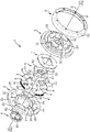
- FIG. 2 is an exploded perspective view (as seen from the X1 side) of the reclining device.
- FIG. 3 is an exploded perspective view (as seen from the X2 side) of the reclining device.
- FIG. 4 is a front view of the reclining device (as viewed from the X2 side).
- FIG. 5 is a cross-sectional view of the reclining device (a cross-sectional view taken along line VV in FIG. 4).
- FIG. 6 is a partial cross-sectional view of the reclining device (locked state) viewed from the X1 side.
- FIG. 7 is a partial cross-sectional view of the reclining device (unlocked state) viewed from the X1 side.
- FIG. 8 is an enlarged schematic diagram (an enlarged schematic diagram of area Ar1 in FIG. 6) of the reclining device showing the relationship between the lock gear, the internal gear, and the guide portion (guide bracket).
- FIG. 9 is a schematic diagram for explaining the operation of the reclining device. Section (a) is a schematic diagram of the main part of the reclining device for explaining the movement of the lock gear from the unlocked position to the locked position. (b) is a schematic view of the main part of the reclining device when the lock gear is set to the lock position.
- FIG. 1 is a partial cross-sectional view of the reclining device (unlocked state) viewed from the X1 side.
- FIG. 8 is an enlarged schematic diagram (an enlarged schematic diagram of area Ar1 in FIG. 6) of the reclining device showing the relationship between the lock gear, the internal gear, and the guide portion (guide bracket).
- FIG. 10 is a schematic diagram of the main part of the reclining device for explaining the movement of the lock gear from the unlocked position to the locked position.
- FIG. 11 is a partial cross-sectional view corresponding to FIG. 6 showing the locked state of the reclining device according to the second embodiment.
- FIG. 12 is a partial cross-sectional view corresponding to FIG. 6 showing the locked state of the reclining device according to the third embodiment.
- FIG. 13 is an enlarged view of the essential part of FIG. 6 showing the reclining device.
- FIG. 1 to 5 show a reclining device 1 according to a first embodiment of the present invention, wherein FIG. 1 is a perspective view, FIGS. 2 and 3 are exploded perspective views, FIG. 4 is a plan view, and FIG. 5 is a sectional view showing the reclining device 1 respectively.
- the reclining device 1 is applied, for example, to an automobile seat (not shown).
- an automobile seat includes a seat cushion that supports the buttocks of a person sitting on the seat, and a seat back that serves as a backrest.
- the reclining device 1 is a seat device that is interposed between a seat cushion and a seat back to change the inclination angle of the seat back with respect to the seat cushion.
- the symbol X indicates a virtual axis (hereinafter referred to as the X-axis) corresponding to the rotation axis of tilting of the seatback.
- the reclining device 1 has a disk-like shape that is flattened in the X-axis direction, and is interposed between the left and right side surfaces of the seat cushion frame and the seatback frame.
- the X1 side in FIG. 1 is the seat back frame (Sb) side
- the X2 side is the seat cushion frame (Sc) side.
- the reclining device 1 includes a guide bracket 2 fixed to the seat cushion frame (Sc), an internal gear 3 attached to the seat back frame (Sb), the guide bracket 2 and the interface. It is composed of a plurality (four in this example) of lock gears 4, rotating cams 5, lock springs 6, and plates 7, which are incorporated between null gears 3, and a mounting ring 8 that holds them together.
- the guide bracket 2 is fixed to the seat cushion frame (Sc)
- the internal gear 3 is fixed to the seatback frame (Sb).
- a reverse configuration that is, a configuration in which the internal gear 3 is fixed to the seat cushion frame (Sc) and the guide bracket is fixed to the seat back frame (Sb), may also be used.
- the guide bracket 2 is an annular plate member having a substantially circular opening 20 at its center.
- Four guide portions 22 (sometimes referred to as first guide portion 22A to fourth guide portion 22D) consisting of convex portions projecting in the X1 direction from the same surface are provided on the X1 side surface of the guide bracket 2.
- Each of the guide portions 22 has the same sector shape in front view from the X1 side.
- Each guide portion 22 is arranged at equal intervals around the opening portion 20 . Between adjacent guide portions 22, groove portions 23 extending in a cross shape in the radial direction of the guide bracket 2 are formed.
- a lock gear 4 (sometimes referred to as a first lock gear 4A to a fourth lock gear 4D) is arranged in each groove 23 .
- the lock gear 4 is a plate-shaped member in which both side surfaces 40a in the width direction, which is the direction in which the external teeth 41 are arranged, are parallel to the side surfaces 22a (see FIG. 8) of the guide portion 22. As shown in FIG.
- the lock gear 4 is slidably provided in the radial direction of the guide bracket 2 along the side surface 22 a of the adjacent guide portion 22 .
- the outer peripheral side of the lock gear 4 that is, the portion between the adjacent guide portions 22 and corresponding to the radially outer side of the guide bracket 2 is formed in an arc shape, and can mesh with the internal teeth 31 of the internal gear 3 at this portion.
- external teeth 41 are provided along the arc.
- a cam groove 42 is provided on the inner peripheral side of the lock gear 4 , that is, on the portion corresponding to the radially inner side of the guide bracket 2 .
- a rotating cam 5 is arranged radially inside each lock gear 4 .
- the rotating cam 5 is a plate member having a substantially swastika shape when viewed from the front from the X2 side, having four cam portions 52 spirally extending in the circumferential direction from four positions on the outer peripheral surface.
- a boss portion 50 is provided at the center of the surface of the rotating cam 5 on the X2 side, and a shaft hole 51 having a rectangular cross section is formed at the center of the boss portion 50 .
- An operation shaft (not shown) to which an operation lever (not shown) is fixed is inserted into the shaft hole 51 .
- the boss portion 50 of the rotating cam 5 is inserted into the opening 20 of the guide bracket 2.
- a lock spring 6 made of a spiral spring is interposed between the outer peripheral surface of the boss portion 50 and the inner peripheral surface of the guide bracket 2 (the inner surface of the opening portion 20).
- Hook portions 61 and 62 are formed at the inner peripheral end and the outer peripheral end of the lock spring 6 .
- the hook portion 61 at the inner peripheral end is engaged with the notch portion 51 a formed in the boss portion 50 of the rotary cam 5
- the hook portion 62 at the outer peripheral end is engaged with the opening portion 20 of the guide bracket 2 .
- the internal gear 3 has a bottomed cylindrical shape that is flat in the X-axis direction and has the same outer diameter as the guide bracket 2 .
- the inner peripheral surface of the internal gear 3 is provided with internal teeth 31 that can mesh with the external teeth 41 of the lock gear 4 .
- the internal gear 3 is superimposed on the guide bracket 2 with the surface (annular surface) on the opening side (X2 side) abutting against the surface on the X1 side of the guide bracket 2.
- the guide portion 22 of the guide bracket 2, the lock gear 4 and the rotary cam 5 are arranged inside the internal gear 3 as shown in FIG.
- FIG. 6 is a partial cross-sectional view of the reclining device 1 (locked state described later) viewed from the X2 side.
- the guide bracket 2 and the internal gear 3 are relatively rotatably integrated by the mounting ring 8 with the lock gear 4, the rotating cam 5, the lock spring 6 and the plate 7 described later arranged inside.
- the mounting ring 8 has a cylindrical peripheral surface portion 80 and an annular bottom surface portion 81 which is continuously provided inside one end of the cylindrical peripheral surface portion 80 .
- the mounting ring 8 is fitted onto the guide bracket 2 and the internal gear 3 so that the end surface of the internal gear 3 on the X1 side contacts the annular bottom portion 81 .
- the annular bottom portion 81 is fixed to the guide bracket 2 by welding or the like so as to allow the internal gear 3 to rotate.
- the lock gear 4 is slidable in the radial direction of the guide bracket 2 along the guide portion 22 (side surface 22a). As a result, the lock gear 4 is in a locked position (position shown in FIG. 6) in which it meshes with the internal gear 3, and retreats inside the internal gear 3 from the locked position to be in a non-engagement state with the internal gear 3. It can be displaced (advance/retreat) to the unlocked position (the position shown in FIG. 7).
- the rotating cam 5 is urged counterclockwise (in the direction of arrow R in FIG. 6) in plan view from the X1 side due to the elastic force of the lock spring 6 .
- the lock gear 4 is pressed radially outward (radially outward with respect to the internal gear 3 ) by the cam portion 52 of the rotating cam 5 . That is, the lock gear 4 is biased by the lock spring 6 so as to be placed at the locked position.
- a clockwise rotation (clockwise in a plan view from the X1 side/in the direction of arrow F in FIG. 7) is applied to the rotating cam 5 against the biasing force of the lock spring 6.
- the cam portion 52 of the rotating cam 5 intervenes in the cam groove 42 of the lock gear 4, and the intervention of the cam portion 52 causes the lock gear 4 to move radially inward (of the internal gear 3) as indicated by the white arrow in FIG. radially inward).
- the lock gear 4 is displaced from the locked position to the unlocked position.
- the rotating cam 5 is integrated with the plate 7 and is rotatable around a boss formed on the outer periphery of the shaft hole 30 of the internal gear 3 .
- a plurality of positioning protrusions 32 protruding in the X1 direction are formed around the shaft hole 30. is provided in A plurality of positioning protrusions 24 protruding in the X2 direction are provided around the opening 20 on the X2 side (seat cushion frame (Sc) side) surface of the guide bracket 2 .
- the convex portion 32 of the internal gear 3 is formed in a positioning hole formed in the seat back frame (Sb), and the convex portion 24 of the guide bracket 2 is formed in a positioning hole formed in the seat cushion frame (Sc). are inserted between both frames (Sb, Sc).
- An operation shaft (not shown) to which an operation lever (not shown) is fixed is inserted into the center of the reclining device 1 interposed between the frames (Sb, Sc).
- the operating shaft has an end portion with a rectangular cross section, and this end portion is inserted into the shaft hole 51 of the rotary cam 5 .
- Each lock gear 4 is held at the lock position by the elastic force of the lock spring 6 when the operation lever is not operated. That is, the reclining device 1 is kept in a locked state (the state shown in FIG. 6) in which relative rotation between the guide bracket 2 and the internal gear 3 is prevented, whereby the seat back is tilted at a predetermined angle with respect to the seat cushion. fixed at an angle.
- each lock gear 4 is pulled from the locked position to the unlocked position, and the reclining device 1 moves between the guide bracket 2 and the internal gear. 3 is in an unlocked state that allows relative rotation with 3.
- the lock gear 4 is returned to the locked position by the elastic force of the lock spring 6 (the reclining device 1 is returned to the locked state).
- the seat back is fixed at the tilt angle after the angle change.
- the guide bracket 2 is provided so that switching between the locked state and the unlocked state, that is, the sliding displacement (advance and retreat operation) of each lock gear 4 between the locked position and the unlocked position is performed smoothly.
- a small gap is set between the guide portion 22 (side surface 22a) and the lock gear 4 (side surface 40a). In the conventional reclining device, this gap causes rattling of the seat back and collision noise (abnormal noise) between the lock gear and the guide surface caused by the rattling.
- the reclining device 1 employs the following configuration.
- FIG. 8 is an enlarged schematic view of the main parts of the reclining device 1 showing the relationship between the lock gear 4, the internal gear 3, and the guide portion 22 (guide bracket 2). Specifically, the first guide portion 22A and the first and second lock gears 4A and 4B located on both sides of the first guide portion 22A in the state where the lock gear 4 is set to the lock position are shown in the area Ar1 indicated by the two-dot chain line in FIG. 1 is a schematic diagram showing a portion of FIG.
- the external tooth 41 of the first lock gear 4A has a tooth surface 41a (guide portion side tooth surface) on the first guide portion 22A side in the tooth thickness direction (horizontal direction in FIG. 8). 41a) and the tooth surface 31a of the internal tooth 31 facing it, the first guide portion 22A side has a notched shape.
- the external teeth 41 serve as first guides for the non-standard teeth 41'.
- the portion 22A side has a shape in which a predetermined dimension is cut in parallel with the guide portion side tooth surface 41a' of the non-standard tooth 41'. Therefore, the external teeth 41 have a shape whose tooth height dimension is smaller than that of the internal teeth 31 in appearance.
- the end of the first lock gear 4A on the side of the first guide portion 22A protrudes toward the first guide portion 22A from the root position Ta of the external tooth 41 positioned at the end on the side of the first guide portion 22A.
- the end face of the protruding portion 44, that is, the side surface 40a of the first lock gear 4A is the guided surface of the first guide portion 22A (side surface 22a).
- the end of the second lock gear 4B on the side of the first guide portion 22A extends from the root position Ta of the external tooth 41 located on the end of the first guide portion 22A to the first guide portion.
- the end face (side surface 40a) of the protruding portion 44 is a surface to be guided by the first guide portion 22A (side surface 22a).
- the first and second lock gears 4A and 4B are locked as shown in FIGS.
- the first guide portion 22A is in contact with the first and second lock gears 4A and 4B from both sides thereof, that is, the first guide portion. 22A is sandwiched from both sides by the first and second lock gears 4A and 4B.
- the first and second lock gears 4A, 4B are displaced from the unlocked position to the locked position by the elastic force of the lock spring 6 (arrow 1 in FIG. 9A), at a certain stage, for example, the first The external teeth 41 of the 1-lock gear 4A catch the internal teeth 31 of the internal gear 3, and the tooth surfaces 41b of the external teeth 41 opposite to the guide portion contact the tooth surfaces 31a of the internal teeth 31 facing them.
- the external teeth 41 of the second lock gear 4B are not in contact with the internal teeth 31 at this stage, as shown in FIG.
- the first lock gear 4A whose tooth surface 41b on the side opposite to the guide portion is in contact with the internal tooth 31, moves obliquely radially outward along the tooth surface 31a of the internal tooth 31, thereby moving toward the first guide portion 22A. side and abut against the first guide portion 22A before reaching the lock position (arrow 2 in FIG. 9A).
- the external teeth 41 of the second lock gear 4B do not come into contact with the internal teeth 31 even at this stage.
- first lock gear 4A Since the first lock gear 4A is pressed by the elastic force of the lock spring 6, it moves further along the first guide portion 22A to the lock position.
- the internal gear 3 moves relative to the guide bracket 2. substantially counterclockwise (arrow 4 in FIG. 9(a)).
- the tooth surface 31a of the internal tooth 31 contacts the anti-guide portion side tooth surface 41b of the second lock gear 4B, and the second lock gear 4B is displaced together with the internal gear 3 toward the first guide portion 22A (FIG. 9).
- the first and second guide portions 22A and 22B abut on the first guide portion 22A as shown in FIG.
- the first guide portion 22A is sandwiched from both sides by the first and second guide portions 22A and 22B.
- FIG. 9(a) and 9(b) show that in the process of displacing the first and second lock gears 4A and 4B from the unlocked position to the locked position, first, the outer teeth 41 of the first lock gear 4A move first, leading to the inner teeth. This is the case where the tooth 31 is caught (engaged).
- FIG. 9(b) shows the state when the first and second lock gears 4A and 4B are set to the locked position, except that the direction of movement of the null gear 3 is reversed from that shown in FIG. 9(a). Equivalent to the state shown.
- the phase (positional relationship) between the external teeth 41 and the internal teeth 31 changes depending on the inclination angle of the seat back, that is, the relative positions of the internal gear 3 and the lock gear 4 in the rotational direction.
- the external teeth 41 are constantly displaced from the unlocked position to the locked position.
- the non-guide portion side tooth surface 41b comes into contact with the tooth surface 31a of the internal tooth 31 first, and the guide portion side tooth surface 41a does not contact the tooth surface 31a of the internal tooth 31 first. Therefore, when switching from the unlocked state to the locked state, the first and second lock gears 4A and 4B are always engaged as shown in FIGS. 9A and 9B or FIGS. It will move as shown in (b).
- the first and second lock gears 4A and 4B are positioned on both sides of the first guide portion 22A positioned therebetween. , and this contact state is maintained during the locked state. Therefore, the relative displacement between the guide bracket 2 and the internal gear 3 is more reliably locked, and the rattling of the seat back and the collision noise (abnormal noise) between the lock gear 4 and the guide portion 22 caused by the rattling are prevented. definitely suppressed.
- the first and second lock gears 4A and 4B move from the unlock position to the lock position.
- the side surfaces 40a of the first and second lock gears 4A, 4B can be easily brought closer to the side surface 22a of the first guide portion 22A. Therefore, the gap between the first and second lock gears 4A, 4B and the first guide portion 22A can be eliminated more reliably.
- a pair of locking structures including the first guide 22A and a pair of lock gears 4A and 4B arranged on both sides thereof (area Ar1 indicated by a two-dot chain line in FIG. 6)
- the locking structure in the present invention is not limited to one set.
- a pair of locking structures (area Ar2 indicated by two-dot chain lines in FIG. ) is more preferable.
- the reclining device 1 according to the second embodiment is intended to solve the following problems of the first embodiment. First, this problem will be described with reference to FIG. 13 .
- FIG. 13 is an enlarged view of a main part (enlarged view of a main part of FIG. 6) showing the first lock gear 4A and the internal gear 3 of the reclining device 1 of the first embodiment. is shown.
- the external teeth 41 of the first lock gear 4A mesh with the internal teeth 31 of the internal gear 3.
- the tooth surface 41b of the external tooth 41 on the side opposite to the guide portion contacts the tooth surface 31a of the internal tooth 31, and the tooth surface 41a on the side of the external tooth 41 and the tooth surface of the internal tooth 31 contact each other.
- 31a is formed with a gap (see FIG. 8).
- the angle ⁇ is As shown in FIG. 13, the width direction (left and right direction in FIG. 13) central portion of the first lock gear 4A is maximum, and it decreases toward both width direction end portions. Approach the angle parallel to D1. Therefore, at both ends in the width direction of the first lock gear 4A, when switching from the locked state to the unlocked state, the tooth surfaces 41b of the external teeth 41 on the side opposite to the guide portion are caught by the internal teeth 31, and an extra operating force is required for unlocking. Moreover, abnormal noise is generated when the meshing state between the internal teeth 31 and the external teeth 41 is released. This tendency becomes more conspicuous when meshing at the ends becomes stronger due to variations in processing.
- the tooth surface 41b on the side opposite to the guide portion of the external tooth 41 of the first lock gear 4A is notched.
- the external tooth 41 has a shape in which the tooth surface 41a on the side of the guide portion is originally notched (see FIG. 8)
- the tooth surface 41b on the side opposite to the guide portion is notched, the external tooth 41 can be The height dimension is significantly reduced, and it becomes difficult to stably maintain the meshing state between the external teeth 41 and the internal teeth 31, that is, to maintain the locking strength of the reclining device 1.
- the reclining device 1 of the second embodiment further has the following configuration in order to solve such problems.
- FIG. 11 is a partial cross-sectional view corresponding to FIG. 6, showing the locked state of the reclining device 1 according to the second embodiment.
- the reclining device 1 according to the second embodiment differs from the first embodiment in the following points in the configuration of the first lock gear 4A and the second lock gear 4B. Also, the same configuration as the first guide portion 22A and the second guide portion 22B is applied to the third guide portion 22C and the third lock gear 4C and the fourth lock gear 4D located on both sides thereof. Other configurations are the same as those of the reclining device 1 of the first embodiment.
- one of the external teeth 41 located at the center in the alignment direction is set as a reference external tooth 41R, and the guide portion side area Ar4 is defined by the reference external tooth 41R as a boundary.
- the arrangement pitch of the external teeth 41 differs between the region Ar3 opposite to the guide portion and the region Ar3 opposite to the guide portion.
- the arrangement pitch of the external teeth 41 is set narrower than the arrangement pitch of the internal teeth 31 so that the external teeth 41 generally approach the reference external teeth 41R.
- the arrangement pitch of the external teeth 41 is set wider than the arrangement pitch of the internal teeth 31 so that the external teeth 41 are generally separated from the reference external teeth 41R.
- the second lock gear 4B is constructed similarly to the first lock gear 4A.
- the third and fourth lock gears 4C and 4D are constructed similarly to the first and second lock gears 4A and 4B.
- the arrangement pitch of the internal teeth 31 in the non-guide portion side area Ar3 can be set to be constant (equal pitch), or to be gradually narrowed from the reference external tooth 41R side toward the non-guide portion side.
- the arrangement pitch of the internal teeth 31 belonging to the guide portion side area Ar4 can be set to be constant (equidistant pitch) or to gradually widen from the reference external tooth 41R side toward the guide portion side. This point also applies to the second to fourth lock gears 4B to 4D.
- the external teeth of the end of the first lock gear 4A (the left end in FIG. 11) and the vicinity thereof on the side opposite to the guide portion are displaced.
- a gap S is formed between the tooth surface 41 b on the side opposite to the guide portion 41 and the tooth surface 31 a of the internal tooth 31 .
- the gap S is formed even if the tooth surface 41b on the side opposite to the guide portion of the outer tooth 41 of the first lock gear 4A is not cut.
- the reclining device 1 of the second embodiment while stably maintaining the meshing state between the external teeth 41 and the internal teeth 31 in the locked state, the external teeth 41 are shifted from the internal teeth when switching from the locked state to the unlocked state. It is possible to suppress or eliminate the phenomenon of being caught in 31 .
- one external tooth 41 located at the center in the direction of arrangement thereof is the reference external tooth 41R.
- the reference external tooth 41R is not limited to the external tooth 41 positioned at the center.
- the central external tooth 41 is used as the reference external tooth 41R, the external tooth 41 belonging to the anti-guide portion side area Ar3 and the external tooth 41 belonging to the guide portion side area Ar4 are regarded as the external tooth 41. It is possible to achieve well-balanced meshing while avoiding interference with the internal teeth 31. - ⁇ Therefore, in the configuration of the second embodiment, among the external teeth 41 of the lock gear 4, it is preferable to use the central external tooth 41 in the alignment direction or the external tooth 41 in the vicinity thereof as the reference external tooth 41R.
- FIG. 12 is a partial cross-sectional view corresponding to FIG. 6, showing the locked state of the reclining device 1 according to the third embodiment.
- the reclining device 1 according to the third embodiment also solves the problems of the first embodiment.
- the reclining device 1 according to the third embodiment also differs from the first embodiment in that the configurations of the first lock gear 4A and the second lock gear 4B are different, and the third guide portion 22C and the third and fourth
- the basic configuration is common to that of the reclining device 1 of the first embodiment, except that the lock gears 4C and 4D have the same configuration as the first guide portion 22A and the second guide portion 22B.
- the external tooth 41 located closest to the first guide portion 22A side is referred to as the first external tooth 41N, and is called the first external tooth 41N.
- the external tooth 41 positioned on the side is called the n-th external tooth 41F.
- the arrangement pitch of the external teeth 41 of the first lock gear 4A is constant (equal pitch).
- the tooth flank 41b of the first outer tooth 41N on the side opposite to the guide portion and the tooth flank 31a of the inner tooth 31 facing the first outer tooth 41N are in contact with each other, and The arrangement pitch is set so that a gap S is formed between the tooth surface 41 b of the outer tooth 41 ⁇ /b>F on the side opposite to the guide portion and the inner tooth 31 of the inner tooth 31 .
- the third and fourth lock gears 4C and 4D are constructed similarly to the first and second lock gears 4A and 4B.
- the n-th outer tooth 41F and the non-guide portion side tooth surface 41b of the adjacent outer tooth 41 and the inner tooth A gap S is formed between the tooth surface 31a of the tooth 31 and the tooth surface 31a.
- the gap S is formed even if the tooth surface 41b on the side opposite to the guide portion of the outer tooth 41 of the first lock gear 4A is not cut. Therefore, in the reclining device 1 of the third embodiment, similarly to the second embodiment, while stably maintaining the meshing state between the external teeth 41 and the internal teeth 31 in the locked state, it is possible to shift from the locked state to the unlocked state. It is possible to suppress or eliminate the phenomenon that the external teeth 41 are caught by the internal teeth 31 at the time of switching.
- the reclining device 1 described above is an example of a preferred embodiment of the reclining device according to the present invention, and its specific configuration can be changed as appropriate without departing from the gist of the present invention. For example, it is possible to employ the following configuration.
- the first guide portion 22A side of the standard external tooth 41' (virtual line in FIG. 8) is the guide portion side tooth surface 41a'. It has a shape in which a predetermined dimension is notched in parallel.
- the specific shape of the external teeth 41 is not limited to this. In short, any shape may be used as long as a gap is formed between the guide portion side tooth surface 41a and the tooth surface 31a of the internal tooth 31 in the locked state.
- the shape of the external teeth 41 of the first and second lock gears 4A and 4B located on both sides of the first guide portion 22A is necessarily symmetrical with respect to the guide portion 22 (mirror image relationship). , and can be changed as appropriate.
- the operation difference (variation) between the pair of lock gears 4 positioned on both sides of the guide portion 22 can be reduced, contributing to smooth switching between the locked state and the unlocked state.
- the external teeth 41 of the first and second lock gears 4A, 4B can ensure the same tooth surface strength and uniform durability.
- the configuration according to the present invention (the configuration shown in FIG. 8) is applied to the first guide portion 22A and the first lock gear 4A and the second lock gear 4B located on both sides thereof. (ie, employs a set of locking structures).
- the present invention is not limited to this, and the portion of the area Ar2 indicated by the two-dot chain line in FIG. , a similar configuration may be applied (a second set of locking structures may be employed).
- the present invention is also applicable to a reclining device having three lock gears 4 .
- the two lock gears 4 positioned on both sides of one guide portion 22 are configured according to the present invention (configuration shown in FIG. 8), and the outer teeth 41 of the remaining lock gears 4 are shaped like the inner teeth 31.
- the present invention can also be applied to a reclining device having five or more lock gears 4 .
- the reclining device 1 applied to an automobile seat has been described, but the reclining device of the present invention is not limited to automobile seats, and can be used in vehicles other than automobiles such as trains, aircraft, ships, offices, It can be applied to various sheets such as for home use.
- a reclining device includes a guide bracket fixed to one side of a seat cushion and a seat back, and a guide bracket fixed to the other side of the seat cushion and the seat back, with respect to the guide bracket. and an internal gear provided to be relatively rotatable on the guide bracket, and an internal gear provided on both sides of a guide portion provided on the guide bracket so as to move forward and backward along the guide portion, and mesh with the internal teeth of the internal gear.
- at least a pair of lock gears each having a possible external tooth, a lock position for locking the relative rotation by meshing the external tooth with the internal tooth, and an unlock position for releasing the lock. and a cam displaced along the guide portion.
- a gap is formed between the outer teeth of the pair of lock gears and the inner teeth of the internal gear in a state in which the lock gears are arranged at the lock position.
- the tooth flank on the side of the guide portion has a notched shape.
- this reclining device it is possible to suppress rattling of the seat back and generation of abnormal noise without increasing cost or size.
- the shape of the external teeth of the first lock gear and the second lock gear is preferably a shape symmetrical with respect to the guide portion.
- the outer tooth positioned closest to the guide portion has a portion projecting from the root of the tooth toward the guide portion.
- the reclining device of the present invention may include two sets of the pair of lock gears, that is, a total of four lock gears, and the four lock gears may be arranged at equal intervals in the circumferential direction of the internal gear. .
- the above reclining device may include a total of three lock gears including the pair of lock gears, and the three lock gears may be arranged at regular intervals in the circumferential direction of the internal gear. .
- the internal gear has the internal teeth arranged along the cylindrical inner peripheral surface, and each of the pair of lock gears advances and retreats inside the internal gear in the radial direction.
- the external teeth are arranged along a circular arc so as to be able to be provided and can mesh with the internal teeth of a partial region of the internal gear, and among the external teeth of the lock gear, the external teeth other than the external teeth located at both ends
- One of the external teeth is used as a reference external tooth, and the arrangement pitch of the external teeth is set so that the external teeth belonging to the area on the side opposite to the guide part than the reference external tooth are closer to the reference external tooth side than the internal teeth.
- the arrangement pitch of the external teeth is set narrower than the arrangement pitch of the internal teeth so that the external teeth belonging to the region closer to the guide part than the reference external teeth are separated from the reference external teeth. It may be set wider than the pitch.
- the reference external tooth may be an external tooth positioned at or near the center in the alignment direction among the external teeth of the lock gear.
- the external teeth belonging to the region opposite to the guide portion and the external teeth belonging to the region facing the guide portion can be meshed in good balance while avoiding interference between the external teeth and the internal teeth. It becomes possible.
- the internal gear has the internal teeth arranged along the cylindrical inner peripheral surface, and each of the pair of lock gears is radially movable inside the internal gear. provided and arranged along an arc so as to be able to mesh with the internal teeth of a partial region of the internal gear;
- the outer teeth of the lock gear are arranged at equal pitches, and the outer teeth of the lock gear are arranged at the same pitch, and the outer teeth of the lock gear are arranged at the same pitch. position, the tooth surface of the first outer tooth on the side opposite to the guide portion and the tooth surface of the inner tooth are in contact with each other, and the tooth surface on the side opposite to the guide portion of the n-th outer tooth and the inner tooth surface are in contact with each other.
- the arrangement pitch may be set such that a gap is formed between the tooth surfaces of the teeth.
Landscapes
- Engineering & Computer Science (AREA)
- Aviation & Aerospace Engineering (AREA)
- Transportation (AREA)
- Mechanical Engineering (AREA)
- Health & Medical Sciences (AREA)
- Dentistry (AREA)
- General Health & Medical Sciences (AREA)
- Chairs For Special Purposes, Such As Reclining Chairs (AREA)
Priority Applications (4)
| Application Number | Priority Date | Filing Date | Title |
|---|---|---|---|
| JP2023522657A JPWO2022244731A1 (https=) | 2021-05-18 | 2022-05-16 | |
| US18/555,763 US20240208373A1 (en) | 2021-05-18 | 2022-05-16 | Reclining device |
| DE112022002629.4T DE112022002629T5 (de) | 2021-05-18 | 2022-05-16 | Neigungsverstellvorrichtung |
| CN202280031998.4A CN117222347A (zh) | 2021-05-18 | 2022-05-16 | 倾斜装置 |
Applications Claiming Priority (2)
| Application Number | Priority Date | Filing Date | Title |
|---|---|---|---|
| JP2021-083874 | 2021-05-18 | ||
| JP2021083874 | 2021-05-18 |
Publications (1)
| Publication Number | Publication Date |
|---|---|
| WO2022244731A1 true WO2022244731A1 (ja) | 2022-11-24 |
Family
ID=84140497
Family Applications (1)
| Application Number | Title | Priority Date | Filing Date |
|---|---|---|---|
| PCT/JP2022/020388 Ceased WO2022244731A1 (ja) | 2021-05-18 | 2022-05-16 | リクライニング装置 |
Country Status (5)
| Country | Link |
|---|---|
| US (1) | US20240208373A1 (https=) |
| JP (1) | JPWO2022244731A1 (https=) |
| CN (1) | CN117222347A (https=) |
| DE (1) | DE112022002629T5 (https=) |
| WO (1) | WO2022244731A1 (https=) |
Citations (3)
| Publication number | Priority date | Publication date | Assignee | Title |
|---|---|---|---|---|
| JPH01169149U (https=) * | 1988-05-12 | 1989-11-29 | ||
| JP2012532062A (ja) * | 2009-07-09 | 2012-12-13 | カイパー ゲーエムベーハー ウント コンパニー カーゲー | 車両シートのための取付構造 |
| JP2013100021A (ja) * | 2011-11-08 | 2013-05-23 | Shiroki Corp | リクライニング装置 |
Family Cites Families (7)
| Publication number | Priority date | Publication date | Assignee | Title |
|---|---|---|---|---|
| JP2002101993A (ja) * | 2000-09-29 | 2002-04-09 | Delta Kogyo Co Ltd | シートのリクライナ構造 |
| JP3804597B2 (ja) * | 2002-09-20 | 2006-08-02 | トヨタ紡織株式会社 | リクライニング装置 |
| JP5125836B2 (ja) | 2008-07-15 | 2013-01-23 | アイシン精機株式会社 | シートリクライニング装置 |
| JP5668702B2 (ja) * | 2012-01-26 | 2015-02-12 | アイシン精機株式会社 | 車両用シートリクライニング装置 |
| KR101752738B1 (ko) * | 2016-02-29 | 2017-06-30 | 주식회사 서연씨엔에프 | 차량시트용 고강성 리클라이너 |
| JP2018083579A (ja) * | 2016-11-25 | 2018-05-31 | トヨタ紡織株式会社 | 減速装置 |
| CN209856340U (zh) * | 2019-04-04 | 2019-12-27 | 重庆巨泰机械有限公司 | 一种带啮合外齿的从动齿轮 |
-
2022
- 2022-05-16 JP JP2023522657A patent/JPWO2022244731A1/ja active Pending
- 2022-05-16 WO PCT/JP2022/020388 patent/WO2022244731A1/ja not_active Ceased
- 2022-05-16 CN CN202280031998.4A patent/CN117222347A/zh active Pending
- 2022-05-16 DE DE112022002629.4T patent/DE112022002629T5/de active Pending
- 2022-05-16 US US18/555,763 patent/US20240208373A1/en active Pending
Patent Citations (3)
| Publication number | Priority date | Publication date | Assignee | Title |
|---|---|---|---|---|
| JPH01169149U (https=) * | 1988-05-12 | 1989-11-29 | ||
| JP2012532062A (ja) * | 2009-07-09 | 2012-12-13 | カイパー ゲーエムベーハー ウント コンパニー カーゲー | 車両シートのための取付構造 |
| JP2013100021A (ja) * | 2011-11-08 | 2013-05-23 | Shiroki Corp | リクライニング装置 |
Also Published As
| Publication number | Publication date |
|---|---|
| US20240208373A1 (en) | 2024-06-27 |
| JPWO2022244731A1 (https=) | 2022-11-24 |
| DE112022002629T5 (de) | 2024-03-14 |
| CN117222347A (zh) | 2023-12-12 |
Similar Documents
| Publication | Publication Date | Title |
|---|---|---|
| JP4308859B2 (ja) | リクライニング装置 | |
| JP5125836B2 (ja) | シートリクライニング装置 | |
| EP2062505B1 (en) | Recliner adjuster mechanism for a seat | |
| JP5668702B2 (ja) | 車両用シートリクライニング装置 | |
| EP2293960B1 (en) | Disc recliner with integral travel stops | |
| JP5644288B2 (ja) | リクライニング装置 | |
| US7758124B2 (en) | Seat apparatus for vehicle | |
| KR101427567B1 (ko) | 웨지를 갖는 차량용 리클라이너 | |
| JP2009509596A5 (https=) | ||
| JP2009509596A (ja) | 車両シート用取り付け具 | |
| JPH09308541A (ja) | 内歯式リクライニングデバイス | |
| JP6091766B2 (ja) | リクライニング装置 | |
| KR101393603B1 (ko) | 웨지를 갖는 차량용 라운드 리클라이너 | |
| WO2022244731A1 (ja) | リクライニング装置 | |
| JP2012091624A (ja) | 車両用シートリクライニング装置 | |
| JP4336218B2 (ja) | リクライニング装置 | |
| KR101200154B1 (ko) | 차량 시트용 리클라이너 | |
| JP5556441B2 (ja) | リクライニング装置 | |
| JP7727184B2 (ja) | リクライニング装置 | |
| JP7404935B2 (ja) | 乗物用シートリクライニング装置 | |
| JP4255811B2 (ja) | リクライニング装置 | |
| WO2006088896A1 (en) | Seat recliner | |
| JP7633515B2 (ja) | リクライニング装置 | |
| JP7713810B2 (ja) | リクライニング装置 | |
| WO2025225241A1 (ja) | リクライニング装置およびシート |
Legal Events
| Date | Code | Title | Description |
|---|---|---|---|
| 121 | Ep: the epo has been informed by wipo that ep was designated in this application |
Ref document number: 22804642 Country of ref document: EP Kind code of ref document: A1 |
|
| WWE | Wipo information: entry into national phase |
Ref document number: 18555763 Country of ref document: US |
|
| WWE | Wipo information: entry into national phase |
Ref document number: 2023522657 Country of ref document: JP |
|
| WWE | Wipo information: entry into national phase |
Ref document number: 202280031998.4 Country of ref document: CN |
|
| WWE | Wipo information: entry into national phase |
Ref document number: 112022002629 Country of ref document: DE |
|
| 122 | Ep: pct application non-entry in european phase |
Ref document number: 22804642 Country of ref document: EP Kind code of ref document: A1 |