WO2022244570A1 - 冷却構造、バッテリーユニット、及び冷却構造の製造方法 - Google Patents
冷却構造、バッテリーユニット、及び冷却構造の製造方法 Download PDFInfo
- Publication number
- WO2022244570A1 WO2022244570A1 PCT/JP2022/017942 JP2022017942W WO2022244570A1 WO 2022244570 A1 WO2022244570 A1 WO 2022244570A1 JP 2022017942 W JP2022017942 W JP 2022017942W WO 2022244570 A1 WO2022244570 A1 WO 2022244570A1
- Authority
- WO
- WIPO (PCT)
- Prior art keywords
- cooling structure
- flow path
- press
- formed member
- laser
- Prior art date
Links
- 238000001816 cooling Methods 0.000 title claims abstract description 196
- 238000004519 manufacturing process Methods 0.000 title claims description 22
- 229910000831 Steel Inorganic materials 0.000 claims abstract description 83
- 239000010959 steel Substances 0.000 claims abstract description 83
- 238000007747 plating Methods 0.000 claims abstract description 74
- 239000000110 cooling liquid Substances 0.000 claims abstract description 23
- 238000003466 welding Methods 0.000 claims description 54
- 239000011324 bead Substances 0.000 claims description 40
- 239000000126 substance Substances 0.000 claims description 35
- 238000000034 method Methods 0.000 claims description 20
- 238000006243 chemical reaction Methods 0.000 claims description 17
- 238000011282 treatment Methods 0.000 claims description 15
- VYPSYNLAJGMNEJ-UHFFFAOYSA-N Silicium dioxide Chemical compound O=[Si]=O VYPSYNLAJGMNEJ-UHFFFAOYSA-N 0.000 description 47
- 230000007797 corrosion Effects 0.000 description 44
- 238000005260 corrosion Methods 0.000 description 44
- 239000002826 coolant Substances 0.000 description 33
- 229910052751 metal Inorganic materials 0.000 description 21
- 239000002184 metal Substances 0.000 description 21
- NLYAJNPCOHFWQQ-UHFFFAOYSA-N kaolin Chemical compound O.O.O=[Al]O[Si](=O)O[Si](=O)O[Al]=O NLYAJNPCOHFWQQ-UHFFFAOYSA-N 0.000 description 16
- 238000007739 conversion coating Methods 0.000 description 15
- 239000002585 base Substances 0.000 description 13
- 239000000463 material Substances 0.000 description 11
- 239000010936 titanium Substances 0.000 description 11
- 238000005304 joining Methods 0.000 description 10
- -1 alkali metal salts Chemical class 0.000 description 9
- 239000000945 filler Substances 0.000 description 8
- NBIIXXVUZAFLBC-UHFFFAOYSA-N Phosphoric acid Chemical compound OP(O)(O)=O NBIIXXVUZAFLBC-UHFFFAOYSA-N 0.000 description 7
- 125000000524 functional group Chemical group 0.000 description 7
- 150000003961 organosilicon compounds Chemical class 0.000 description 7
- 239000000377 silicon dioxide Substances 0.000 description 7
- 229910002012 Aerosil® Inorganic materials 0.000 description 6
- 239000006087 Silane Coupling Agent Substances 0.000 description 6
- CDAISMWEOUEBRE-GPIVLXJGSA-N inositol Chemical compound O[C@H]1[C@H](O)[C@@H](O)[C@H](O)[C@H](O)[C@@H]1O CDAISMWEOUEBRE-GPIVLXJGSA-N 0.000 description 6
- 229960000367 inositol Drugs 0.000 description 6
- 239000007788 liquid Substances 0.000 description 6
- CDAISMWEOUEBRE-UHFFFAOYSA-N scyllo-inosotol Natural products OC1C(O)C(O)C(O)C(O)C1O CDAISMWEOUEBRE-UHFFFAOYSA-N 0.000 description 6
- 229910052726 zirconium Inorganic materials 0.000 description 6
- 229910019142 PO4 Inorganic materials 0.000 description 5
- 229910052782 aluminium Inorganic materials 0.000 description 5
- XAGFODPZIPBFFR-UHFFFAOYSA-N aluminium Chemical compound [Al] XAGFODPZIPBFFR-UHFFFAOYSA-N 0.000 description 5
- 238000000576 coating method Methods 0.000 description 5
- 125000002887 hydroxy group Chemical group [H]O* 0.000 description 5
- 235000021317 phosphate Nutrition 0.000 description 5
- VXUYXOFXAQZZMF-UHFFFAOYSA-N titanium(IV) isopropoxide Chemical compound CC(C)O[Ti](OC(C)C)(OC(C)C)OC(C)C VXUYXOFXAQZZMF-UHFFFAOYSA-N 0.000 description 5
- 229910052720 vanadium Inorganic materials 0.000 description 5
- 125000003545 alkoxy group Chemical group 0.000 description 4
- 239000008119 colloidal silica Substances 0.000 description 4
- 229910052731 fluorine Inorganic materials 0.000 description 4
- 235000011007 phosphoric acid Nutrition 0.000 description 4
- 150000003755 zirconium compounds Chemical class 0.000 description 4
- QTBSBXVTEAMEQO-UHFFFAOYSA-N Acetic acid Chemical compound CC(O)=O QTBSBXVTEAMEQO-UHFFFAOYSA-N 0.000 description 3
- LFQSCWFLJHTTHZ-UHFFFAOYSA-N Ethanol Chemical compound CCO LFQSCWFLJHTTHZ-UHFFFAOYSA-N 0.000 description 3
- LYCAIKOWRPUZTN-UHFFFAOYSA-N Ethylene glycol Chemical compound OCCO LYCAIKOWRPUZTN-UHFFFAOYSA-N 0.000 description 3
- 229910001209 Low-carbon steel Inorganic materials 0.000 description 3
- OKKJLVBELUTLKV-UHFFFAOYSA-N Methanol Chemical compound OC OKKJLVBELUTLKV-UHFFFAOYSA-N 0.000 description 3
- 229910000147 aluminium phosphate Inorganic materials 0.000 description 3
- 125000003277 amino group Chemical group 0.000 description 3
- 150000003863 ammonium salts Chemical class 0.000 description 3
- 229910052804 chromium Inorganic materials 0.000 description 3
- 239000011651 chromium Substances 0.000 description 3
- KRKNYBCHXYNGOX-UHFFFAOYSA-N citric acid Chemical compound OC(=O)CC(O)(C(O)=O)CC(O)=O KRKNYBCHXYNGOX-UHFFFAOYSA-N 0.000 description 3
- 239000011248 coating agent Substances 0.000 description 3
- 238000004891 communication Methods 0.000 description 3
- 150000001875 compounds Chemical class 0.000 description 3
- 230000000694 effects Effects 0.000 description 3
- 238000011156 evaluation Methods 0.000 description 3
- 150000002222 fluorine compounds Chemical class 0.000 description 3
- JEIPFZHSYJVQDO-UHFFFAOYSA-N iron(III) oxide Inorganic materials O=[Fe]O[Fe]=O JEIPFZHSYJVQDO-UHFFFAOYSA-N 0.000 description 3
- VLKZOEOYAKHREP-UHFFFAOYSA-N n-Hexane Chemical compound CCCCCC VLKZOEOYAKHREP-UHFFFAOYSA-N 0.000 description 3
- 239000012071 phase Substances 0.000 description 3
- 239000010452 phosphate Substances 0.000 description 3
- LEONUFNNVUYDNQ-UHFFFAOYSA-N vanadium atom Chemical compound [V] LEONUFNNVUYDNQ-UHFFFAOYSA-N 0.000 description 3
- XLYOFNOQVPJJNP-UHFFFAOYSA-N water Substances O XLYOFNOQVPJJNP-UHFFFAOYSA-N 0.000 description 3
- BDSSZTXPZHIYHM-UHFFFAOYSA-N 2-phenoxypropanoyl chloride Chemical compound ClC(=O)C(C)OC1=CC=CC=C1 BDSSZTXPZHIYHM-UHFFFAOYSA-N 0.000 description 2
- DUFCMRCMPHIFTR-UHFFFAOYSA-N 5-(dimethylsulfamoyl)-2-methylfuran-3-carboxylic acid Chemical compound CN(C)S(=O)(=O)C1=CC(C(O)=O)=C(C)O1 DUFCMRCMPHIFTR-UHFFFAOYSA-N 0.000 description 2
- 229910002014 Aerosil® 130 Inorganic materials 0.000 description 2
- 229910002016 Aerosil® 200 Inorganic materials 0.000 description 2
- 229910002018 Aerosil® 300 Inorganic materials 0.000 description 2
- 229910002019 Aerosil® 380 Inorganic materials 0.000 description 2
- 229910002021 Aerosil® TT 600 Inorganic materials 0.000 description 2
- CIWBSHSKHKDKBQ-JLAZNSOCSA-N Ascorbic acid Chemical compound OC[C@H](O)[C@H]1OC(=O)C(O)=C1O CIWBSHSKHKDKBQ-JLAZNSOCSA-N 0.000 description 2
- CURLTUGMZLYLDI-UHFFFAOYSA-N Carbon dioxide Chemical compound O=C=O CURLTUGMZLYLDI-UHFFFAOYSA-N 0.000 description 2
- VYZAMTAEIAYCRO-UHFFFAOYSA-N Chromium Chemical compound [Cr] VYZAMTAEIAYCRO-UHFFFAOYSA-N 0.000 description 2
- RGHNJXZEOKUKBD-SQOUGZDYSA-N D-gluconic acid Chemical compound OC[C@@H](O)[C@@H](O)[C@H](O)[C@@H](O)C(O)=O RGHNJXZEOKUKBD-SQOUGZDYSA-N 0.000 description 2
- KRHYYFGTRYWZRS-UHFFFAOYSA-N Fluorane Chemical compound F KRHYYFGTRYWZRS-UHFFFAOYSA-N 0.000 description 2
- PXGOKWXKJXAPGV-UHFFFAOYSA-N Fluorine Chemical compound FF PXGOKWXKJXAPGV-UHFFFAOYSA-N 0.000 description 2
- KFZMGEQAYNKOFK-UHFFFAOYSA-N Isopropanol Chemical compound CC(C)O KFZMGEQAYNKOFK-UHFFFAOYSA-N 0.000 description 2
- QAOWNCQODCNURD-UHFFFAOYSA-L Sulfate Chemical compound [O-]S([O-])(=O)=O QAOWNCQODCNURD-UHFFFAOYSA-L 0.000 description 2
- GWEVSGVZZGPLCZ-UHFFFAOYSA-N Titan oxide Chemical compound O=[Ti]=O GWEVSGVZZGPLCZ-UHFFFAOYSA-N 0.000 description 2
- QCWXUUIWCKQGHC-UHFFFAOYSA-N Zirconium Chemical compound [Zr] QCWXUUIWCKQGHC-UHFFFAOYSA-N 0.000 description 2
- YRKCREAYFQTBPV-UHFFFAOYSA-N acetylacetone Chemical compound CC(=O)CC(C)=O YRKCREAYFQTBPV-UHFFFAOYSA-N 0.000 description 2
- 229910052783 alkali metal Inorganic materials 0.000 description 2
- 229910052784 alkaline earth metal Inorganic materials 0.000 description 2
- 230000015572 biosynthetic process Effects 0.000 description 2
- 125000002915 carbonyl group Chemical group [*:2]C([*:1])=O 0.000 description 2
- 125000003178 carboxy group Chemical group [H]OC(*)=O 0.000 description 2
- 239000000498 cooling water Substances 0.000 description 2
- 238000005520 cutting process Methods 0.000 description 2
- 238000010586 diagram Methods 0.000 description 2
- XBDQKXXYIPTUBI-UHFFFAOYSA-N dimethylselenoniopropionate Natural products CCC(O)=O XBDQKXXYIPTUBI-UHFFFAOYSA-N 0.000 description 2
- WBFZBNKJVDQAMA-UHFFFAOYSA-D dipotassium;zirconium(4+);pentacarbonate Chemical compound [K+].[K+].[Zr+4].[Zr+4].[O-]C([O-])=O.[O-]C([O-])=O.[O-]C([O-])=O.[O-]C([O-])=O.[O-]C([O-])=O WBFZBNKJVDQAMA-UHFFFAOYSA-D 0.000 description 2
- GNTDGMZSJNCJKK-UHFFFAOYSA-N divanadium pentaoxide Chemical compound O=[V](=O)O[V](=O)=O GNTDGMZSJNCJKK-UHFFFAOYSA-N 0.000 description 2
- 239000011737 fluorine Substances 0.000 description 2
- HYBBIBNJHNGZAN-UHFFFAOYSA-N furfural Chemical compound O=CC1=CC=CO1 HYBBIBNJHNGZAN-UHFFFAOYSA-N 0.000 description 2
- 239000007789 gas Substances 0.000 description 2
- 125000003055 glycidyl group Chemical group C(C1CO1)* 0.000 description 2
- 229910052739 hydrogen Inorganic materials 0.000 description 2
- 150000004679 hydroxides Chemical class 0.000 description 2
- 239000007791 liquid phase Substances 0.000 description 2
- 150000002739 metals Chemical class 0.000 description 2
- BDAGIHXWWSANSR-UHFFFAOYSA-N methanoic acid Natural products OC=O BDAGIHXWWSANSR-UHFFFAOYSA-N 0.000 description 2
- 238000000465 moulding Methods 0.000 description 2
- UJVRJBAUJYZFIX-UHFFFAOYSA-N nitric acid;oxozirconium Chemical compound [Zr]=O.O[N+]([O-])=O.O[N+]([O-])=O UJVRJBAUJYZFIX-UHFFFAOYSA-N 0.000 description 2
- 150000002894 organic compounds Chemical class 0.000 description 2
- 229910052760 oxygen Inorganic materials 0.000 description 2
- LYTNHSCLZRMKON-UHFFFAOYSA-L oxygen(2-);zirconium(4+);diacetate Chemical compound [O-2].[Zr+4].CC([O-])=O.CC([O-])=O LYTNHSCLZRMKON-UHFFFAOYSA-L 0.000 description 2
- 150000003013 phosphoric acid derivatives Chemical class 0.000 description 2
- 229910052698 phosphorus Inorganic materials 0.000 description 2
- GQJPVGNFTLBCIQ-UHFFFAOYSA-L sodium;zirconium(4+);carbonate Chemical compound [Na+].[Zr+4].[O-]C([O-])=O GQJPVGNFTLBCIQ-UHFFFAOYSA-L 0.000 description 2
- 239000007787 solid Substances 0.000 description 2
- 239000000243 solution Substances 0.000 description 2
- 229910052719 titanium Inorganic materials 0.000 description 2
- 150000003609 titanium compounds Chemical class 0.000 description 2
- 150000003682 vanadium compounds Chemical class 0.000 description 2
- BJEPYKJPYRNKOW-REOHCLBHSA-N (S)-malic acid Chemical compound OC(=O)[C@@H](O)CC(O)=O BJEPYKJPYRNKOW-REOHCLBHSA-N 0.000 description 1
- MFWFDRBPQDXFRC-LNTINUHCSA-N (z)-4-hydroxypent-3-en-2-one;vanadium Chemical compound [V].C\C(O)=C\C(C)=O.C\C(O)=C\C(C)=O.C\C(O)=C\C(C)=O MFWFDRBPQDXFRC-LNTINUHCSA-N 0.000 description 1
- TUSDEZXZIZRFGC-UHFFFAOYSA-N 1-O-galloyl-3,6-(R)-HHDP-beta-D-glucose Natural products OC1C(O2)COC(=O)C3=CC(O)=C(O)C(O)=C3C3=C(O)C(O)=C(O)C=C3C(=O)OC1C(O)C2OC(=O)C1=CC(O)=C(O)C(O)=C1 TUSDEZXZIZRFGC-UHFFFAOYSA-N 0.000 description 1
- OWEGMIWEEQEYGQ-UHFFFAOYSA-N 100676-05-9 Natural products OC1C(O)C(O)C(CO)OC1OCC1C(O)C(O)C(O)C(OC2C(OC(O)C(O)C2O)CO)O1 OWEGMIWEEQEYGQ-UHFFFAOYSA-N 0.000 description 1
- KTXWGMUMDPYXNN-UHFFFAOYSA-N 2-ethylhexan-1-olate;titanium(4+) Chemical compound [Ti+4].CCCCC(CC)C[O-].CCCCC(CC)C[O-].CCCCC(CC)C[O-].CCCCC(CC)C[O-] KTXWGMUMDPYXNN-UHFFFAOYSA-N 0.000 description 1
- AIFLGMNWQFPTAJ-UHFFFAOYSA-J 2-hydroxypropanoate;titanium(4+) Chemical compound [Ti+4].CC(O)C([O-])=O.CC(O)C([O-])=O.CC(O)C([O-])=O.CC(O)C([O-])=O AIFLGMNWQFPTAJ-UHFFFAOYSA-J 0.000 description 1
- FOGYNLXERPKEGN-UHFFFAOYSA-N 3-(2-hydroxy-3-methoxyphenyl)-2-[2-methoxy-4-(3-sulfopropyl)phenoxy]propane-1-sulfonic acid Chemical compound COC1=CC=CC(CC(CS(O)(=O)=O)OC=2C(=CC(CCCS(O)(=O)=O)=CC=2)OC)=C1O FOGYNLXERPKEGN-UHFFFAOYSA-N 0.000 description 1
- QJZYHAIUNVAGQP-UHFFFAOYSA-N 3-nitrobicyclo[2.2.1]hept-5-ene-2,3-dicarboxylic acid Chemical compound C1C2C=CC1C(C(=O)O)C2(C(O)=O)[N+]([O-])=O QJZYHAIUNVAGQP-UHFFFAOYSA-N 0.000 description 1
- OSWFIVFLDKOXQC-UHFFFAOYSA-N 4-(3-methoxyphenyl)aniline Chemical compound COC1=CC=CC(C=2C=CC(N)=CC=2)=C1 OSWFIVFLDKOXQC-UHFFFAOYSA-N 0.000 description 1
- 229910000851 Alloy steel Inorganic materials 0.000 description 1
- RGHNJXZEOKUKBD-UHFFFAOYSA-N D-gluconic acid Natural products OCC(O)C(O)C(O)C(O)C(O)=O RGHNJXZEOKUKBD-UHFFFAOYSA-N 0.000 description 1
- WQZGKKKJIJFFOK-QTVWNMPRSA-N D-mannopyranose Chemical compound OC[C@H]1OC(O)[C@@H](O)[C@@H](O)[C@@H]1O WQZGKKKJIJFFOK-QTVWNMPRSA-N 0.000 description 1
- MMWCIQZXVOZEGG-XJTPDSDZSA-N D-myo-Inositol 1,4,5-trisphosphate Chemical compound O[C@@H]1[C@H](O)[C@@H](OP(O)(O)=O)[C@H](OP(O)(O)=O)[C@@H](O)[C@@H]1OP(O)(O)=O MMWCIQZXVOZEGG-XJTPDSDZSA-N 0.000 description 1
- FEWJPZIEWOKRBE-JCYAYHJZSA-N Dextrotartaric acid Chemical compound OC(=O)[C@H](O)[C@@H](O)C(O)=O FEWJPZIEWOKRBE-JCYAYHJZSA-N 0.000 description 1
- JZDMNWBZPLJKBT-UHFFFAOYSA-N F.[Zr] Chemical compound F.[Zr] JZDMNWBZPLJKBT-UHFFFAOYSA-N 0.000 description 1
- 239000001263 FEMA 3042 Substances 0.000 description 1
- WQZGKKKJIJFFOK-GASJEMHNSA-N Glucose Natural products OC[C@H]1OC(O)[C@H](O)[C@@H](O)[C@@H]1O WQZGKKKJIJFFOK-GASJEMHNSA-N 0.000 description 1
- 229910000677 High-carbon steel Inorganic materials 0.000 description 1
- GUBGYTABKSRVRQ-PICCSMPSSA-N Maltose Natural products O[C@@H]1[C@@H](O)[C@H](O)[C@@H](CO)O[C@@H]1O[C@@H]1[C@@H](CO)OC(O)[C@H](O)[C@H]1O GUBGYTABKSRVRQ-PICCSMPSSA-N 0.000 description 1
- 229910000954 Medium-carbon steel Inorganic materials 0.000 description 1
- UEZVMMHDMIWARA-UHFFFAOYSA-N Metaphosphoric acid Chemical compound OP(=O)=O UEZVMMHDMIWARA-UHFFFAOYSA-N 0.000 description 1
- 229910001122 Mischmetal Inorganic materials 0.000 description 1
- 239000004677 Nylon Substances 0.000 description 1
- LRBQNJMCXXYXIU-PPKXGCFTSA-N Penta-digallate-beta-D-glucose Natural products OC1=C(O)C(O)=CC(C(=O)OC=2C(=C(O)C=C(C=2)C(=O)OC[C@@H]2[C@H]([C@H](OC(=O)C=3C=C(OC(=O)C=4C=C(O)C(O)=C(O)C=4)C(O)=C(O)C=3)[C@@H](OC(=O)C=3C=C(OC(=O)C=4C=C(O)C(O)=C(O)C=4)C(O)=C(O)C=3)[C@H](OC(=O)C=3C=C(OC(=O)C=4C=C(O)C(O)=C(O)C=4)C(O)=C(O)C=3)O2)OC(=O)C=2C=C(OC(=O)C=3C=C(O)C(O)=C(O)C=3)C(O)=C(O)C=2)O)=C1 LRBQNJMCXXYXIU-PPKXGCFTSA-N 0.000 description 1
- 239000002202 Polyethylene glycol Substances 0.000 description 1
- 229920002873 Polyethylenimine Polymers 0.000 description 1
- 239000004372 Polyvinyl alcohol Substances 0.000 description 1
- 229910018557 Si O Inorganic materials 0.000 description 1
- 229910002808 Si–O–Si Inorganic materials 0.000 description 1
- 229920002125 Sokalan® Polymers 0.000 description 1
- 229920002472 Starch Polymers 0.000 description 1
- 229930006000 Sucrose Natural products 0.000 description 1
- CZMRCDWAGMRECN-UGDNZRGBSA-N Sucrose Chemical compound O[C@H]1[C@H](O)[C@@H](CO)O[C@@]1(CO)O[C@@H]1[C@H](O)[C@@H](O)[C@H](O)[C@@H](CO)O1 CZMRCDWAGMRECN-UGDNZRGBSA-N 0.000 description 1
- FEWJPZIEWOKRBE-UHFFFAOYSA-N Tartaric acid Natural products [H+].[H+].[O-]C(=O)C(O)C(O)C([O-])=O FEWJPZIEWOKRBE-UHFFFAOYSA-N 0.000 description 1
- 229910010413 TiO 2 Inorganic materials 0.000 description 1
- 229910021549 Vanadium(II) chloride Inorganic materials 0.000 description 1
- 229910021542 Vanadium(IV) oxide Inorganic materials 0.000 description 1
- XHCLAFWTIXFWPH-UHFFFAOYSA-N [O-2].[O-2].[O-2].[O-2].[O-2].[V+5].[V+5] Chemical compound [O-2].[O-2].[O-2].[O-2].[O-2].[V+5].[V+5] XHCLAFWTIXFWPH-UHFFFAOYSA-N 0.000 description 1
- QUEDYRXQWSDKKG-UHFFFAOYSA-M [O-2].[O-2].[V+5].[OH-] Chemical compound [O-2].[O-2].[V+5].[OH-] QUEDYRXQWSDKKG-UHFFFAOYSA-M 0.000 description 1
- YDHWWBZFRZWVHO-UHFFFAOYSA-H [oxido-[oxido(phosphonatooxy)phosphoryl]oxyphosphoryl] phosphate Chemical compound [O-]P([O-])(=O)OP([O-])(=O)OP([O-])(=O)OP([O-])([O-])=O YDHWWBZFRZWVHO-UHFFFAOYSA-H 0.000 description 1
- IKHGUXGNUITLKF-XPULMUKRSA-N acetaldehyde Chemical compound [14CH]([14CH3])=O IKHGUXGNUITLKF-XPULMUKRSA-N 0.000 description 1
- 235000011054 acetic acid Nutrition 0.000 description 1
- 239000002253 acid Substances 0.000 description 1
- 150000001298 alcohols Chemical class 0.000 description 1
- 150000001340 alkali metals Chemical class 0.000 description 1
- 150000001342 alkaline earth metals Chemical class 0.000 description 1
- WQZGKKKJIJFFOK-PHYPRBDBSA-N alpha-D-galactose Chemical compound OC[C@H]1O[C@H](O)[C@H](O)[C@@H](O)[C@H]1O WQZGKKKJIJFFOK-PHYPRBDBSA-N 0.000 description 1
- BJEPYKJPYRNKOW-UHFFFAOYSA-N alpha-hydroxysuccinic acid Natural products OC(=O)C(O)CC(O)=O BJEPYKJPYRNKOW-UHFFFAOYSA-N 0.000 description 1
- 229910052787 antimony Inorganic materials 0.000 description 1
- 239000007864 aqueous solution Substances 0.000 description 1
- 150000001491 aromatic compounds Chemical class 0.000 description 1
- 235000010323 ascorbic acid Nutrition 0.000 description 1
- 239000011668 ascorbic acid Substances 0.000 description 1
- 229960005070 ascorbic acid Drugs 0.000 description 1
- UNTBPXHCXVWYOI-UHFFFAOYSA-O azanium;oxido(dioxo)vanadium Chemical compound [NH4+].[O-][V](=O)=O UNTBPXHCXVWYOI-UHFFFAOYSA-O 0.000 description 1
- 230000008901 benefit Effects 0.000 description 1
- WQZGKKKJIJFFOK-VFUOTHLCSA-N beta-D-glucose Chemical compound OC[C@H]1O[C@@H](O)[C@H](O)[C@@H](O)[C@@H]1O WQZGKKKJIJFFOK-VFUOTHLCSA-N 0.000 description 1
- GUBGYTABKSRVRQ-QUYVBRFLSA-N beta-maltose Chemical compound OC[C@H]1O[C@H](O[C@H]2[C@H](O)[C@@H](O)[C@H](O)O[C@@H]2CO)[C@H](O)[C@@H](O)[C@@H]1O GUBGYTABKSRVRQ-QUYVBRFLSA-N 0.000 description 1
- 229910052796 boron Inorganic materials 0.000 description 1
- 238000005219 brazing Methods 0.000 description 1
- 159000000007 calcium salts Chemical class 0.000 description 1
- 229910052799 carbon Inorganic materials 0.000 description 1
- 239000001569 carbon dioxide Substances 0.000 description 1
- 229910002092 carbon dioxide Inorganic materials 0.000 description 1
- BVKZGUZCCUSVTD-UHFFFAOYSA-N carbonic acid Chemical compound OC(O)=O BVKZGUZCCUSVTD-UHFFFAOYSA-N 0.000 description 1
- 150000001728 carbonyl compounds Chemical class 0.000 description 1
- 239000001913 cellulose Substances 0.000 description 1
- 229920002678 cellulose Polymers 0.000 description 1
- 235000010980 cellulose Nutrition 0.000 description 1
- 230000008859 change Effects 0.000 description 1
- 150000001845 chromium compounds Chemical class 0.000 description 1
- 235000015165 citric acid Nutrition 0.000 description 1
- 239000002131 composite material Substances 0.000 description 1
- 239000000470 constituent Substances 0.000 description 1
- 238000011109 contamination Methods 0.000 description 1
- 125000004122 cyclic group Chemical group 0.000 description 1
- 230000007547 defect Effects 0.000 description 1
- 230000002950 deficient Effects 0.000 description 1
- 230000006866 deterioration Effects 0.000 description 1
- 239000001177 diphosphate Substances 0.000 description 1
- XPPKVPWEQAFLFU-UHFFFAOYSA-J diphosphate(4-) Chemical compound [O-]P([O-])(=O)OP([O-])([O-])=O XPPKVPWEQAFLFU-UHFFFAOYSA-J 0.000 description 1
- 235000011180 diphosphates Nutrition 0.000 description 1
- XPPKVPWEQAFLFU-UHFFFAOYSA-N diphosphoric acid Chemical compound OP(O)(=O)OP(O)(O)=O XPPKVPWEQAFLFU-UHFFFAOYSA-N 0.000 description 1
- 238000009713 electroplating Methods 0.000 description 1
- XYIBRDXRRQCHLP-UHFFFAOYSA-N ethyl acetoacetate Chemical compound CCOC(=O)CC(C)=O XYIBRDXRRQCHLP-UHFFFAOYSA-N 0.000 description 1
- 230000008020 evaporation Effects 0.000 description 1
- 238000001704 evaporation Methods 0.000 description 1
- 230000001747 exhibiting effect Effects 0.000 description 1
- 239000000835 fiber Substances 0.000 description 1
- 239000012530 fluid Substances 0.000 description 1
- 230000004907 flux Effects 0.000 description 1
- 235000019253 formic acid Nutrition 0.000 description 1
- 229930182830 galactose Natural products 0.000 description 1
- 239000000174 gluconic acid Substances 0.000 description 1
- 235000012208 gluconic acid Nutrition 0.000 description 1
- 239000008103 glucose Substances 0.000 description 1
- 150000004676 glycans Chemical class 0.000 description 1
- 238000000227 grinding Methods 0.000 description 1
- 229940093915 gynecological organic acid Drugs 0.000 description 1
- 239000004021 humic acid Substances 0.000 description 1
- 239000001257 hydrogen Substances 0.000 description 1
- XDBSEZHMWGHVIL-UHFFFAOYSA-M hydroxy(dioxo)vanadium Chemical compound O[V](=O)=O XDBSEZHMWGHVIL-UHFFFAOYSA-M 0.000 description 1
- 239000012535 impurity Substances 0.000 description 1
- 238000011835 investigation Methods 0.000 description 1
- 229910052742 iron Inorganic materials 0.000 description 1
- 229910052749 magnesium Inorganic materials 0.000 description 1
- 239000001630 malic acid Substances 0.000 description 1
- 235000011090 malic acid Nutrition 0.000 description 1
- 238000000691 measurement method Methods 0.000 description 1
- 230000007246 mechanism Effects 0.000 description 1
- 239000000155 melt Substances 0.000 description 1
- 229910000000 metal hydroxide Inorganic materials 0.000 description 1
- 229910044991 metal oxide Inorganic materials 0.000 description 1
- 150000004706 metal oxides Chemical class 0.000 description 1
- WSFSSNUMVMOOMR-NJFSPNSNSA-N methanone Chemical compound O=[14CH2] WSFSSNUMVMOOMR-NJFSPNSNSA-N 0.000 description 1
- 238000001000 micrograph Methods 0.000 description 1
- 150000007522 mineralic acids Chemical class 0.000 description 1
- 238000002156 mixing Methods 0.000 description 1
- 239000000203 mixture Substances 0.000 description 1
- 229910052750 molybdenum Inorganic materials 0.000 description 1
- 150000002772 monosaccharides Chemical class 0.000 description 1
- 229910052759 nickel Inorganic materials 0.000 description 1
- 229910052758 niobium Inorganic materials 0.000 description 1
- 229910052757 nitrogen Inorganic materials 0.000 description 1
- 229920001778 nylon Polymers 0.000 description 1
- 229920001542 oligosaccharide Polymers 0.000 description 1
- 150000002482 oligosaccharides Chemical class 0.000 description 1
- 150000007524 organic acids Chemical class 0.000 description 1
- 235000005985 organic acids Nutrition 0.000 description 1
- 239000012188 paraffin wax Substances 0.000 description 1
- NBIIXXVUZAFLBC-UHFFFAOYSA-K phosphate Chemical compound [O-]P([O-])([O-])=O NBIIXXVUZAFLBC-UHFFFAOYSA-K 0.000 description 1
- 150000003016 phosphoric acids Chemical class 0.000 description 1
- 239000000049 pigment Substances 0.000 description 1
- 229920002401 polyacrylamide Polymers 0.000 description 1
- 239000004584 polyacrylic acid Substances 0.000 description 1
- 229920001223 polyethylene glycol Polymers 0.000 description 1
- 229920000098 polyolefin Polymers 0.000 description 1
- 150000008442 polyphenolic compounds Chemical class 0.000 description 1
- 235000013824 polyphenols Nutrition 0.000 description 1
- 229920001282 polysaccharide Polymers 0.000 description 1
- 239000005017 polysaccharide Substances 0.000 description 1
- 229920001296 polysiloxane Polymers 0.000 description 1
- 229920002451 polyvinyl alcohol Polymers 0.000 description 1
- 159000000001 potassium salts Chemical class 0.000 description 1
- HHDOORYZQSEMGM-UHFFFAOYSA-L potassium;oxalate;titanium(4+) Chemical compound [K+].[Ti+4].[O-]C(=O)C([O-])=O HHDOORYZQSEMGM-UHFFFAOYSA-L 0.000 description 1
- 230000002250 progressing effect Effects 0.000 description 1
- 235000019260 propionic acid Nutrition 0.000 description 1
- 229940005657 pyrophosphoric acid Drugs 0.000 description 1
- IUVKMZGDUIUOCP-BTNSXGMBSA-N quinbolone Chemical compound O([C@H]1CC[C@H]2[C@H]3[C@@H]([C@]4(C=CC(=O)C=C4CC3)C)CC[C@@]21C)C1=CCCC1 IUVKMZGDUIUOCP-BTNSXGMBSA-N 0.000 description 1
- 239000011347 resin Substances 0.000 description 1
- 229920005989 resin Polymers 0.000 description 1
- 230000004044 response Effects 0.000 description 1
- 150000003839 salts Chemical class 0.000 description 1
- LIVNPJMFVYWSIS-UHFFFAOYSA-N silicon monoxide Inorganic materials [Si-]#[O+] LIVNPJMFVYWSIS-UHFFFAOYSA-N 0.000 description 1
- CMZUMMUJMWNLFH-UHFFFAOYSA-N sodium metavanadate Chemical compound [Na+].[O-][V](=O)=O CMZUMMUJMWNLFH-UHFFFAOYSA-N 0.000 description 1
- 159000000000 sodium salts Chemical class 0.000 description 1
- 229910001220 stainless steel Inorganic materials 0.000 description 1
- 239000010935 stainless steel Substances 0.000 description 1
- 239000008107 starch Substances 0.000 description 1
- 235000019698 starch Nutrition 0.000 description 1
- 239000005720 sucrose Substances 0.000 description 1
- 229920001059 synthetic polymer Polymers 0.000 description 1
- LRBQNJMCXXYXIU-NRMVVENXSA-N tannic acid Chemical compound OC1=C(O)C(O)=CC(C(=O)OC=2C(=C(O)C=C(C=2)C(=O)OC[C@@H]2[C@H]([C@H](OC(=O)C=3C=C(OC(=O)C=4C=C(O)C(O)=C(O)C=4)C(O)=C(O)C=3)[C@@H](OC(=O)C=3C=C(OC(=O)C=4C=C(O)C(O)=C(O)C=4)C(O)=C(O)C=3)[C@@H](OC(=O)C=3C=C(OC(=O)C=4C=C(O)C(O)=C(O)C=4)C(O)=C(O)C=3)O2)OC(=O)C=2C=C(OC(=O)C=3C=C(O)C(O)=C(O)C=3)C(O)=C(O)C=2)O)=C1 LRBQNJMCXXYXIU-NRMVVENXSA-N 0.000 description 1
- 235000015523 tannic acid Nutrition 0.000 description 1
- 229920002258 tannic acid Polymers 0.000 description 1
- 229940033123 tannic acid Drugs 0.000 description 1
- 239000011975 tartaric acid Substances 0.000 description 1
- 235000002906 tartaric acid Nutrition 0.000 description 1
- 238000012360 testing method Methods 0.000 description 1
- 229910052718 tin Inorganic materials 0.000 description 1
- JMXKSZRRTHPKDL-UHFFFAOYSA-N titanium ethoxide Chemical compound [Ti+4].CC[O-].CC[O-].CC[O-].CC[O-] JMXKSZRRTHPKDL-UHFFFAOYSA-N 0.000 description 1
- 229910000349 titanium oxysulfate Inorganic materials 0.000 description 1
- XJDNKRIXUMDJCW-UHFFFAOYSA-J titanium tetrachloride Chemical compound Cl[Ti](Cl)(Cl)Cl XJDNKRIXUMDJCW-UHFFFAOYSA-J 0.000 description 1
- 229910052721 tungsten Inorganic materials 0.000 description 1
- GRUMUEUJTSXQOI-UHFFFAOYSA-N vanadium dioxide Chemical compound O=[V]=O GRUMUEUJTSXQOI-UHFFFAOYSA-N 0.000 description 1
- 229910001935 vanadium oxide Inorganic materials 0.000 description 1
- JBIQAPKSNFTACH-UHFFFAOYSA-K vanadium oxytrichloride Chemical compound Cl[V](Cl)(Cl)=O JBIQAPKSNFTACH-UHFFFAOYSA-K 0.000 description 1
- VLOPEOIIELCUML-UHFFFAOYSA-L vanadium(2+);sulfate Chemical compound [V+2].[O-]S([O-])(=O)=O VLOPEOIIELCUML-UHFFFAOYSA-L 0.000 description 1
- ITAKKORXEUJTBC-UHFFFAOYSA-L vanadium(ii) chloride Chemical compound Cl[V]Cl ITAKKORXEUJTBC-UHFFFAOYSA-L 0.000 description 1
- HQYCOEXWFMFWLR-UHFFFAOYSA-K vanadium(iii) chloride Chemical compound [Cl-].[Cl-].[Cl-].[V+3] HQYCOEXWFMFWLR-UHFFFAOYSA-K 0.000 description 1
- UUUGYDOQQLOJQA-UHFFFAOYSA-L vanadyl sulfate Chemical compound [V+2]=O.[O-]S([O-])(=O)=O UUUGYDOQQLOJQA-UHFFFAOYSA-L 0.000 description 1
- 238000007740 vapor deposition Methods 0.000 description 1
- 239000001993 wax Substances 0.000 description 1
- 229910052725 zinc Inorganic materials 0.000 description 1
Images


Classifications
-
- H—ELECTRICITY
- H01—ELECTRIC ELEMENTS
- H01M—PROCESSES OR MEANS, e.g. BATTERIES, FOR THE DIRECT CONVERSION OF CHEMICAL ENERGY INTO ELECTRICAL ENERGY
- H01M10/00—Secondary cells; Manufacture thereof
- H01M10/60—Heating or cooling; Temperature control
- H01M10/65—Means for temperature control structurally associated with the cells
- H01M10/655—Solid structures for heat exchange or heat conduction
- H01M10/6556—Solid parts with flow channel passages or pipes for heat exchange
-
- H—ELECTRICITY
- H01—ELECTRIC ELEMENTS
- H01M—PROCESSES OR MEANS, e.g. BATTERIES, FOR THE DIRECT CONVERSION OF CHEMICAL ENERGY INTO ELECTRICAL ENERGY
- H01M10/00—Secondary cells; Manufacture thereof
- H01M10/60—Heating or cooling; Temperature control
- H01M10/61—Types of temperature control
- H01M10/613—Cooling or keeping cold
-
- H—ELECTRICITY
- H01—ELECTRIC ELEMENTS
- H01M—PROCESSES OR MEANS, e.g. BATTERIES, FOR THE DIRECT CONVERSION OF CHEMICAL ENERGY INTO ELECTRICAL ENERGY
- H01M10/00—Secondary cells; Manufacture thereof
- H01M10/60—Heating or cooling; Temperature control
- H01M10/62—Heating or cooling; Temperature control specially adapted for specific applications
- H01M10/625—Vehicles
-
- H—ELECTRICITY
- H01—ELECTRIC ELEMENTS
- H01M—PROCESSES OR MEANS, e.g. BATTERIES, FOR THE DIRECT CONVERSION OF CHEMICAL ENERGY INTO ELECTRICAL ENERGY
- H01M10/00—Secondary cells; Manufacture thereof
- H01M10/60—Heating or cooling; Temperature control
- H01M10/65—Means for temperature control structurally associated with the cells
- H01M10/651—Means for temperature control structurally associated with the cells characterised by parameters specified by a numeric value or mathematical formula, e.g. ratios, sizes or concentrations
-
- H—ELECTRICITY
- H01—ELECTRIC ELEMENTS
- H01M—PROCESSES OR MEANS, e.g. BATTERIES, FOR THE DIRECT CONVERSION OF CHEMICAL ENERGY INTO ELECTRICAL ENERGY
- H01M10/00—Secondary cells; Manufacture thereof
- H01M10/60—Heating or cooling; Temperature control
- H01M10/65—Means for temperature control structurally associated with the cells
- H01M10/653—Means for temperature control structurally associated with the cells characterised by electrically insulating or thermally conductive materials
-
- H—ELECTRICITY
- H01—ELECTRIC ELEMENTS
- H01M—PROCESSES OR MEANS, e.g. BATTERIES, FOR THE DIRECT CONVERSION OF CHEMICAL ENERGY INTO ELECTRICAL ENERGY
- H01M10/00—Secondary cells; Manufacture thereof
- H01M10/60—Heating or cooling; Temperature control
- H01M10/65—Means for temperature control structurally associated with the cells
- H01M10/655—Solid structures for heat exchange or heat conduction
- H01M10/6554—Rods or plates
-
- H—ELECTRICITY
- H01—ELECTRIC ELEMENTS
- H01M—PROCESSES OR MEANS, e.g. BATTERIES, FOR THE DIRECT CONVERSION OF CHEMICAL ENERGY INTO ELECTRICAL ENERGY
- H01M10/00—Secondary cells; Manufacture thereof
- H01M10/60—Heating or cooling; Temperature control
- H01M10/65—Means for temperature control structurally associated with the cells
- H01M10/656—Means for temperature control structurally associated with the cells characterised by the type of heat-exchange fluid
- H01M10/6567—Liquids
- H01M10/6568—Liquids characterised by flow circuits, e.g. loops, located externally to the cells or cell casings
-
- H—ELECTRICITY
- H01—ELECTRIC ELEMENTS
- H01M—PROCESSES OR MEANS, e.g. BATTERIES, FOR THE DIRECT CONVERSION OF CHEMICAL ENERGY INTO ELECTRICAL ENERGY
- H01M50/00—Constructional details or processes of manufacture of the non-active parts of electrochemical cells other than fuel cells, e.g. hybrid cells
- H01M50/20—Mountings; Secondary casings or frames; Racks, modules or packs; Suspension devices; Shock absorbers; Transport or carrying devices; Holders
- H01M50/218—Mountings; Secondary casings or frames; Racks, modules or packs; Suspension devices; Shock absorbers; Transport or carrying devices; Holders characterised by the material
- H01M50/22—Mountings; Secondary casings or frames; Racks, modules or packs; Suspension devices; Shock absorbers; Transport or carrying devices; Holders characterised by the material of the casings or racks
- H01M50/222—Inorganic material
- H01M50/224—Metals
-
- Y—GENERAL TAGGING OF NEW TECHNOLOGICAL DEVELOPMENTS; GENERAL TAGGING OF CROSS-SECTIONAL TECHNOLOGIES SPANNING OVER SEVERAL SECTIONS OF THE IPC; TECHNICAL SUBJECTS COVERED BY FORMER USPC CROSS-REFERENCE ART COLLECTIONS [XRACs] AND DIGESTS
- Y02—TECHNOLOGIES OR APPLICATIONS FOR MITIGATION OR ADAPTATION AGAINST CLIMATE CHANGE
- Y02E—REDUCTION OF GREENHOUSE GAS [GHG] EMISSIONS, RELATED TO ENERGY GENERATION, TRANSMISSION OR DISTRIBUTION
- Y02E60/00—Enabling technologies; Technologies with a potential or indirect contribution to GHG emissions mitigation
- Y02E60/10—Energy storage using batteries
Definitions
- the present invention relates to a cooling structure, a battery unit, and a method of manufacturing a cooling structure.
- the outer wall and cooling structure of water-cooled battery packs are often made of aluminum, which has high corrosion resistance to coolant.
- aluminum has cost issues.
- an LLC (long-life coolant) aqueous solution containing an organic component flows as a cooling liquid in the water coolant passage. Therefore, high corrosion resistance to the cooling liquid is required for the member forming the water coolant flow path.
- the battery pack and cooling structure are located at the bottom of the vehicle and are therefore exposed to the external environment. Therefore, the members constituting the battery pack and the cooling structure are required to have corrosion resistance equivalent to that of automobile underbody parts.
- the corrosion resistance to the coolant will be referred to as coolant corrosion resistance or inner surface corrosion resistance
- the corrosion resistance to the external environment will be referred to as outer surface corrosion resistance.
- corrosion resistance it refers to both coolant corrosion resistance and outer surface corrosion resistance.
- Plating is one of the means to improve the corrosion resistance of steel sheets. For example, by forming plating such as Al-based plating on the surface of the steel sheet, both coolant corrosion resistance and outer surface corrosion resistance can be enhanced.
- the cooling structure is required to have high cooling efficiency.
- liquid-tightness of the flow path is also required to maintain cooling efficiency and suppress LLC leakage.
- Spot welding is usually used as a means for firmly joining plated steel sheets.
- spot welding is point joining, it is difficult to ensure the liquid tightness of the flow path.
- a sealer can be used to ensure the liquid tightness of the spot weld, but the sealer can be degraded by the LLC.
- a bonding method is also required that can ensure liquid tightness of the flow path while maintaining corrosion resistance.
- a cooler is manufactured by brazing an aluminum-based plated steel sheet.
- the technique of Patent Document 3 is assumed to be applied exclusively to small-sized devices, and it is difficult to deal with coolers of various sizes.
- the problem is to prevent the deformation of the exterior member, and it is difficult to change the joining means of the exterior member.
- the present invention provides a cooling structure, a battery unit, and a method of manufacturing the cooling structure, which have high cooling efficiency, excellent liquid-tightness of the flow path, and high coolant corrosion resistance and outer surface corrosion resistance.
- the task is to
- the gist of the present invention is as follows.
- a cooling structure includes a press-formed member having a groove and a bank provided around the groove, and a flat plate superimposed on the press-formed member at a position covering the groove.
- a laser-welded portion that joins the opposing surfaces of the upper lid of the flow passage and the embankment forming a flat cooling surface to form a flow passage through which the cooling liquid can flow.
- the press-formed member and the flow path upper cover are plated steel sheets having a base material steel sheet and Al-based plating, and the flow path has a plurality of partial flow paths extending along the first direction.
- the interval between adjacent partial channel portions is 20 mm or less in part or all of the parallel channel portions.
- the interval between the adjacent partial channels may be 0.8 to 15 mm.
- the partial flow path may have a width of 6 to 60 mm.
- the partial flow path may have a width of 6 to 20 mm.
- the Al-based plating may contain Si.
- the Al-based plating may have a Si content of 2.0 to 15% by mass.
- the plated steel sheet has a Zr-based component, a Ti-based component, or a Si-based component on the surface at a rate of 50% by mass or more. It may have a chemical conversion coating containing.
- the cross-sectional shape of the bank portion is a substantially circular arc, and at the contact portion between the flow path upper cover and the bank portion, A radius of curvature of the bank portion may be 15 mm or less.
- the film thickness of the Al-based plating is 10.0 ⁇ m or more
- the press-formed member near the laser welded portion and the upper lid of the flow path is 0.3 mm or less
- the larger one of the bead width of the surface of the laser welded portion in the upper lid of the flow path and the bead width of the surface of the laser welded portion in the press-formed member may be 0.8 to 1.5 mm.
- the plated steel sheet forming the press-formed member and the flow passage upper cover has a plate thickness of 0.3 to 1.2 mm. There may be.
- the laser welded portion has a channel outer edge welded portion surrounding all the channels, and the laser welded portion may be excluded from the channel outer edge weld.
- the cooling structure may exclude the starting end portion and the terminal end portion of the laser welded portion.
- part or all of the surface of the laser welded portion is the Al It may be covered with a system plating.
- a bead height of the laser-welded portion in the flow passage upper cover may be 0.3 mm or less.
- a battery unit according to another aspect of the present invention includes a battery cell, a battery pack housing the battery cell, and the cooling structure according to any one of (1) to (15) above. and wherein the channel top of the cooling structure is bonded to the battery pack.
- a battery unit according to another aspect of the present invention includes a battery cell, a battery pack housing the battery cell, and the cooling structure according to any one of (1) to (15) above. The upper cover of the flow path of the cooling structure is the battery pack.
- a method for manufacturing a cooling structure includes a step of press-forming a steel plate to obtain a press-formed member having a groove and a bank provided around the groove; is superimposed on the position covering the groove portion of the press-formed member, and the channel upper cover and the bank portion of the press-formed member are laser-welded to form a channel through which the cooling liquid can flow.
- the press-formed member and the flow path upper cover are plated steel sheets having a base material steel sheet and Al-based plating, and the flow path extends along the first direction
- a plurality of extending partial flow paths have a parallel flow path portion arranged in a second direction orthogonal to the first direction, and in the parallel flow path portion, the interval between the adjacent partial flow paths is 20 mm or less.
- the film thickness of the Al-based plating is 10.0 ⁇ m or more
- the laser welding has a beam diameter of 0.2 to 0.8 mm
- the unit The heat input per welding length may be 30 to 120 kJ/m
- the distance between the press-formed member and the flow passage upper cover in the vicinity of the laser welded portion may be 0.3 mm or less.
- ADVANTAGE OF THE INVENTION it is possible to provide a cooling structure, a battery unit, and a method of manufacturing the cooling structure, which have high cooling efficiency, excellent liquid-tightness of the flow path, and high coolant corrosion resistance and outer surface corrosion resistance. .
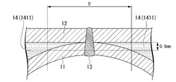
- FIG. 4 is a cross-sectional view perpendicular to the extending direction of the partial flow path of the cooling structure in which the cross-sectional shape of the press-formed member is rectangular;
- FIG. 4 is a plan view of the cooling structure in which the channel communicating portion and the partial channel are perpendicular to each other, viewed from the side of the press-formed member.
- FIG. 4 is a plan view of the cooling structure in which the flow channel communicating portion has a branched structure, viewed from the side of the press-formed member.
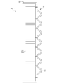
- FIG. 4 is a cross-sectional view perpendicular to the extending direction of the partial flow path of the cooling structure in which the cross-sectional shape of the press-formed member is wavy;
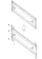
- FIG. 1 is a perspective view of the cooling structure with the beginning and end of the laser weld removed;
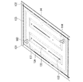
- FIG. 4 is a schematic of the cooling structure with the start and end of the laser weld removed from the flow path perimeter weld.
- FIG. 4 is a schematic of the cooling structure with the start and end of the laser weld removed from the flow path perimeter weld.
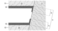
- FIG. 5 is a schematic diagram of a method for measuring the surface coverage of the laser welded portion between the press-formed member and the flow passage top cover. It is a perspective view of a battery unit.
- FIG. 4 is a cross-sectional view of a battery unit using a battery pack as a channel upper lid;
- FIG. 4 is a cross-sectional view of a battery unit in which a battery pack and a channel upper lid are joined;
- 1 is a perspective view of a cooling structure of Example 1.
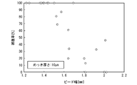
- FIG. 10 is a graph showing the relationship between bead width and coverage in the cooling structure of Example 2 manufactured from a steel plate having a plating thickness of 10 ⁇ m.
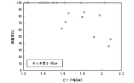
- FIG. 10 is a graph showing the relationship between bead width and coverage in the cooling structure of Example 2 manufactured from a steel plate having a plating thickness of 60 ⁇ m.
- FIG. 11 is a perspective view of a press-formed member before laser welding of the cooling structure of Example 3;
- FIG. 11 is a perspective view of a flow passage top cover before laser welding of the cooling structure of Example 3;
- FIG. 11 is a perspective view of a cooling structure of Example 3;
- the cooling structure 1 includes a press-formed member 11, a flow path upper lid 12, and a laser welded portion 13 joining them.
- a laser weld is a joint made up of a linear bead (that is, weld metal).
- FIG. 1 is a cross-sectional view of this cooling structure 1
- FIG. 2A is a plan view of this cooling structure 1 from the press-formed member 11 side.
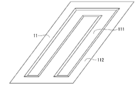
- the press-formed member 11 is a member obtained by press-forming a plated steel sheet, and has a groove portion 111 and bank portions 112 provided around the groove portion 111 .
- the bottom of the press-formed member 11 and its surroundings are grooves 111
- the top of the press-formed member 11 and its surroundings are embankments 112 .
- the flow path upper lid 12 is a member that forms a flat cooling surface, has a flat plate shape, and is superimposed at a position covering the groove portion 111 of the press-formed member 11 .
- the press-formed member 11 and the channel upper lid 12 are joined by a laser welded portion 13 .
- the laser welded portion 13 joins the opposing surfaces of the flow path upper lid 12 and the embankment portion 112 of the press-formed member 11 .
- the channel upper lid 12 and the groove portion 111 form the channel 14 through which the cooling liquid can flow.
- the flow path 14 allows any coolant such as LLC introduced from the coolant inlet 143 to flow to the coolant outlet 144 .
- the passage upper lid 12 which is a cooling surface, and any object that comes into contact with the passage upper lid 12 can be cooled. Note that the flow path shown in FIG.
- the secondA includes a parallel flow path section 141 in which a plurality of partial flow paths 1411 extending along the first direction are arranged in a second direction orthogonal to the first direction, and a parallel flow path section 141 in which these partial flow paths 1411 and a flow passage communicating portion 142 that communicates with the .
- the first direction is, for example, the longitudinal direction or lateral direction of the cooling structure 1 . A specific configuration of the flow path 14 will be described later.
- the shape of the bank portion 112 and the groove portion 111 is not particularly limited.
- the cross sections of the embankment portion 112 and the groove portion 111 are substantially rectangular (trapezoidal).
- the cross-sectional shape of one or both of the bank portion 112 and the groove portion 111 of the press-formed member 11 may be a partial circular shape or a substantially circular arc shape.
- the press-formed member 11 in which the cross-sectional shapes of both the bank portions 112 and the groove portions 111 are partially circular or approximately circular arc-shaped is called a corrugated plate.
- the radius of curvature of the bank portion 112 at the contact portion between the channel top cover 12 and the bank portion 112, that is, the laser welded portion 13, is 15 mm or less, 13 mm or less, or 10 mm or less. There may be.
- the radius of curvature of the bank portion 112 at the contact portion between the channel top cover 12 and the bank portion 112 is parallel to the second direction orthogonal to the first direction, which is the extending direction of the partial channel 1411, and Measured in the cross-section of the partial channel 1411 , which is perpendicular to the surface of the lid 12 .
- a total of three points: the center of the weld metal at the center of the bank portion 112 in the plate thickness direction and two points separated by 1 mm from the center of the weld metal along the second direction. is the radius of curvature of the bank portion 112 at the contact portion between the channel top cover 12 and the bank portion 112 .
- the press-formed member 11 and the flow path upper lid 12 are plated steel sheets having a base material steel sheet and Al plating provided on the surface of the base material steel sheet.
- the structure of the Al-plated steel sheet is not particularly limited, a suitable structure is exemplified as follows.
- the plate thickness of the plated steel sheet that constitutes the press-formed member 11 and the flow passage upper lid 12 may be 0.3 mm or more. By setting the plate thickness to 0.3 mm or more, the press formability and the rigidity of the cooling structure 1 can be further improved.
- the plate thickness of the plated steel sheet forming the press-formed member 11 and the flow passage upper lid 12 may be 0.4 mm or more, 0.6 mm or more, or 0.8 mm or more. On the other hand, the plate thickness of the plated steel sheet forming the press-formed member 11 and the passage upper lid 12 may be 1.2 mm or less.
- the plate thickness of the press-formed member 11 By setting the plate thickness of the press-formed member 11 to 1.2 mm or less, it becomes easier to bring the press-formed member 11 into close contact with the channel upper lid 12, further improving the liquid-tightness of the channel. Further, by setting the plate thickness of the flow path upper cover 12 to 1.2 mm or less, the cooling efficiency of the cooling structure 1 can be further improved.
- the plate thickness of the press-molded member 11 and the channel upper lid 12 may be 1.1 mm or less, 1.0 mm or less, or 0.8 mm or less.
- the plate thicknesses of the press-molded member 11 and the channel upper lid 12 may be different. The thinner the plate thickness, the higher the cooling efficiency.
- the base steel plate of the plated steel plate that constitutes the press-formed member 11 and the flow path upper lid 12 is not particularly limited.
- the base material steel plate of the flow path upper lid 12 may be a high-strength steel plate having a tensile strength of 980 MPa or more.
- the base material steel plate of the press-formed member 11 may be a mild steel plate having a tensile strength of about 270 MPa, such as SPCC.
- the shape of the cooling structure 1 and various forms according to the application can be applied to the base steel plate that constitutes the press-formed member 11 and the flow path upper lid 12 .
- the base material steel plate include IF steel added with Ti, Nb, B, etc., Al-k steel, Cr-added steel, stainless steel, high-tensile steel, low-carbon steel, medium-carbon steel, high-carbon steel, alloy steel, etc. be done.
- the Al-based plating of the plated steel sheet forming the press-formed member 11 and the flow path upper lid 12 is, for example, binary or multi-component plating with an Al content of 70% by mass or more.
- the Al-based plating is a two-component or multi-component plating having an Al content of 70 to 98% by mass and an Si content of 2.0 to 15% by mass.
- the Si content of the Al-based plating may be 3.0% by mass or more, 4.0% by mass or more, or 5.0% by mass or more.
- the Si content of the Al-based plating may be 14% by mass or less, 12% by mass or less, or 10% by mass or less.
- the Si content within the above range, the workability and corrosion resistance of the Al plated steel sheet can be further enhanced.
- a small amount of Fe, Ni, Co, or the like may intervene as an impurity element in the plating layer.
- Mg, Sn, misch metal, Sb, Zn, Cr, W, V, Mo, etc. may be included in the Al-based plating as necessary.
- Al-based plating can be provided by hot-dip plating, hot-dip flux plating, electroplating, or vapor deposition plating by the Zenzimer method or all-radiant method.
- the film thickness of the Al-based plating is also not particularly limited.
- the film thickness of Al-based plating may be 10 ⁇ m or more, 12 ⁇ m or more, 15 ⁇ m or more, or 20 ⁇ m or more.
- the thickness of the Al-based plating may be 60 ⁇ m or less, 50 ⁇ m or less, or 40 ⁇ m or less.
- the corrosion resistance of the inner surface of the cooling structure 1 is enhanced.
- Al is added to the surface of the weld metal of the laser welded portion 13. It is possible to distribute
- the surface of the Al-plated steel sheet is chemically treated.
- chemical conversion treatments may be used for the chemical conversion treatment, but chemical conversion containing one or more selected from the group consisting of Zr-based components, Ti-based components and Si-based components as a main component (for example, 50% by mass or more as mass%) A treated film is preferably formed.
- the chemical conversion coating may contain an organic component.
- the "main component" of the chemical conversion coating means a component that accounts for 50% by mass or more of the chemical conversion coating.
- Examples of chemical conversion coatings are, for example, JP 2008-115442, JP 2013-7108, JP 2004-232040, JP 3302676, JP 4776458, JP 5336002, etc. mentioned. Therefore, the chemical conversion coatings described in these publications can be suitably used as the chemical conversion coating of the present embodiment. Therefore, the outline of the chemical conversion coating is explained here.
- the first example of the chemical conversion treatment film is an example of a film containing Zr-based components as the main component, consisting only of Zr, F, P, C, O, N and H, and having a number average molecular weight of 200 or more. does not contain Among the constituent elements of the chemical conversion coating, the mass ratio Zr/F between Zr and F is 1.0 to 10.0, and the mass ratio Zr/P between Zr and P is 8.5 to 18.0. The components are adjusted so that the Zr content contained therein is 23.0% by mass to 48.0% by mass.
- the source of each component of the chemical conversion treatment film is one or more inorganic acids selected from the group consisting of carbonic acid, phosphoric acid and hydrofluoric acid and/or their ammonium salts, and zirconium-containing complexes other than zirconium hydrofluoric acid. Composed of compounds.
- a second example of the chemical conversion treatment film is an example of a film containing a Zr-based component as a main component, and (A) at least one or more of a titanium compound and a zirconium compound, and (B) two or more of myo-inositol. It contains six combined phosphates and at least one or more selected from alkali metal salts, alkaline earth metal salts and ammonium salts thereof, and (C) silica.
- the mass ratio of (A) in terms of metal (Zr+Ti):(B):(C) is 1:0.2-1.7:0.2-5.
- Titanium compounds include, for example, titanium potassium oxalate, titanyl sulfate, titanium chloride, titanium lactate, titanium isopropoxide, isopropyl titanate, titanium ethoxide, titanium 2-ethyl-1-hexanolate, tetraisopropyl titanate, tetratitanate -n-butyl, titania sol, and the like.
- zirconium compounds include zirconyl nitrate, zirconyl acetate, zirconyl sulfate, zirconyl ammonium carbonate, potassium zirconium carbonate, sodium zirconium carbonate, and zirconium acetate.
- the 2 to 6 linked phosphates of myo-inositol include, for example, myo-inositol diphosphate, myo-inositol triphosphate, myo-inositol tetraphosphate, myo-inositol pentanephosphate, myo-inositol hexane. It is a phosphate ester.
- silica examples include water-dispersible silica compounds.
- Water-dispersible silica compounds include liquid-phase colloidal silica and gas-phase silica.
- the liquid phase colloidal silica is not particularly limited, but includes Snowtex C, Snowtex O, Snowtex N, Snowtex S, Snowtex UP, Snowtex PS-M, Snowtex PS-L, and Snowtex 20. , Snowtex 30, Snowtex 40 (registered trademark) (both manufactured by Nissan Chemical Industries), Adelite AT-20N, Adelite AT-20A, Adelite AT-20Q (both manufactured by Asahi Denka Kogyo), and the like.
- the gas phase silica is not particularly limited, but includes Aerosil 50, Aerosil 130, Aerosil 200, Aerosil 300, Aerosil 380, Aerosil TT600, Aerosil MOX80, Aerosil MOX170 (all manufactured by Nippon Aerosil), and the like.
- a third example of a chemical conversion treatment film is an example of a film containing a Zr-based component as a main component, and is composed of a zirconium compound, a vanadium compound, a silica compound, a phosphoric acid compound, a hydroxyl group, a carbonyl group, and a carboxyl group. It is a composite coating made of an organic compound having at least one functional group among them.
- This chemical conversion coating contains 2 to 1,200 mg/m 2 of zirconium, 0.1 to 300 mg/m 2 of vanadium, and 0.3 to 450 mg/m of phosphate compound in terms of PO 4 3- converted per side of the Al plated steel sheet.
- m 2 contains; Furthermore, the content of chromium or chromium compounds in the chemical conversion treatment film is 0.1 mg/m 2 or less as chromium, and the content of fluorine or fluorine compounds is 0.1 mg/m 2 or less as fluorine.
- zirconium compounds include zirconyl nitrate, zirconyl acetate, zirconyl sulfate, zirconyl ammonium carbonate, potassium zirconium carbonate, sodium zirconium carbonate, and zirconium acetate.
- vanadium compounds include vanadium pentoxide, metavanadic acid, ammonium metavanadate, sodium metavanadate, vanadium oxytrichloride, vanadium trioxide, vanadium dioxide, vanadium oxysulfate, vanadium oxyacetylacetonate, vanadium acetylacetonate, and trichloride. vanadium, phosphovanadomolybdic acid, vanadium sulfate, vanadium dichloride, vanadium oxide and the like.
- silica compounds include water-dispersible silica compounds.
- water-dispersible silica compounds include colloidal silica and gaseous silica.
- colloidal silica include, but are not limited to, Snowtex C, Snowtex O, Snowtex N, Snowtex S, Snowtex UP, Snowtex PS-M, Snowtex PS-L, Snowtex 20, Snowtex 30, Snowtex 40 (all manufactured by Nissan Chemical Industries), Adelight AT-20N, Adelight AT-20A, Adelight AT-20Q (both Asahi Denka Kogyo Co., Ltd.) and the like.
- the gas phase silica is not particularly limited, but includes Aerosil 50, Aerosil 130, Aerosil 200, Aerosil 300, Aerosil 380, Aerosil TT600, Aerosil MOX80, Aerosil MOX170 (all manufactured by Nippon Aerosil), and the like.
- Phosphoric acid compounds include, for example, orthophosphoric acid (phosphoric acid), metaphosphoric acid, pyrophosphoric acid, and salts such as ammonium salts, sodium salts, calcium salts, and potassium salts in which the hydrogen ions of some or all of these substances are replaced. They can be used singly or in combination.
- organic compounds having at least one functional group selected from a hydroxyl group, a carbonyl group, and a carboxyl group include alcohols such as methanol, ethanol, isopropanol, and ethylene glycol, formaldehyde, acetaldehyde, furfural, acetylacetone, ethyl acetoacetate, di Carbonyl compounds such as pivaloylmethane and 3-methylpentanedione; organic acids such as formic acid, acetic acid, propionic acid, tartaric acid, ascorbic acid, gluconic acid, citric acid and malic acid; monosaccharides such as glucose, mannose and galactose; Oligosaccharides such as maltose and sucrose, natural polysaccharides such as starch and cellulose, tannic acid, humic acid, lignosulfonic acid, aromatic compounds such as polyphenol, polyvinyl alcohol, polyethylene glycol, polyacrylic acid, polyacrylamide
- the chemical conversion film may contain, as an additional component, a lubricity imparting component comprising at least one of polyolefin wax and paraffin wax.
- a fourth example of the chemical conversion treatment film is an example of a film containing a Ti-based component as a main component, and is a film in which valve metal oxides or hydroxides and fluorides coexist.
- Valve metals include Ti, V, and the like.
- the tetravalent compound of Ti is preferable because it is a stable compound and can form a film having excellent properties.
- coatings containing a Ti-based component as a main component include coatings in which oxides [TiO 2 ], hydroxides [Ti(OH) 4 ], etc. are combined.
- a fifth example of the chemical conversion treatment film is an example of a film containing Si-based components as a main component, and is a chemical conversion treatment film containing an organosilicon compound (silane coupling agent) as a main component.
- the organosilicon compound comprises a silane coupling agent (A) containing one amino group in the molecule and a silane coupling agent (B) containing one glycidyl group in the molecule at a solid content mass ratio [(A) /(B)] at a ratio of 0.5 to 1.7.
- the organosilicon compound has a functional group (a) represented by the formula —SiR1R2R3 (wherein R1, R2 and R3 each independently represent an alkoxy group or a hydroxyl group, at least one of which represents an alkoxy group) in the molecule. 2 or more, and at least one hydrophilic functional group (b) selected from hydroxyl groups (different from those that can be contained in the functional group (a)) and amino groups. It has a molecular weight of 1,000 to 10,000.
- a sixth example of the chemical conversion treatment film is an example of a film containing Si-based components as a main component, and is a chemical conversion treatment film containing an organosilicon compound (silane coupling agent) as a main component.
- An organosilicon compound has a cyclic siloxane structure in its structure.
- cyclic siloxane bond refers to a cyclic structure having a structure in which Si—O—Si bonds are continuous, composed only of Si and O bonds, and having a Si—O repeating number of 3 to 8.
- the organosilicon compound contains a silane coupling agent (A) containing at least one amino group in the molecule and a silane coupling agent (B) containing at least one glycidyl group in the molecule at a solid content mass ratio of It is obtained by blending [(A)/(B)] at a ratio of 0.5 to 1.7.
- the organosilicon compound (W) thus obtained has the formula —SiR1R2R3 (wherein R1, R2 and R3 each independently represent an alkoxy group or a hydroxyl group, and at least one of R1, R2 and R3 is an alkoxy group is selected from the group consisting of two or more functional groups (a) represented by (representing It preferably contains at least one type of hydrophilic functional group (b) and has an average molecular weight of 1,000 to 10,000.
- Examples of the chemical conversion coating of this embodiment are not limited to the above.
- the method of forming the above-described chemical conversion coating is not particularly limited, and a chemical conversion treatment solution (film treatment solution) corresponding to each of the above compositions may be applied to an Al-plated steel sheet by a known method, and then baked and dried.
- the channel 14 has parallel channel portions 141 in which a plurality of partial channels 1411 extending along the first direction are arranged in a second direction orthogonal to the first direction.
- the first direction is, for example, the longitudinal direction or lateral direction of the cooling structure 1 .
- the width W of the partial channel 1411 As a means for further increasing the contact area between the cooling liquid and the channel upper lid 12, it was considered to widen the width W of the partial channel 1411. However, the greater the width W of the partial flow path 1411, the greater the stress applied to the laser welded portion 13, which may reduce the life of the cooling structure 1. FIG. Also, if the width W of the partial flow path 1411 is too wide, the cooling liquid may not stably flow in the extending direction of the partial flow path 1411, that is, along the first direction, resulting in uneven cooling.
- the interval D between the adjacent partial flow paths 1411 is set to 20 mm or less in part or all of the parallel flow path portion 141 .
- the interval D between the partial channels 1411 may be 18 mm or less, 16 mm or less, or 15 mm or less.
- the interval D of the partial flow path 1411 may be 0.8 mm or more, 1 mm or more, 3 mm or more, 5 mm or more, or 8 mm or more from the viewpoint of preventing poor bonding.
- the interval D between the partial flow paths 1411 is preferably within the range described above in the entire parallel flow path portion 141 .
- the distance D between the partial flow paths 1411 may be greater than 20 mm in a part of the parallel flow path section 141 by, for example, arranging another component such as a screw hole between the partial flow paths 1411 .
- the interval D between the partial flow paths 1411 may be within the range described above in part of the parallel flow path section 141 .
- the width W of the partial flow paths 1411 is not particularly limited. From the viewpoint of further increasing the contact area between the channel forming portion and the channel upper lid 12, the width W of the partial channel 1411 may be 6 mm or more, 8 mm or more, or 10 mm or more. On the other hand, from the viewpoint of further increasing the bonding strength between the press-formed member 11 and the flow passage upper lid 12 and further improving the cooling uniformity, the width W of the partial flow passage 1411 is set to 60 mm or less, 30 mm or less, 25 mm or less, or 20 mm. The following may be used.
- the height of the partial flow path 1411 is also not particularly limited, but it may be 1 mm or more, for example, in order to further improve the cooling efficiency. On the other hand, in order to reduce the weight of the cooling structure 1, the partial flow path 1411 may have a height of 10 mm or less.
- the shape of the partial channel 1411 described above may be applied to the partial channel that constitutes the channel communication portion 142 .
- the flow path 14 and the partial flow path 1411 included therein mean a space through which the cooling liquid can easily flow and exhibit a substantial cooling effect. Therefore, as shown in FIG. 4, the flow path 14 and the partial flow path 1411 are the space between the flow path top lid 12 and the press-molded member 11 and have a thickness along the direction perpendicular to the flow path top lid 12. is defined as a space with a width of 0.5 mm or more.
- the interval D between the partial flow paths 1411 is the interval between the spaces defined above.
- the interval D of the partial channel 1411 is the width of the region where the laser welded portion 13, the channel upper lid 12 and the press-formed member 11 are in contact, and the distance between the channel upper lid 12 and the press-formed member 11. It is the total length of the width of the area where the gap is less than 0.5 mm.
- the width W of the partial flow path 1411 is the width of the space defined above. That is, the width W of the partial channel 1411 is the width of the space with a thickness of 0.5 mm or more along the direction perpendicular to the channel upper lid 12 .
- the interval D of the partial flow path 1411 and the width W of the partial flow path are values measured along the second direction perpendicular to the first direction, which is the extending direction of the partial flow path 1141 .
- the joints for forming the flow paths 14 are laser welded portions 13 .
- Laser welding can reduce the bead width. Therefore, this joining means is effective for narrowing the interval D between the partial flow paths 1411 .
- laser welding forms a linear bead, so that the fluid tightness of the flow path 14 can be improved more than a point joining method such as spot welding.
- the configuration of the laser welded portion 13 is not particularly limited, and various configurations can be adopted according to the shape of the flow path 14 . Preferred aspects of the laser welded portion 13 are described below.
- the bead width on the laser irradiation side that is, the bead width of the surface of the laser welded portion 13 in the flow path upper lid 12 and the surface bead width of the laser welded portion 13 in the press-formed member 11, whichever is larger, is set to 0.8 to 1.0. 5 mm may be used.
- the bead width By setting the bead width to 0.8 mm or more, the liquid tightness of the flow path 14 can be further enhanced.
- the bead width to 1.5 mm or less, evaporation of the plating in the vicinity of the bead can be prevented, and the corrosion resistance of the cooling structure 1 can be further enhanced.
- the laser welded portion 13 may be formed so as to satisfy all of the following three requirements.
- (1) The width of the thicker one of the beads of the laser welded portion 13 is set to 0.8 to 1.5 mm as described above.
- (3) The distance between the press-formed member 11 and the flow passage upper lid 12 in the vicinity of the laser welded portion 13 is 0.3 mm or less.
- the base material steel plate and Al-based plating are molten and solidified by laser welding, so there is no Al plating on the surface of the weld metal that constitutes the laser-welded portion.
- the inventors of the present invention welded Al-plated steel sheets under various conditions and investigated the weld metals obtained thereby, the welds obtained by laser welding satisfying all of the above requirements (1) to (3)
- the surface of the metal was covered with Al-based plating between the press-formed member 11 and the channel upper lid 12 .
- Al-based plating around the laser welded portion melts due to the heat of the laser welding and moves to the surface of the weld metal of the laser welded portion 13 .
- the bead width of the requirement (1) has a strong correlation with the amount of heat input during laser welding. If the bead width is too large, the heat input during laser welding is too large, and the Al-based coating disappears over a wide area around the weld metal, and the molten Al-based coating does not move to the surface of the weld metal. On the other hand, if the bead width is too small, there is a possibility that the flow path upper lid 12 and the press-formed member 11 are not sufficiently joined.
- the plating film thickness of the above requirement (2) is too small, the molten Al-based plating will be insufficient and the molten Al-based plating will not move to the surface of the weld metal.
- the gap between the plated steel sheets of the requirement (3) is too large, the weld metal is too large, and it is considered that the weld metal is not covered by the hot-dip Al-based plating.
- the plate interval of the plated steel sheet in the above requirement (3) is the interval between the press-formed member and the upper lid of the flow path, which is measured in the vicinity of the laser welded portion 13 .
- the vicinity of the laser welded portion 13 is a region within 0.1 mm from the weld metal included in the laser welded portion 13 .
- the distance between the press-formed member and the upper lid of the flow path is substantially constant, so the distance can be measured at any point within this area.
- the plated steel sheet spacing changes little, and the value measured within this range can be used as the plated steel sheet spacing.
- the distance between the press-formed member 11 and the flow path upper lid 12 in the vicinity of the laser welded portion 13 is preferably 0.2 mm or less, 0.1 mm or less, or 0.05 mm or less.
- the laser welded portion 13 is composed of a starting end portion 131, a terminal end portion 132, and an intermediate portion 133 therebetween.
- a starting end portion 131 of the laser welded portion 13 is a portion corresponding to a portion where laser welding is started, and an end portion 132 of the laser welded portion 13 is a portion corresponding to a portion where laser welding is finished.
- the intermediate portion 133 has fewer weld defects than the starting portion 131 and the terminal portion 132, and therefore tends to be more excellent in corrosion resistance and liquid tightness. Therefore, it is preferable that the channel 14 is formed using the intermediate portion 133 of the laser welded portion 13 and is separated from the starting end portion 131 and the terminal end portion 132 .
- the laser welding is performed so that the intermediate portion 133 of the laser welded portion 13 is arranged between the start end portion 131 and the end portion 132 of the laser welded portion 13 and the flow path 14. is preferably performed. As a result, the starting end portion 131 and the terminal end portion 132 can be prevented from being exposed to the coolant. Moreover, as illustrated in FIG.
- the starting end portion 131 and the terminal end portion 132 of the laser welded portion 13 are removed from the cooling structure 1 .
- a tab plate T is provided on the flow path upper lid 12 or the press-formed member 11 before being laser-welded, laser welding is performed so that the tab plate T has a starting end portion 131 and an end portion 132, and then the tab plate T is formed. can be obtained by cutting and removing the cooling structure 1 that does not include the starting end portion 131 and the terminal end portion 132 of the laser welded portion 13 .
- a configuration in which the leading end portion 131 and the terminal end portion 132 are excluded may be applied only to locations where liquid leakage is a concern.
- the cooling structure 1 shown in FIGS. 6A and 6B of the laser-welded portion 13, the portion provided along the outer edge of the press-formed member 11 and the flow passage upper lid 12 (dark colored ), the cooling liquid leaks to the outside of the cooling structure 1 when the flow path upper cover 12 is separated from the press-formed member 11 .
- the cooling structure 1 illustrated in FIG. 6A is obtained by manufacturing the passage outer edge welded portion 13A using only the intermediate portion 133 of the laser welded portion 13, as in FIG. 5A. In this case, the beginning and end portions are excluded from the channel outer edge weld 13A but remain in the cooling structure 1.
- FIG. 1 On the other hand, in the cooling structure 1 exemplified in FIG.
- the tab plate T is provided on the flow path upper lid 12 or the press-formed member 11 before being laser-welded, and the tab plate T has a starting end portion 131 and a terminal end portion 131, as in FIG. 5B. It is obtained by performing laser welding so that the portion 132 is formed, and then removing the tab plate T by cutting. In this case, the starting end and the terminal end generated when forming the flow path outer edge welded portion 13A do not remain in the cooling structure 1 .
- the bead height of the laser welded portion 13 in the flow path upper lid 12 may be 0.3 mm or less.
- the gap between the flow path upper lid 12 and the object to be cooled (for example, a battery pack or battery cell) can be reduced to further improve the cooling efficiency.
- the bead height of the laser welded portion 13 may be reduced, for example, through control of the laser welding conditions. Also, the bead height may be reduced by grinding the bead after the laser welding is finished.
- the channel 14 may be further provided with a channel communicating portion 142 that communicates the plurality of partial channels 1411 .
- a coolant inlet 143 and a coolant outlet 144 for introducing coolant into the channel may be further provided in the channel 14 .
- the channel 14 forms one space.
- the cooling structure 1 may be provided with one coolant inlet 143 and one coolant outlet 144 .
- the flow path communicating portion 142 may not be provided in the cooling structure 1 .
- a cooling liquid inlet 143 and a cooling liquid outlet 144 may be provided for each of the plurality of partial flow paths 1411 .
- each of the two channel communicating portions 142 is a single straight channel, and the channel communicating portion 142 communicates with all the partial channels 1411 so as to be perpendicular to each other.
- the shape of the channel communicating portion 142 and the arrangement of the channel communicating portion 142 and the partial channel 1411 are not limited to this.
- the angle formed by the channel communicating portion 142 and the partial channel 1141 is not limited to 90°, and can be appropriately selected according to the application of the cooling structure 1 .
- the flow path communication part 142 may have a branch structure. As shown in FIG.
- each of the two flow path communicating portions 142 branches into a fan shape starting from the cooling liquid inlet 143 or the cooling liquid outlet 144, and communicates with each partial flow path 1411 at various angles at the branch destination. may be Note that the laser welded portion 13 is omitted in FIG. 2B.
- 30% or more of the surface of the laser-welded portion 13 may be covered with Al-based plating between the press-formed member 11 and the flow passage upper lid 12 .
- the coolant corrosion resistance of the laser welded portion 13 is improved, and the coolant corrosion resistance of the cooling structure 1 is further enhanced.
- any one of the plurality of partial flow paths 1411 included in the cooling structure 1 is cut perpendicularly to its extending direction, that is, the first direction.
- the points to be cut are three points in total: the midpoint of both ends of the partial flow channel 1411 and two midpoints between this midpoint and the end of the partial flow channel 1411 .
- Both ends of the partial channel 1411 are places where the partial channel 1411 and the channel communicating portion 142 intersect when the above-described channel communicating portion 142 is included in the cooling structure 1, and the channel communicating portion 142 is used for cooling.
- it is the location where the coolant inlet 143 and the coolant outlet 144 are provided.
- the plan view shape of the press-formed member 11 and the flow path upper cover 12 that constitutes the cooling surface of the cooling structure 1 is not particularly limited.
- the shape of the upper lid 12 in plan view is preferably rectangular.
- the size of the flow path upper lid 12 in plan view is preferably 1000 mm to 2300 mm in the longitudinal direction and 200 mm to 1500 mm in the lateral direction.
- the size of the press-formed member 11 in plan view is also preferably 1000 mm to 2300 mm in the longitudinal direction and 200 mm to 1500 mm in the lateral direction.
- the longitudinal dimension of the flow path upper lid 12 in plan view may be 1200 mm or more, 1400 mm or more, or 1600 mm or more.
- the longitudinal dimension of the flow path upper lid 12 in plan view may be 2200 mm or less, 2000 mm or less, or 1800 mm or less.
- the width of the flow path upper lid 12 in a plan view may be 250 mm or more, 500 mm or more, or 700 mm or more.
- the width of the flow path upper lid 12 in a plan view may be 1400 mm or less, 1300 mm or less, or 1200 mm or less.
- the longitudinal dimension of the press-formed member 11 in plan view may be 1200 mm or more, 1400 mm or more, or 1600 mm or more.
- the longitudinal dimension of the press-formed member 11 in plan view may be 2200 mm or less, 2000 mm or less, or 1800 mm or less.
- the size of the press-formed member 11 in the lateral direction in plan view may be 250 mm or more, 500 mm or more, or 700 mm or more.
- the size of the press-formed member 11 in the lateral direction in plan view may be 1400 mm or less, 1300 mm or less, or 1200 mm or less.
- the press-formed member 11 and the flow path upper lid 12 are made of Al-plated steel sheets, thereby improving the outer surface corrosion resistance and the coolant corrosion resistance. As a result, waterway corrosion can be suppressed, and the generation of contamination that causes a decrease in thermal conductivity and clogging can be suppressed. Further, in the cooling structure according to the first embodiment, by laser-welding the press-formed member 11 and the flow path upper lid 12, the interval D between the partial flow paths 1411 in the parallel flow path portion 141 is set to 20 mm or less, and the cooling liquid and The cooling efficiency can be improved by increasing the contact area with the flow path upper lid 12 . In addition, in the cooling structure according to the first embodiment, by laser-welding the press-formed member 11 and the channel upper lid 12, the liquid-tightness of the channel 14 can be enhanced.
- the battery unit 2 includes battery cells 21, a battery pack 22 housing the battery cells 21, and the cooling structure 1 according to the first embodiment. .
- the battery pack 22 can be used as the flow path upper lid 12 of the cooling structure 1, as shown in FIG. 8B.
- the bank portion 112 of the press-formed member 11 and the battery pack 22 can be laser-welded.
- the battery unit 2 may be manufactured by joining the flow path upper lid 12 and the battery pack 22 together.
- a gap filler 23 may be arranged between the upper lid 12 and the battery pack 22 . It may be difficult to join the battery pack 22 and the flow path upper lid 12 of the cooling structure 1 without gaps due to some cause (error in dimensional accuracy, formation of complex irregularities on the battery pack 22, etc.). In such cases, gap filler 23 can be used.
- the gap filler 23 is generally a resin containing a highly thermally conductive pigment. The heat exchange efficiency can be improved by inserting the gap filler 23 between different substances.
- the thermal conductivity of the gap filler 23 is preferably 3.5 W/m or more.
- An example of the gap filler 23 is "SDP-3540-A" manufactured by Shin-Etsu Silicone Co., Ltd.
- the thickness of the gap filler is preferably 0.1 mm to 8.0 mm, more preferably 0.5 mm to 3.0 mm.
- the configuration of the battery pack 22 is not particularly limited.
- the battery pack 22 may have a substantially rectangular shape, and the cooling structure 1 may be arranged on the bottom surface thereof, or the bottom surface may serve as the upper lid 12 of the cooling structure 1 .
- the steel sheet forming the battery pack 22 is preferably an Al-plated steel sheet or a Zn-plated steel sheet.
- the part where the cooling structure 1 is attached in the battery pack 22 for example, the bottom part is provided with coolant corrosion resistance. is not required.
- the thickness of the Al-plated steel sheet forming the bottom surface of the battery pack 22 is not particularly limited, but is preferably 0.2 to 1.2 mm or 0.3 to 1.2 mm, and preferably 0.4 to 0.4 mm. More preferably 0.6 mm.
- the bottom portion of the battery pack 22 can be formed thin while maintaining the strength of the bottom portion. Therefore, the distance between the coolant and the internal structure of the battery pack 22 can be reduced, so that the cooling efficiency of the battery pack 22 can be improved, and the cooling response of the battery pack 22 can be improved.
- a method for manufacturing a cooling structure according to the third embodiment includes a step S1 of press-forming a plated steel sheet to obtain a press-formed member 11, and a step S2 of laser-welding the press-formed member and the channel upper lid. Details of these steps are described below. According to this manufacturing method, the cooling structure according to the first embodiment can be suitably manufactured. However, the following description does not limit the manufacturing method of the cooling structure according to the first embodiment.
- the cooling structure manufacturing method In the cooling structure manufacturing method according to the present embodiment, first, a plated steel sheet is press-formed. As a result, the press-formed member 11 having the groove portion 111 and the bank portion 112 provided around the groove portion 111 is obtained. A plated steel sheet to be press-formed has Al-based plating. A preferred form of the plated steel sheet is as described above.
- the flow path 14 has parallel flow path portions 141 in which a plurality of partial flow paths 1411 extending along the first direction are arranged in a second direction orthogonal to the first direction. In the parallel channel portion 141, the interval D between adjacent partial channels 1411 is set to 20 mm or less. In order to achieve such a shape of the flow path 14, it is necessary to form the groove 111 in press molding.
- the laser welding conditions are not particularly limited, and suitable conditions can be appropriately adopted according to the thickness of the plated steel sheet.
- An example of particularly suitable laser welding conditions is that the film thickness of the Al-based plating is 10.0 ⁇ m or more, and the distance between the press-formed member 11 and the flow passage upper lid 12 in the vicinity of the laser welded portion is 0.3 mm or less.
- the Al-based plating around the welded portion is melted and moved to the surface of the laser welded portion 13, whereby a part of the surface of the laser welded portion 13 or All can be covered with Al-based plating.
- the beam diameter is 0.4 to 0.6 mm and the heat input per unit welding length is 30 to 60 kJ/m.
- a press-formed member was produced by press-forming an Al-based plated steel sheet.
- a cooling structure was manufactured by laser-welding this press-formed member and a channel upper cover made of a flat plate of an Al-plated steel sheet.
- Table 1 shows channel widths and channel intervals of a plurality of partial channels extending in parallel. The manufacturing conditions not included in Table 1 were as follows. No flow passage connecting portion for connecting the partial flow passages was created.
- ⁇ Type of plated steel plate Aluminized mild steel plate with a thickness of 0.5 mm (Al-9% Si plated steel plate is used)
- ⁇ Laser welding machine Fiber laser welding machine ⁇ Heat input conditions during laser welding: 45000 J/m ⁇ Shape of the cooling structure of the example: described in FIG. 9 ⁇ Partial channel length: 200 mm ⁇ Partial channel height: 10 mm
- FIG. 9 is a schematic diagram of a portion of the manufactured cooling structure. For convenience, only two sub-channels are shown in FIG. 9, but in practice, the cooling structure was provided with a number of sub-channels sufficient to cover a battery with a width of 120 mm. In all examples shown in the table, the cooling structure could be assembled by laser welding.
- Table 1 also shows the evaluation results of the cooling structure created as described above. Evaluation criteria were as described below. Regarding the flow channel width W of the partial flow channel, those having a width W of 20 mm or less were ranked as "S”, those having a width of more than 20 mm and less than or equal to 30 mm were ranked as "A”, and those having more than 30 mm were ranked as "B”. This is because the smaller the flow path width W, the more stable the flow of the coolant and the more improved the cooling efficiency. "D/2" is a value obtained by dividing the interval D between the plurality of partial flow paths by 2. This value is the maximum distance in the width direction of the channel at which the partial channels are not in direct contact with each other, and is preferably as small as possible.
- the width of the thicker one of the bead of the laser-welded portion in the flow passage upper lid and the bead of the laser-welded portion in the press-formed member (hereinafter simply referred to as "bead width") is within the range of 1.2 mm to 2.2 mm.
- Various cooling structures were manufactured by changing the heat input conditions within the range of 30 to 120 kJ/m.
- the distance between the upper cover of the flow passage and the press-formed member in the vicinity of the laser welded portion was within the range of 0 to 0.2 mm.
- the film thickness of plating was 10 ⁇ m or 60 ⁇ m. In laser welding, plated steel sheets with the same film thickness were combined.
- the cross section of the laser welded portion was observed to confirm whether or not the surface of the laser welded portion was covered with Al-based plating between the press-formed member and the front cover. Also, the ratio of the area of the Al-based plating covering the laser welded portion to the surface area of the laser welded portion (hereinafter referred to as "coverage ratio") was measured. The measurement method of the coverage was as described above with reference to FIG.
- Fig. 10A shows the relationship between the bead width and the coverage in a cooling structure manufactured from a steel plate with a plating film thickness of 10 ⁇ m.
- FIG. 10B shows the relationship between the bead width and the coverage in the cooling structure manufactured from the steel plate with a plating thickness of 60 ⁇ m.
- the bead width was 1.5 mm or less, the entire surface of the laser welded portion was coated with Al-based plating. These examples are believed to have high internal corrosion resistance.
- the coverage tended to decrease as the bead width increased.
- Example 3 Corrosion resistance evaluation Various cooling structures were manufactured by applying the welding method, partial channel spacing, distance between steel plates, plating film thickness, and laser welding heat input shown in Table 2.
- the distance between the steel plates is the distance between the upper cover of the flow channel and the press-formed member at the location where laser welding is performed.
- spot welding using a general welding electrode with an electrode diameter of ⁇ 16 mm was used instead of laser welding.
- the description of the heat input is omitted.
- the shapes of the press-formed member and the flow channel upper lid before welding were as shown in FIGS. 11A and 11B, and the shape of the flow channel was as shown in FIG.
- the cross-sectional shape of the partial flow channel was made to be the waveform shown in FIG. 3, but otherwise the same shape as the other examples was adopted.
- the channel shape in plan view is U-shaped, and the two channels extending in the vertical direction correspond to the partial channels.
- the channel width was 20 mm in all cooling structures.
- the bead widths of the fabricated cooling structures were measured and listed in Table 3.
- the bead width shown in Table 3 is the width of the larger one of the bead of the laser-welded portion of the flow passage upper cover and the bead of the laser-welded portion of the press-formed member.
- a pump was also connected to the cooling structure to circulate a long-life coolant (LLC).
- LLC long-life coolant
- a filter was connected between the pump and the cooling structure to prevent any corrosion products from entering the pump.
- the LLC was circulated for 100 hours under the condition that the pressure in the flow channel was 1.5 atm and the LLC temperature was 50°C.
- the inner surface plating state, bead width, and inner surface corrosion resistance were evaluated by the following methods, and the results are shown in Table 3.
- the condition of the inner surface plating was evaluated by dismantling the channel after fabricating the channel under the same conditions and observing the cross section of the welded portion.
- Example 1 spot welding could not be performed. This is because the electrode of ⁇ 16 mm could not be brought into contact with the intended welding location when the passage interval was 5 mm.
- Cooling structure Press-formed member 111 Groove 112 Embankment 12 Channel upper lid 13 Laser welded part 13A Channel outer edge welded part 131 Starting end 132 Terminating part 133 Intermediate part 14 Channel 141 Parallel channel part 1411 Partial channel 142 Channel Communicating portion 143 Coolant inlet 144 Coolant outlet 15 Base material steel plate 16 Al-based plating 2 Battery unit 21 Battery cell 22 Battery pack 23 Gap filler R Circle T indicating the radius of curvature of the bank Tab plate L Laser D Flow path interval W Width of channel
Abstract
Description
本願は、2021年5月20日に、日本に出願された特願2021-085188号に基づき優先権を主張し、その内容をここに援用する。
特許文献3の技術では、アルミ系めっき鋼板をろう付けすることにより冷却器を製造している。しかし、特許文献3の技術は専ら小型の装置に適用することが想定されており、多様なサイズの冷却器に対応することは難しい。また、特許文献3においては外装部材の変形を防止することが課題とされており、外装部材の接合手段を変更することは難しい。
(2)上記(1)に記載の冷却構造では、前記並列流路部において、隣り合う前記部分流路同士の間隔が0.8~15mmであってもよい。
(3)上記(1)又は(2)に記載の冷却構造では、前記部分流路の幅が6~60mmであってもよい。
(4)上記(1)又は(2)に記載の冷却構造では、前記部分流路の幅が6~20mmであってもよい。
(5)上記(1)~(4)のいずれか一項に記載の冷却構造では、前記Al系めっきにSiが含まれていてもよい。
(6)上記(5)に記載の冷却構造では、前記Al系めっきのSi含有量が2.0~15質量%であってもよい。
(7)上記(1)~(6)のいずれか一項に記載の冷却構造では、前記めっき鋼板が、表面に、Zr系成分、Ti系成分又はSi系成分を50質量%以上の割合で含む化成処理皮膜を有してもよい。
(8)上記(1)~(7)のいずれか一項に記載の冷却構造では、前記堤部の断面形状が略円弧であり、前記流路上蓋と、前記堤部との接触部における、前記堤部の曲率半径が15mm以下であってもよい。
(9)上記(1)~(8)のいずれか一項に記載の冷却構造では、前記Al系めっきの膜厚が10.0μm以上であり、前記レーザ溶接部の近傍における、前記プレス成形部材と前記流路上蓋との間隔が0.3mm以下であり、前記流路上蓋における前記レーザ溶接部の表面のビード幅、及び前記プレス成形部材における前記レーザ溶接部の表面のビード幅のうち太い方が、0.8~1.5mmであってもよい。
(10)上記(1)~(9)のいずれか一項に記載の冷却構造では、前記プレス成形部材及び前記流路上蓋を構成する前記めっき鋼板の板厚が0.3~1.2mmであってもよい。
(11)上記(1)~(10)のいずれか一項に記載の冷却構造では、前記レーザ溶接部が、全ての前記流路を包囲する流路外縁溶接部を有し、前記レーザ溶接部の始端及び終端が、前記流路外縁溶接部から除外されていてもよい。
(12)上記(1)~(11)のいずれか一項に記載の冷却構造では、前記冷却構造から、前記レーザ溶接部の始端部及び終端部が除かれていてもよい。
(13)上記(1)~(12)のいずれか一項に記載の冷却構造では、前記プレス成形部材及び前記流路上蓋の間において、前記レーザ溶接部の表面の一部又は全部が前記Al系めっきによって覆われていてもよい。
(14)上記(1)~(13)のいずれか一項に記載の冷却構造では、前記プレス成形部材及び前記流路上蓋の間において、前記レーザ溶接部の表面の30%以上が前記Al系めっきによって覆われていてもよい。
(15)上記(1)~(14)のいずれか一項に記載の冷却構造では、前記流路上蓋における、前記レーザ溶接部のビード高さが0.3mm以下であってもよい。
(17)本発明の別の態様に係るバッテリーユニットは、電池セルと、前記電池セルが収納されたバッテリーパックと、上記(1)~(15)のいずれか一項に記載の冷却構造とを備え、前記冷却構造の前記流路上蓋が前記バッテリーパックである。
(19)上記(18)に記載の冷却構造の製造方法では、前記Al系めっきの膜厚が10.0μm以上であり、前記レーザ溶接において、ビーム径を0.2~0.8mmとし、単位溶接長当たりの入熱を30~120kJ/mとし、かつ、前記レーザ溶接部の近傍における、前記プレス成形部材と前記流路上蓋との間隔を0.3mm以下としてもよい。
まず、本発明の第一実施形態に係る冷却構造について説明する。本実施形態に係る冷却構造1は、図1及び図2Aに示されるように、プレス成形部材11と、流路上蓋12と、これらを接合するレーザ溶接部13とを有する。レーザ溶接部とは、線状のビード(即ち溶接金属)から構成される接合部のことである。図1は、この冷却構造1の断面図であり、図2Aは、この冷却構造1をプレス成形部材11側から平面視した図である。
プレス成形部材11は、めっき鋼板をプレス成形することによって得られた部材であり、溝部111、及び、溝部111の周囲に設けられた堤部112を有する。図1において、プレス成形部材11の底部及びその周辺が溝部111であり、プレス成形部材11の頂部及びその周辺が堤部112である。流路上蓋12は、平坦な冷却面を構成する部材であり、平板形状を有し、プレス成形部材11の溝部111を覆う位置に重ねられている。
プレス成形部材11と流路上蓋12は、レーザ溶接部13によって接合されている。具体的には、レーザ溶接部13は、流路上蓋12とプレス成形部材11の堤部112との互いに対向する面同士を接合する。これにより、流路上蓋12及び溝部111は、冷却液が流通可能な流路14を形成する。図2Aの破線で示されるように、流路14には、冷却液入口143から導入されたLLC等の任意の冷却液を、冷却液出口144へと流通させることができる。これにより、冷却面である流路上蓋12、及び流路上蓋12と接触する任意の物体を冷却することができる。なお、図2Aに示される流路は、第1方向に沿って延びる複数の部分流路1411が、第1方向と直交する第2方向に並ぶ並列流路部141と、これらの部分流路1411を連通する流路連通部142とを有する。第1方向とは、例えば、冷却構造1の長手方向又は短手方向である。流路14の具体的な構成については後述する。
プレス成形部材11及び流路上蓋12は、母材鋼板と、母材鋼板の表面に設けられたAlめっきとを有するめっき鋼板である。Alめっき鋼板の構成は特に限定されないが、好適な構成を例示すると以下の通りである。
プレス成形部材11及び流路上蓋12を構成するめっき鋼板の母材鋼板は、特に限定されない。例えば冷却構造1の剛性を一層高めるために、流路上蓋12の母材鋼板を、引張強さ980MPa以上の高強度鋼板としてもよい。一方、プレス成形性を一層高めるために、プレス成形部材11の母材鋼板を引張強さ約270MPaの軟鋼板、例えばSPCCとしてもよい。冷却構造1の形状、及び用途に応じた種々の形態を、プレス成形部材11及び流路上蓋12を構成する母材鋼板に適用することができる。母材鋼板の例として、Ti、Nb、B等を添加したIF鋼、Al-k鋼、Cr添加鋼、ステンレス鋼、ハイテン、低炭素鋼、中炭素鋼、高炭素鋼、合金鋼等が挙げられる。
プレス成形部材11、及び流路上蓋12を構成するめっき鋼板のAl系めっきは、例えばAl含有量が70質量%以上である2成分系又は多成分系のめっきである。好ましくは、Al系めっきは、Al含有量が70~98質量%であり、Si含有量が2.0~15質量%の2成分系又は多成分系のめっきである。Al系めっきのSi含有量は、3.0質量%以上、4.0質量%以上、又は5.0質量%以上であってもよい。Al系めっきのSi含有量は、14質量%以下、12質量%以下、又は10質量%以下であってもよい。Si含有量を上記範囲内とすることで、Al系めっき鋼板の加工性及び耐食性を一層高めることができる。めっき層中の不純物元素として、微量のFe、Ni、Co等が介在してもよい。また、必要に応じ、Mg、Sn、ミッシュメタル、Sb、Zn、Cr、W、V、Mo、等がAl系めっきに含まれてもよい。
Al系めっき鋼板等の外面耐食性及び冷却液耐食性をさらに高めるために、Al系めっき鋼板等の表面には、化成処理が施されていると好適である。化成処理は一般に公知の化成処理を用いても良いがZr系成分、Ti系成分及びSi系成分からなる群から選択される一種以上を主成分(例えば質量%として50質量%以上)として含む化成処理皮膜が形成されていることが好ましい。Zr系成分、Ti系成分及びSi系成分のうち2種以上が化成処理皮膜に含まれる場合は、これら成分の合計含有量が50質量%以上であればよい。また、化成処理皮膜には有機成分が含まれていてもよい。以下、化成処理皮膜の「主成分」とは、化成処理皮膜に占める割合が50質量%以上である成分を意味する。
次に、本実施形態に係る冷却構造1の流路14の構成について説明する。
冷却構造1の冷却効率を高めるためには、冷却液と、流路上蓋12との間の接触面積を大きくすること、即ち、流路上蓋12における流路14に面している領域の面積を大きくすることが好ましい。このため、流路14は、第1方向に沿って延びる複数の部分流路1411が第1方向と直交する第2方向に並ぶ、並列流路部141を有する。第1方向とは、例えば、冷却構造1の長手方向又は短手方向である。部分流路1411を平行に複数配置した並列流路部141を設けることにより、冷却液と流路上蓋12との接触面積を増大させることができる。しかし、一層優れた冷却効率を確保するために、本発明者らはさらなる検討を重ねた。
部分流路1411の間隔Dを上述の範囲内とするために、本実施形態に係る冷却構造1では、流路14を形成するための接合部をレーザ溶接部13とする。レーザ溶接は、ビード幅を細くすることができる。従って、部分流路1411の間隔Dを狭めるために有効な接合手段である。また、レーザ溶接は線状のビードを形成するので、スポット溶接のような点接合手段よりも、流路14の液密性を高めることができる。
(1)レーザ溶接部13のビードのうち太い方の幅を、上述のように0.8~1.5mmとすること
(2)プレス成形部材11及び流路上蓋12を構成するめっき鋼板が有するAl系めっきの膜厚を、上述のように10.0μm以上とすること
(3)レーザ溶接部13の近傍における、プレス成形部材11と流路上蓋12との間隔を0.3mm以下とすること
上記要件(1)~(3)を全て満たすようにレーザ溶接部13を形成すると、プレス成形部材11及び流路上蓋12の間において、レーザ溶接部13の表面の一部又は全部が、Al系めっきによって被覆される。これにより、冷却構造1の冷却液耐食性が一層向上する。
また、図5Bに例示されるように、冷却構造1から、レーザ溶接部13の始端部131及び終端部132が除かれていることが一層好ましい。例えば、レーザ溶接される前の流路上蓋12又はプレス成形部材11にタブ板Tを設け、タブ板Tに始端部131及び終端部132が形成されるようにレーザ溶接を行い、その後タブ板Tを切断除去することにより、レーザ溶接部13の始端部131及び終端部132を含まない冷却構造1を得ることができる。
なお、図6Aに例示される冷却構造1は、図5Aと同様に、レーザ溶接部13の中間部133のみを用いて流路外縁溶接部13Aを製造することにより得られたものである。この場合、始端部及び終端部は流路外縁溶接部13Aからは排除されているが、冷却構造1には残される。一方、図6Bに例示される冷却構造1は、図5Bと同様に、レーザ溶接される前の流路上蓋12又はプレス成形部材11にタブ板Tを設け、タブ板Tに始端部131及び終端部132が形成されるようにレーザ溶接を行い、その後タブ板Tを切断除去することにより得られたものである。この場合、流路外縁溶接部13Aを形成する際に生じた始端部及び終端部は、冷却構造1に残らない。また、流路上蓋12及びプレス成形部材11に当たらない箇所からレーザの照射を開始した後、レーザ溶接を行い、走り抜けるように流路上蓋12及びプレス成形部材11に当たらない箇所までレーザを照射し、その後にレーザ照射を停止することでも、流路外縁溶接部13Aの形成における始端部及び終端部が冷却構造1に残らない。
図2Aに示されるように、複数の部分流路1411を連通する流路連通部142が、流路14にさらに設けられてもよい。また、流路に冷却液を導入するための冷却液入口143、及び冷却液出口144が、流路14にさらに設けられてもよい。流路14が流路連通部142を有する場合、流路14は1つの空間をなすこととなる。この場合、冷却構造1には、冷却液入口143及び冷却液出口144が1つずつ設けられれば良い。一方、流路連通部142が冷却構造1に設けられなくてもよい。この場合、複数の部分流路1411それぞれに、冷却液入口143及び冷却液出口144を設ければよい。複数の部分流路1411の一部のみが流路連通部142によって連通され、流路14が2以上の空間をなしてもよい。
なお図2A等においては、2つの流路連通部142それぞれが一本の真っ直ぐな流路であり、流路連通部142が全ての部分流路1411に直交するように連通しているが、流路連通部142の形状、及び、流路連通部142と部分流路1411の配置はこれに限定されない。例えば、流路連通部142と部分流路1141とがなす角度は90°に限定されず、冷却構造1の用途に応じて適宜選択することができる。また、流路連通部142が分岐構造を有していてもよい。図2Bに示されるように、2つの流路連通部142それぞれが冷却液入口143又は冷却液出口144を起点に扇状に分岐し、その分岐先において各部分流路1411と種々の角度をもって連通していてもよい。なお、図2Bにおいて、レーザ溶接部13は省略されている。
まず、冷却構造1に含まれる複数の部分流路1411のうち任意の1本を、その延在方向、即ち第1方向に垂直に切断する。切断する箇所は、部分流路1411の両端の中間点、及びこの中間点と部分流路1411の端部との中間点2点の合計3点である。部分流路1411の両端とは、上述の流路連通部142が冷却構造1に含まれるときは、部分流路1411と流路連通部142とが交わる箇所であり、流路連通部142が冷却構造1に含まれないときは、冷却液入口143及び冷却液出口144が設けられた箇所である。
次に、上述の3か所の切断面におけるレーザ溶接部13の顕微鏡写真を撮影する。
そして、図7に示されるように、断面におけるレーザ溶接部13を構成する溶接金属の表面の長さaを分母とし、この溶接金属の表面に付着したAl系めっきの、溶接金属表面に沿った長さbの合計を分子として、各断面における被覆率を測定する。さらに、3つの断面における被覆率の平均値を算出し、これを、Al系めっきによるレーザ溶接部13の被覆率とみなす。
レーザ溶接は、溶接方向に沿って均質な溶接金属を形成する接合方法である。従って、上述の手段によって得られた値によれば、冷却構造1全体にわたる被覆率を推定することができる。
なお図7において、記号15は母材鋼板を表し、記号16はAl系めっきを表す。
流路上蓋12の平面視での長手方向の大きさを、1200mm以上、1400mm以上、又は1600mm以上としてもよい。流路上蓋12の平面視での長手方向の大きさを、2200mm以下、2000mm以下、又は1800mm以下としてもよい。流路上蓋12の平面視での短手方向の大きさを、250mm以上、500mm以上、又は700mm以上としてもよい。流路上蓋12の平面視での短手方向の大きさを、1400mm以下、1300mm以下、又は1200mm以下としてもよい。
プレス成形部材11の平面視での長手方向の大きさを、1200mm以上、1400mm以上、又は1600mm以上としてもよい。プレス成形部材11の平面視での長手方向の大きさを、2200mm以下、2000mm以下、又は1800mm以下としてもよい。プレス成形部材11の平面視での短手方向の大きさを、250mm以上、500mm以上、又は700mm以上としてもよい。プレス成形部材11の平面視での短手方向の大きさを、1400mm以下、1300mm以下、又は1200mm以下としてもよい。
また、第1実施形態に係る冷却構造では、プレス成形部材11及び流路上蓋12をレーザ溶接することにより、並列流路部141における部分流路1411同士の間隔Dを20mm以下として、冷却液と流路上蓋12とが接触する面積を大きくして、冷却効率を向上させることができる。
加えて、第1実施形態に係る冷却構造では、プレス成形部材11及び流路上蓋12をレーザ溶接することにより、流路14の液密性を高めることができる。
次に、本発明の第二実施形態に係るバッテリーユニットについて説明する。本実施形態に係るバッテリーユニット2は、図8A~図8Cに示されるように、電池セル21と、電池セル21が収納されたバッテリーパック22と、第一実施形態に係る冷却構造1とを有する。
次に、本発明の第三実施形態に係る冷却構造の製造方法について説明する。第三実施形態に係る冷却構造の製造方法は、めっき鋼板をプレス成形してプレス成形部材11を得る工程S1と、プレス成形部材と流路上蓋とをレーザ溶接する工程S2と、を備える。これら工程の詳細について、以下に説明する。この製造方法によれば、第一実施形態に係る冷却構造を好適に製造することができる。ただし、以下の記載は、第一実施形態に係る冷却構造の製造方法を限定するものではない。
本実施形態にかかる冷却構造の製造方法では、まず、めっき鋼板をプレス成形する。これにより、溝部111、及び、溝部111の周囲に設けられた堤部112を有するプレス成形部材11を得る。プレス成形に供されるめっき鋼板は、Al系めっきを有する。めっき鋼板の好適な形態は、上述の通りである。また、最終的に得られる冷却構造1においては、流路14が、第1方向に沿って延びる複数の部分流路1411が第1方向と直交する第2方向に並ぶ並列流路部141を有するものとされ、並列流路部141において、隣り合う部分流路1411同士の間隔Dが20mm以下とされる。このような流路14の形状が達成されるように、プレス成形において溝部111を形成する必要がある。
次に、平板である流路上蓋12を、プレス成形部材11の溝部111を覆う位置に重ね、流路上蓋12とプレス成形部材11の堤部112とをレーザ溶接する。これにより、冷却液が流通可能な流路14を形成するレーザ溶接部13を得る。
Al系めっき鋼板をプレス成形して、プレス成形部材を作成した。このプレス成形部材と、Al系めっき鋼板の平板から構成される流路上蓋とをレーザ溶接して、冷却構造を製造した。平行に延在する複数の部分流路の流路幅、流路間隔を表1に示す。なお、表1に含まれない製造条件は以下の通りとした。部分流路を連通する流路連通部は作成しなかった。
・めっき鋼板の種類:板厚0.5mmのアルミめっき軟鋼板(Al-9%Siめっき鋼板を使用)
・レーザ溶接機:ファイバーレーザ溶接機
・レーザ溶接時の入熱条件:45000J/m
・実施例の冷却構造の形状:図9に記載
・部分流路長さ:200mm
・部分流路高さ:10mm
部分流路の流路幅Wに関しては、20mm以下のものはランク「S」、20mm超30mm以下のものはランク「A」、30mm超のものはランク「B」と判定した。流路幅Wが小さいほど、冷却液の流れを安定化させて、冷却効率を一層向上させることができるからである。
「D/2」とは、複数の部分流路同士の間隔Dを2で割った値である。この値は、部分流路と部分流路とが直接接触していない箇所の流路幅方向に沿った最大距離であり、小さいほど好ましい。このD/2が大きすぎると、流路と接していない箇所の冷却が不十分となり、冷却構造として十分な機能を発揮できないおそれがある。D/2が7.5mm以下のものをランク「A」、7.5mm超10mm以下のものをランク「B」、10mm超のものをランク「C」と判定した。ランクA又はランクBと評価された試料は、流路間隔が十分に狭められたものと判定された。

流路上蓋におけるレーザ溶接部のビード、及びプレス成形部材におけるレーザ溶接部のビードのうち太い方の幅(以下、単に「ビード幅」と記載する)が1.2mm~2.2mmの範囲内となるように、入熱条件を30~120kJ/mの範囲内で変化させて、種々の冷却構造を製造した。レーザ溶接部の近傍における流路上蓋とプレス成形部材との間隔は0~0.2mmの範囲内とした。めっきの膜厚は、10μm又は60μmとした。また、レーザ溶接においては、同一膜厚のめっき鋼板を組み合わせた。
表2に示す溶接方法、部分流路間隔、鋼板間距離、めっき膜厚、及びレーザ溶接入熱量を適用して、種々の冷却構造を製造した。なお、鋼板間距離とは、レーザ溶接をする箇所における流路上蓋とプレス成形部材との間隔のことであり、目的の鋼板間距離と同じ厚さのスペーサーを、溶接を阻害しない箇所に挟み込むことで調整した。ただし、番号1の冷却構造の製造においては、レーザ溶接ではなく、電極径φ16mmの一般的な溶接電極を用いたスポット溶接を用いた。スポット溶接で製造された番号1の冷却構造に関し、入熱量の記載は省略した。番号21以外の例において、溶接前のプレス成形部材及び流路上蓋の形状は図11A及び図11Bの通りとし、流路の形状は図11Cに記載の通りとした。番号21の例においては、部分流路の断面形状が図3に示される波形となるようにしたが、それ以外は他の例と同様の形状を採用した。いずれの例においても、平面視での流路形状はU字形状であり、縦方向に延在する2本の流路が部分流路にあたる。流路幅は、全ての冷却構造において20mmとした。製造した冷却構造のビード幅を測定し、表3に記載した。なお、表3に記載されたビード幅は、流路上蓋におけるレーザ溶接部のビード、及びプレス成形部材におけるレーザ溶接部のビードのうち太い方の幅である。
内面めっき状態は、同条件で流路を作製した後流路を解体し、溶接部断面を観察することで評価した。溶接部断面の観察は、部分流路の両端の中間点、及びこの中間点と部分流路の端部との中間点2点の合計3点で実施した。プレス成形部材及び流路上蓋の間において、レーザ溶接部の表面の全体がAl系めっきで覆われている場合はランク「A」と評価し、一部がAl系めっきで覆われている場合はランク「B」と評価し、全く覆われていない場合はランク「C」と評価した。ランクA又はランクBと評価された試料は、内面めっき状態が良好と判定された。
内面耐食性は、LLCの循環中にフィルタが目詰まりし、循環が続行不可となった場合をランク「C」と判定した。LLCが100時間循環することができた流路は解体し、内面の腐食状態を目視確認した。100時間のLLC循環は可能であったが流路内面に赤錆が発生していた場合をランク「B」と判定し、錆が発生していない場合をランク「A」と判定した。ランクA又はランクBと評価された試料は、内面耐食性が良好と判定された。
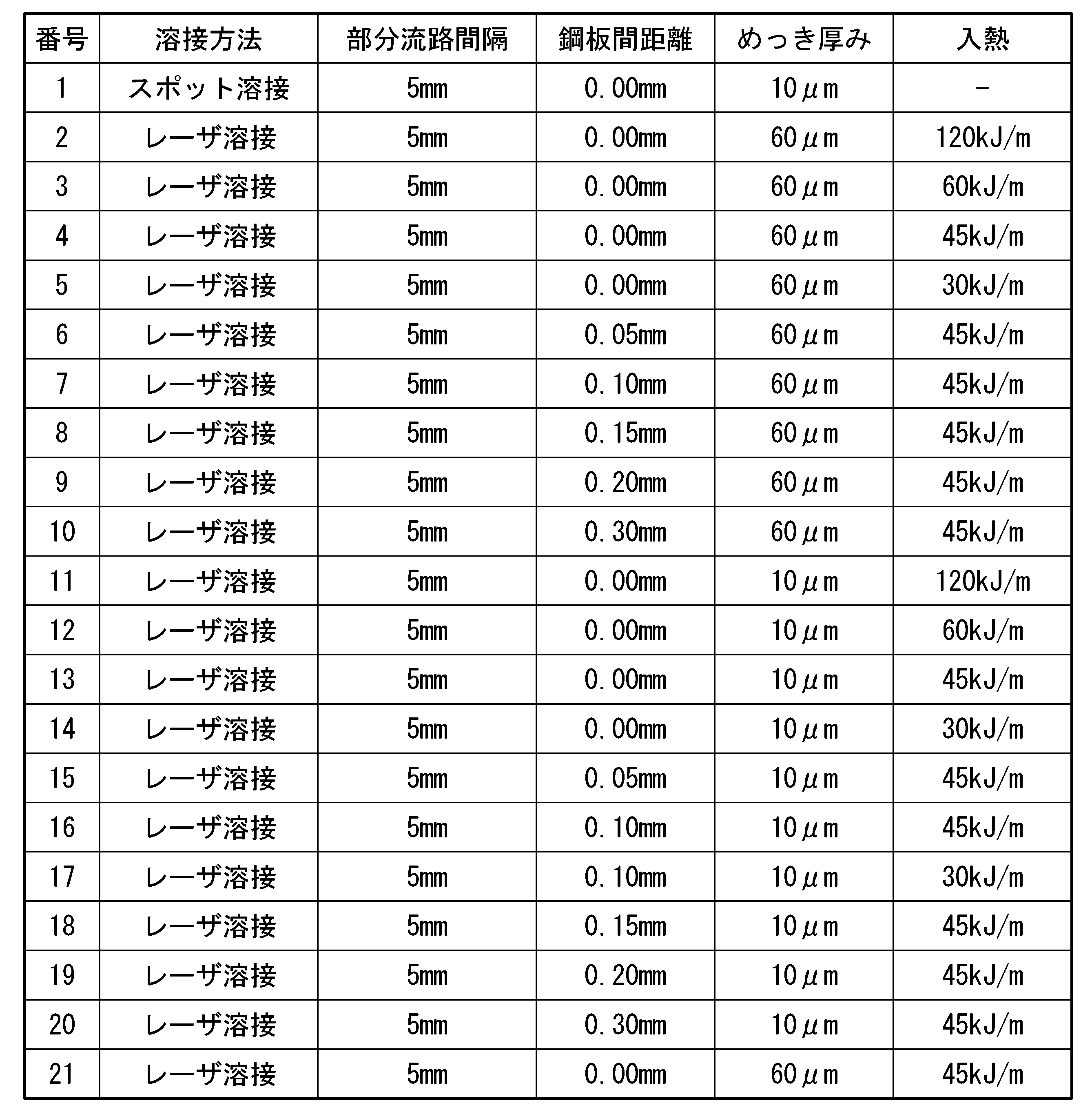

11 プレス成形部材
111 溝部
112 堤部
12 流路上蓋
13 レーザ溶接部
13A 流路外縁溶接部
131 始端部
132 終端部
133 中間部
14 流路
141 並列流路部
1411 部分流路
142 流路連通部
143 冷却液入口
144 冷却液出口
15 母材鋼板
16 Al系めっき
2 バッテリーユニット
21 電池セル
22 バッテリーパック
23 ギャップフィラー
R 堤部の曲率半径を示す円
T タブ板
L レーザ
D 流路の間隔
W 流路の幅
Claims (19)
- 溝部、及び、前記溝部の周囲に設けられた堤部を有するプレス成形部材と、
前記プレス成形部材の前記溝部を覆う位置に重ねられた平板であって、平坦な冷却面を構成する流路上蓋と、
前記流路上蓋と前記堤部との互いに対向する面同士を接合して、冷却液が流通可能な流路を形成するレーザ溶接部と、
を備え、
前記プレス成形部材及び前記流路上蓋は、母材鋼板と、Al系めっきとを有するめっき鋼板であり、
前記流路は、第1方向に沿って延びる複数の部分流路が前記第1方向と直交する第2方向に並ぶ並列流路部を有し、
前記並列流路部の一部または全部において、隣り合う前記部分流路同士の間隔が20mm以下である
冷却構造。 - 前記並列流路部において、隣り合う前記部分流路同士の間隔が0.8~15mmであることを特徴とする請求項1に記載の冷却構造。
- 前記部分流路の幅が6~60mmであることを特徴とする請求項1又は2に記載の冷却構造。
- 前記部分流路の幅が6~20mmであることを特徴とする請求項1又は2に記載の冷却構造。
- 前記Al系めっきにSiが含まれていることを特徴とする請求項1~4のいずれか一項に記載の冷却構造。
- 前記Al系めっきのSi含有量が2.0~15質量%であることを特徴とする請求項5に記載の冷却構造。
- 前記めっき鋼板が、表面に、Zr系成分、Ti系成分又はSi系成分を50質量%以上の割合で含む化成処理皮膜を有することを特徴とする請求項1~6のいずれか一項に記載の冷却構造。
- 前記堤部の断面形状が略円弧であり、
前記流路上蓋と、前記堤部との接触部における、前記堤部の曲率半径が15mm以下であることを特徴とする請求項1~7のいずれか一項に記載の冷却構造。 - 前記Al系めっきの膜厚が10.0μm以上であり、
前記レーザ溶接部の近傍における、前記プレス成形部材と前記流路上蓋との間隔が0.3mm以下であり、
前記流路上蓋における前記レーザ溶接部の表面のビード幅、及び前記プレス成形部材における前記レーザ溶接部の表面のビード幅のうち太い方が、0.8~1.5mmである
ことを特徴とする請求項1~8のいずれか一項に記載の冷却構造。 - 前記プレス成形部材及び前記流路上蓋を構成する前記めっき鋼板の板厚が0.3~1.2mmであることを特徴とする請求項1~9のいずれか一項に記載の冷却構造。
- 前記レーザ溶接部が、全ての前記流路を包囲する流路外縁溶接部を有し、
前記レーザ溶接部の始端及び終端が、前記流路外縁溶接部から除外されている
ことを特徴とする請求項1~10のいずれか一項に記載の冷却構造。 - 前記冷却構造から、前記レーザ溶接部の始端部及び終端部が除かれていることを特徴とする請求項1~11のいずれか一項に記載の冷却構造。
- 前記プレス成形部材及び前記流路上蓋の間において、前記レーザ溶接部の表面の一部又は全部が前記Al系めっきによって覆われていることを特徴とする請求項1~12のいずれか一項に記載の冷却構造。
- 前記プレス成形部材及び前記流路上蓋の間において、前記レーザ溶接部の表面の30%以上が前記Al系めっきによって覆われていることを特徴とする請求項1~13のいずれか一項に記載の冷却構造。
- 前記流路上蓋における、前記レーザ溶接部のビード高さが0.3mm以下であることを特徴とする請求項1~14のいずれか一項に記載の冷却構造。
- 電池セルと、
前記電池セルが収納されたバッテリーパックと、
請求項1~15のいずれか一項に記載の冷却構造と
を備え、
前記冷却構造の前記流路上蓋が前記バッテリーパックに接合されているバッテリーユニット。 - 電池セルと、
前記電池セルが収納されたバッテリーパックと、
請求項1~15のいずれか一項に記載の冷却構造と
を備え、
前記冷却構造の前記流路上蓋が前記バッテリーパックであるバッテリーユニット。 - 鋼板をプレス成形して、溝部、及び、前記溝部の周囲に設けられた堤部を有するプレス成形部材を得る工程と、
平板である流路上蓋を、前記プレス成形部材の前記溝部を覆う位置に重ね、前記流路上蓋と前記プレス成形部材の前記堤部とをレーザ溶接して、冷却液が流通可能な流路を形成するレーザ溶接部を得る工程と、
を備え、
前記プレス成形部材及び前記流路上蓋は、母材鋼板と、Al系めっきとを有するめっき鋼板であり、
前記流路は、第1方向に沿って延びる複数の部分流路が前記第1方向と直交する第2方向に並ぶ並列流路部を有し、
前記並列流路部において、隣り合う前記部分流路同士の間隔が20mm以下である
冷却構造の製造方法。 - 前記Al系めっきの膜厚が10.0μm以上であり、
前記レーザ溶接において、ビーム径を0.2~0.8mmとし、単位溶接長当たりの入熱を30~120kJ/mとし、かつ、
前記レーザ溶接部の近傍における、前記プレス成形部材と前記流路上蓋との間隔を0.3mm以下とすることを特徴とする請求項18に記載の冷却構造の製造方法。
Priority Applications (4)
| Application Number | Priority Date | Filing Date | Title |
|---|---|---|---|
| JP2023522337A JPWO2022244570A1 (ja) | 2021-05-20 | 2022-04-15 | |
| CN202280035590.4A CN117321836A (zh) | 2021-05-20 | 2022-04-15 | 冷却结构、电池装置及冷却结构的制造方法 |
| EP22804484.8A EP4343926A1 (en) | 2021-05-20 | 2022-04-15 | Cooling structure, battery unit, and cooling structure manufacturing method |
| KR1020237039816A KR20230173707A (ko) | 2021-05-20 | 2022-04-15 | 냉각 구조, 배터리 유닛, 및 냉각 구조의 제조 방법 |
Applications Claiming Priority (2)
| Application Number | Priority Date | Filing Date | Title |
|---|---|---|---|
| JP2021085188 | 2021-05-20 | ||
| JP2021-085188 | 2021-05-20 |
Publications (1)
| Publication Number | Publication Date |
|---|---|
| WO2022244570A1 true WO2022244570A1 (ja) | 2022-11-24 |
Family
ID=84141324
Family Applications (1)
| Application Number | Title | Priority Date | Filing Date |
|---|---|---|---|
| PCT/JP2022/017942 WO2022244570A1 (ja) | 2021-05-20 | 2022-04-15 | 冷却構造、バッテリーユニット、及び冷却構造の製造方法 |
Country Status (5)
| Country | Link |
|---|---|
| EP (1) | EP4343926A1 (ja) |
| JP (1) | JPWO2022244570A1 (ja) |
| KR (1) | KR20230173707A (ja) |
| CN (1) | CN117321836A (ja) |
| WO (1) | WO2022244570A1 (ja) |
Citations (13)
| Publication number | Priority date | Publication date | Assignee | Title |
|---|---|---|---|---|
| JP3302676B2 (ja) | 2000-11-07 | 2002-07-15 | 日新製鋼株式会社 | 耐食性に優れた化成処理鋼板 |
| JP2004232040A (ja) | 2003-01-31 | 2004-08-19 | Nippon Steel Corp | 耐食性、塗装性及び加工性に優れるアルミめっき鋼板 |
| JP2008115442A (ja) | 2006-11-07 | 2008-05-22 | Nippon Steel Corp | 加熱時の耐変色性、加熱後耐食性に優れたアルミめっき鋼材およびその水系処理薬剤。 |
| JP4776458B2 (ja) | 2005-07-22 | 2011-09-21 | 新日本製鐵株式会社 | 耐食性、耐熱性、耐指紋性、導電性、塗装性および加工時の耐黒カス性に優れたクロメートフリー表面処理金属材 |
| JP2012017954A (ja) | 2010-07-09 | 2012-01-26 | Nisshin Steel Co Ltd | 冷却器 |
| JP2013007108A (ja) | 2011-06-27 | 2013-01-10 | Nippon Steel & Sumitomo Metal Corp | 表面処理アルミめっき鋼板とその製造方法 |
| JP5336002B2 (ja) | 2011-04-27 | 2013-11-06 | 新日鐵住金株式会社 | 表面処理金属材及び水系金属表面処理剤 |
| JP6125624B2 (ja) | 2012-06-11 | 2017-05-10 | ジャガー・ランド・ローバー・リミテッドJaguar Land Rover Limited | 車両用電池パック、電池パックを冷却するためのシステム及び該システムで使用するための冷却板 |
| WO2019076813A1 (de) * | 2017-10-16 | 2019-04-25 | Reinz-Dichtungs-Gmbh | Elektrochemische anordnung und elektrochemisches system |
| JP2020038814A (ja) * | 2018-09-06 | 2020-03-12 | 本田技研工業株式会社 | 接合セパレータの製造方法及び製造装置 |
| JP2020107443A (ja) | 2018-12-26 | 2020-07-09 | 株式会社デンソー | 電池冷却システム |
| JP2021012838A (ja) * | 2019-07-09 | 2021-02-04 | 本田技研工業株式会社 | 燃料電池スタック |
| JP2021085188A (ja) | 2019-11-26 | 2021-06-03 | 株式会社奥村組 | 柱梁接合部構造 |
-
2022
- 2022-04-15 JP JP2023522337A patent/JPWO2022244570A1/ja active Pending
- 2022-04-15 EP EP22804484.8A patent/EP4343926A1/en active Pending
- 2022-04-15 KR KR1020237039816A patent/KR20230173707A/ko unknown
- 2022-04-15 CN CN202280035590.4A patent/CN117321836A/zh active Pending
- 2022-04-15 WO PCT/JP2022/017942 patent/WO2022244570A1/ja active Application Filing
Patent Citations (13)
| Publication number | Priority date | Publication date | Assignee | Title |
|---|---|---|---|---|
| JP3302676B2 (ja) | 2000-11-07 | 2002-07-15 | 日新製鋼株式会社 | 耐食性に優れた化成処理鋼板 |
| JP2004232040A (ja) | 2003-01-31 | 2004-08-19 | Nippon Steel Corp | 耐食性、塗装性及び加工性に優れるアルミめっき鋼板 |
| JP4776458B2 (ja) | 2005-07-22 | 2011-09-21 | 新日本製鐵株式会社 | 耐食性、耐熱性、耐指紋性、導電性、塗装性および加工時の耐黒カス性に優れたクロメートフリー表面処理金属材 |
| JP2008115442A (ja) | 2006-11-07 | 2008-05-22 | Nippon Steel Corp | 加熱時の耐変色性、加熱後耐食性に優れたアルミめっき鋼材およびその水系処理薬剤。 |
| JP2012017954A (ja) | 2010-07-09 | 2012-01-26 | Nisshin Steel Co Ltd | 冷却器 |
| JP5336002B2 (ja) | 2011-04-27 | 2013-11-06 | 新日鐵住金株式会社 | 表面処理金属材及び水系金属表面処理剤 |
| JP2013007108A (ja) | 2011-06-27 | 2013-01-10 | Nippon Steel & Sumitomo Metal Corp | 表面処理アルミめっき鋼板とその製造方法 |
| JP6125624B2 (ja) | 2012-06-11 | 2017-05-10 | ジャガー・ランド・ローバー・リミテッドJaguar Land Rover Limited | 車両用電池パック、電池パックを冷却するためのシステム及び該システムで使用するための冷却板 |
| WO2019076813A1 (de) * | 2017-10-16 | 2019-04-25 | Reinz-Dichtungs-Gmbh | Elektrochemische anordnung und elektrochemisches system |
| JP2020038814A (ja) * | 2018-09-06 | 2020-03-12 | 本田技研工業株式会社 | 接合セパレータの製造方法及び製造装置 |
| JP2020107443A (ja) | 2018-12-26 | 2020-07-09 | 株式会社デンソー | 電池冷却システム |
| JP2021012838A (ja) * | 2019-07-09 | 2021-02-04 | 本田技研工業株式会社 | 燃料電池スタック |
| JP2021085188A (ja) | 2019-11-26 | 2021-06-03 | 株式会社奥村組 | 柱梁接合部構造 |
Also Published As
| Publication number | Publication date |
|---|---|
| JPWO2022244570A1 (ja) | 2022-11-24 |
| EP4343926A1 (en) | 2024-03-27 |
| KR20230173707A (ko) | 2023-12-27 |
| CN117321836A (zh) | 2023-12-29 |
Similar Documents
| Publication | Publication Date | Title |
|---|---|---|
| CN111601911B (zh) | 表面处理溶液组合物、经表面处理的合金化热浸镀锌钢板及其制造方法 | |
| JP6272207B2 (ja) | 化成処理液 | |
| WO2022244570A1 (ja) | 冷却構造、バッテリーユニット、及び冷却構造の製造方法 | |
| US20090129999A1 (en) | Method of brazing a first metal member to a second metal member using a high wettability metal as layer between the two metal members; reformer manufactured by this method, the metal members having grooves | |
| WO2022244569A1 (ja) | 冷却構造、バッテリーユニット、及び冷却構造の製造方法 | |
| WO2022185840A1 (ja) | バッテリーユニット | |
| JP6884083B2 (ja) | 化成処理鋼板 | |
| WO2022149596A1 (ja) | 表面処理鋼板 | |
| JP3814179B2 (ja) | ろう付け用複合材及びそれを用いたろう付け製品 | |
| CN116918141A (zh) | 蓄电池装置 | |
| WO2022244568A1 (ja) | 冷却構造、バッテリーユニット、及び冷却構造の製造方法 | |
| TWI790366B (zh) | 化成處理液及化成處理鋼板 | |
| JP6142750B2 (ja) | 燃料タンク用表面処理鋼板 | |
| CN111441856B (zh) | 具有焊接边缘的扩散表面合金金属排气部件 | |
| JP2013537471A (ja) | コバルト含有コーティングを有する高級鋼の高温耐性コンポーネント、排気ガス浄化装置および該排気ガス浄化装置を製造する方法 | |
| EP4273283A1 (en) | Battery unit | |
| US10094338B2 (en) | Combination structure of EGR cooler | |
| JP4419262B2 (ja) | 高耐食性燃料タンク用鋼板 | |
| JP7476823B2 (ja) | 金属製品 | |
| US10253730B2 (en) | Water-cooled EGR cooler, and the manufacturing method thereof | |
| JP2001279470A (ja) | 高耐食性燃料タンク用鋼板 | |
| WO2014115512A1 (ja) | 熱交換器用チューブ | |
| WO2023190979A1 (ja) | 表面処理鋼板、及び、部品の製造方法 | |
| TWI597387B (zh) | Fuel tank with surface treatment of steel | |
| JP2020029623A (ja) | 化成処理液および化成処理鋼板 |
Legal Events
| Date | Code | Title | Description |
|---|---|---|---|
| 121 | Ep: the epo has been informed by wipo that ep was designated in this application |
Ref document number: 22804484 Country of ref document: EP Kind code of ref document: A1 |
|
| WWE | Wipo information: entry into national phase |
Ref document number: 2023522337 Country of ref document: JP |
|
| WWE | Wipo information: entry into national phase |
Ref document number: 18289564 Country of ref document: US |
|
| ENP | Entry into the national phase |
Ref document number: 20237039816 Country of ref document: KR Kind code of ref document: A |
|
| WWE | Wipo information: entry into national phase |
Ref document number: 1020237039816 Country of ref document: KR |
|
| WWE | Wipo information: entry into national phase |
Ref document number: 2022804484 Country of ref document: EP |
|
| NENP | Non-entry into the national phase |
Ref country code: DE |
|
| ENP | Entry into the national phase |
Ref document number: 2022804484 Country of ref document: EP Effective date: 20231220 |