WO2022239874A1 - 切断システム及び切断装置 - Google Patents
切断システム及び切断装置 Download PDFInfo
- Publication number
- WO2022239874A1 WO2022239874A1 PCT/JP2022/020299 JP2022020299W WO2022239874A1 WO 2022239874 A1 WO2022239874 A1 WO 2022239874A1 JP 2022020299 W JP2022020299 W JP 2022020299W WO 2022239874 A1 WO2022239874 A1 WO 2022239874A1
- Authority
- WO
- WIPO (PCT)
- Prior art keywords
- cutting
- cut
- cutting blade
- main body
- guide unit
- Prior art date
- Legal status (The legal status is an assumption and is not a legal conclusion. Google has not performed a legal analysis and makes no representation as to the accuracy of the status listed.)
- Ceased
Links
Images



Classifications
-
- B—PERFORMING OPERATIONS; TRANSPORTING
- B26—HAND CUTTING TOOLS; CUTTING; SEVERING
- B26D—CUTTING; DETAILS COMMON TO MACHINES FOR PERFORATING, PUNCHING, CUTTING-OUT, STAMPING-OUT OR SEVERING
- B26D7/00—Details of apparatus for cutting, cutting-out, stamping-out, punching, perforating, or severing by means other than cutting
- B26D7/08—Means for treating work or cutting member to facilitate cutting
Definitions
- the present invention relates to a cutting system and a cutting device.
- An object of the present invention is to realize a technique for cutting sheet-shaped members more appropriately.
- a cutting system includes: a main body having a vibrator that applies ultrasonic vibrations to the cutting blade; A guide portion for accommodating a tip portion of the cutting blade protruding from the main body, and a connecting portion for connecting the guide portion to the main body.
- a guide unit having a space and having a part of the cutting blade exposed in the cutting space;
- a cutting device comprising a conveying device that relatively moves the cutting device and the cutting object; characterized by comprising
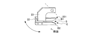
- FIG. 3 is a schematic diagram (side view) showing a specific configuration example of the cutting device 20.
- FIG. FIG. 3 is a schematic diagram (perspective view) showing a configuration example of a guide unit 20B;
- FIG. 11 is a schematic diagram showing an example (standard posture) of a connection angle of the guide unit 20B with respect to the main body 20A;
- FIG. 10 is a schematic diagram showing an example of a connection angle (retracted posture) of the guide unit 20B with respect to the main body 20A;
- FIG. 4 is a schematic diagram showing an example of a connection angle of the guide unit 20B with respect to the main body 20A (acute-angle cutting posture).
- FIG. 11 is a schematic diagram (before guiding the film 110) showing the operation of cutting the object to be cut by the guide unit 20B set in the standard posture
- FIG. 10 is a schematic diagram showing the operation of cutting the object to be cut by the guide unit 20B set in the standard posture (at the time of cutting the film 110);
- FIG. 10 is a schematic diagram (side view) showing the operation of cutting an object to be cut by the guide unit 20B set in the retracted posture;
- FIG. 10 is a schematic diagram (rear view) showing the operation of cutting a cutting target with the guide unit 20B set in the retracted posture;
- FIG. 2 is a schematic diagram showing a configuration example of a cutting device 20 that forms a cutting space S only on the upstream side of a cutting blade 21;
- FIG. 11 is a schematic diagram showing a configuration example in which the guide unit 20B is in a retracted posture by moving the guide portion 22 in parallel;
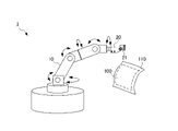
- FIG. 1 is a schematic diagram showing the overall configuration of a cutting system 1 according to the present invention.
- the cutting system 1 is a device for cutting a film 110, and in particular, can easily cut the film 110 attached to a work 100 having a three-dimensional shape (such as a curved shape) along the work 100 in an arbitrary posture. have a configuration.
- the member referred to as the film 110 includes various items attached to the workpiece 100, including attached materials referred to as films, stickers, sheets, webs, and the like.
- the cutting system 1 includes an articulated robot 10 and a cutting device 20 .
- the articulated robot 10 (conveying device) is composed of, for example, a 6-axis vertical articulated robot or the like. cut the film 110 to which is attached.
- the cutting device 20 has a cutting blade 21 to which ultrasonic vibrations are applied by an ultrasonic vibrator, and cuts the film 110 while guiding the film 110 to the cutting blade 21 .
- the cutting blade 21 is covered with a guide unit 20B (described later), and a part of the guide unit 20B is opened. A part of the blade 21 is exposed.
- the articulated robot 10 equipped with the cutting device 20 moves the cutting device 20 while changing its attitude.
- the film 110 can be cut by the cutting blade 21 while being guided to the opening of the guide unit 20B.
- FIG. 2 is a schematic diagram (side view) showing a specific configuration example of the cutting device 20.
- the cutting device 20 in the cutting system 1, includes a main body 20A and a guide unit 20B, and the guide unit 20B is rotatably connected to the main body 20A.
- the main body 20A incorporates an ultrasonic transducer 30 that imparts ultrasonic vibration to the cutting blade 21, and the cutting blade 21 is installed at the tip of the ultrasonic transducer 30.
- the cutting blade 21 reciprocates in a direction protruding from the main body 20A by being subjected to ultrasonic vibration by the ultrasonic vibrator 30, and cuts the object to be cut (here, the film 110).
- FIG. 3 is a schematic diagram (perspective view) showing a configuration example of the guide unit 20B.
- the guide unit 20B includes a guide portion 22 and a connecting portion 23.
- the guide portion 22 has a groove portion 221 that accommodates the tip of the cutting blade 21 protruding from the main body 20A. Further, the guide portion 22 has a cutting space S into which an object to be cut is introduced, and a part of the cutting blade 21 is exposed in the cutting space S.
- the guide portion 22 has a bifurcated structure in which one end portion (the right end portion in FIGS. 2 and 3) is composed of an upper branch B1 and a lower branch B2 in a side view. Between the upper branch B1 and the lower branch B2 is a cutting space S into which an object to be cut is introduced, and between the tip of the upper branch B1 and the tip of the lower branch B2 , an opening E for receiving an object to be cut.
- the tip of the upper branch B1 and the tip of the lower branch B2 are tapered, and the opening E of the cutting space S is formed at the tip of the upper branch B1 and the lower branch B2.
- the opening width increases as it approaches As a result, a structure that facilitates introduction of the cutting object into the space S for cutting can be realized.
- the width of the opening E is such that a human finger or the like does not come into contact with the cutting blade 21 in order to prevent the operator's body from coming into contact with the cutting blade 21 .
- a part of the cutting blade 21 accommodated in the groove 221 is exposed in the cutting space S. Therefore, when an object to be cut is introduced into the cutting space S from the opening E, the object to be cut contacts the cutting blade 21 while being guided by the upper branch B1 and the lower branch B2, causing ultrasonic vibration.
- the object to be cut is cut by the cutting blade 21 imparted with .
- the connecting portion 23 connects the guide portion 22 and the main body 20A, and is rotatably installed with respect to the main body 20A via a rotating portion 231.
- the guide unit 20B can change to a posture connected at different connection angles by rotating around the rotation axis of the rotating portion 231 with respect to the main body 20A.
- FIG. 4 to 6 are schematic diagrams showing an example of the connection angle of the guide unit 20B with respect to the main body 20A, and FIG. (hereinafter referred to as "standard posture”).
- standard posture the guide portion 22 rotates to the side opposite to the retracted posture (the side where the object to be cut is introduced), and the cutting blade 21 cuts into the object to be cut at an acute angle.
- the posture hereinafter referred to as "acute angle cutting posture" is shown.
- the connecting portion 23 rotates around the rotating shaft of the rotating portion 231, thereby rotating the guide portion 22 to the side opposite to the retracted posture (the side to which the object to be cut is introduced). Then, from the acute angle cutting posture in which the cutting blade 21 cuts the object to be cut at an acute angle, through the standard posture in which the guide portion 22 accommodates the tip of the cutting blade 21 in the groove portion 221, the guide portion 22 moves the tip of the cutting blade 21.
- the posture of the guide unit 20B can be held in any posture from the stored posture to the retracted posture that does not interfere with the cutting object to be cut by the cutting blade 21 .
- the cutting blade 21 forms a guide portion 22 (specifically, the upper branch B1 and the lower branch B2) in the cutting space S.
- the intersection angle can be changed.
- the intersection angle between the cutting blade 21 and the lower branch B2 of the guide portion 22 is 80 degrees in the cutting space S
- the crossing angle between the cutting blade 21 and the lower branch B2 of the guide portion 22 is 60 degrees. This makes it possible to change the angle at which the cutting blade 21 cuts into the object to be cut according to the characteristics of the object to be cut.
- FIG. 7 is a schematic diagram showing an example of a cutting object.
- a resin film 110 is attached to a work 100 that is a glass substrate, and that the periphery of the work 100 has convex and concave bent portions.
- area A1 is an area where the film 110 protrudes from the work 100 and one end is a free end
- area A2 is an area where the film 110 is supported by the work 100 near the periphery of the work 100
- area A3 is an area where the peripheral edge of the workpiece 100 is bent in a concave shape, and when the film 110 is cut, the cutting device 20 and the workpiece 100 are likely to interfere with each other.
- FIG. 8 and 9 are schematic diagrams showing the operation of cutting the object to be cut by the guide unit 20B set in the standard posture.
- FIG. FIG. 9 shows a state before the film 110 is guided to the cutting space S, and shows a state in which the film 110 is guided to the cutting space S of the guiding portion 22 and cut by the cutting blade 21 .
- a cutting device 20 is mounted as a tool of an articulated robot 10, and an object to be cut (film 110) is cut while the position and posture of the cutting device 20 are arbitrarily controlled by the articulated robot 10. can be done.
- the cutting system 1 cuts the film 110
- the work 100 to which the film 110 is attached is held in a space within the range of motion of the articulated robot 10 by sucking the work 100 or the like.
- one end of the peripheral portion of the film 110 protruding from the work 100 is a free end and is in a state where no tension is applied.
- the guide unit 20B is set in the standard posture with respect to the periphery of the film 110, which is a free end. is guided to the space S for cutting.
- the film 110 can be easily introduced. Then, as shown in FIG. 9, the film 110 comes into contact with the cutting blade 21 while being supported by the upper branch B1 and the lower branch B2 of the guide portion 22 . As a result, the film 110, which is a free end such as the area A1, can be properly cut.
- FIGS. 10 and 11 are schematic diagrams showing how the guide unit 20B set in the retracted posture cuts the object to be cut.
- FIG. 10 cuts the film 110 near the periphery of the work 100.
- FIG. 11 is a side view of the state, and
- FIG. 11 is a rear view of the state in which the film 110 is cut near the periphery of the workpiece 100.
- FIG. 10 and 11 since the film 110 is attached to the work 100 near the periphery of the work 100, a certain supporting force acts on the film 110. As shown in FIGS. Therefore, the film 110 can be cut without using the supporting force of the guide unit 20B.
- the unused guide unit 20B can be prevented from interfering with the workpiece 100 or the film 110 to be cut, and the film 110 can be cut appropriately. That is, the film 110 near the periphery of the workpiece 100 such as the area A2 can be cut appropriately.
- the guide unit 20B is also in a portion such as the area A3 where the peripheral edge of the work 100 is bent in a concave shape and the cutting device 20 and the work 100 are likely to interfere with each other. Interference with the workpiece 100 can be avoided, and the film 110 can be properly cut.
- the film 110 can be cut along the periphery of the workpiece 100 by easily changing the traveling direction of the cutting blade 21 . That is, the film 110 can be appropriately cut at a portion where the cutting device 20 and the work 100 are likely to interfere with each other, such as the area A3.
- the cutting position of the film 110 can be detected without cutting the film 110 from the periphery. ) to start cutting. As a result, it is possible to flexibly select a cutting method for cutting the film 110 .
- the cutting device 20 is attached to the articulated robot 10, and the articulated robot 10 controls the cutting device 20 to an arbitrary position and orientation while the guide unit 20B is operated.
- An unnecessary portion of the object to be cut (film 110) attached to the workpiece 100 is cut by the cutting blade 21 partially exposed in the cutting space S.
- the width of the opening E of the cutting space S is widened, the object to be cut can be easily introduced into the cutting space S.
- the object to be cut that comes into contact with the cutting blade 21 to which the ultrasonic vibration is applied is cut while being supported by the upper branch B1 and the lower branch B2 of the guide portion 22 . Therefore, according to the cutting system 1, it is possible to cut the sheet-shaped member more appropriately.
- the tip of the cutting blade 21 is accommodated in the guide portion 22, and only a part thereof is exposed to the cutting space S. ) and the cutting blade 21 can be prevented from coming into contact with each other.
- the cutting device 20 and the workpiece 100 are configured so as not to interfere with each other. That is, in the standard posture and the acute-angle cutting posture, the main body 20A of the cutting device 20 is offset from the position of the cutting space S to the opposite side (for example, the upper side in FIG. 2) across the rotating part 231. It is Therefore, according to the cutting system 1, it is possible to cut the film 110 at a position close to the edge of the workpiece 100 in the standard posture and the sharp cutting posture.
- the adjacent surfaces (the front surface and the back surface) can be cut. ), only the film 110 to be cut can be reliably guided inside from the opening E of the cutting space S, and the film 110 can be cut appropriately.
- FIG. 12 is a schematic diagram showing a configuration example of the cutting device 20 that forms the cutting space S only on the upstream side of the cutting blade 21. As shown in FIG. In the configuration example shown in FIG.
- the cutting space S of the guiding portion 22 does not extend downstream where the object to be cut (film 110) relatively moves with respect to the cutting blade 21 in the standard posture, and does not extend to the opening E. to the position of the cutting blade 21 .
- the object to be cut it is possible to prevent the object to be cut from entering the space on the downstream side of the cutting blade 21 after cutting.
- FIG. 13 is a schematic diagram showing a configuration example in which the guide unit 20B is in the retracted posture by moving the guide portion 22 in parallel.
- the cutting device 20 in this modified example is installed on the main body 20A side, and moves the guide portion 22 in the horizontal direction (direction along the relative movement direction of the object to be cut).
- the guide unit 20B can also be in the retracted posture.
- the conveying device such as the articulated robot 10 moves the cutting device 20 to cut an object to be cut (such as the film 110), moves the object to be cut with respect to the cutting device 20, or moves the object to be cut.
- the object to be cut and the cutting device 20 can be relatively moved in various forms, such as moving the object and the cutting device 20 together, to cut the object to be cut.
- an actuator may be provided for changing the angle of the guide unit 20B with respect to the main body 20A (standard posture, retracted posture, sharp cutting posture, etc.).
- an actuator that rotates the rotating portion 231 may be installed in the cutting device 20, and the actuator may be driven to change the angle of the guide unit 20B with respect to the main body 20A. Accordingly, the angle of the guide unit 20B with respect to the main body 20A (that is, the crossing angle between the cutting blade 21 and the lower branch B2 of the guide portion 22) is adjusted to an appropriate state according to the characteristics of the object to be cut. , the object to be cut can be cut.
- the guide unit 20B is rotated around the rotating portion 231 by the operation of the articulated robot 10 or a separately provided robot arm or the like, and the guide unit 20B relative to the main body 20A is rotated. It is also possible to change the angle of For example, it is possible to change the angle of the guide unit 20B with respect to the main body 20A by operating the articulated robot 10 and pressing the guide unit 20B against a predetermined fixed member or the like. Further, the cutting device 20 held by the articulated robot 10 can be operated to rotate the guide unit 20B by a mechanism such as a separately provided robot arm to change the angle of the guide unit 20B with respect to the main body 20A. It is possible.
- the present invention is not limited to this. That is, the cutting blade 21 between the main body 20A and the guide portion 22 can be covered with a member such as the connecting portion 23. As shown in FIG. Moreover, it is possible to adopt a configuration in which the configurations of the above-described embodiment, modifications, and the like are appropriately combined.
- the cutting system 1 in this embodiment includes the articulated robot 10 and the cutting device 20, and the cutting device 20 includes the main body 20A and the guide unit 20B.
- the main body 20A has an ultrasonic vibrator 30 that applies ultrasonic vibration to the cutting blade 21 .
- the guide unit 20B includes a guide portion 22 that accommodates the distal end portion of the cutting blade 21 protruding from the body 20A, and a connecting portion 23 that connects the guide portion 22 to the body 20A. It has a cutting space S into which an object is introduced, and a part of the cutting blade 21 is exposed in the cutting space S.
- the articulated robot 10 relatively moves the cutting device 20 and the object to be cut.
- the film 110 can be supported by the guide portion 22, so that the film 110 can be properly cut even when no tension is applied to the film 110. can be cut. Therefore, according to the cutting system 1, it is possible to cut the sheet-shaped member more appropriately.
- the width of the opening E of the cutting space S in the guide unit 20B increases toward the opening end. This makes it possible to easily introduce the cutting object into the space S for cutting.
- the guide unit 20B is retracted to a posture that accommodates the tip protruding from the main body 20A of the cutting blade 21 and a position that exposes the tip protruding from the main body 20A of the cutting blade 21 and does not interfere with the cutting object to be cut. It is possible to switch between postures. This prevents the guide unit 20B from interfering with the work 100 even in a portion where the cutting device 20 and the work 100 are likely to interfere with each other, so that the film 110 can be cut appropriately.
- the guide unit 20B can adjust the crossing angle between the cutting blade 21 exposed in the cutting space S and the guide portion 22 in a posture in which the tip portion of the cutting blade 21 protruding from the main body 20A is accommodated. This makes it possible to change the angle at which the cutting blade 21 cuts into the object to be cut according to the characteristics of the object to be cut.
- the cutting blade 21 exposed in the cutting space S intersects the guide portion 21 at an acute angle on the side into which the object to be cut is introduced. .
- the action of sandwiching the film 110 between the cutting blade 21 and the branch B2 on the lower side of the guide portion 22 is enhanced, so that the cut portion of the film 110 can be cut while applying a higher tension.
- the present invention is not limited to the above-described embodiments. Moreover, the effects described in the present embodiment are merely enumerations of the most suitable effects resulting from the present invention, and the effects of the present invention are not limited to those described in the present embodiment.
Landscapes
- Life Sciences & Earth Sciences (AREA)
- Forests & Forestry (AREA)
- Engineering & Computer Science (AREA)
- Mechanical Engineering (AREA)
- Perforating, Stamping-Out Or Severing By Means Other Than Cutting (AREA)
- Nonmetal Cutting Devices (AREA)
Priority Applications (2)
| Application Number | Priority Date | Filing Date | Title |
|---|---|---|---|
| CN202280035011.6A CN117295593A (zh) | 2021-05-14 | 2022-05-15 | 切断系统及切断装置 |
| JP2023521273A JPWO2022239874A1 (https=) | 2021-05-14 | 2022-05-15 |
Applications Claiming Priority (2)
| Application Number | Priority Date | Filing Date | Title |
|---|---|---|---|
| JP2021082835 | 2021-05-14 | ||
| JP2021-082835 | 2021-05-14 |
Publications (1)
| Publication Number | Publication Date |
|---|---|
| WO2022239874A1 true WO2022239874A1 (ja) | 2022-11-17 |
Family
ID=84028338
Family Applications (1)
| Application Number | Title | Priority Date | Filing Date |
|---|---|---|---|
| PCT/JP2022/020299 Ceased WO2022239874A1 (ja) | 2021-05-14 | 2022-05-15 | 切断システム及び切断装置 |
Country Status (3)
| Country | Link |
|---|---|
| JP (1) | JPWO2022239874A1 (https=) |
| CN (1) | CN117295593A (https=) |
| WO (1) | WO2022239874A1 (https=) |
Citations (3)
| Publication number | Priority date | Publication date | Assignee | Title |
|---|---|---|---|---|
| JPS58140095U (ja) * | 1982-03-17 | 1983-09-20 | 日産自動車株式会社 | 穿孔ユニツト |
| JPH0187896U (https=) * | 1987-11-30 | 1989-06-09 | ||
| WO2008013138A1 (en) * | 2006-07-25 | 2008-01-31 | Rosecc Co Ltd | Method and device for automatic three-dimensional cutting |
-
2022
- 2022-05-15 JP JP2023521273A patent/JPWO2022239874A1/ja active Pending
- 2022-05-15 CN CN202280035011.6A patent/CN117295593A/zh active Pending
- 2022-05-15 WO PCT/JP2022/020299 patent/WO2022239874A1/ja not_active Ceased
Patent Citations (3)
| Publication number | Priority date | Publication date | Assignee | Title |
|---|---|---|---|---|
| JPS58140095U (ja) * | 1982-03-17 | 1983-09-20 | 日産自動車株式会社 | 穿孔ユニツト |
| JPH0187896U (https=) * | 1987-11-30 | 1989-06-09 | ||
| WO2008013138A1 (en) * | 2006-07-25 | 2008-01-31 | Rosecc Co Ltd | Method and device for automatic three-dimensional cutting |
Also Published As
| Publication number | Publication date |
|---|---|
| CN117295593A (zh) | 2023-12-26 |
| JPWO2022239874A1 (https=) | 2022-11-17 |
Similar Documents
| Publication | Publication Date | Title |
|---|---|---|
| KR101153196B1 (ko) | 초음파 트림장치 | |
| JP6764259B2 (ja) | 電子部品挿入装置 | |
| JP2003181787A (ja) | 多指ハンド装置 | |
| US11389952B2 (en) | Robot arm | |
| JP2018008820A (ja) | ワーク搬送装置およびその運転方法 | |
| JP2026012431A (ja) | 切断システム、切断装置及びカッターユニット | |
| CN117917217A (zh) | 剔骨用刀具组件 | |
| WO2022239874A1 (ja) | 切断システム及び切断装置 | |
| JP6616060B2 (ja) | 貼付装置及び貼付方法 | |
| CN102414103A (zh) | 双面粘合带粘贴装置 | |
| WO2016129526A1 (ja) | エンドエフェクタ及びロボット | |
| JP2020172389A (ja) | 粘着テープ貼付装置、および粘着テープの貼付方法 | |
| JP2025033710A (ja) | テープ材の貼付装置 | |
| JP7361275B2 (ja) | テープ切断装置およびブレードの調整方法 | |
| JP2018024205A (ja) | シール貼付装置 | |
| JP2000084888A (ja) | シート材切断装置 | |
| CN118723508B (zh) | 一种排线换边系统 | |
| JP3072557B2 (ja) | ミシン目カッター装置 | |
| JPH0539837Y2 (https=) | ||
| CN118106786B (zh) | 可调节自由度变力的多轴加工机床 | |
| JP3157227B2 (ja) | シート切断装置 | |
| JP2026057799A (ja) | テープ材の貼付装置 | |
| CN117774016A (zh) | 一种海绵裁切机构及含有其的海绵裁切单元 | |
| JP2023053474A (ja) | テープ材貼付け機およびコンピュータプログラム | |
| JP3422327B2 (ja) | 接木ロボット |
Legal Events
| Date | Code | Title | Description |
|---|---|---|---|
| 121 | Ep: the epo has been informed by wipo that ep was designated in this application |
Ref document number: 22807572 Country of ref document: EP Kind code of ref document: A1 |
|
| WWE | Wipo information: entry into national phase |
Ref document number: 2023521273 Country of ref document: JP |
|
| WWE | Wipo information: entry into national phase |
Ref document number: 202280035011.6 Country of ref document: CN |
|
| NENP | Non-entry into the national phase |
Ref country code: DE |
|
| WWE | Wipo information: entry into national phase |
Ref document number: 11202308582R Country of ref document: SG |
|
| 122 | Ep: pct application non-entry in european phase |
Ref document number: 22807572 Country of ref document: EP Kind code of ref document: A1 |