WO2022239779A1 - コンバイン及び方法 - Google Patents
コンバイン及び方法 Download PDFInfo
- Publication number
- WO2022239779A1 WO2022239779A1 PCT/JP2022/019856 JP2022019856W WO2022239779A1 WO 2022239779 A1 WO2022239779 A1 WO 2022239779A1 JP 2022019856 W JP2022019856 W JP 2022019856W WO 2022239779 A1 WO2022239779 A1 WO 2022239779A1
- Authority
- WO
- WIPO (PCT)
- Prior art keywords
- soil
- taken
- reaping
- harvesting
- detection
- Prior art date
- Legal status (The legal status is an assumption and is not a legal conclusion. Google has not performed a legal analysis and makes no representation as to the accuracy of the status listed.)
- Ceased
Links
Images



Classifications
-
- A—HUMAN NECESSITIES
- A01—AGRICULTURE; FORESTRY; ANIMAL HUSBANDRY; HUNTING; TRAPPING; FISHING
- A01D—HARVESTING; MOWING
- A01D41/00—Combines, i.e. harvesters or mowers combined with threshing devices
- A01D41/12—Details of combines
-
- A—HUMAN NECESSITIES
- A01—AGRICULTURE; FORESTRY; ANIMAL HUSBANDRY; HUNTING; TRAPPING; FISHING
- A01D—HARVESTING; MOWING
- A01D41/00—Combines, i.e. harvesters or mowers combined with threshing devices
- A01D41/12—Details of combines
- A01D41/127—Control or measuring arrangements specially adapted for combines
-
- A—HUMAN NECESSITIES
- A01—AGRICULTURE; FORESTRY; ANIMAL HUSBANDRY; HUNTING; TRAPPING; FISHING
- A01D—HARVESTING; MOWING
- A01D57/00—Delivering mechanisms for harvesters or mowers
-
- A—HUMAN NECESSITIES
- A01—AGRICULTURE; FORESTRY; ANIMAL HUSBANDRY; HUNTING; TRAPPING; FISHING
- A01D—HARVESTING; MOWING
- A01D57/00—Delivering mechanisms for harvesters or mowers
- A01D57/26—Plates arranged behind the cutter-bar for guiding the cut grass or straw
-
- A—HUMAN NECESSITIES
- A01—AGRICULTURE; FORESTRY; ANIMAL HUSBANDRY; HUNTING; TRAPPING; FISHING
- A01D—HARVESTING; MOWING
- A01D61/00—Elevators or conveyors for binders or combines
-
- A—HUMAN NECESSITIES
- A01—AGRICULTURE; FORESTRY; ANIMAL HUSBANDRY; HUNTING; TRAPPING; FISHING
- A01D—HARVESTING; MOWING
- A01D69/00—Driving mechanisms or parts thereof for harvesters or mowers
-
- A—HUMAN NECESSITIES
- A01—AGRICULTURE; FORESTRY; ANIMAL HUSBANDRY; HUNTING; TRAPPING; FISHING
- A01D—HARVESTING; MOWING
- A01D75/00—Accessories for harvesters or mowers
- A01D75/18—Safety devices for parts of the machines
Definitions
- the present invention relates to a combine and a method performed in the combine.
- Patent Document 1 discloses a combine harvester that includes a reaping device, a feeder, and a threshing device.
- the crops harvested by the harvesting device are conveyed to the threshing device by the feeder and threshed.
- the harvesting of crops by the reaper is carried out with the reaper close to the ground.
- the harvesting device moves up and down due to undulations of the ground, etc.
- the soil of the field will be taken into the harvesting device. If soil is taken into the harvesting device, the crops may become soiled and devalued.
- An object of the present invention is to provide means capable of suppressing contamination of crops with soil.
- the combine of the present invention includes a harvesting device for harvesting crops in a field, a conveying device for conveying the crops harvested by the harvesting device, and a crop fed by the conveying device. It is characterized by comprising a threshing device for threshing the grain and a detection device for detecting that soil has been taken into the harvesting device.
- a method performed in a combine having a reaping device and a detection device according to the present invention includes the step of detecting that the detection device has taken soil into the reaping device.
- the detection device detects that soil has been taken into the reaping device.
- the harvesting operation can be stopped and the soil entrained in the harvesting device can be removed.
- the height of the reaper can be adjusted to prevent further soil uptake into the reaper.
- the detection device includes a photographing device and a judgment unit that judges whether soil has been taken in based on the image generated by the photographing device.
- the detection device can be constructed at a relatively low cost. Moreover, since the detection device and the soil can be made non-contact, the durability of the detection device can be enhanced.
- the determination unit includes a machine-learned model that outputs information indicating whether or not soil has been captured in response to the input of the image generated by the imaging device.
- the trained model is generated by machine learning using as input data an image of a state in which soil is taken into the harvesting device, and information designating an area corresponding to the soil in the image as teacher data. It is preferred that
- the detection device has at least a part of the harvesting device and the transport device as a detection target area.
- the soil When the soil is taken into the reaping device, the soil is transported together with the crops by the transport device. According to this configuration, since at least a part of the harvesting device and the conveying device serves as the soil detection target region, it is possible to appropriately detect that the soil has been taken into the harvesting device.
- the reaping device includes a reaping frame, a reaping blade provided across the left and right of the reaping frame, and a reaping blade provided behind the reaping blade across the left and right of the reaping frame and driven to rotate to rotate the crop. and an auger that laterally feeds and conveys the cutting blade, and the detection device preferably defines a detection target region between the cutting blade and the auger.
- a body control unit that changes operating parameters of the body in response to detection by the detection device that soil has been taken into the reaping device.
- the machine body control unit reduces the running speed as the operating parameter in response to the detection device detecting that soil has been taken into the reaping device.
- the machine body control unit changes the traveling speed as the operating parameter to zero in response to the detecting device detecting that soil has been taken into the reaping device.
- the traveling speed becomes zero, so it is possible to suppress the soil being taken into the harvesting device. It is also possible to remove the soil taken into the harvester after the combine has stopped.
- the detection device includes a photographing device and a judgment unit that judges whether or not soil has been taken in based on the image generated by the photographing device.
- an estimating unit that estimates an intake amount, which is the amount of soil that has been collected, using a learned model; and a determination unit that determines a magnitude relationship between the intake amount and a threshold, wherein the intake amount is greater than the threshold It is preferable to determine that soil has been taken into the harvesting device when the determination result of the determining unit indicates that the amount is large.
- the learned model is generated by machine learning using, as input data, an image of a state in which soil is taken into the harvesting device, and information indicating the amount of soil taken in the image as training data. and is suitable.
- an operating tool that accepts input of a human operation
- the determination unit includes a changing unit that changes the threshold value based on the human operation received from the operating tool.
- the detection device it is possible to artificially change the threshold for determining that soil has been taken into the harvesting device, so it is possible to adjust the detection device according to the operator's preference and the required quality of the crop. .
- the threshold value is relatively small, the detection device can detect with a small amount of intake, so that soil staining of crops can be reduced.
- the threshold value is set relatively large, the detection device will not detect a small intake amount, so interruption of work can be suppressed and work efficiency can be improved.
- a notification device and a notification control unit that activates the notification device in response to detection by the detection device that soil has been taken into the reaping device.
- the notification device when the soil is taken into the reaping device, the notification device is activated, so that the operator who receives the notification can take countermeasures, thereby suppressing soil contamination of the crops.
- a notification device and a notification control section for controlling the operation of the notification device are provided, and the detection device includes an estimation section for estimating the intake amount, which is the amount of soil taken into the reaping device.
- the notification control unit notifies the intake amount via the notification device.
- the operator who has received the notification can take measures according to the intake amount, and it is possible to further appropriately suppress soil contamination of the crops.
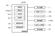
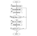
- FIG. 4 is an explanatory diagram of generating a learned model by machine learning using input data and teacher data; It is a flowchart which shows the process performed in a combine.
- a body 1 of a normal type combine (all culm input type combine) includes a harvesting device H, a crawler type traveling device 11, an operation unit 12, a threshing device 13, a grain tank 14, and a conveying device 16. , a grain discharger 18 and an engine E.
- the traveling device 11 is provided at the bottom of the combine. Further, the travel device 11 is driven by power from the engine E. As shown in FIG. The combine can be self-propelled by the travel device 11 . Power from the engine E is changed in speed by a hydraulic continuously variable transmission (HST, not shown) and transmitted to the travel device 11 .
- HST hydraulic continuously variable transmission
- the driving unit 12, the threshing device 13, and the grain tank 14 are provided on the traveling device 11.
- An operator who operates a combine harvester can board the operation unit 12 .
- the grain discharging device 18 is provided on the grain tank 14.
- a harvesting device H is provided at the front of the combine.
- the conveying device 16 is provided behind the harvesting device H. As shown in FIG.
- the harvesting device H also includes a cutting blade 15 and a reel 17 .
- the combine has a reaping cylinder 16A for raising and lowering the reaping device H and the conveying device 16. As shown in FIG. When the reaping cylinder 16A extends, the reaping device H and the transport device 16 are raised. When the reaping cylinder 16A is retracted, the reaping device H and the transport device 16 are lowered.
- the cutting blade 15 cuts crops (planted grain stalks) in the field. Further, the reel 17 rakes the planted grain culms to be harvested while being rotationally driven around the reel axis 17b along the left-right direction of the machine body. The crops (cut grain culms) cut by the cutting blade 15 are sent to the conveying device 16 .
- the reaping device H has a reel 17 that rakes in planted grain culms while being rotationally driven.
- the harvesting device H harvests the crops in the field.
- the combine is capable of reaping travel in which the travel device 11 travels while reaping crops in a field with the reaping blade 15 .
- the crops harvested by the reaping device H are transported to the rear of the fuselage by the transport device 16.
- the crops are thereby conveyed to the threshing device 13 .
- the crops are threshed in the threshing device 13. Grains obtained by the threshing process are stored in the grain tank 14 . The grains stored in the grain tank 14 are discharged out of the machine by the grain discharging device 18 as required.
- the reaping device H is installed in a combine harvester that performs harvesting work in a field. Below, the configuration of the harvesting device H will be described in detail.
- the reaping device H includes a reaping frame 20. As shown in FIG.
- the cutting frame 20 is configured to receive crops cut by the cutting blades 15 .
- the reaping frame 20 has left and right side walls 21 , a rear wall 22 and a bottom plate 23 .
- the rear wall 22 is positioned at the rear end of the reaping frame 20 and extends over the left and right side walls 21 .
- the reaping frame 20 has left and right side walls 21 and a rear wall 22 positioned at the rear end of the reaping frame 20 and extending over the left and right side walls 21 .
- the bottom plate 23 is positioned below the reaping frame 20 .
- the bottom plate 23 is provided so as to extend over the left and right side walls 21 .
- extendable reel cylinders 17A are supported on the upper portions of the left and right side walls 21. As the reel cylinder 17A extends, the reel 17 rises relative to the reaping frame 20. As shown in FIG.
- the reel 17 can move up and down with respect to the reaping frame 20, as shown in FIG. That is, the harvesting device H includes a reel cylinder 17A for raising and lowering the reel 17. As shown in FIG.
- the cutting blade 15 is supported by the bottom plate 23. Further, the cutting blade 15 extends in the left-right direction.
- the cutting blade 15 has a fixed blade 30 and a movable blade 31.
- the fixed blade 30 is provided in a state of protruding forward.
- the fixed blade 30 is supported by the bottom plate 23 .
- the movable blade 31 reciprocates in the lateral direction of the machine body by a driving force transmitted from a movable blade driving mechanism (not shown). As a result, the movable blade 31 reciprocates in the lateral direction of the machine body with respect to the fixed blade 30 .
- the cutting blade 15 cuts planted grain culms with the fixed blade 30 and the movable blade 31 .
- the line P in FIG. 2 indicates the central position of the reaping frame 20 in the lateral direction of the machine body.
- the conveying device 16 is located on the left side of the line P. That is, the conveying device 16 is arranged at a position deviated to the left with respect to the central position of the reaping frame 20 in the lateral direction of the machine body.
- a front end portion of the conveying device 16 is connected to the rear wall 22 so as to communicate with the rear wall 22 .
- the harvesting device H is equipped with an auger 40.
- the auger 40 is rotationally driven around an auger axis 40b.
- the auger axis 40b extends along the left-right direction of the machine body.
- the auger 40 has a first screw body 41, a second screw body 42, and a raking claw 43.
- the first screw body 41 and the second screw body 42 are spirally formed.
- the scraping claw 43 is rod-shaped and protrudes radially outward of the auger 40 .
- the raking claw 43 is provided at a position facing the front end of the conveying device 16 . Further, the first screw body 41 is provided on the right side of the scraping pawl 43 . Further, the second screw body 42 is provided on the left side of the scraping pawl 43 .
- the first screw body 41 conveys the crop received by the reaping frame 20 to the left.
- the second screw body 42 conveys the crop received by the reaping frame 20 to the right.
- the raking claws 43 rake the crops to the rear of the machine body.
- the harvesting device H is provided with left and right dividers 50 projecting forward.
- Left divider 50 is supported at the front end of left side wall 21 .
- a right divider 50 is also supported at the front end of the right side wall 21 .
- the reaping device H includes the reaping frame 20, the reaping blades 15 provided on the left and right sides of the reaping frame 20, and the reaping device H provided behind the reaping blades 15 on the left and right sides of the reaping frame 20 and driven to rotate. and an auger 40 for laterally conveying crops.
- the reaping device H is provided with a dirt cover 51.
- the soil protection cover 51 is an L-shaped plate member extending in the left-right direction of the machine body, and is arranged on the upper surface of the front end portion of the bottom plate 23 in a posture in which the bent portion is positioned upward.
- the dirt guard cover 51 is arranged immediately behind the cutting blade 15 .
- the soil protection cover 51 prevents soil from being taken into the reaping device H in the field.
- the combine includes a photographing device 61, a display input device 62 (an example of an operation tool), a notification device 63, and a control device 80.
- the photographing device 61 is arranged in the front part on the left side of the driving part 12 .
- the photographing device 61 photographs the harvesting device H obliquely from above, generates an image (still image or moving image), and outputs the image to the control device 80 .
- the display input device 62 is configured to be able to receive input of human operation and display information.
- the display input device 62 may be provided in the operation unit 12 or may be a portable information terminal held by the operator.
- the human operation received by the display/input device 62 may be a touch input on the screen, an operation on a key or switch provided to the display/input device 62, or a voice input.
- the notification device 63 is a device that notifies the operator.
- the notification device 63 is, for example, a buzzer, a speaker, a lamp, a display device, a communication device, or the like.
- the display input device 62 may have the function of the notification device 63 .
- the control device 80 is a so-called ECU, and includes a memory (HDD, non-volatile RAM, etc., not shown) that stores programs corresponding to function units to be described later, and a CPU (not shown) that executes the programs. ing. The functions of each functional unit are realized by executing the program by the CPU. That is, the control device 80 has a non-transitory recording medium storing the program.
- the control device 80 includes a determination unit 81, a body control unit 82, and a notification control unit 83 as functional units.
- the determination unit 81 includes an estimation unit 81a, a determination unit 81b, and a change unit 81c. Details of these functional units will be described later.
- the combine is provided with a detection device X for detecting that the reaping device H has taken in soil.
- the detection device X is composed of an imaging device 61 and a determination unit 81 that determines whether or not soil has been captured based on the image generated by the imaging device 61 .
- the detection device X sets at least part of the harvesting device H as a detection target area.
- the detection device X uses the region Y (FIG. 2) between the cutting blade 15 and the auger 40 as the detection target region.
- the photographing device 61 photographs the harvesting device H as a whole.
- a region Y is included in the imaging region of the imaging device 61 . That is, the area Y appears in the image generated by the imaging device 61 .
- the area Y is a rectangular area extending from left to right of the reaping frame 20 .
- the determination by the determination unit 81 is performed as follows in this embodiment.
- the estimating unit 81a estimates the intake amount, which is the amount of soil taken into the harvesting device H, using a learned model.
- the determining unit 81b determines the magnitude relationship between the intake amount estimated by the estimating unit 81a and the threshold.
- the threshold is preset. Then, the determination unit 81 determines that soil has been taken into the harvesting device H when the determination result of the determination unit 81b indicates that the intake amount is greater than the threshold value.
- a plurality of images IM obtained by photographing a state in which soil is taken into the harvesting device H are used as input data, and information IF indicating the amount of taken in each image IM is prepared and used as teacher data.
- the input data may include an image of a state in which the harvesting device H is not loaded with soil.
- a machine learning section 90 which is a functional section of the computer, generates a trained model Z by machine learning using the input data and teacher data.
- the learned model Z is configured to receive an input of an image generated by the photographing device 61, estimate the amount of soil taken in by the reaping device H, and output it.
- the trained model Z generated in this manner is included in the estimation section 81 a of the determination section 81 .
- the machine learning unit 90 may be provided in the control device 80 of the combine, or may be provided outside the combine.
- a pre-generated learned model Z may be provided in the control device 80 when the combine harvester is manufactured.
- the changing unit 81c changes the threshold used for determination by the determination unit 81b based on the human operation received from the display input device 62. For example, the changing unit 81c causes the display/input device 62 to display a screen for accepting a change of the threshold value, and waits for input of a manual operation to the display/input device 62 .
- the machine body control unit 82 changes the operating parameters of the machine body 1 in response to the detection device X detecting that the harvesting device H has taken in soil.
- the following items are exemplified as changes in operation parameters.
- the body control unit 82 decreases the running speed as an operating parameter. Specifically, the body control unit 82 controls the hydraulic continuously variable transmission to reduce the traveling speed of the traveling device 11 .
- the amount of change in the operating parameter can be, for example, a predetermined amount, a decrease up to a predetermined speed, or a decrease according to the amount of soil taken in (the larger the amount of soil taken in, the greater the decrease in travel speed). is.
- the aircraft control unit 82 changes the running speed as an operating parameter to zero. Specifically, the machine body control unit 82 controls the hydraulic continuously variable transmission to gradually decrease the traveling speed of the traveling device 11, finally change the traveling speed to zero, and stop the machine body 1. .
- the machine body control unit 82 increases the height of the harvesting device H as an operating parameter. Specifically, the body control unit 82 controls and extends the reaping cylinder 16A to raise the reaping device H. As shown in FIG.
- the machine body control unit 82 changes the operation state of the harvesting device H as an operation parameter to "stop". Specifically, the machine body control unit 82 controls a reaping clutch (not shown) that turns on and off power transmission from the engine E to the reaping device H to stop the reaping device H.
- a reaping clutch (not shown) that turns on and off power transmission from the engine E to the reaping device H to stop the reaping device H.
- the change in the operating parameters described above may be performed for only one item, or may be performed for a plurality of items simultaneously or sequentially.
- the notification control unit 83 activates the notification device 63 when the detection device detects that the reaping device H has taken in soil. That is, the notification control unit 83 operates the notification device 63 when the determination unit 81 determines that the reaping device H has taken in soil. For example, the notification control unit 83 operates a buzzer and lamp as the notification device 63 .
- the notification control unit 83 causes the display/input device 62 as the notification device 63 to display a screen notifying that soil has been taken in. FIG.
- the notification control unit 83 may be configured to notify the intake amount estimated by the estimation unit 81 a via the notification device 63 .
- the notification control unit 83 causes the display input device 62 as the notification device 63 to display a screen (for example, a bar graph, a numerical value, etc.) indicating the intake amount.
- a trained model Z is generated (step #01).
- the trained model Z is generated when the combine is designed, when the combine is manufactured, or when the combine is used. That is, the generation of the learned model Z is performed before the cutting operation.
- the detection target area is photographed (step #02). Specifically, the photographing device 61 photographs the harvesting device H during execution of the harvesting work.
- the amount of soil taken is estimated (step #03). Specifically, the estimating unit 81a of the determining unit 81 of the control device 80 estimates the intake amount, which is the amount of soil taken into the harvesting device H. As shown in FIG.
- the determining unit 81b determines the magnitude relationship between the intake amount estimated by the estimating unit 81a and the threshold (step #04).
- step #02 is executed again.
- step #05 the operating parameters are changed (step #05). Specifically, the body control unit 82 changes the operating parameters of the body 1 .
- the operating state of the machine body 1 (the traveling speed and the state of the harvesting device H) changes according to the change in the operating parameter.
- the notification device is activated (step #06). Specifically, the notification control unit 83 activates the notification device 63 .
- step #07: No The processing from step #01 to step #06 is repeated until the harvesting work is completed.
- step #07: Yes When the harvesting work ends (step #07: Yes), the process ends.
- step #01 can be omitted if the trained model Z has already been generated.
- Step #07 may be omitted.
- the determination unit 81 may be configured to determine whether soil has been taken in without estimating the taken-in amount, which is the amount of soil taken into the harvesting device H. That is, it is possible to adopt a mode in which the determination unit 81 does not include the estimation unit 81a.
- the determination unit 81 may include a machine-learned model that outputs information indicating whether or not soil has been captured in response to the input of the image generated by the imaging device 61.
- the trained model is generated by machine learning using as input data an image of a state in which soil is taken into the harvesting device H and information designating a region corresponding to the soil in the image as training data.
- the input data may include an image of a state in which the harvesting device H is not loaded with soil.
- the determination unit 81 may include both the trained model of this example and the trained model of the above-described embodiment.
- the detection target area of the detection device X is not limited to the area Y in the above example.
- the detection target area of the detection device X may be the entire harvesting device H.
- the detection target area of the detection device X may be at least part of the conveying device 16 .
- the photographing device 61 is arranged so as to be able to photograph the region of the conveying device 16 where the crops are conveyed.
- the photographing device 61 is provided, for example, at the entrance, inside, or exit of the conveying device 16 .
- the imaging device 61 may be provided at another location.
- the imaging device 61 may be provided at the tip of the grain discharging device 18 .
- a photographing device 61 may be provided at the upper front end portion of the driving portion 12 .
- a combine may be provided with a plurality of imaging devices 61 .
- the photographing device 61 may also be used as a photographing device for other purposes.
- the photographing device 61 may be used as a device (surround view camera) for photographing the surroundings of the machine body 1 of the combine harvester.
- a photographing device 61 provided at the tip of the grain discharging device 18 may be used as a device for photographing the discharge state of grains from the grain discharging device 18 .
- the upper surface of the bottom plate 23 may be colored.
- the top surface of the bottom plate 23 may be colored white, gray, yellow, or other colors so as to be easily distinguished from soil.
- the detection device X may be configured to detect that soil has been taken into the harvesting device H using a Lidar sensor, a weight sensor, a pressure sensor, or the like.
- the detection device X may be configured to detect that soil has been taken into the harvesting device H without relying on a machine-learned model.
- the determination unit 81 of the detection device X may be configured to analyze the image generated by the imaging device 61 and detect that the harvesting device H has taken in soil.
- the determination unit 81 is configured to determine that soil has been taken into the harvesting device H in response to the presence of a soil-colored (brown) region in the detection target region of the image generated by the photographing device 61 . good too.
- the present invention is applicable to a combine having a reaping device, a conveying device and a threshing device.
- the present invention can also be applied to an automatically traveling combine harvester.
- Reference Signs List 1 machine body 13: threshing device 15: cutting blade 16: conveying device 20: cutting frame 40: auger 61: photographing device 62: display input device (operating tool) 63: notification device 81: determination unit 81a: estimation unit 81b: determination unit 81c: change unit 82: body control unit 83: notification control unit H: harvesting device X: detection device Z: learned model
Landscapes
- Life Sciences & Earth Sciences (AREA)
- Environmental Sciences (AREA)
- Combines (AREA)
- Outside Dividers And Delivering Mechanisms For Harvesters (AREA)
- Harvester Elements (AREA)
- Safety Devices And Accessories For Harvesting Machines (AREA)
Abstract
Description
図1に示すように、普通型のコンバイン(全稈投入型コンバイン)の機体1は、刈取装置H、クローラ式の走行装置11、運転部12、脱穀装置13、穀粒タンク14、搬送装置16、穀粒排出装置18、エンジンEを備えている。
図1、図2に示すように、刈取装置Hは、刈取フレーム20を備えている。刈取フレーム20は、刈刃15により刈り取られた作物を受け入れるように構成されている。
そして、搬送装置16の前端部は、後壁22に連通接続されている。
コンバインは、刈取装置Hに土が取り込まれたことを検知する検知装置Xを備える。本実施形態では、検知装置Xは、撮影装置61と、撮影装置61が生成した画像に基づいて土が取り込まれたか否かを判断する判断部81と、により構成される。
具体的には、機体制御部82は、油圧式無段変速装置を制御して、走行装置11の走行速度を減少させる。動作パラメータの変更量(走行速度の減少量)は、例えば、所定量、所定速度までの減少、土の取込量に応じた減少(取込量が大きいほど走行速度を大きく減少)などが可能である。
図5のフローチャートを参照しながら、コンバインにおいて行われる土の取り込みの検出のプロセスについて説明する。
(1)判断部81が、刈取装置Hに取り込まれた土の量である取込量を推定することなく土が取り込まれたか否かを判断するよう構成されてもよい。すなわち、判断部81が推定部81aを備えない形態も可能である。
なお、本発明は、自動走行するコンバインにも適用可能である。
13 :脱穀装置
15 :刈刃
16 :搬送装置
20 :刈取フレーム
40 :オーガ
61 :撮影装置
62 :表示入力装置(操作具)
63 :報知装置
81 :判断部
81a :推定部
81b :判定部
81c :変更部
82 :機体制御部
83 :報知制御部
H :刈取装置
X :検知装置
Z :学習済みモデル
Claims (15)
- 圃場の作物を刈り取る刈取装置と、
前記刈取装置によって刈り取られた前記作物を搬送する搬送装置と、
前記搬送装置によって供給された前記作物に対して脱穀処理を施す脱穀装置と、
前記刈取装置に土が取り込まれたことを検知する検知装置と、を備えるコンバイン。 - 前記検知装置は、撮影装置と、前記撮影装置が生成した画像に基づいて土が取り込まれたか否かを判断する判断部と、を備える請求項1に記載のコンバイン。
- 前記判断部は、前記撮影装置が生成した画像の入力を受けて土が取り込まれたか否かを示す情報を出力する、機械学習された学習済みモデルを含む請求項2に記載のコンバイン。
- 前記学習済みモデルは、前記刈取装置に土が取り込まれた状態を撮影した画像を入力データとし、当該画像における土に対応する領域を指定する情報を教師データとする機械学習により生成される請求項3に記載のコンバイン。
- 前記検知装置は、前記刈取装置及び前記搬送装置における少なくとも一部を検知対象領域とする請求項1から4のいずれか1項に記載のコンバイン。
- 前記刈取装置は、刈取フレームと、前記刈取フレームの左右に亘って設けられる刈刃と、前記刈刃の後において前記刈取フレームの左右に亘って設けられると共に回転駆動されて前記作物を横送り搬送するオーガと、を備え、
前記検知装置は、前記刈刃と前記オーガとの間を検知対象領域とする請求項1から5のいずれか1項に記載のコンバイン。 - 前記刈取装置に土が取り込まれたことを前記検知装置が検知したことに応じて機体の動作パラメータを変更する機体制御部を備える請求項1から6のいずれか1項に記載のコンバイン。
- 前記機体制御部は、前記刈取装置に土が取り込まれたことを前記検知装置が検知したことに応じて前記動作パラメータとしての走行速度を減少させる請求項7に記載のコンバイン。
- 前記機体制御部は、前記刈取装置に土が取り込まれたことを前記検知装置が検知したことに応じて前記動作パラメータとしての走行速度をゼロに変更する請求項7又は8に記載のコンバイン。
- 前記検知装置は、撮影装置と、前記撮影装置が生成した画像に基づいて土が取り込まれたか否かを判断する判断部と、を備え、
前記判断部は、前記刈取装置に取り込まれた土の量である取込量を学習済みモデルにより推定する推定部と、前記取込量と閾値との大小関係を判定する判定部と、を備え、前記取込量が前記閾値よりも大きいことを前記判定部の判定結果が示すときに前記刈取装置に土が取り込まれたと判断する請求項1から9のいずれか1項に記載のコンバイン。 - 前記学習済みモデルは、前記刈取装置に土が取り込まれた状態を撮影した画像を入力データとし、当該画像における前記取込量を示す情報を教師データとする機械学習により生成される請求項10に記載のコンバイン。
- 人為操作の入力を受け付ける操作具を備え、
前記判断部は、前記操作具から受け付けた人為操作に基づいて前記閾値を変更する変更部を備える請求項10又は11に記載のコンバイン。 - 報知装置と、前記刈取装置に土が取り込まれたことを前記検知装置が検知したことに応じて前記報知装置を作動させる報知制御部と、を備える請求項1から12のいずれか1項に記載のコンバイン。
- 報知装置と、前記報知装置の作動を制御する報知制御部と、を備え、
前記検知装置は、前記刈取装置に取り込まれた土の量である取込量を推定する推定部を備え、
前記報知制御部は、前記取込量を前記報知装置を介して報知する請求項1から13のいずれか1項に記載のコンバイン。 - 刈取装置と検知装置とを備えるコンバインにおいて行われる方法であって、
前記検知装置が前記刈取装置に土が取り込まれたことを検知するステップを含む、方法。
Priority Applications (2)
| Application Number | Priority Date | Filing Date | Title |
|---|---|---|---|
| KR1020237036473A KR20240006515A (ko) | 2021-05-10 | 2022-05-10 | 콤바인 및 방법 |
| CN202280031960.7A CN117222311B (zh) | 2021-05-10 | 2022-05-10 | 联合收割机以及方法 |
Applications Claiming Priority (2)
| Application Number | Priority Date | Filing Date | Title |
|---|---|---|---|
| JP2021-079838 | 2021-05-10 | ||
| JP2021079838A JP7641812B2 (ja) | 2021-05-10 | 2021-05-10 | コンバイン |
Publications (1)
| Publication Number | Publication Date |
|---|---|
| WO2022239779A1 true WO2022239779A1 (ja) | 2022-11-17 |
Family
ID=84029674
Family Applications (1)
| Application Number | Title | Priority Date | Filing Date |
|---|---|---|---|
| PCT/JP2022/019856 Ceased WO2022239779A1 (ja) | 2021-05-10 | 2022-05-10 | コンバイン及び方法 |
Country Status (4)
| Country | Link |
|---|---|
| JP (1) | JP7641812B2 (ja) |
| KR (1) | KR20240006515A (ja) |
| CN (1) | CN117222311B (ja) |
| WO (1) | WO2022239779A1 (ja) |
Citations (5)
| Publication number | Priority date | Publication date | Assignee | Title |
|---|---|---|---|---|
| JP2013027340A (ja) * | 2011-07-27 | 2013-02-07 | Yanmar Co Ltd | コンバイン |
| JP2018186728A (ja) * | 2017-04-28 | 2018-11-29 | 井関農機株式会社 | コンバイン |
| JP2019126318A (ja) * | 2018-01-26 | 2019-08-01 | ヤンマー株式会社 | 収穫機 |
| US20200084966A1 (en) * | 2018-09-18 | 2020-03-19 | Deere & Company | Grain quality control system and method |
| JP2020178617A (ja) * | 2019-04-25 | 2020-11-05 | 株式会社クボタ | 収穫機 |
Family Cites Families (3)
| Publication number | Priority date | Publication date | Assignee | Title |
|---|---|---|---|---|
| JPH1075645A (ja) * | 1996-09-05 | 1998-03-24 | Kubota Corp | コンバイン |
| JP6635909B2 (ja) * | 2016-12-28 | 2020-01-29 | 本田技研工業株式会社 | 作業機、制御装置及び制御用プログラム |
| JP6971907B2 (ja) | 2018-04-12 | 2021-11-24 | 株式会社クボタ | コンバイン |
-
2021
- 2021-05-10 JP JP2021079838A patent/JP7641812B2/ja active Active
-
2022
- 2022-05-10 WO PCT/JP2022/019856 patent/WO2022239779A1/ja not_active Ceased
- 2022-05-10 CN CN202280031960.7A patent/CN117222311B/zh active Active
- 2022-05-10 KR KR1020237036473A patent/KR20240006515A/ko active Pending
Patent Citations (5)
| Publication number | Priority date | Publication date | Assignee | Title |
|---|---|---|---|---|
| JP2013027340A (ja) * | 2011-07-27 | 2013-02-07 | Yanmar Co Ltd | コンバイン |
| JP2018186728A (ja) * | 2017-04-28 | 2018-11-29 | 井関農機株式会社 | コンバイン |
| JP2019126318A (ja) * | 2018-01-26 | 2019-08-01 | ヤンマー株式会社 | 収穫機 |
| US20200084966A1 (en) * | 2018-09-18 | 2020-03-19 | Deere & Company | Grain quality control system and method |
| JP2020178617A (ja) * | 2019-04-25 | 2020-11-05 | 株式会社クボタ | 収穫機 |
Also Published As
| Publication number | Publication date |
|---|---|
| CN117222311B (zh) | 2026-04-03 |
| JP2022173858A (ja) | 2022-11-22 |
| KR20240006515A (ko) | 2024-01-15 |
| JP7641812B2 (ja) | 2025-03-07 |
| CN117222311A (zh) | 2023-12-12 |
Similar Documents
| Publication | Publication Date | Title |
|---|---|---|
| EP3430881B1 (en) | System for optimizing platform settings based on crop state classification | |
| KR20210039398A (ko) | 수확기, 주위 상황 검출 시스템, 주위 상황 검출 프로그램, 주위 상황 검출 프로그램을 기록한 기록 매체, 및 주위 상황 검출 방법 | |
| WO2014093814A1 (en) | Predictive load estimation through forward vision | |
| EP3672391B1 (en) | Adjustable fan based on grain throughput | |
| EP3494772A2 (en) | Predicting grain tank levels when on slopes or hills | |
| US20160366821A1 (en) | Crop mat measurement through stereo imaging | |
| US10905045B2 (en) | Automatic chopper pan control | |
| EP3571918B1 (en) | Discharging residue from a combine harvester | |
| CN113727597A (zh) | 收割机等农业机械 | |
| CN113766824A (zh) | 收割机、障碍物判定程序、记录有障碍物判定程序的记录介质、障碍物判定方法、农业机械、控制程序、记录有控制程序的记录介质、控制方法 | |
| WO2022185792A1 (ja) | 自動運転方法、コンバイン及び自動運転システム | |
| EP4505856A1 (en) | System and method for adjusting gains for position control of a header of an agricultural harvester | |
| JP7557973B2 (ja) | 収穫機 | |
| JP7174487B2 (ja) | 農作業機 | |
| JP7423441B2 (ja) | 収穫機 | |
| WO2022239779A1 (ja) | コンバイン及び方法 | |
| JP7534993B2 (ja) | 自動運転方法、コンバイン及び自動運転システム | |
| JP6345621B2 (ja) | コンバインのための刈高さ制御システム | |
| JP7149897B2 (ja) | 収穫機 | |
| JP7423440B2 (ja) | 収穫機 | |
| JP2008161085A (ja) | コンバインの穀粒排出装置 | |
| JP7433145B2 (ja) | 収穫機 | |
| CN115666223A (zh) | 收获机、收获机控制程序、记录有收获机控制程序的记录介质、收获机控制方法 | |
| US20240107944A1 (en) | Agricultural harvesting machine | |
| EP4681525A1 (en) | Row unit control system for an agricultural harvester |
Legal Events
| Date | Code | Title | Description |
|---|---|---|---|
| 121 | Ep: the epo has been informed by wipo that ep was designated in this application |
Ref document number: 22807478 Country of ref document: EP Kind code of ref document: A1 |
|
| WWE | Wipo information: entry into national phase |
Ref document number: 2301006413 Country of ref document: TH |
|
| WWE | Wipo information: entry into national phase |
Ref document number: 202280031960.7 Country of ref document: CN |
|
| NENP | Non-entry into the national phase |
Ref country code: DE |
|
| 122 | Ep: pct application non-entry in european phase |
Ref document number: 22807478 Country of ref document: EP Kind code of ref document: A1 |