WO2022239763A1 - カテーテル - Google Patents
カテーテル Download PDFInfo
- Publication number
- WO2022239763A1 WO2022239763A1 PCT/JP2022/019783 JP2022019783W WO2022239763A1 WO 2022239763 A1 WO2022239763 A1 WO 2022239763A1 JP 2022019783 W JP2022019783 W JP 2022019783W WO 2022239763 A1 WO2022239763 A1 WO 2022239763A1
- Authority
- WO
- WIPO (PCT)
- Prior art keywords
- shaft
- lumen
- catheter
- distal end
- core wire
- Prior art date
- Legal status (The legal status is an assumption and is not a legal conclusion. Google has not performed a legal analysis and makes no representation as to the accuracy of the status listed.)
- Ceased
Links
Images


Classifications
-
- A—HUMAN NECESSITIES
- A61—MEDICAL OR VETERINARY SCIENCE; HYGIENE
- A61M—DEVICES FOR INTRODUCING MEDIA INTO, OR ONTO, THE BODY; DEVICES FOR TRANSDUCING BODY MEDIA OR FOR TAKING MEDIA FROM THE BODY; DEVICES FOR PRODUCING OR ENDING SLEEP OR STUPOR
- A61M25/00—Catheters; Hollow probes
- A61M25/0021—Catheters; Hollow probes characterised by the form of the tubing
- A61M25/0023—Catheters; Hollow probes characterised by the form of the tubing by the form of the lumen, e.g. cross-section, variable diameter
- A61M25/0026—Multi-lumen catheters with stationary elements
-
- A—HUMAN NECESSITIES
- A61—MEDICAL OR VETERINARY SCIENCE; HYGIENE
- A61M—DEVICES FOR INTRODUCING MEDIA INTO, OR ONTO, THE BODY; DEVICES FOR TRANSDUCING BODY MEDIA OR FOR TAKING MEDIA FROM THE BODY; DEVICES FOR PRODUCING OR ENDING SLEEP OR STUPOR
- A61M25/00—Catheters; Hollow probes
- A61M25/0009—Making of catheters or other medical or surgical tubes
-
- A—HUMAN NECESSITIES
- A61—MEDICAL OR VETERINARY SCIENCE; HYGIENE
- A61M—DEVICES FOR INTRODUCING MEDIA INTO, OR ONTO, THE BODY; DEVICES FOR TRANSDUCING BODY MEDIA OR FOR TAKING MEDIA FROM THE BODY; DEVICES FOR PRODUCING OR ENDING SLEEP OR STUPOR
- A61M25/00—Catheters; Hollow probes
- A61M25/0043—Catheters; Hollow probes characterised by structural features
-
- A—HUMAN NECESSITIES
- A61—MEDICAL OR VETERINARY SCIENCE; HYGIENE
- A61M—DEVICES FOR INTRODUCING MEDIA INTO, OR ONTO, THE BODY; DEVICES FOR TRANSDUCING BODY MEDIA OR FOR TAKING MEDIA FROM THE BODY; DEVICES FOR PRODUCING OR ENDING SLEEP OR STUPOR
- A61M25/00—Catheters; Hollow probes
- A61M25/0021—Catheters; Hollow probes characterised by the form of the tubing
- A61M25/0023—Catheters; Hollow probes characterised by the form of the tubing by the form of the lumen, e.g. cross-section, variable diameter
- A61M25/0026—Multi-lumen catheters with stationary elements
- A61M2025/0037—Multi-lumen catheters with stationary elements characterized by lumina being arranged side-by-side
-
- A—HUMAN NECESSITIES
- A61—MEDICAL OR VETERINARY SCIENCE; HYGIENE
- A61M—DEVICES FOR INTRODUCING MEDIA INTO, OR ONTO, THE BODY; DEVICES FOR TRANSDUCING BODY MEDIA OR FOR TAKING MEDIA FROM THE BODY; DEVICES FOR PRODUCING OR ENDING SLEEP OR STUPOR
- A61M25/00—Catheters; Hollow probes
- A61M25/0043—Catheters; Hollow probes characterised by structural features
- A61M2025/0063—Catheters; Hollow probes characterised by structural features having means, e.g. stylets, mandrils, rods or wires to reinforce or adjust temporarily the stiffness, column strength or pushability of catheters which are already inserted into the human body
-
- A—HUMAN NECESSITIES
- A61—MEDICAL OR VETERINARY SCIENCE; HYGIENE
- A61M—DEVICES FOR INTRODUCING MEDIA INTO, OR ONTO, THE BODY; DEVICES FOR TRANSDUCING BODY MEDIA OR FOR TAKING MEDIA FROM THE BODY; DEVICES FOR PRODUCING OR ENDING SLEEP OR STUPOR
- A61M25/00—Catheters; Hollow probes
- A61M25/0043—Catheters; Hollow probes characterised by structural features
- A61M25/005—Catheters; Hollow probes characterised by structural features with embedded materials for reinforcement, e.g. wires, coils, braids
-
- A—HUMAN NECESSITIES
- A61—MEDICAL OR VETERINARY SCIENCE; HYGIENE
- A61M—DEVICES FOR INTRODUCING MEDIA INTO, OR ONTO, THE BODY; DEVICES FOR TRANSDUCING BODY MEDIA OR FOR TAKING MEDIA FROM THE BODY; DEVICES FOR PRODUCING OR ENDING SLEEP OR STUPOR
- A61M25/00—Catheters; Hollow probes
- A61M25/01—Introducing, guiding, advancing, emplacing or holding catheters
- A61M25/0102—Insertion or introduction using an inner stiffening member, e.g. stylet or push-rod
-
- A—HUMAN NECESSITIES
- A61—MEDICAL OR VETERINARY SCIENCE; HYGIENE
- A61M—DEVICES FOR INTRODUCING MEDIA INTO, OR ONTO, THE BODY; DEVICES FOR TRANSDUCING BODY MEDIA OR FOR TAKING MEDIA FROM THE BODY; DEVICES FOR PRODUCING OR ENDING SLEEP OR STUPOR
- A61M25/00—Catheters; Hollow probes
- A61M25/01—Introducing, guiding, advancing, emplacing or holding catheters
- A61M25/0105—Steering means as part of the catheter or advancing means; Markers for positioning
- A61M25/0108—Steering means as part of the catheter or advancing means; Markers for positioning using radio-opaque or ultrasound markers
Definitions
- the present invention relates to catheters.
- Patent Document 1 discloses a catheter having a distal end shaft made of a resin tube, a rear end shaft having higher rigidity than the distal end shaft, and a guide wire lumen, in which a core wire for adjusting flexibility is provided in the shaft.
- a catheter that is disposed inside and has a core wire fixed to a distal shaft near the rear end opening of the guide wire lumen, thereby increasing the breaking strength of the resin tube and controlling elongation. .
- the present invention has been made in view of these points, and an object of the present invention is to provide a catheter with increased breaking strength.
- the present invention includes a shaft having a lumen therein, and a reinforcing body inserted through the interior of the shaft and extending along the lumen, wherein the reinforcing body comprises a first and a second portion located on the distal end side of the shaft relative to the first portion and having a stronger direct or indirect binding force to the shaft than the first portion.
- a catheter is provided (Invention 1).
- invention 1 since the shaft is reinforced up to the distal end portion of the shaft, the breaking strength of the entire shaft can be improved, and the second reinforcing member on the shaft distal end portion side can be used. Since the portion is strongly connected to the shaft, it is possible to prevent the reinforcing body from coming off the shaft when tension is applied in the longitudinal direction of the catheter, so that the breaking strength of the catheter can be increased.
- a tubular member may be provided on the outer peripheral surface of the lumen at the distal end of the shaft, and the second portion may be fixed to the tubular member. (Invention 2).
- invention 2 since the shaft is reinforced to the tip end portion of the shaft, the breaking strength of the shaft as a whole can be improved, and at the same time, the second tip portion side of the shaft tip portion of the reinforcement member can be improved. Since the portion is fixed to the cylindrical member inside the shaft, the reinforcing member can be prevented from falling out of the shaft when tension is applied in the longitudinal direction of the catheter, increasing the breaking strength of the catheter. be able to.
- the second portion may include an engaging portion having a larger cross-sectional area than the first portion (Invention 3).
- the lumen is a first lumen, further includes a second lumen, and the first part is at least on the distal end side of the shaft, the first lumen and A flat shape may be formed in the direction in which the second lumens are arranged side by side (Invention 4).
- invention 4 in a catheter having two internal lumens, it is possible to suppress an increase in bending rigidity at the distal end portion.
- the presence of the reinforcement ensures an improvement in breaking strength.
- FIG. 1 is an explanatory diagram showing the structure of a catheter according to one embodiment of the present invention
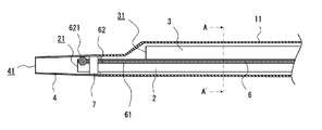
- FIG. FIG. 4 is an explanatory diagram showing the structure of the distal end portion of the catheter
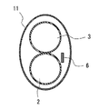
- 3 is a cross-sectional view taken along line A-A' in FIG. 2
- FIG. 4 is an explanatory diagram showing a modified example of the structure of the distal end portion of the catheter
- FIG. 1 is an explanatory diagram showing the structure of a catheter 10 according to this embodiment.
- 2 is an explanatory view showing the structure of the distal end portion (X portion in FIG. 1) of the catheter 10
- FIG. 3 is a cross-sectional view taken along line A-A' in FIG.
- the present invention is not limited only to the embodiments described below, and the embodiments are merely exemplifications described to explain the technical features of the present invention.
- the shapes and dimensions shown in each drawing are shown only for the purpose of facilitating the understanding of the contents of the present invention, and do not reflect the actual shapes and dimensions correctly.
- distal side means the direction along the axial direction of the shaft and the direction in which the catheter advances toward the treatment site.
- Base end side means a direction along the axial direction of the shaft, which is opposite to the above-mentioned distal end side.
- distal end refers to the distal end of any member or site
- base end refers to the proximal end of any member or site.
- distal end refers to a region of any member or site that includes the distal end and extends from the distal end toward the proximal side to the middle of the member, etc.
- proximal end refers to any part. In a member or region, it refers to a portion that includes the proximal end and extends from the proximal end toward the distal side to the middle of the member or the like.
- the catheter 10 includes a shaft 1 having a first lumen 2 and a second lumen 3 therein, a distal tip 4 at the distal end of the shaft 1, and a connector 5 at the proximal end of the shaft 1, as shown in FIG. installed.
- the catheter 10 also includes a core wire (reinforcing body) 6 inserted through the shaft 1 and extending along the first lumen 2 and the second lumen 3 .
- the shaft 1 is an elongated tubular member having along the axial direction a first lumen 2 and a second lumen 3 through which a guide wire is inserted. Designed accordingly.
- the shaft 1 includes a distal shaft 11 and a proximal shaft 12. Inside the distal shaft 11, a first lumen 2 and a second lumen 3 are arranged side by side (in the vertical direction in FIG. 1). , Only the second lumen 3 is provided extending from the distal shaft 11 inside the proximal shaft 12 .
- the distal shaft 11 and the proximal shaft 12 may be made of different materials, or may be made of the same material.
- the catheter 10 has two lumens (a first lumen 2 and a second lumen 3) through which guide wires are respectively inserted, and the first lumen 2 is an RX (rapid exchange) type guide.
- the wire lumen and the second lumen 3 are OTW (over-the-wire) type guide wire lumens, a double-lumen catheter for penetration will be described, but the catheter of the present invention is not limited to this. Instead, any catheter having at least one lumen therein can practice the present invention.
- the catheter of the present invention may be, for example, a single lumen catheter having only one lumen, a guiding catheter, a balloon catheter, or the like.
- the first lumen 2 has a distal opening 21 disposed inside a distal tip 4 attached to the distal end of the distal shaft 11 and connected to the distal tip 4,
- a proximal opening 22 is arranged in the peripheral wall of the distal shaft 11 near the proximal end and is open to the outside of the catheter 10 .
- the second lumen 3 has a distal opening 31 disposed near the distal end of the distal shaft 11 , and a proximal opening 32 connected to the connector 5 attached to the proximal end of the proximal shaft 12 . It is connected.
- Materials constituting the shaft 1, the first lumen 2, and the second lumen 3 are not particularly limited. preferably.
- resin materials such as polyamides, polyamide elastomers, polyolefins, polyesters, polyester elastomers, polyurethanes, silicones, and fluorine resins can be used.
- the tip 4 is a cylindrical (hollow) member connected to the tip of the shaft 1 (the tip side shaft 11).
- the distal tip 4 can be formed, for example, to have a tapered shape with a bore 41 penetrating along the axial direction and gradually decreasing in diameter toward the distal side.
- the material forming the distal tip 4 may be a material that is more flexible than the material forming the shaft 1.
- examples thereof include resin materials such as polyurethane, polyurethane elastomer, polyamide, and polyamide elastomer. .
- powder such as tungsten may be kneaded with these resin materials so that they can be visually recognized when irradiated with X-rays.
- the methods for joining the distal shaft 11 and the proximal shaft 12 and joining the distal tip 4 and the distal shaft 11 are not particularly limited as long as they do not impair the effects of the present invention. It is possible to adopt a method of welding by using a method of bonding by using an adhesive agent, or the like.
- the connector 5 is a member for gripping the catheter 1 by the operator, and is connected to the proximal end of the shaft 1.
- the connector 5 has a lumen (not shown) formed through it along the axial direction, and the distal end side opening of the lumen communicates with the second lumen 3 .
- the core wire 6 is a reinforcing body that is inserted through the interior of the shaft 1 and extends along the first lumen 2 and the second lumen 3, and is a bar-shaped member having a longitudinal shape as a whole.
- the core wire 6 extends over the entire length of the shaft 1 from the proximal end to the distal end, and as shown in FIG.
- the reason why the core wire 6 has a rectangular flat shape is to intentionally create a direction in which it is easy to bend.
- the core wire 6 is inserted so as to be parallel to an imaginary line (not shown) connecting the centers of the first lumen 2 and the second lumen 3 .
- the core wire 6 has a main body portion 61 as a first portion and a distal end portion 62 as a second portion located on the distal end side of the shaft 1 relative to the main body portion 61 . 1 is configured to be stronger than the direct or indirect coupling force of the body portion 61 to the shaft 1 .
- the material constituting the core wire 6 preferably has excellent rigidity from the viewpoint of preventing the core wire 6 itself from being cut and rotating the distal end of the catheter 10 reliably and accurately.
- examples of such materials include stainless steel such as SUS304, metal materials such as nickel-titanium alloys, and cobalt-chromium alloys.
- an impermeable marker 7 made of a material that hardly transmits X-rays is provided on the outer peripheral surface of the distal end portion of the first lumen 2.
- the impermeable marker 7 is a metal member having a tubular shape, and is arranged so as to surround the outer peripheral surface of the distal end portion of the first lumen 2 . Since the impermeable marker 7 is made of metal such as gold, platinum, tungsten, etc., when the catheter 10 is inserted into the living body, the position of the impermeable marker 7 can be imaged with X-rays from outside the body. be possible.
- a spherical engaging portion 621 that engages with the shaft 1 is formed at the tip of the tip portion 62 of the core wire 6 .
- the spherical engaging portion 621 is formed to have a larger cross-sectional shape than the flat portion of the core wire 6 other than the engaging portion 621 . That is, the distal end portion 62 includes the engaging portion 621 having a larger step area than the main body portion 61 . Further, by arranging the distal end portion 62 of the core wire inside the impermeable marker 7, that is, between the impermeable marker 7 and the outer peripheral surface of the first lumen 2, and crimping the impermeable marker 7, the core wire A tip 62 of 6 is fixed to the impermeable marker 7 . As a result, the tip of the core wire 6 is fixed to the shaft 1 .
- the breaking strength of the entire shaft 1 can be improved, and the tip of the shaft of the core wire 6 can be improved. Since the side end portion (tip portion 62) is strongly connected to the shaft 1, it is possible to prevent the core wire 6 from slipping out of the shaft when tension is applied in the longitudinal direction of the catheter 10.
- the breaking strength of the catheter 10 can be increased.
- the engaging portion 621 is provided at the distal end of the distal end portion 62 of the core wire 6, and the engaging portion 621 is located on the distal side of the impermeable marker 7, so that the core wire 6 and the impermeable marker 7 are arranged. Since it is sandwiched between the core wire 6 and the outer peripheral surface of the first lumen 2 , the engaging portion 621 is caught by the impermeable marker 7 , so that the core wire 6 is not easily pulled out of the shaft 1 .
- the core wire 6 has a flat shape at least on the distal end side of the shaft 1 in the direction in which the two lumens (the first lumen 2 and the second lumen 3) are arranged side by side (vertical direction in FIGS. 1 to 3). , it is possible to suppress an increase in bending rigidity at the tip of the shaft 1 .
- the core wire 6 has a body portion 61 that is a first portion and a tip portion 62 that is a second portion located on the distal end side of the shaft 1 relative to the body portion 61 .
- the direct or indirect coupling force of the tip portion 62 to the shaft 1 is stronger than the direct or indirect coupling force to the shaft 1 of the main body portion 61 .
- an engaging portion is not formed at the tip of the distal end portion 62 of the core wire 6 , but the distal end portion 62 of the core wire is arranged inside the impermeable marker 7 and the impermeable marker 7
- the tip 62 of the core wire 6 is fixed to the impermeable marker 7 by crimping. If the distal end portion 62 of the core wire 6 is fixed to the shaft 1 in this manner, it is possible to prevent the core wire 6 from slipping out of the shaft when tension is applied to the catheter 10 in the longitudinal direction.
- the distal end portion 62 of the core wire 6 is arranged outside the impermeable marker 7, and the distal end portion 62 of the core wire 6 is welded to the outer peripheral surface of the impermeable marker 7. 62 is attached to the opaque marker 7 . If the distal end portion 62 of the core wire 6 is fixed to the shaft 1 in this manner, it is possible to prevent the core wire 6 from slipping out of the shaft when tension is applied to the catheter 10 in the longitudinal direction.
- a spherical engaging portion 621 that engages with the shaft 1 is formed at the distal end portion 62 of the core wire 6, and the engaging portion 621 is positioned near the impermeable marker 7. there is Even if the distal end portion 62 of the core wire 6 is not fixed to the impermeable marker 7, the engaging portion 621 is shaped so as to be caught between the inner peripheral surface of the distal shaft 11 and the outer peripheral surface of the first lumen 2. With this, it is possible to fix the distal end portion 62 of the core wire 6 to the shaft 1 . If the distal end portion 62 of the core wire 6 is fixed to the shaft 1 in this manner, it is possible to prevent the core wire 6 from slipping out of the shaft when tension is applied to the catheter 10 in the longitudinal direction.
- the catheter according to the present invention has been described above based on the drawings, the present invention is not limited to the above embodiments, and various modifications are possible.
- the engaging portion 621 formed at the distal end portion 62 of the core wire 6 is not limited to being formed in a spherical shape.
- a block-like shape, a hook-like shape, or a shape that can be fixed inside the shaft to obtain an anchor effect may be used.
- the tip portion 62 of the core wire 6 may be welded to the inner peripheral surface of the opaque marker 7, or the tip portion 62 of the core wire 6 may be welded to the inner peripheral surface of the opaque marker 7.
- the tip portion 62 may be fixed to the inner or outer peripheral surface of the impermeable marker 7 by welding.
- the impermeable marker 7 may be crimped, or the tip 62 of the core wire 6 may be impermeable It may be fixed to the marker 7 using an adhesive or the like.
- the distal end portion of the core wire 6 is attached to the reinforcing layer provided in the lumen.
- the distal end portion 62 of the core wire 6 may be fixed inside the shaft 1 by fixing 62 .
- catheter 1 shaft 11 distal shaft 12 proximal shaft 2 first lumen 3 second lumen 4 distal tip 5 connector 6 core wire (reinforcement) 61 main body (first part) 62 tip (second part) 621 engaging portion 7 impermeable marker (cylindrical member)
Landscapes
- Health & Medical Sciences (AREA)
- Life Sciences & Earth Sciences (AREA)
- Biophysics (AREA)
- Pulmonology (AREA)
- Engineering & Computer Science (AREA)
- Anesthesiology (AREA)
- Biomedical Technology (AREA)
- Heart & Thoracic Surgery (AREA)
- Hematology (AREA)
- Animal Behavior & Ethology (AREA)
- General Health & Medical Sciences (AREA)
- Public Health (AREA)
- Veterinary Medicine (AREA)
- Media Introduction/Drainage Providing Device (AREA)
Priority Applications (3)
| Application Number | Priority Date | Filing Date | Title |
|---|---|---|---|
| EP22807463.9A EP4338780A4 (en) | 2021-05-12 | 2022-05-10 | Catheter |
| CN202280032144.8A CN117279687A (zh) | 2021-05-12 | 2022-05-10 | 导管 |
| US18/507,361 US20240075242A1 (en) | 2021-05-12 | 2023-11-13 | Catheter |
Applications Claiming Priority (2)
| Application Number | Priority Date | Filing Date | Title |
|---|---|---|---|
| JP2021-081278 | 2021-05-12 | ||
| JP2021081278A JP2022175116A (ja) | 2021-05-12 | 2021-05-12 | カテーテル |
Related Child Applications (1)
| Application Number | Title | Priority Date | Filing Date |
|---|---|---|---|
| US18/507,361 Continuation US20240075242A1 (en) | 2021-05-12 | 2023-11-13 | Catheter |
Publications (1)
| Publication Number | Publication Date |
|---|---|
| WO2022239763A1 true WO2022239763A1 (ja) | 2022-11-17 |
Family
ID=84029639
Family Applications (1)
| Application Number | Title | Priority Date | Filing Date |
|---|---|---|---|
| PCT/JP2022/019783 Ceased WO2022239763A1 (ja) | 2021-05-12 | 2022-05-10 | カテーテル |
Country Status (5)
| Country | Link |
|---|---|
| US (1) | US20240075242A1 (enExample) |
| EP (1) | EP4338780A4 (enExample) |
| JP (1) | JP2022175116A (enExample) |
| CN (1) | CN117279687A (enExample) |
| WO (1) | WO2022239763A1 (enExample) |
Cited By (2)
| Publication number | Priority date | Publication date | Assignee | Title |
|---|---|---|---|---|
| WO2024241379A1 (ja) * | 2023-05-19 | 2024-11-28 | 朝日インテック株式会社 | 医療デバイス、及び、医療デバイスの製造方法 |
| WO2024241378A1 (ja) * | 2023-05-19 | 2024-11-28 | 朝日インテック株式会社 | 医療デバイス、及び、医療デバイスの製造方法 |
Citations (4)
| Publication number | Priority date | Publication date | Assignee | Title |
|---|---|---|---|---|
| JP2008125897A (ja) | 2006-11-22 | 2008-06-05 | Kaneka Corp | カテーテル |
| JP2008264591A (ja) * | 1992-02-10 | 2008-11-06 | Scimed Life Systems Inc | ガイドワイヤー末端内腔及び中間部材を備える血管内カテーテル |
| JP2015062467A (ja) * | 2013-09-24 | 2015-04-09 | 朝日インテック株式会社 | バルーンカテーテル |
| JP2016165407A (ja) * | 2015-03-10 | 2016-09-15 | 朝日インテック株式会社 | バルーンカテーテル |
Family Cites Families (2)
| Publication number | Priority date | Publication date | Assignee | Title |
|---|---|---|---|---|
| JP5813842B2 (ja) * | 2014-09-22 | 2015-11-17 | 朝日インテック株式会社 | バルーンカテーテル |
| JP7352390B2 (ja) * | 2019-06-19 | 2023-09-28 | 朝日インテック株式会社 | カテーテル |
-
2021
- 2021-05-12 JP JP2021081278A patent/JP2022175116A/ja active Pending
-
2022
- 2022-05-10 WO PCT/JP2022/019783 patent/WO2022239763A1/ja not_active Ceased
- 2022-05-10 EP EP22807463.9A patent/EP4338780A4/en active Pending
- 2022-05-10 CN CN202280032144.8A patent/CN117279687A/zh not_active Withdrawn
-
2023
- 2023-11-13 US US18/507,361 patent/US20240075242A1/en active Pending
Patent Citations (4)
| Publication number | Priority date | Publication date | Assignee | Title |
|---|---|---|---|---|
| JP2008264591A (ja) * | 1992-02-10 | 2008-11-06 | Scimed Life Systems Inc | ガイドワイヤー末端内腔及び中間部材を備える血管内カテーテル |
| JP2008125897A (ja) | 2006-11-22 | 2008-06-05 | Kaneka Corp | カテーテル |
| JP2015062467A (ja) * | 2013-09-24 | 2015-04-09 | 朝日インテック株式会社 | バルーンカテーテル |
| JP2016165407A (ja) * | 2015-03-10 | 2016-09-15 | 朝日インテック株式会社 | バルーンカテーテル |
Non-Patent Citations (1)
| Title |
|---|
| See also references of EP4338780A4 |
Cited By (2)
| Publication number | Priority date | Publication date | Assignee | Title |
|---|---|---|---|---|
| WO2024241379A1 (ja) * | 2023-05-19 | 2024-11-28 | 朝日インテック株式会社 | 医療デバイス、及び、医療デバイスの製造方法 |
| WO2024241378A1 (ja) * | 2023-05-19 | 2024-11-28 | 朝日インテック株式会社 | 医療デバイス、及び、医療デバイスの製造方法 |
Also Published As
| Publication number | Publication date |
|---|---|
| CN117279687A (zh) | 2023-12-22 |
| JP2022175116A (ja) | 2022-11-25 |
| US20240075242A1 (en) | 2024-03-07 |
| EP4338780A4 (en) | 2025-05-07 |
| EP4338780A1 (en) | 2024-03-20 |
Similar Documents
| Publication | Publication Date | Title |
|---|---|---|
| US9017309B2 (en) | Thrombus-aspiration catheter | |
| US7785274B2 (en) | Guide wire | |
| JP4829684B2 (ja) | 医療用ガイドワイヤ | |
| CN111447967B (zh) | 医疗用管 | |
| US8092395B2 (en) | Guide wire for use in re-canalising a vascular occlusion in a human or animal subject | |
| US20070244413A1 (en) | Medical guidewire tip construction | |
| JP4028245B2 (ja) | ガイドワイヤ | |
| JP4751553B2 (ja) | ガイディングエイド | |
| EP2502645A1 (en) | Guidewire | |
| WO2022239763A1 (ja) | カテーテル | |
| US20160331943A1 (en) | Guide wire for use in re-canalising a vascular occlusion in a human or animal subject | |
| US11484687B2 (en) | Catheter | |
| CN114668955A (zh) | 导丝 | |
| US11234846B2 (en) | Guide catheter and delivery system | |
| JP2553401B2 (ja) | カテーテル | |
| JP2006271901A (ja) | コイル状造影マーカーとその製造方法、及びカテーテル | |
| CN111601632B (zh) | 导管 | |
| JP6864110B2 (ja) | ガイドワイヤ | |
| EP3995169A1 (en) | Catheter | |
| US9855407B2 (en) | Guide wire | |
| JP7290451B2 (ja) | ガイドワイヤ | |
| EP3659665A1 (en) | Balloon catheter | |
| US20230256203A1 (en) | Catheter | |
| JP2004065794A (ja) | ガイドワイヤ | |
| JP2013154070A (ja) | ガイドワイヤ |
Legal Events
| Date | Code | Title | Description |
|---|---|---|---|
| 121 | Ep: the epo has been informed by wipo that ep was designated in this application |
Ref document number: 22807463 Country of ref document: EP Kind code of ref document: A1 |
|
| WWE | Wipo information: entry into national phase |
Ref document number: 202280032144.8 Country of ref document: CN |
|
| WWE | Wipo information: entry into national phase |
Ref document number: 2022807463 Country of ref document: EP |
|
| NENP | Non-entry into the national phase |
Ref country code: DE |
|
| ENP | Entry into the national phase |
Ref document number: 2022807463 Country of ref document: EP Effective date: 20231212 |