WO2022239657A1 - 樹脂フィルムおよびその製造方法、ならびに金属化樹脂フィルム、プリント配線板 - Google Patents
樹脂フィルムおよびその製造方法、ならびに金属化樹脂フィルム、プリント配線板 Download PDFInfo
- Publication number
- WO2022239657A1 WO2022239657A1 PCT/JP2022/019095 JP2022019095W WO2022239657A1 WO 2022239657 A1 WO2022239657 A1 WO 2022239657A1 JP 2022019095 W JP2022019095 W JP 2022019095W WO 2022239657 A1 WO2022239657 A1 WO 2022239657A1
- Authority
- WO
- WIPO (PCT)
- Prior art keywords
- layer
- resin film
- metal oxide
- polyimide
- fumed metal
- Prior art date
- Legal status (The legal status is an assumption and is not a legal conclusion. Google has not performed a legal analysis and makes no representation as to the accuracy of the status listed.)
- Ceased
Links
Classifications
-
- B—PERFORMING OPERATIONS; TRANSPORTING
- B32—LAYERED PRODUCTS
- B32B—LAYERED PRODUCTS, i.e. PRODUCTS BUILT-UP OF STRATA OF FLAT OR NON-FLAT, e.g. CELLULAR OR HONEYCOMB, FORM
- B32B27/00—Layered products comprising a layer of synthetic resin
- B32B27/18—Layered products comprising a layer of synthetic resin characterised by the use of special additives
- B32B27/20—Layered products comprising a layer of synthetic resin characterised by the use of special additives using fillers, pigments, thixotroping agents
-
- B—PERFORMING OPERATIONS; TRANSPORTING
- B32—LAYERED PRODUCTS
- B32B—LAYERED PRODUCTS, i.e. PRODUCTS BUILT-UP OF STRATA OF FLAT OR NON-FLAT, e.g. CELLULAR OR HONEYCOMB, FORM
- B32B27/00—Layered products comprising a layer of synthetic resin
- B32B27/28—Layered products comprising a layer of synthetic resin comprising synthetic resins not wholly covered by any one of the sub-groups B32B27/30 - B32B27/42
- B32B27/281—Layered products comprising a layer of synthetic resin comprising synthetic resins not wholly covered by any one of the sub-groups B32B27/30 - B32B27/42 comprising polyimides
-
- B—PERFORMING OPERATIONS; TRANSPORTING
- B32—LAYERED PRODUCTS
- B32B—LAYERED PRODUCTS, i.e. PRODUCTS BUILT-UP OF STRATA OF FLAT OR NON-FLAT, e.g. CELLULAR OR HONEYCOMB, FORM
- B32B27/00—Layered products comprising a layer of synthetic resin
- B32B27/34—Layered products comprising a layer of synthetic resin comprising polyamides
-
- B—PERFORMING OPERATIONS; TRANSPORTING
- B32—LAYERED PRODUCTS
- B32B—LAYERED PRODUCTS, i.e. PRODUCTS BUILT-UP OF STRATA OF FLAT OR NON-FLAT, e.g. CELLULAR OR HONEYCOMB, FORM
- B32B37/00—Methods or apparatus for laminating, e.g. by curing or by ultrasonic bonding
- B32B37/14—Methods or apparatus for laminating, e.g. by curing or by ultrasonic bonding characterised by the properties of the layers
- B32B37/15—Methods or apparatus for laminating, e.g. by curing or by ultrasonic bonding characterised by the properties of the layers with at least one layer being manufactured and immediately laminated before reaching its stable state, e.g. in which a layer is extruded and laminated while in semi-molten state
-
- H—ELECTRICITY
- H05—ELECTRIC TECHNIQUES NOT OTHERWISE PROVIDED FOR
- H05K—PRINTED CIRCUITS; CASINGS OR CONSTRUCTIONAL DETAILS OF ELECTRIC APPARATUS; MANUFACTURE OF ASSEMBLAGES OF ELECTRICAL COMPONENTS
- H05K1/00—Printed circuits
- H05K1/02—Details
- H05K1/03—Use of materials for the substrate
-
- B—PERFORMING OPERATIONS; TRANSPORTING
- B32—LAYERED PRODUCTS
- B32B—LAYERED PRODUCTS, i.e. PRODUCTS BUILT-UP OF STRATA OF FLAT OR NON-FLAT, e.g. CELLULAR OR HONEYCOMB, FORM
- B32B2255/00—Coating on the layer surface
- B32B2255/20—Inorganic coating
- B32B2255/205—Metallic coating
-
- B—PERFORMING OPERATIONS; TRANSPORTING
- B32—LAYERED PRODUCTS
- B32B—LAYERED PRODUCTS, i.e. PRODUCTS BUILT-UP OF STRATA OF FLAT OR NON-FLAT, e.g. CELLULAR OR HONEYCOMB, FORM
- B32B2264/00—Composition or properties of particles which form a particulate layer or are present as additives
- B32B2264/10—Inorganic particles
-
- B—PERFORMING OPERATIONS; TRANSPORTING
- B32—LAYERED PRODUCTS
- B32B—LAYERED PRODUCTS, i.e. PRODUCTS BUILT-UP OF STRATA OF FLAT OR NON-FLAT, e.g. CELLULAR OR HONEYCOMB, FORM
- B32B2311/00—Metals, their alloys or their compounds
- B32B2311/12—Copper
-
- B—PERFORMING OPERATIONS; TRANSPORTING
- B32—LAYERED PRODUCTS
- B32B—LAYERED PRODUCTS, i.e. PRODUCTS BUILT-UP OF STRATA OF FLAT OR NON-FLAT, e.g. CELLULAR OR HONEYCOMB, FORM
- B32B2457/00—Electrical equipment
Definitions
- the present invention relates to a resin film and its manufacturing method, as well as a metallized resin film and a printed wiring board.
- a printed wiring board which has a circuit made of metal conductors on an insulating substrate, is widely used as a component that expresses the functions of electronic devices by mounting various electronic components on the printed wiring board.
- printed wiring boards are required to have narrower pitches of circuit wiring.
- (a) flexible printed wiring boards, (b) rigid-flex boards, (c) multilayer flexible boards, and (d) COFs (chip-on-films), etc. which can be folded and stored compactly inside electronic devices.
- COFs chip-on-films
- Patent Document 1 discloses a method of bonding a thin-film copper foil with a carrier to a polyimide sheet.
- Patent Document 2 discloses a method of forming a metal layer on a polyimide film using a physical vapor deposition method such as a vacuum vapor deposition method, a sputtering method, or an ion plating method.
- Patent Document 3 discloses an example in which a material containing a polyimide resin having a silicone structure and fumed silica is directly plated with copper by electroless plating.
- One embodiment of the present invention has been made in view of the above problems, and an object of the present invention is to provide a novel resin film having excellent solder resistance and adhesion, a method for producing the same, and a metallization obtained from the resin film. It is to provide a resin film and a printed wiring board.
- the layer A containing the polyimide resin and the fumed metal oxide is a heat-resistant resin film having a linear expansion coefficient of 20 ppm / ° C. or less, and at least one surface of the layer B. and the linear expansion coefficient of the polyimide resin is 30 ppm/°C or more and 100 ppm/°C or less.
- the layer A containing a polyimide resin and a fumed metal oxide is a heat-resistant resin film having a linear expansion coefficient of 20 ppm / ° C. or less.
- the layer A formed on one surface and having a linear expansion coefficient of the polyimide resin of 30 ppm/° C. or more and 100 ppm/° C. or less and containing a polyimide resin and a fumed metal oxide is a polyamide precursor of the polyimide resin. It is obtained by mixing an acid solution and a fumed metal oxide and imidating the obtained fumed metal oxide-dispersed polyamic acid solution.
- a material and method that exhibit excellent solder heat resistance and can be used for narrow-pitch circuit formation, specifically, excellent solder heat resistance and strong adhesion to a low-roughness surface It is possible to provide a resin film capable of forming an electroless plated layer showing
- Patent Document 1 irregularities are intentionally formed on the copper foil surface in order to ensure the adhesion between the insulating base material and the copper foil. Therefore, in Patent Document 1, although the thickness of the copper layer is usually thinner than the limit of the copper foil, there is an adverse effect on the circuit shape in the etching process, there is a limit to narrowing the pitch, and there is an adverse effect on the transmission characteristics. be.
- metals such as nickel, chromium, vanadium, titanium, and molybdenum are formed on the substrate surface by physical vapor deposition.
- metals such as nickel, chromium, and titanium cannot be completely removed only by etching with an etchant for copper during circuit formation. There is a problem that an etchant needs to be used and the process is complicated.
- Patent Document 3 discloses a resin film capable of forming an electroless plated layer on a low-roughness surface, there is room for improvement in terms of solder resistance and the like.
- the present invention has been made in view of the above problems, and an object of the present invention is to provide a novel resin film having excellent solder resistance and adhesion, a method for producing the same, and a metallized resin obtained from the resin film. It is to provide films and printed wiring boards.
- One embodiment of the present invention is, for example, a material (resin film) that exhibits excellent solder heat resistance and is compatible with narrow-pitch circuit formation, and a method therefor.
- An object of the present invention is to provide a resin film capable of forming an electroless plated layer exhibiting strong adhesion to a rough surface, and a method for producing the same.
- Another object of one embodiment of the present invention is to provide a metallized resin film and a printed wiring board obtained from the resin film.
- the layer A containing the polyimide resin and the fumed metal oxide is formed on at least one surface of the layer B, which is a heat-resistant resin film having a coefficient of linear expansion of 20 ppm/° C. or less. and the linear expansion coefficient of the polyimide resin is 30 ppm/°C or more and 100 ppm/°C or less.
- the resin film according to one embodiment of the present invention has the advantage of being excellent in solder resistance and adhesiveness due to the above configuration.
- adhesion is evaluated by peel strength (N/cm)
- solder resistance is evaluated by moisture absorption solder heat resistance.
- a layer A (also referred to as layer A) containing a polyimide resin and a fumed metal oxide will be described.
- Layer A of one embodiment of the present invention essentially comprises a polyimide resin and a fumed metal oxide.
- the adhesion between the resin film and the electroless metal plating layer especially the adhesion immediately after forming the electroless metal plating layer without heating, etc., can be greatly improved. It describes below about the way of thinking of the expression mechanism of adhesiveness.
- the electroless metal plating process consists of multiple independent chemical baths. These chemical baths are controlled under prescribed conditions (concentration, temperature, etc.), and the surface of the object to be plated is brought into contact with these chemicals for a prescribed period of time by means of immersion, showering, etc., and the surface undergoes chemical changes, such as causes a physical shape change.
- These chemical solutions contain various components, and their pH varies depending on the type of chemical solution, and some chemical solutions exhibit strong alkalinity and strong acidity.
- both the polyimide resin and the fumed metal oxide essential for one embodiment of the present invention interact with these chemicals, causing changes in chemical structure and physical shape, and electroless metal plating. It is thought that it has an effect on the improvement of adhesion with.
- fumed metal oxides and polyimide resins undergo chemical changes in alkaline environments.
- fumed metal oxides dissolve in alkaline environments to produce ionic metal oxides.
- a polyimide resin produces an ionic amic acid group through an imide ring cleavage reaction in an alkaline environment.
- ionic compounds such as ionic metal oxides and ionic amic acid groups
- react with metal ions in the electroless metal plating bath to A compound derived from the three components of "polyimide resin” can be formed at the interface between the polyimide resin and the metal plating. It is believed that the compound contributes to the adhesion, and as a result, the adhesion between the polyimide resin and the metal plating is enhanced.
- the dissolution rate of polyimide resin and fumed metal oxide in an alkaline environment is thought to be affected by the chemical structure and aggregate structure of polyimide resin, and the chemical structure and specific surface area of fumed metal oxide, respectively.
- Layer A containing the polyimide resin and fumed metal oxide of one embodiment of the present invention is exposed to an alkaline environment, dissolution occurs according to the respective dissolution rates of the polyimide resin and the fumed metal oxide.
- the layer A of one embodiment of the present invention has a structure in which a fumed metal oxide exists in a state of being buried in a polyimide resin phase.
- the surface of the layer A has the same particle size as the fumed metal oxide, depending on the dissolution rate of each of the polyimide resin and the fumed metal oxide in alkaline chemicals.
- the surface area of layer A can be increased as a result of the generation of fine irregularities. It is considered that the increase in the surface area of the layer A also contributes to the improvement in adhesion strength.
- the fumed metal oxide essential to one embodiment of the present invention has a structure in which primary particles are aggregated, and exists in a state of being buried in the polyimide resin phase.
- a part of certain structural units of the fumed metal oxide essential for one embodiment of the present invention is exposed to the surface and/or exists near the surface, and the other part exists in the bulk direction. It is thought that the two are strongly bound together and contribute to the improvement of the adhesion strength. That is, (i) the area of the interface where the compound derived from the three components of "fumed metal oxide" - "metal (e.g.
- a polyimide resin is characterized by containing an imide group in its chemical skeleton. It is believed that the imide group (functional group) in the polyimide resin interacts with the fumed metal oxide and the metal element (for example, copper element) to improve adhesion to the electroless metal plating layer. Therefore, it is essential that the polyimide resin contain an imide group in order to develop adhesion, which is an effect of one embodiment of the present invention.
- the coefficient of linear expansion of the polyimide resin used for layer A affects the adhesion, and specifically shows good adhesion when it is 30 ppm / ° C. or more. has been found independently and has led to an embodiment of the present invention.
- the linear expansion coefficient of the polyimide resin is the linear expansion coefficient in the plane direction when the polyimide resin used for the layer A is made into a film, and the degree of in-plane orientation in the layer A of the polyimide molecular chains is It is a reflection.
- a smaller linear expansion coefficient of the polyimide resin indicates that the polyimide molecular chains are oriented in the plane direction, and conversely, a larger coefficient indicates that the polyimide molecular chains are oriented in the thickness direction as well.
- the linear expansion coefficient of polyimide resin can be controlled by the type of monomer used.
- it is effective to use monomers having a rigid chemical structure and to increase their composition ratio.
- the polyimide molecular chains were oriented in the plane direction when processed (molded) into a film, and the molecular chains accumulated in the thickness direction. A state can be formed.
- the present inventors have independently found that if the coefficient of linear expansion of the polyimide resin of layer A is too small, the adhesion between the resin film and the electroless metal plating layer is reduced.
- the reason for this is not clear, but is presumed as follows.
- a polyimide obtained from a monomer mixture with a rigid chemical structure and a high composition ratio of the monomer is exposed to an alkaline chemical solution, the polyimide molecules near the surface are denatured into polyamic acid due to the cleavage reaction of the imide ring. , a state in which polyamic acid molecules oriented in the plane direction are deposited in the thickness direction is formed.
- the cohesive force between polyamic acid molecular chains is weaker than the cohesive force between polyimide molecular chains. Therefore, when an electroless metal plating layer (film) was formed on the surface of the film obtained by exposing the polyimide to an alkaline chemical solution, and the adhesion was evaluated, layer breakage occurred between polyamic acid molecular chains with weak cohesive force. It is presumed that the adhesion strength between the film and the plating layer (membrane) tends to be low as a result of peeling at the interface. It should be noted that the present invention is by no means limited to such speculation.
- the present inventors have found that the adhesion between the resin film and the electroless metal plating layer is enhanced when the linear expansion coefficient of the polyimide resin of the layer A is large (for example, 30 ppm / ° C. or more). found on its own. The reason for this is not clear, but is presumed as follows.
- the polyimide obtained from a monomer mixture that uses a monomer with a flexible chemical structure and a high composition ratio of the monomer is exposed to an alkaline chemical solution, the polyimide molecules near the surface are modified into polyamic acid due to the cleavage reaction of the imide ring.
- the polyimide has a small linear expansion coefficient and in-plane molecular orientation as described above. It is presumed that there is no layered separation between polyamic acid molecular chains as in the case of advanced polyimide, and as a result, the adhesion strength to electroless metal plating tends to increase. It should be noted that the present invention is by no means limited to such speculation.
- the polyimide resin used for the layer A tends to be randomly oriented more than the polyimide resin with advanced in-plane molecular orientation from the viewpoint that the cohesive force of the polyimide resin itself is not reduced even if the polyimide resin is exposed to an alkaline chemical solution. It is preferable to use a polyimide resin that has a certain property, that is, a polyimide resin that tends to have isotropic molecular orientation.
- polyimide resin there is a correlation between the degree of in-plane molecular orientation and the coefficient of linear expansion.
- the polyimide resin when the in-plane molecular orientation is highly advanced, and as a result the peel strength between the plane-oriented polymer chains is weakened, the coefficient of linear expansion is less than 30 ppm/°C.
- the polyimide resin used for the layer A has a tendency to be oriented not only in the surface direction but also in the thickness direction, that is, a random orientation tendency, thereby improving the adhesion to the electroless metal plating.
- the linear expansion coefficient of the polyimide resin is preferably 30 ppm/° C.
- the linear expansion coefficient of the polyimide resin of layer A is preferably 100 ppm/° C. or less, more preferably 90 ppm/° C. or less, more preferably 80 ppm/° C. or less, and more preferably 75 ppm/° C. or less. more preferably 70 ppm/°C or less, still more preferably 65 ppm/°C or less, and particularly preferably 60 ppm/°C or less.
- the coefficient of linear expansion of the polyimide resin used for layer A is preferably 30 ppm/°C or more, more preferably greater than 30 ppm/°C. As the linear expansion coefficient of the polyimide resin increases, the polyimide resin tends to exhibit thermoplasticity. Thermoplastic resin softens when it reaches a certain temperature, and there is an advantage that it can be processed by using this fact, for example, it can be thermocompressed with copper foil. From the viewpoint of improving adhesion to electroless metal plating, which is the object of one embodiment of the present invention, thermoplasticity is not an essential requirement.
- the polyimide resin can withstand the temperature of high temperature processes during its processing and the high temperature when parts are mounted.
- the polyimide resin used for the layer A preferably has a high glass transition temperature and a high elastic modulus at high temperatures, and there is no particular problem if the glass transition temperature is too high.
- the glass transition temperature of the polyimide resin which is an index of heat resistance, is preferably as high as possible, for example, preferably 180° C. or higher, more preferably 230° C. or higher.
- the polyimide resin used for the layer A has a certain or more elastic modulus even near the melting point of solder.
- the polyimide resin contained in Layer A preferably has a storage modulus at 300° C. of 0.2 ⁇ 10 8 Pa or more, more preferably 0.5 ⁇ 10 8 Pa or more, and 0 It is more preferably 0.8 ⁇ 10 8 Pa or more, and particularly preferably 1.0 ⁇ 10 8 Pa or more.
- a soluble polyimide that is soluble in an organic solvent As the polyimide resin for the layer A to produce the resin film of one embodiment of the present invention. Specifically, a soluble polyimide is dissolved in an organic solvent, and a fumed metal oxide is further dispersed in the resulting solution to obtain a dispersion. can be dried to obtain the resin film of one embodiment of the present invention.
- the layer A is used to prevent problems such as dissolution of the resin in the process using an organic solvent in the manufacturing process and mounting process of the printed circuit board.
- the polyimide resin used is preferably insoluble.
- the polyimide resin of the layer A and the layer B which is a heat-resistant resin film, are firmly adhered to each other.
- the precursor of the polyimide resin of layer A (or a solution containing the precursor) is brought into contact with layer B, and then the precursor is imidized. is preferred.
- the polyimide resin used for layer A can achieve one embodiment of the present invention whether it is soluble or insoluble, but is preferably insoluble.
- the polyimide resin contained in layer A is preferably a non-soluble polyimide resin.
- the polyimide resin is insoluble means that the polyimide resin does not dissolve in organic solvents generally used for industrial purposes. Specifically, the polyimide resin preferably does not dissolve in an organic solvent at 20° C. to 30° C. in an amount of 10% by weight or more, and more preferably does not dissolve in an amount of 5% by weight or more.
- organic solvents examples include alcohol solvents such as methanol, ethanol and propanol; ketone solvents such as acetone and methyl ethyl ketone; aromatic solvents such as toluene, xylene, cresol and benzene; Ether-based solvents; aprotic polar solvents such as N-methylpyrrolidone, N,N-dimethylformamide, N,N-dimethylacetamide, dimethylsulfoxide, and acetonitrile, but not limited thereto.
- alcohol solvents such as methanol, ethanol and propanol
- ketone solvents such as acetone and methyl ethyl ketone
- aromatic solvents such as toluene, xylene, cresol and benzene
- Ether-based solvents examples include aprotic polar solvents such as N-methylpyrrolidone, N,N-dimethylformamide, N,N-dimethylacetamide, dimethyl
- the polyimide resin used for the layer A must have a coefficient of linear expansion of 30 ppm/°C or more and 100 ppm/°C or less. It is preferable to appropriately control the physical properties of the polyimide resin, such as the glass transition temperature, the storage modulus at high temperatures, and the solubility in organic solvents. Selection of raw materials to be used is one means of controlling these physical properties within appropriate ranges. As raw material monomers for polyimide resins, there are monomers with flexible skeletons and monomers with rigid skeletons, and it is possible to realize desired physical properties by appropriately selecting these and adjusting the compounding ratio. Become.
- Diamines having a flexible skeleton include 4,4'-oxydianiline, 3,3'-oxydianiline, 3,4'-oxydianiline, bis ⁇ 4-(4-aminophenoxy)phenyl ⁇ sulfone, 2,2′-bis ⁇ 4-(4-aminophenoxy)phenyl ⁇ propane, bis ⁇ 4-(3-aminophenoxy)phenyl ⁇ sulfone, 4,4′-diaminodiphenyl ether, 3,4′-diaminodiphenyl ether, 3 , 3′-diaminodiphenyl ether, 4,4′-diaminodiphenylthioether, 3,4′-diaminodiphenylthioether, 3,3′-diaminodiphenylthioether, 4,4′-diaminodiphenylmethane, 3,4′-diaminodiphenylmethane, 3,3'-diaminodipheny
- diamines having a rigid skeleton include 1,4-diaminobenzene (p-phenylenediamine), 1,3-diaminobenzene, 1,2-diaminobenzene, benzidine, 3,3'-dichlorobenzidine, 3, 3'-dimethylbenzidine, 2,2'-dimethylbenzidine, 3,3'-dimethoxybenzidine, 2,2'-dimethoxybenzidine, 3,3'-dihydroxy-4,4'-diaminobiphenyl, 2,2'- bis(trifluoromethyl)benzidine, 1,5-diaminonaphthalene, 4,4'-diaminobenzanilide, 3,4'-diaminobenzanilide, 3,3'-diaminobenzanilide, and the like.
- 1,4-diaminobenzene p-phenylenediamine
- 1,3-diaminobenzene 1,2-diaminobenzene
- 4,4'-oxydianiline, 4,4'-diaminodiphenylpropane, 4,4'-diamino as the diamine having a flexible skeleton from the viewpoint of thermal property control and industrial availability.
- 1,3-bis(4-aminophenoxy)benzene and 2,2′-bis ⁇ 4-(4-aminophenoxy)phenyl ⁇ propane More than one species can be preferably used.
- diamines having a rigid skeleton 1,4-diaminobenzene (p-phenylenediamine), 1, 1, 4-diaminobenzene (p-phenylenediamine), 1, One or more selected from the group consisting of 3-diaminobenzene and 2,2'-dimethylbenzidine can be preferably used.
- 1,4-diaminobenzene p-phenylenediamine
- 2,2'-dimethylbenzidine can be preferably used.
- One of these diamines may be used alone, or two or more of them may be mixed (combined) and used.
- Tetracarboxylic dianhydrides having a flexible skeleton include 3,3′,4,4′-biphenyltetracarboxylic dianhydride, 2,3,3′,4′-biphenyltetracarboxylic dianhydride, 3,3',4,4'-benzophenonetetracarboxylic dianhydride, 3,4'-oxydiphthalic anhydride, 4,4'-oxydiphthalic anhydride, 3,3',4,4'-diphenylsulfone Tetracarboxylic dianhydride, 4,4'-(hexafluoroisopropylidene) phthalic anhydride, 4,4'-(4,4'-isopropylidene diphenoxy) diphthalic anhydride, 2,2-bis( 3,4-dicarboxyphenyl)propane dianhydride, bis(3,4-dicarboxyphenyl)propane dianhydride, 1,1-bis(2,3-dicarboxyphen
- tetracarboxylic dianhydrides having a rigid skeleton include pyromellitic dianhydride, 2,3,6,7-naphthalenetetracarboxylic dianhydride, and 1,2,5,6-naphthalenetetracarboxylic acid. acid dianhydride, 3,4,9,10-perylenetetracarboxylic dianhydride, and the like.
- 3,3',4,4'-biphenyltetracarboxylic dianhydride 2 , 3,3′,4′-biphenyltetracarboxylic dianhydride, 3,3′,4,4′-benzophenonetetracarboxylic dianhydride and 4,4′-oxydiphthalic anhydride.
- 3,3',4,4'-biphenyltetracarboxylic dianhydride 2
- 3,3′,4′-biphenyltetracarboxylic dianhydride 3,3′,4,4′-benzophenonetetracarboxylic dianhydride
- 4,4′-oxydiphthalic anhydride 4,4′-oxydiphthalic anhydride.
- One or more of these can be preferably used.
- 3,3′,4,4′-biphenyltetracarboxylic dianhydride is more preferable, and various physical properties desired in a preferred embodiment of the present invention, namely, adhesion to an electroless plated film, It can be effectively used to develop the elastic modulus, the glass transition temperature, the linear expansion coefficient of the polyimide resin, and the like in a well-balanced manner.
- pyromellitic dianhydride is preferably used because it exhibits the effect of hardening the polymer chain with a relatively small amount and is easily available industrially. obtain.
- These tetracarboxylic dianhydrides may be used in combination of two or more.
- the inventors of the present invention have empirically obtained a tendency to show good adhesion by using a combination of acid dianhydrides and diamines that reduce the polarization of the imide ring of the polyimide resin. be. Specifically, at least one of 4,4'-oxydiphthalic dianhydride and 3,3',4,4'-biphenyltetracarboxylic dianhydride as the acid dianhydride, and 2,2'-bis as the diamine. A combination with (trifluoromethyl)benzidine is effective.
- a preferred combination of diamine and acid dianhydride is not particularly limited. 2,2′-bis(trifluoromethyl)benzidine, 4,4′-oxydianiline, 1,3-bis(4-aminophenoxy)benzene and 2,2′-bis ⁇ 4-(4-amino) as diamines phenoxy)phenyl ⁇ propane, and 4,4'-oxydiphthalic dianhydride and 3,3',4,4'-biphenyltetracarboxylic dianhydride as acid dianhydrides. It is preferable to select a combination with at least one of and further combine a fumed metal oxide in an appropriate type and blending amount.
- the adhesion to the electroless metal plating layer of one embodiment of the present invention can be improved, and in particular, the initial state after the formation of the electroless metal plating layer can be greatly improved, which is preferable.
- Polyamic acid which is a precursor of the polyimide of layer A, is obtained by mixing the diamine and acid dianhydride in an organic solvent so as to be substantially equimolar or substantially equimolar and reacting them.
- organic solvent Any organic solvent can be used as long as it can dissolve polyamic acid.
- amide solvents such as N,N-dimethylformamide, N,N-dimethylacetamide, N-methyl-2-pyrrolidone, etc. are preferred, and at least N,N-dimethylformamide and N,N-dimethylacetamide One can be used particularly preferably.
- the solid content concentration of the polyamic acid is not particularly limited, and if it is within the range of 5% by weight to 35% by weight, a polyamic acid having sufficient mechanical strength when made into a polyimide can be obtained.
- the order of addition of the raw materials diamine and acid dianhydride is also not particularly limited. It is possible to control the properties of the resulting polyimide not only by controlling the chemical structures of the raw materials diamine and acid dianhydride, but also by controlling the order of their addition.
- the polyimide structure obtained by combining the two has low durability against desmear liquid, so 1,4-diaminobenzene and pyromellitic acid It is preferable to adjust the order of addition of the dianhydride so as not to form a structure in which the two are directly bonded.
- Layer A may contain a resin other than the polyimide resin described above as a resin component. It is preferable that the content ratio of the polyimide resin in the resin component contained in the layer A is large.
- the polyimide resin in 100% by weight of the resin component contained in layer A, is preferably 50% by weight or more, more preferably 60% by weight or more, and more preferably 70% by weight or more. , more preferably 80% by weight or more, still more preferably 90% by weight or more, and most preferably 95% by weight or more. It is most preferable that the polyimide resin is 100% by weight in 100% by weight of the resin component contained in the layer A. In other words, it is most preferable that the layer A contains only the polyimide resin as the resin component.
- Fumed metal oxides used in one embodiment of the present invention are metal oxides based on silica, alumina, titania, or the like.
- the fumed metal oxide used in one embodiment of the present invention is preferably a metal oxide obtained by vapor phase synthesis.
- the resulting fumed metal oxide is characterized in that the structural unit is a structure in which primary particles aggregate.
- the fumed metal oxide has a structural unit of aggregated primary particles (for example, it has an aggregated structure like a cluster of grapes).
- a fumed metal oxide is mixed with a polyimide resin to form Layer A of one embodiment of the present invention.
- layer A has (i) a structural unit of a fumed metal oxide embedded in a polyimide resin with low voids, and (ii) the structural unit is on the surface of layer A. and/or exists from the vicinity of the surface to the bulk direction, and (iii) the structural unit is evenly present and dispersed in the layer A.
- a state is one embodiment of the present invention. We believe that it is effective for developing adhesion, which is the purpose of the morphology.
- spherical or amorphous metal oxide particles in which primary particles exist independently (for example, colloidal metal oxide particles) Silica) is not preferred because it tends to have weaker binding force with the polyimide resin than fumed metal oxides.
- the layer A may further contain spherical or amorphous metal oxide particles in which the primary particles are independently present. It is preferable that the amount of the metal oxide particles in the layer A is as small as possible.
- the amount of the metal oxide particles is preferably less than 10 parts by weight, more preferably 5 parts by weight or less, with respect to 100 parts by weight of the precursor of the polyimide resin, and 1 part by weight. or less, more preferably 0.5 parts by weight or less, and particularly preferably 0.1 parts by weight or less.
- the porosity in the layer A tends to increase when the blending ratio of the fumed metal oxide is increased.
- the porosity in the layer A is not too high, the binding force between the polyimide resin and the fumed metal oxide does not decrease, and the strength of the layer A itself tends to be good, resulting in electroless metal plating.
- the adhesion between the layer A and the layer B tends to be improved. Therefore, in blending the polyimide resin and the fumed metal oxide, it is preferable that the blending ratio of the fumed metal oxide is not too high.
- the porosity tends to decrease as the blending ratio of the fumed metal oxide decreases.
- the porosity in the layer A is not too low, it is preferable because sufficient adhesion to the electroless metal plating is likely to be exhibited. This is because the ratio of fumed metal oxide is not too low, so that the amount of compounds derived from the three components of "fumed metal oxide” - "metal (eg copper)" - “polyimide resin” is sufficient. I think that is the reason. It should be noted that the present invention is not limited to such speculation.
- the compounding ratio of the polyimide resin and the fumed metal oxide within an appropriate range in order to develop good adhesion.
- the primary particle size of the fumed metal oxide is small. It is 5 nm or more and 50 nm or less, more preferably 10 nm or more and 20 nm or less.
- the specific surface area of the fumed metal oxide is also a physical property value that expresses the primary particle size, and the larger the primary particle size, the smaller the specific surface area.
- the specific surface area of the fumed metal oxide is preferably 30 square meters/gram or more and 400 square meters/gram or less, more preferably 100 square meters/gram or more and 250 square meters/gram or less.
- a fumed metal oxide is a structure in which the primary particle diameter aggregates, and the apparent specific gravity can be used as an index representing the state of the structure of the fumed metal oxide.
- a low apparent specific gravity of the fumed metal oxide indicates that the structure of the fumed metal oxide has a bulky structure and large voids.
- a high apparent specific gravity of the fumed metal oxide indicates that the structure of the fumed metal oxide has a less bulky structure and smaller voids.
- a layer A with a small porosity can be produced by filling the voids of the structure in which the primary particle size of the fumed metal oxide aggregates with the polyimide resin component.
- the bonding strength between the polyimide resin and the fumed metal oxide does not decrease, and the strength of the layer A itself tends to be good, and as a result, the adhesion to the electroless metal plating tends to be good, And the adhesion between layer A and layer B also tends to be good. Therefore, in blending the polyimide resin and the fumed metal oxide, it is preferable that the blending ratio of the fumed metal oxide is not too high. Conversely, when the ratio of the fumed metal oxide is not too low, sufficient adhesion to the electroless metal plating tends to be exhibited. In other words, when blending the polyimide resin and the fumed metal oxide, blending the fumed metal oxide in the vicinity of the upper limit of the blending amount is effective for exhibiting good adhesion.
- the upper limit of the amount of fumed metal oxide compounded with respect to a certain amount of polyimide resin for making layer A with a small porosity varies depending on the apparent specific gravity of the fumed metal oxide and the type of surface treatment. That is, the adhesion can be further improved by adjusting the blending amount of the fumed metal oxide with respect to a certain amount of polyimide resin according to the apparent specific gravity of the fumed metal oxide and the type of surface treatment.
- the apparent specific gravity of the fumed metal oxide is preferably 20 grams/liter or more and 250 grams/liter or less, more preferably 20 grams/liter or more and 220 grams/liter or less.
- the apparent specific gravity of the fumed metal oxide is more preferably greater than 50 grams/liter and 250 grams/liter or less, more preferably 60 grams/liter or more and 250 grams/liter or less, and more preferably 70 grams/liter. It is more preferably 70 grams/liter or more and 220 grams/liter or less, more preferably 70 grams/liter or more and 220 grams/liter or less.
- the apparent specific gravity of the fumed metal oxide can be changed by modifying the structure of the fumed metal oxide by mechanically applying stress such as shear to the fumed metal oxide.
- fumed metal oxides Various surface treatments are possible for fumed metal oxides.
- Surface conditions of fumed metal oxides include silanol (untreated), dimethylsilyl, octylsilyl, trimethylsilyl, dimethylsiloxane, dimethylpolysiloxane, aminoalkylsilyl, methacrylsilyl, etc., all of which are industrially available.
- the surface treatment species of the fumed metal oxide and the polarity of the polyimide resin component are close to each other, the upper limit of the compounding amount of the fumed metal oxide tends to be high.
- the surface of the fumed metal oxide is not treated, the wettability with the alkaline chemical solution during the electroless metal plating process is too good, so the amount of the fumed metal oxide dissolved increases, and the surface roughness of the layer A increases. tend to become Therefore, it is preferable that the surface of the fumed metal oxide is subjected to a suitable hydrophobic treatment.
- the apparent specific gravity of the fumed metal oxide can be measured according to ISO787/XI.
- Fumed metal oxides that can be preferably used in one embodiment of the present invention are shown below, but are not limited to these. Fumed metal oxides that meet various property requirements, including apparent specific gravity, are more suitable for use in one embodiment of the present invention. Various grades of fumed metal oxides with different primary particle sizes, specific surface areas, surface treatment types, apparent specific gravities, and metal oxide types are available from Nippon Aerosil Co., Ltd., Asahi Kasei Wacker Silicone Co., Ltd., and Cabot Corporation, and can be preferably used. . The fumed metal oxide produced by Nippon Aerosil Co., Ltd. will be described below in detail.
- Aerosil R972, R972CF, R972V, etc. which are substantially the same except for the apparent specific gravity, can preferably be used, and among these, R972 (50 g/liter), which has a higher apparent specific gravity, can be used more preferably.
- Aerosil R974, R9200, VP RS920, etc. which are equivalent except for their apparent specific gravities, can preferably be used. liter or more and 120 g/liter or less) can be used more preferably.
- Aerosil NX130, RY200S, and R976 are fumed metal oxides manufactured by Nippon Aerosil Co., Ltd., which have a relatively low apparent specific gravity of 70 g/liter or less, which is one of the preferable physical properties of one embodiment of the present invention.
- NAX50, NX90G, NX90S, RX200, RX300, R812, R812S, etc. can be preferably used. Fumed metal oxides manufactured by Nippon Aerosil Co., Ltd.
- Aerosil 200V Aerosil 200V
- AEROIDE TiO2 P90 AEROIDE TiO2 NKT90
- OX50 RY50
- RY51 AEROIDE TiO2 P25, R8200, and RM50.
- RX50, AEROIDE TiO2 T805, R7200, etc. are also preferably usable.
- Aerosil VP RS920 has been sold under the name of "Aerosil E9200" since November 2021.
- "Aerosil” or “AEROSIL” is a registered trademark of Evonik Operations GmbH.
- As the fumed metal oxide a fumed metal oxide synthesized by vapor phase synthesis and having a structure in which primary particle diameters are aggregated can be preferably used.
- fumed silica such as Aerosil R972, 972V, NX130, R9200, VP RS920, R974, R976, R8200 has a good surface shape of layer A formed by dissolution in an alkaline environment. , the surface roughness is also within an appropriate range.
- Layer A containing a polyimide resin and a fumed metal oxide is preferably an imidized product of a mixture of a precursor of the polyimide resin and a fumed metal oxide (for example, a fumed metal oxide-dispersed polyamic acid solution described later). .
- the fumed metal oxide is mixed with a polyamic acid solution that is a precursor of the polyimide resin that constitutes Layer A, (a) the resulting mixture is applied to the heat-resistant film of Layer B, and Layer B is formed.
- the resin film of one embodiment of the present invention is obtained by co-extrusion with the resin precursor solution of layer B or the resin solution of layer B, etc., drying the obtained extrudate, and imidizing the mixture. be able to.
- the amount of the fumed metal oxide compounded is preferably 10 parts by weight or more and 130 parts by weight or less with respect to 100 parts by weight of the polyimide resin precursor of the layer A.
- the preferred number of parts of the fumed metal oxide to be added to the polyimide precursor (polyimide resin) of layer A can be adjusted to some extent by the apparent specific gravity of the fumed metal oxide, but there is also the influence of the surface treatment of the fumed metal oxide. , I can't say for certain.
- the preferred number of parts of the fumed metal oxide to be blended is described.
- the number of parts of the fumed metal oxide (relative to the solid content of the polyimide (precursor) resin) is 100 parts by weight of the precursor of the polyimide resin. 15 parts by weight or more and 80 parts by weight or less, more preferably 20 parts by weight or more and 60 parts by weight or less.
- the blending number of the fumed metal oxide (relative to the polyimide (precursor) resin solid content of 100 parts by weight) is 10 parts by weight or more and 130 parts by weight. parts by weight or less, more preferably 15 to 120 parts by weight, and even more preferably 20 to 100 parts by weight.
- the preferred number of parts to be blended varies depending on the apparent specific gravity of the fumed metal oxide, and the higher the apparent specific gravity of the fumed metal oxide, the greater the amount of the fumed metal oxide to be blended, and the more preferable blended amount.
- Tend. By blending the fumed metal oxide in the above range with respect to 100 parts by weight of the precursor of the polyimide resin, it is possible to exhibit a better adhesion strength, especially in the initial state after the electroless plating film is formed. It is possible to make it adhere to. It is also possible to mix (combine) multiple types of fumed metal oxides with different primary particle sizes, specific surface areas, surface treatment types, apparent specific gravities, metal oxide types, and the like.
- a polyimide resin precursor solution for Layer A and a fumed metal oxide are mixed and dispersed to form a fumed metal oxide dispersed polyamic acid solution (hereinafter Layer A dispersion). (sometimes referred to as .) is preferably obtained.
- the layer A can be obtained by imidizing the layer A dispersion.
- layer A is preferably an imidized mixture of a polyimide resin precursor and the fumed metal oxide. This configuration has the advantage that the adhesion between the layer A and the layer B is enhanced.
- the procedure for obtaining the layer A dispersion will be specifically described below, but one embodiment of the present invention is not limited thereto.
- An organic solvent is added to the fumed metal oxide, and the fumed metal oxide is dispersed in the organic solvent to the structural units of the structure in which the primary particles are aggregated.
- Dispersion methods include dispersers, homogenizers, planetary mixers, bead mills, rotation/revolution mixers, rolls, kneaders, high-pressure dispersers, ultrasonic waves, and resolvers. As long as the effect of one embodiment of the present invention can be obtained, the fumed metal oxide does not have to be dispersed to the above structural units in the organic solvent.
- the fumed metal oxide when the fumed metal oxide can be dispersed to the structural unit, the fumed metal oxide does not exist as a lump in the layer A, and in that case, the surface roughness of the layer A is small, which is one of the aspects of the present invention. This is preferable because it is advantageous for the formability of fine wiring, which is the aim of the embodiment. It is also possible to disperse and pulverize the fumed metal oxide under conditions that make the structural unit smaller.
- the organic solvent a solvent used for polyamic acid polymerization can be used, and amide solvents such as N,N-dimethylformamide, N,N-dimethylacetamide, and N-methyl-2-pyrrolidone are preferably used. is not limited to
- the concentration of the finally obtained layer A dispersion is not particularly limited, it is preferable to make the concentration and viscosity suitable for the next process.
- An organic solvent can be appropriately used for adjusting the concentration and viscosity of the layer A dispersion.
- amines for the purpose of imparting adhesion to the layer B, a dehydrating agent for imidizing polyamic acid, a catalyst, etc. may be further added to the layer A dispersion or the like.
- a filler can also be added to the layer A dispersion for the purpose of improving various properties of the film such as slidability, thermal conductivity, electrical conductivity, corona resistance, and loop stiffness.
- Any filler may be used, but preferred examples include silica, titanium oxide, alumina, silicon nitride, boron nitride, calcium hydrogen phosphate, calcium phosphate, and mica.
- Thermosetting resins such as epoxy resins and phenoxy resins, and thermoplastic resins such as polyether ketones and polyether ether ketones may also be used as long as the properties of the resulting resin layer as a whole are not impaired.
- a method for adding these resins if they are soluble in a solvent, a method of adding them to the polyamic acid can be mentioned. If the polyimide is also soluble, it may be added to the polyimide solution.
- a layer A dispersion can be obtained by the above procedure.
- Layer A is formed on one side or both sides of layer B, which is a heat-resistant resin film of one embodiment of the present invention.
- the coefficient of linear expansion of layer B is preferably 20 ppm/° C. or less.
- the resin composition of layer B is not particularly limited, a liquid crystal polymer film, a resin film containing reinforcing fibers, a resin film containing an inorganic filler, polyimide, and the like are preferable.
- Layer B is more preferably a film containing polyimide (or made of polyimide) from the viewpoint of heat resistance, flexibility, heat resistance, etc., and contains non-thermoplastic polyimide (or consists of non-thermoplastic polyimide ) film is more preferred.
- the linear expansion coefficient of a polyimide resin film can be controlled by the type of monomer used.
- a monomer having a rigid chemical structure and increase its composition ratio By using a monomer with a rigid chemical structure and increasing its composition ratio, the polyimide molecular chains are oriented in the plane direction when molded (processed) into a film, and the molecular chains are deposited in the thickness direction. can be formed.
- a monomer having a flexible chemical structure and increase its composition ratio in order to increase the linear expansion coefficient of the polyimide resin film.
- the polyimide molecular chains are oriented not only in the plane direction but also in the thickness direction when formed into a film, that is, randomly oriented. tend to show
- the diamine used in the production of the non-thermoplastic polyimide film is not particularly limited, but the linear expansion coefficient of the finally obtained polyimide film is 20 ppm / ° C. or less. need to be Therefore, in the production of a non-thermoplastic polyimide film, it is preferable to use an appropriate combination of a rigid-structured diamine and a flexible-structured diamine according to the structure of the acid dianhydride.
- the acid dianhydride used in the production of the non-thermoplastic polyimide film is not particularly limited, but the linear expansion coefficient of the finally obtained polyimide is 20 ppm / °C or less. Therefore, in the production of the non-thermoplastic polyimide film, it is preferable to use an appropriate combination of a rigid-structure acid dianhydride and a flexible-structure acid dianhydride according to the structure of the diamine.
- Specific acid dianhydrides having a rigid structure that are suitably used for the production of non-thermoplastic polyimide films include 3,3',4,4'-biphenyltetracarboxylic dianhydride and pyromellitic dianhydride.
- Acid dianhydrides having a flexible structure which are preferably used for the production of non-thermoplastic polyimide films, are 3,3′,4,4′-benzophenonetetracarboxylic dianhydride and 4,4′-oxydiphthalic dianhydride. etc.
- acid dianhydrides listed when explaining the polyimide resin of Layer A it is also possible to appropriately use the acid dianhydrides listed when explaining the polyimide resin of Layer A.
- Polyamic acid which is a precursor of polyimide, is obtained by mixing the diamine and acid dianhydride in an organic solvent so that they are substantially equimolar or approximately equimolar, and reacting them. Any organic solvent can be used as long as it can dissolve polyamic acid.
- organic solvent amide solvents such as N,N-dimethylformamide, N,N-dimethylacetamide, N-methyl-2-pyrrolidone, etc. are preferred, and at least N,N-dimethylformamide and N,N-dimethylacetamide One can be used particularly preferably.
- the solid content concentration of the polyamic acid is not particularly limited, and if it is within the range of 5% by weight to 35% by weight, a polyamic acid having sufficient mechanical strength when made into a polyimide can be obtained.
- the order of addition of the raw materials diamine and acid dianhydride is also not particularly limited. It is possible to control the properties of the resulting polyimide not only by controlling the chemical structures of the raw materials diamine and acid dianhydride, but also by controlling the order of their addition.
- a filler can also be added to the polyamic acid for the purpose of improving various properties of the film such as slidability, thermal conductivity, electrical conductivity, corona resistance, and loop stiffness.
- Any filler may be used, but preferred examples include silica, titanium oxide, alumina, silicon nitride, boron nitride, calcium hydrogen phosphate, calcium phosphate, and mica.
- Thermosetting resins such as epoxy resins and phenoxy resins, and thermoplastic resins such as polyether ketones and polyether ether ketones may also be used as long as the properties of the resulting resin layer as a whole are not impaired.
- a method for adding these resins if they are soluble in a solvent, a method of adding them to the polyamic acid can be mentioned.
- the polyimide is also a soluble polyimide, it may be added to the polyimide solution. If the polyimide is insoluble in a solvent, the polyamic acid is first imidized, and then the polyimide obtained by imidization and the polyimide insoluble in the solvent to be added are combined by melt-kneading. .
- the resulting flexible metal-clad laminate may deteriorate in solder heat resistance and/or heat shrinkage, it is desirable not to use polyimide with meltability in one embodiment of the present invention. Therefore, it is desirable to use a soluble resin for mixing with polyimide.
- a method for obtaining a non-thermoplastic polyimide film preferably used for layer B in one embodiment of the present invention preferably includes the following steps (i) to (iv).
- the methods of subsequent steps are roughly divided into thermal imidization and chemical imidization.
- the thermal imidization method is a method in which a polyamic acid solution as a film forming dope is cast on a support without using a dehydration ring-closing agent or the like, and imidization is proceeded only by heating.
- the chemical imidization method is a method in which at least one of a dehydration ring-closing agent and a catalyst is added to a polyamic acid solution as an imidization accelerator, and a film-forming dope is used to promote imidization. Either method may be used, but the chemical imidization method is superior in productivity.
- an acid anhydride represented by acetic anhydride can be suitably used as the dehydration ring-closing agent.
- Tertiary amines such as aliphatic tertiary amines, aromatic tertiary amines, and heterocyclic tertiary amines can be suitably used as catalysts.
- a glass plate, an aluminum foil, an endless stainless steel belt, a stainless drum, or the like can be suitably used as a support for casting the film-forming dope.
- the heating conditions are set according to the thickness and/or the production rate of the film to be finally obtained, and the film forming dope is either partially imidized or dried, and then the imidized material is peeled off from the support. to obtain a polyamic acid film (hereinafter referred to as a gel film).
- the ends of the gel film are fixed to dry the gel film while avoiding shrinkage during curing, and water, residual solvent, and imidization accelerator are removed from the gel film.
- the amic acid remaining in the gel film is completely imidized to obtain a film containing polyimide.
- the heating conditions may be appropriately set according to the thickness of the finally obtained film and/or the production speed.
- an industrially available polyimide film as the layer B of one embodiment of the present invention.
- Examples of commercially available polyimide films that can be used as layer B include “Apical” (manufactured by Kaneka), “Kapton” (manufactured by DuPont, Toray DuPont), and “Upilex” (manufactured by Ube Industries). be done.
- a resin film according to one embodiment of the present invention may have the following aspects: comprising a layer A and a layer B;
- the layer A contains a polyimide resin and a fumed metal oxide
- the layer B contains a heat-resistant resin film having a coefficient of linear expansion of 20 ppm/° C. or less, or is the heat-resistant resin film
- the layer A is formed on at least one surface of the layer B,
- the resin film, wherein the linear expansion coefficient of the polyimide resin is 30 ppm/°C or more and 100 ppm/°C or less.
- the layer A containing a polyimide resin and a fumed metal oxide is a heat-resistant resin film having a coefficient of linear expansion of 20 ppm/° C. or less.
- the layer A formed on the surface, the linear expansion coefficient of the polyimide resin is 30 ppm / ° C. or more and 100 ppm / ° C. or less
- the layer A containing the polyimide resin and the fumed metal oxide is a precursor of the polyimide resin. and the fumed metal oxide, and imidizing the resulting fumed metal oxide-dispersed polyamic acid solution.
- a method for producing a resin film according to an embodiment of the present invention may be in the following aspects: A method for producing a resin film, Step 1 of mixing a polyamic acid solution of a polyimide resin precursor and a fumed metal oxide; and a step 2 of imidizing the fumed metal oxide-dispersed polyamic acid solution obtained in step 1,
- the resin film is including the layer A and the layer B;
- the layer A contains the polyimide resin and the fumed metal oxide,
- the layer B contains a heat-resistant resin film having a coefficient of linear expansion of 20 ppm/° C.
- the layer A is formed on at least one surface of the layer B,
- the method for producing a resin film, wherein the linear expansion coefficient of the polyimide resin is 30 ppm/°C or more and 100 ppm/°C or less.
- the fumed metal oxide-dispersed polyamic acid solution obtained in Step 1 and Step 1 is the same as the embodiment described in the section ⁇ Fumed metal oxide-dispersed polyamic acid solution>, so the description is incorporated herein. Description is omitted.
- the preferred embodiment described in the section ⁇ Fumed metal oxide-dispersed polyamic acid solution> is also a preferred embodiment for Step 1 and the fumed metal oxide-dispersed polyamic acid solution obtained in Step 1.
- the resin film of one embodiment of the present invention includes layer A and layer B. Moreover, the resin film of one embodiment of the present invention is composed of a layer A and a layer B. As shown in FIG. Layer B in one embodiment of the present invention must be a heat-resistant resin film having a coefficient of linear expansion of 20 ppm/° C. or less.
- the layer B that is, the heat-resistant resin film, a liquid crystal polymer film, a resin film containing reinforcing fibers, a resin film containing an inorganic filler, an industrially available polyimide film, and the above steps (i) to (iv) and non-thermoplastic polyimide films produced through
- the layer A dispersion obtained in step 1 is applied (applied) to the surface of these heat-resistant resin films (layer B), and the layer A dispersion is dried and imidized to form one embodiment of the present invention.
- Obtaining a resin film is preferably feasible.
- a co-extrusion die having a plurality of flow paths may be used to obtain a resin film of one embodiment of the present invention having multiple layers.
- the layer A dispersion is applied to the surface of the gel film in the step (iii), and both the gel film and the layer A are simultaneously dried and imidized to obtain the resin film of one embodiment of the present invention. Also good.
- the heating conditions may also affect various film properties and/or adhesion to the electroless metal plating layer. Therefore, it is preferable to set an appropriate heating temperature and heating time.
- the layer A dispersion and/or the final thickness of the layer A it is also preferable to set appropriate heating conditions according to the chemical structure, concentration, and solvent type of the polyamic acid contained in the layer A dispersion and/or the final thickness of the layer A, and generally suitable heating conditions are set.
- step 2 There are roughly two methods for imidization in step 2: thermal imidization and chemical imidization.
- thermal imidization method which is a method of promoting imidization only by heating without using a dehydrating ring-closing agent or the like.
- Layer A has the function of adhering the electroless metal plating layer. It is assumed that the layer A is laminated with a copper foil to produce a copper-clad laminate. In this case, it is preferable that the adhesive layer has a thickness enough to bite into the surface unevenness of the roughened surface of the copper foil. In order to obtain a metal layer, even if the thickness of the layer A is relatively thin, the original function of adhesion with the electroless metal plating layer can be exhibited. From the viewpoint of industrially stably forming the layer A, the layer A preferably has a thickness of 0.1 microns or more and 30 microns or less, more preferably 1 micron or more and 10 microns or less.
- the linear expansion coefficient of the resin film of one embodiment of the present invention when used for a printed wiring board, it is preferable to design the linear expansion coefficient appropriately so that the temperature of the composite with the conductor layer including the electroless metal plating layer It is possible to control warping due to environmental changes.
- the linear expansion coefficient of the resin film of one embodiment of the present invention can be controlled. be.
- An electroless metal plating layer can be formed on the surface of the layer A of the resin film of one embodiment of the present invention.
- a metallized resin film can be obtained.
- a metallized resin film in which an electroless metal plating layer is formed on the surface of layer A is also an embodiment of the present invention.
- An electroless metal plating layer (film) obtained by electroless metal plating can be thinner than a general copper foil.
- the thickness of the electroless metal plating layer is preferably 0.01 microns to 10.00 microns, more preferably 0.10 microns to 2.00 microns, still more preferably 0.20 microns to 1.00 microns. be.
- Electroless metal plating of one embodiment of the present invention is preferably applicable to reduction-type electroless plating using a chemical reaction.
- Metal species for electroless metal plating include copper, nickel, gold, silver, and the like, all of which are applicable to one embodiment of the present invention. Of these, electroless copper plating and electroless nickel plating are preferred. Among them, electroless copper plating is widely used as a process for making the insulating resin surface of through-holes and via walls of printed wiring boards conductive. Yes, and most preferably available. In other words, the electroless metal plating of one embodiment of the present invention is preferably electroless copper plating.
- the electroless copper plating process which is widely used for printed wiring boards, can use the chemical processes of plating chemical manufacturers.
- desmear treatment is generally performed before electroless copper plating.
- Desmear treatment is originally performed for the purpose of removing smears generated on the surface of copper generated in the through-hole forming process and the laser via forming process.
- Desmear treatment also chemically changes the surface of the resin film of one embodiment of the present invention, and can be preferably used.
- the desmear process and the electroless copper plating process are each performed by sequentially treating the object to be plated with a plurality of chemical solutions.
- the desmear process consists of a chemical solution responsible for swelling, a chemical solution responsible for etching, and a chemical solution responsible for reduction.
- the electroless copper plating process includes a series of chemical solutions for cleaning and conditioner, chemical solutions for soft etching, chemical solutions for pre-dip, chemical solutions for catalyst application, chemical solutions for activation, and chemical solutions for electroless copper plating. It is composed of each chemical solution that plays each role.
- chemical solutions manufactured by Atotech, Adcopper IW manufactured by Okuno Chemical Industry Co., Ltd., Surcup PEA manufactured by Uemura Kogyo Co., Ltd., chemical solutions manufactured by Rohm and Haas Electronic Materials Co., Ltd., chemical solutions manufactured by Meltex Co., Ltd., and various chemical solutions and processes. can be applied, and can be combined as appropriate.
- electroless copper platings sometimes contain a small amount of nickel component, but these electroless metal platings (electroless copper platings) can be used as long as they do not impair the effects of one embodiment of the present invention.
- the layer A When the layer A is electrolessly plated, the layer A may be electrolessly plated directly, or the layer A is pretreated by alkali treatment, desmear treatment, or the like. After that, electroless plating may be applied to the layer A after the pretreatment.
- alkaline aqueous solutions for alkali treatment include sodium hydroxide aqueous solutions and potassium hydroxide aqueous solutions.
- the resin film and the electroless metal plating are sufficiently The aim is to develop good adhesion. If the adhesion is low, problems such as the circuit peeling off from the resin film substrate may occur in the subsequent circuit forming process.
- the metallized resin film is heated at a temperature of 150 ° C. or higher, for example, to improve the adhesion. Improvements may be made.
- the fact that the resin film according to one embodiment of the present invention has excellent adhesion means that at least the metallized resin film obtained by forming an electroless metal plating layer on the surface of the layer A of the resin film is
- the electroless metal plating layer in the metallized resin film is excellent in peel strength (for example, exhibits a peel strength of 3 N/cm or more) without subjecting the metallized resin film to heat treatment at 150 ° C. or higher. Intend.
- a metallized resin film obtained by forming an electroless metal plating layer on the surface of layer A of a resin film, and the metallized resin film is subjected to heat treatment at 150° C. or higher.
- the peel strength of the electroless metal-plated layer in the metallized resin film without the coating is sometimes referred to as "initial peel strength".
- a metallized resin film obtained by forming an electroless metal plating layer on the surface of the layer A of the resin film is subjected to heat treatment at 150° C. or higher. It is preferable that the electroless metal plating layer in the metallized resin film exhibits a peel strength of 3 N/cm or more, more preferably 5 N/cm or more.
- in the metallized resin film, after forming the electroless metal plating layer, without performing heat treatment at 150 ° C. or higher it is 3 N / cm or more, more preferably 5 N / cm or more. It is preferable to exhibit peel strength.
- the base material (resin film) is made conductive by electroless metal plating, even if good adhesion strength is exhibited if there is no circuit pattern on the back surface of the base material (resin film), When there is a circuit pattern on the back surface, sufficient adhesion strength may not be exhibited.
- the metallized resin film is not heated to a high temperature, good adhesion can be obtained regardless of the presence or absence of a circuit pattern on the back surface, and the heat resistance when used as a printed wiring board. It also has sex.
- the resin film according to one embodiment of the present invention is not essential, but for the metallized resin film obtained by forming electroless metal plating layers on both sides of the layer A of the resin film, the metallized resin It is preferable that the electroless metal plating layer in the metallized resin film has excellent peel strength (for example, exhibits a peel strength of 3 N/cm or more) without subjecting the film to heat treatment at 150° C. or higher.
- a metallized resin film obtained by forming electroless metal plating layers on both sides of layer A of a resin film is subjected to heat treatment at 150° C. or higher.
- the electroless metal plating layer in the metallized resin film exhibits a peel strength of 3 N/cm or more, more preferably 5 N/cm or more.
- the heat treatment at 150° C. or higher is not performed, and the thickness of the metallized resin film is 3 N/cm or more, more preferably 5 N/cm or more. It is preferable to express the above peel strength.
- the metallized resin film obtained by forming an electroless metal plating layer on the surface of the layer A of the resin film is not actively heated and dried at room temperature. However, sufficient adhesion can be obtained. If the metallized resin film obtained after forming the electroless metal plating layer is wet with a cleaning liquid such as water, problems may occur in the next process, such as the dry film resist lamination process. Therefore, the heat drying treatment for the purpose of drying can be preferably carried out on the metallized resin film obtained by the treatment for forming the electroless metal plating layer.
- the heating temperature in the heat drying treatment is preferably 150° C. or lower, more preferably less than 150° C., and still more preferably 100° C. or lower.
- the heating time in the heat drying treatment is preferably 30 minutes or less, more preferably 10 minutes or less.
- a metallized resin film (heat treatment at 150 ° C. or higher) obtained by performing only the formation treatment of the electroless metal plating layer on the resin film It is preferable that the metallized resin film that has not been subjected to the above) has sufficient adhesion.
- the peel strength (initial peel strength) of the metallized resin film is preferably 3 N/cm or more, more preferably 5 N/cm or more, still more preferably 6 N/cm or more, and even more preferably 7 N/cm or more.
- a printed wiring board using the resin film according to one embodiment of the present invention or the metallized resin film according to one embodiment of the present invention is also one embodiment of the present invention.
- a method for manufacturing a printed wiring board using the resin film of one embodiment of the present invention will be described below.
- the resin film of one embodiment of the present invention is an electroless copper plating film (electroless copper plating layer) firmly adhered to the surface of the low-roughness layer A by electroless metal plating, especially using a general-purpose electroless copper plating chemical. ) can be a formed metallized resin film.
- narrow-pitch circuits can be formed regardless of the subtractive method or the additive method, and without using complicated methods such as button plating. is.
- a conductor layer and a circuit having a narrow pitch and a good circuit shape, excellent transmission characteristics, and a thin thickness can be obtained.
- Obtainable That is, by using the resin film or metallized film according to one embodiment of the present invention, it is possible to manufacture a printed wiring board having high flexibility. Substrates, chip-on-film substrates, etc. can be manufactured.
- various printed wiring boards described above can be obtained by performing the following methods (1) to (3) on the resin film of one embodiment of the present invention:; 1) First, a through-hole is formed, and then an electroless metal-plated layer forming process is performed to simultaneously form an electroless metal-plated layer (film) on the wall surface of the through-hole and the surface of the resin film; Further, (3) multilayering treatment, protective film forming treatment, surface treatment, etc. are performed by known methods. In order to form a narrow-pitch circuit, it is preferable that the surface roughness of the resin film of one embodiment of the present invention is small.
- the surface roughness Ra of the resin film (layer A) exposed by removing the electroless metal plating layer (film) by etching is preferably 200 nm or less, and preferably 150 nm. It is more preferably 100 nm or less, and more preferably 100 nm or less.
- the surface roughness is the number of parts of the fumed metal oxide added to the polyimide precursor, the type of fumed metal oxide (apparent specific gravity, surface treatment, etc.), the chemical structure of the polyimide resin of layer A, the desmear condition, and the electroless metal plating layer. can be adjusted by changing the conditions of the forming process of .
- a printed wiring board obtained according to one embodiment of the present invention can transmit electrical signals in the GHz band by using the resin film or metallized resin film according to one embodiment of the present invention.
- transmitting an electrical signal in the GHz band means having, in order, a 12-micron-thick signal line/a 25-micron-thick resin film according to an embodiment of the present invention/a 12-micron-thick ground layer, and the characteristic impedance is
- the insertion loss S21 parameter of a microstrip line transmission line processed to be 50 ⁇ is measured using a network analyzer E5071C (Keysight Technologies) and a GSG250 probe
- the transmission loss at 10 GHz is less than 7 dB/100 mm
- It means that the transmission loss at 20 GHz is less than 11 dB/100 mm and the transmission loss at 30 GHz is less than 14 dB/100 mm.
- the signal line with a thickness of 12 microns is intended to be a wiring composed of a conductor layer with a total thickness of 12 microns, which is composed of an electroless metal plating layer and an electrolytic copper plating layer.
- the 12-micron-thick ground layer is intended to be a ground layer composed of a conductor layer with a total thickness of 12 microns, which is composed of an electroless metal-plated layer and an electrolytic copper-plated layer.
- a film (laminate) having, in order, a 12-micron-thick signal line/a 25-micron-thick resin film according to an embodiment of the present invention and (ii) a 12-micron-thick signal line/a 25-micron-thick
- the resin film according to one embodiment of the present invention/film (laminate) having a 12-micron-thick ground layer in order can also be said to be the metallized resin film according to one embodiment of the present invention.
- a layer A containing a polyimide resin and a fumed metal oxide is formed on at least one surface of a layer B, which is a heat-resistant resin film having a coefficient of linear expansion of 20 ppm/° C. or less, A resin film, wherein the linear expansion coefficient of the polyimide resin is 30 ppm/°C or more and 100 ppm/°C or less.
- the metallized resin film exhibits a peel strength of 5 N/cm or more without heat treatment at 150° C. or more after forming the electroless metal plating layer [9] The metallized resin film according to any one of [11].
- a layer A containing a polyimide resin and a fumed metal oxide is formed on at least one surface of a layer B, which is a heat-resistant resin film having a coefficient of linear expansion of 20 ppm/° C. or less, and the linear expansion of the polyimide resin
- the layer A having an expansion coefficient of 30 ppm/° C. or more and 100 ppm/° C. or less and containing the polyimide resin and the fumed metal oxide comprises a polyamic acid solution of the precursor of the polyimide resin and the fumed metal oxide.
- the fumed metal oxide-dispersed polyamic acid solution is applied to the layer B made of the heat-resistant resin film, and the fumed metal oxide-dispersed polyamic acid solution is dried and imidized [ 15].
- the coefficient of linear expansion was measured using TMA120C manufactured by Seiko Electronics Corporation. The sample size was 3 mm wide and 10 mm long. After raising the temperature of the sample from 10 ° C. to 400 ° C. at 10 ° C./min with a load of 3 g, the temperature of the sample was cooled to 10 ° C., and the temperature of the sample was further increased at 10 ° C./min. was heated, and the average value was calculated from the coefficient of thermal expansion from 100° C. to 200° C. during the second temperature rise.
- ⁇ Solubility> The solubility in the following organic solvents was evaluated for the monolayer film obtained in the section ⁇ Preparation of monolayer film of polyimide resin for layer A>. If there was an organic solvent that dissolved at a concentration of 10% by weight or more in any one of them, it was soluble and evaluated as ⁇ (bad), and if it did not dissolve at 10% by weight or more, it was insoluble and evaluated as ⁇ (good). .
- the temperature of the organic solvent was 25°C.
- Organic solvent species methanol, methyl ethyl ketone, toluene, tetrahydrofuran, N,N-dimethylformamide ⁇ Preparation of double-sided copper-clad laminate for evaluation>
- the resin films obtained in Examples and Comparative Examples were subjected to desmear treatment, electroless copper plating and electrolytic copper plating in sequence under the conditions shown in Tables 1 to 3 (Atotech) to obtain double-sided laminates for evaluation. rice field.
- the electrolytic copper plating thickness was 12 microns.
- a sample for peel strength measurement without copper on the back surface and a sample for peel strength measurement with copper on the back surface were prepared from the metallized resin films (double-sided copper-clad laminates) produced from the resin films obtained in Examples and Comparative Examples. made. Initial peel strength, peel strength after high-temperature heat treatment, and heat-resistant peel strength were measured for each sample for peel strength measurement.
- the copper layer on one side of the double-sided copper-clad laminate was entirely removed by etching, and the copper layer on the remaining side was etched with a masking tape to form a copper pattern of 5 mm width.
- the initial peel strength, the peel strength after high-temperature heat treatment, and the heat-resistant peel strength were measured according to the following procedure.
- Heat-resistant peel strength - no copper on the back side After pattern etching, water droplets on the double-sided copper-clad laminate were wiped off, the masking tape was removed, and drying was performed at 50°C for 10 minutes. Then, the double-sided copper-clad laminate was subjected to a heat resistance test environment of 150° C. for 168 hours, and then the peel strength was measured. It was carried out for evaluation of heat resistance.
- Form 2 - with back copper A copper pattern with a width of 5 mm was formed on the copper layer on one side of the double-sided copper-clad laminate by etching using a masking tape, and a pattern for evaluation with a copper layer on the entire back surface was formed.
- the initial peel strength, the peel strength after high-temperature heat treatment, and the heat-resistant peel strength were measured according to the following procedure.
- Heat-resistant peel strength-with copper on the back side After pattern etching, water droplets on the double-sided copper-clad laminate were wiped off, the masking tape was removed, and drying was performed at 50°C for 10 minutes. Then, the double-sided copper-clad laminate was subjected to a heat resistance test environment of 150° C. for 168 hours, and then the peel strength was measured. It was carried out for evaluation of heat resistance.
- peel strength measurement The six types of peel strength measurements were performed on one double-sided copper-clad laminate. The peel strength was measured by peeling at a crosshead speed of 50 mm/min and a peeling angle of 180°, and measuring the load.
- ⁇ Surface roughness Ra> The copper layers of the double-sided copper-clad laminates for evaluation obtained in Examples and Comparative Examples were dissolved and removed by etching.
- the surface roughness (Ra) of the exposed resin film was measured according to JIS C 0601-2001 using a scanning probe microscope (SPM, Dimension Icon manufactured by Bruker AXS).
- BPDA solution (1) A solution of 0.51 g of BPDA dissolved in 9.7 g of DMF (hereinafter sometimes referred to as BPDA solution (1)) was separately prepared.
- the BPDA solution (1) was gradually added to the reaction solution while paying attention to the viscosity, and the reaction solution in the flask was stirred. When the viscosity of the reaction solution reached 1000 poise, addition of the BPDA solution (1) and stirring of the reaction solution were stopped. Through such operations, a polyamic acid solution, which is a polyimide precursor, was obtained.
- a solution was separately prepared by dissolving 0.55 g of BPDA in 10.5 g of DMF (hereinafter sometimes referred to as BPDA solution (2)).
- BPDA solution (2) was gradually added to the reaction solution while paying attention to the viscosity, and the reaction solution in the flask was stirred. When the viscosity of the reaction solution reached 1000 poise, addition of the BPDA solution (2) and stirring of the reaction solution were stopped. Through such operations, a polyamic acid solution, which is a polyimide precursor, was obtained.
- a solution was separately prepared by dissolving 0.53 g of BPDA in 10.1 g of DMF (hereinafter sometimes referred to as BPDA solution (3)).
- the BPDA solution (3) was gradually added to the reaction solution while paying attention to the viscosity, and the reaction solution in the flask was stirred. When the viscosity of the reaction solution reached 1000 poise, addition of the BPDA solution (3) and stirring of the reaction solution were stopped. Through such operations, a polyamic acid solution, which is a polyimide precursor, was obtained.
- the BPDA solution (4) was gradually added to the reaction solution while paying attention to the viscosity, and the reaction solution in the flask was stirred. When the viscosity of the reaction solution reached 1000 poise, addition of the BPDA solution (4) and stirring of the reaction solution were stopped. Through such operations, a polyamic acid solution, which is a polyimide precursor, was obtained.
- the BPDA solution (5) was gradually added to the reaction solution while paying attention to the viscosity, and the reaction solution in the flask was stirred. When the viscosity of the reaction solution reached 1000 poise, addition of the BPDA solution (5) and stirring of the reaction solution were stopped. Through such operations, a polyamic acid solution, which is a polyimide precursor, was obtained.
- the BPDA solution (6) was gradually added to the reaction solution while paying attention to the viscosity, and the reaction solution in the flask was stirred. When the viscosity of the reaction solution reached 1000 poise, addition of the BPDA solution (6) and stirring of the reaction solution were stopped. Through such operations, a polyamic acid solution, which is a polyimide precursor, was obtained.
- a solution was separately prepared by dissolving 0.54 g of BPDA in 10.3 g of DMF (hereinafter sometimes referred to as BPDA solution (7)).
- the BPDA solution (7) was gradually added to the reaction solution while paying attention to the viscosity, and the reaction solution in the flask was stirred. When the viscosity of the reaction solution reached 1000 poise, addition of the BPDA solution (7) and stirring of the reaction solution were stopped. Through such operations, a polyamic acid solution, which is a polyimide precursor, was obtained.
- a solution was prepared separately by dissolving 0.68 g of ODPA in 12.9 g of DMF (hereinafter sometimes referred to as ODPA solution (1)).
- the ODPA solution (1) was gradually added to the reaction solution while paying attention to the viscosity, and the reaction solution in the flask was stirred. When the viscosity of the reaction solution reached 1000 poise, addition of the ODPA solution (1) and stirring of the reaction solution were stopped. Through such operations, a polyamic acid solution, which is a polyimide precursor, was obtained.
- the ODPA solution (2) was gradually added to the reaction solution while paying attention to the viscosity, and the reaction solution in the flask was stirred. When the viscosity of the reaction solution reached 1000 poise, addition of the ODPA solution (2) and stirring of the reaction solution were stopped. Through such operations, a polyamic acid solution, which is a polyimide precursor, was obtained.
- a solution was prepared separately by dissolving 0.54 g of BPDA in 10.2 g of DMF (hereinafter sometimes referred to as BPDA solution (8)).
- BPDA solution (8) was gradually added to the reaction solution while paying attention to the viscosity, and the reaction solution in the flask was stirred. When the viscosity of the reaction solution reached 1000 poise, addition of the BPDA solution (8) and stirring of the reaction solution were stopped. Through such operations, a polyamic acid solution, which is a polyimide precursor, was obtained.
- the BPDA solution (9) was gradually added to the reaction solution while paying attention to the viscosity, and the reaction solution in the flask was stirred. When the viscosity of the reaction solution reached 1000 poise, addition of the BPDA solution (9) and stirring of the reaction solution were stopped. Through such operations, a polyamic acid solution, which is a polyimide precursor, was obtained.
- a solution was prepared separately by dissolving 0.62 g of BTDA in 11.9 g of DMF (hereinafter sometimes referred to as BTDA solution (1)).
- the BTDA solution (1) was gradually added to the reaction solution while paying attention to the viscosity, and the reaction solution in the flask was stirred. When the viscosity of the reaction solution reached 1000 poise, addition of the BTDA solution (1) and stirring of the reaction solution were stopped. Through such operations, a polyamic acid solution, which is a polyimide precursor, was obtained.
- the BTDA solution (2) was gradually added to the reaction solution while paying attention to the viscosity, and the reaction solution in the flask was stirred. When the viscosity of the reaction solution reached 1000 poise, addition of the BTDA solution (2) and stirring of the reaction solution were stopped. Through such operations, a polyamic acid solution, which is a polyimide precursor, was obtained.
- the ODPA solution (3) was gradually added to the reaction solution while paying attention to the viscosity, and the reaction solution in the flask was stirred. When the viscosity of the reaction solution reached 1000 poise, addition of the ODPA solution (3) and stirring of the reaction solution were stopped. Through such operations, a polyamic acid solution, which is a polyimide precursor, was obtained.
- the ODPA solution (4) was gradually added to the reaction solution while paying attention to the viscosity, and the reaction solution in the flask was stirred. When the viscosity of the reaction solution reached 1000 poise, addition of the ODPA solution (4) and stirring of the reaction solution were stopped. Through such operations, a polyamic acid solution, which is a polyimide precursor, was obtained.
- the PMDA solution was gradually added to the reaction solution while paying attention to the viscosity, and the reaction solution in the flask was stirred. When the viscosity of the reaction solution reached 1000 poise, addition of the PMDA solution and stirring of the reaction solution were stopped. Through such operations, a polyamic acid solution, which is a polyimide precursor, was obtained.
- a solution was separately prepared by dissolving 0.58 g of BPADA in 11.0 g of DMF (hereinafter sometimes referred to as BPADA solution).
- BPADA solution was gradually added to the reaction solution while paying attention to the viscosity, and the reaction solution in the flask was stirred. Addition of the BPADA solution and stirring of the reaction solution were stopped when the viscosity of the reaction solution reached 1000 poise. Through such operations, a polyamic acid solution, which is a polyimide precursor, was obtained.
- the chemical structural formula of KF-8010 manufactured by Shin-Etsu Chemical Co., Ltd. is shown in general formula (1).
- Preparation Example 2 Dispersion of fumed metal oxide for layer A
- a fumed metal oxide dispersion was obtained in the same manner as in Preparation Example 1, except that Aerosil R9200 manufactured by Nippon Aerosil Co., Ltd. was changed to Aerosil R972 manufactured by Nippon Aerosil Co., Ltd.
- Preparation Example 3 Dispersion of fumed metal oxide for layer A
- a fumed metal oxide dispersion was obtained in the same manner as in Preparation Example 1 except that Aerosil R9200 manufactured by Nippon Aerosil Co., Ltd. in Preparation Example 1 was changed to Aerosil NX130 manufactured by Nippon Aerosil Co., Ltd.
- Formulation Example 4 Fumed metal oxide dispersion for layer A
- a fumed metal oxide dispersion was obtained in the same manner as in Preparation Example 1, except that Aerosil R9200 manufactured by Nippon Aerosil Co., Ltd. was changed to Aerosil VP RS920 manufactured by Nippon Aerosil Co., Ltd.
- the concentration of the fumed metal oxide in the fumed metal oxide dispersions obtained in Preparation Examples 1 to 4 was 20% by weight/weight.
- Example 1 40 g of the polyamic acid solution obtained in Synthesis Example 1 and 17 g of the dispersion of Preparation Example 1 were mixed, and the resulting mixture was further mixed with 40 g of DMF and 2 g of lutidine to obtain a Layer A dispersion.
- the Layer A dispersion was applied to one side of a non-thermoplastic polyimide film (Apical FP, thickness 17 microns, manufactured by Kaneka Corporation) so that the final thickness of Layer A on one side was 4 microns, and heated at 120°C for 2 minutes. Then, the layer A dispersion was applied and dried on the remaining surface in the same manner.
- a non-thermoplastic polyimide film Apical FP, thickness 17 microns, manufactured by Kaneka Corporation
- the non-thermoplastic polyimide film coated with the Layer A dispersion is heated at 450° C. for 12 seconds to imidize the polyamic acid of Layer A, Layer A (comprising polyimide resin and fumed metal oxide)/ A resin film having a structure in which the non-thermoplastic polyimide film/layer A was laminated in this order was obtained.
- a non-thermoplastic polyimide film (Apical FP) corresponds to layer B. That is, in Example 1, the layer B is made of a polyimide resin, specifically made of only a non-thermoplastic polyimide film. Also, the coefficient of linear expansion of the apical FP was 12 ppm/°C.
- the resin film was subjected to desmear treatment, electroless copper plating, and electrolytic copper plating under the conditions shown in Table 1 to obtain a double-sided copper-clad laminate, and the peel strength, moisture absorption solder heat resistance, and surface roughness Ra were evaluated.
- the compositions and results are shown in Tables 4-7.
- Example 2 A resin film and a double-sided copper-clad laminate were obtained in the same manner as in Example 1 except that the dispersion of Preparation Example 1 used in Example 1 was changed to the dispersion of Preparation Example 2, and the same evaluation was performed. rice field. The compositions and results are shown in Tables 4-7.
- Example 3 A resin film and a double-sided copper-clad laminate were obtained in the same manner as in Example 1 except that the dispersion of Preparation Example 1 used in Example 1 was changed to the dispersion of Preparation Example 3, and the same evaluation was performed. rice field. The compositions and results are shown in Tables 4-7.
- Example 4 A resin film and a double-sided copper-clad laminate were obtained in the same manner as in Example 1 except that the dispersion of Preparation Example 1 used in Example 1 was changed to the dispersion of Preparation Example 4, and the same evaluation was performed. rice field. The compositions and results are shown in Tables 4-7.
- Example 1 A mixed solution was obtained by mixing 40 g of the polyamic acid solution obtained in Synthesis Example 1 with 40 g of DMF and 2 g of lutidine.
- a resin film and a double-sided copper-clad laminate were obtained in the same manner as in Example 1, except that the layer A dispersion used in Example 1 was changed to the above mixture, and evaluated in the same manner.
- the initial peel strength did not show a sufficient value both with and without the backing copper.
- the peel strength after high-temperature heat treatment showed good adhesion with no backing copper, but did not show a sufficient value with backing copper, and the results of adhesion differed depending on the presence or absence of backing copper.
- the compositions and results are shown in Tables 4-7.
- Example 5 A resin film and a double-sided copper-clad laminate were obtained by performing the same operation as in Example 2 except that the amount of the dispersion liquid of Preparation Example 2 used in Example 2 was changed to 3.4 g, and the same evaluation was performed. .
- the compositions and results are shown in Tables 4-7.
- Example 6 A resin film and a double-sided copper-clad laminate were obtained by performing the same operation as in Example 2 except that the amount of the dispersion liquid of Preparation Example 2 used in Example 2 was changed to 6.8 g, and the same evaluation was performed. .
- the compositions and results are shown in Tables 4-7.
- Example 7 A resin film and a double-sided copper-clad laminate were obtained by performing the same operation as in Example 2 except that the amount of the dispersion liquid of Preparation Example 2 used in Example 2 was changed to 10.2 g, and the same evaluation was performed. .
- the compositions and results are shown in Tables 4-7.
- Example 8 A resin film and a double-sided copper-clad laminate were obtained in the same manner as in Example 2 except that the amount of the dispersion liquid of Preparation Example 2 used in Example 2 was changed to 34 g, and the same evaluation was performed. The compositions and results are shown in Tables 4-7.
- Example 9 A resin film and a double-sided copper-clad laminate were obtained by performing the same operation as in Example 3 except that the amount of the dispersion liquid of Preparation Example 3 used in Example 3 was changed to 3.4 g, and the same evaluation was performed. .
- the compositions and results are shown in Tables 4-7.
- Example 10 A resin film and a double-sided copper-clad laminate were obtained in the same manner as in Example 3 except that the amount of the dispersion liquid of Preparation Example 3 used in Example 3 was changed to 6.8 g, and the same evaluation was performed. .
- the compositions and results are shown in Tables 4-7.
- Example 11 A resin film and a double-sided copper-clad laminate were obtained by performing the same operation as in Example 3 except that the amount of the dispersion liquid of Preparation Example 3 used in Example 3 was changed to 10.2 g, and the same evaluation was performed. .
- the compositions and results are shown in Tables 4-7.
- Example 12 A resin film and a double-sided copper-clad laminate were obtained in the same manner as in Example 3 except that the amount of the dispersion liquid of Preparation Example 3 used in Example 3 was changed to 34 g, and the same evaluation was performed.
- the compositions and results are shown in Tables 4-7.
- Example 13 A resin film and a double-sided copper-clad laminate were obtained in the same manner as in Example 1 except that the amount of the dispersion liquid of Preparation Example 1 used in Example 1 was changed to 6.8 g, and the same evaluation was performed. .
- the compositions and results are shown in Tables 4-7.
- Example 14 A resin film and a double-sided copper-clad laminate were obtained in the same manner as in Example 1 except that the amount of the dispersion of Preparation Example 1 used in Example 1 was changed to 10.2 g, and the same evaluation was performed. .
- the compositions and results are shown in Tables 4-7.
- Example 15 A resin film and a double-sided copper-clad laminate were obtained in the same manner as in Example 1 except that the amount of the dispersion liquid of Preparation Example 1 used in Example 1 was changed to 34 g, and the same evaluation was performed. The compositions and results are shown in Tables 4-7.
- Example 16 A resin film and a double-sided copper-clad laminate were obtained in the same manner as in Example 1 except that the amount of the dispersion liquid of Preparation Example 1 used in Example 1 was changed to 51 g, and the same evaluation was performed. The compositions and results are shown in Tables 4-7.
- Example 17 A resin film and a double-sided copper-clad laminate were obtained by the same operation as in Example 4 except that the amount of the dispersion liquid of Preparation Example 4 used in Example 4 was changed to 6.8 g, and the same evaluation was performed. .
- the compositions and results are shown in Tables 4-7.
- Example 18 A resin film and a double-sided copper-clad laminate were obtained in the same manner as in Example 4 except that the amount of the dispersion liquid of Preparation Example 4 used in Example 4 was changed to 10.2 g, and the same evaluation was performed. .
- the compositions and results are shown in Tables 4-7.
- Example 19 A resin film and a double-sided copper-clad laminate were obtained in the same manner as in Example 4 except that the amount of the dispersion liquid of Preparation Example 4 used in Example 4 was changed to 34 g, and the same evaluation was performed. The compositions and results are shown in Tables 4-7.
- Example 20 A resin film and a double-sided copper-clad laminate were obtained in the same manner as in Example 4 except that the amount of the dispersion of Preparation Example 4 used in Example 4 was changed to 51 g, and the same evaluation was performed. The compositions and results are shown in Tables 4-7.
- Example 21 Of the processing conditions listed in Table 1 for producing the double-sided copper-clad laminate of Example 1, the conditions for the drying process after electroless copper plating were changed to only wiping off water droplets, and the drying process after copper sulfate plating was changed.
- a double-sided copper-clad laminate was obtained by performing the same operation as in Example 1, except that only water droplets were wiped off, and the same evaluation was performed.
- the compositions and results are shown in Tables 4-7.
- six types of peel strength showed good values as in Example 1. That is, the metal plating layer adhered well to the resin film without heating after the electroless metal plating layer forming treatment.
- Example 22 The same operation as in Example 1 was performed except that the polyamic acid solution of Synthesis Example 1 used in Example 1 was changed to the polyamic acid solution of Synthesis Example 2 to obtain a resin film and a double-sided copper-clad laminate, and the same evaluation was performed. did The compositions and results are shown in Tables 4-7.
- Example 23 The same operation as in Example 1 was performed except that the polyamic acid solution of Synthesis Example 1 used in Example 1 was changed to the polyamic acid solution of Synthesis Example 3 to obtain a resin film and a double-sided copper-clad laminate, and the same evaluation was performed. did The compositions and results are shown in Tables 4-7.
- Example 24 The same operation as in Example 1 was performed except that the polyamic acid solution of Synthesis Example 1 used in Example 1 was changed to the polyamic acid solution of Synthesis Example 4 to obtain a resin film and a double-sided copper-clad laminate, and the same evaluation was performed. did The compositions and results are shown in Tables 4-7.
- Example 25 The same operation as in Example 1 was performed except that the polyamic acid solution of Synthesis Example 1 used in Example 1 was changed to the polyamic acid solution of Synthesis Example 5 to obtain a resin film and a double-sided copper-clad laminate, and the same evaluation was performed. did The compositions and results are shown in Tables 4-7.
- Example 26 The same operation as in Example 1 was performed except that the polyamic acid solution of Synthesis Example 1 used in Example 1 was changed to the polyamic acid solution of Synthesis Example 6 to obtain a resin film and a double-sided copper-clad laminate, and the same evaluation was performed. did The compositions and results are shown in Tables 4-7.
- Example 27 The same operation as in Example 1 was performed except that the polyamic acid solution of Synthesis Example 1 used in Example 1 was changed to the polyamic acid solution of Synthesis Example 7 to obtain a resin film and a double-sided copper-clad laminate, and the same evaluation was performed. did The compositions and results are shown in Tables 4-7.
- Example 28 The same operation as in Example 1 was performed except that the polyamic acid solution of Synthesis Example 1 used in Example 1 was changed to the polyamic acid solution of Synthesis Example 8 to obtain a resin film and a double-sided copper-clad laminate, and the same evaluation was performed. did The compositions and results are shown in Tables 4-7.
- Example 29 The same operation as in Example 1 was performed except that the polyamic acid solution of Synthesis Example 1 used in Example 1 was changed to the polyamic acid solution of Synthesis Example 9 to obtain a resin film and a double-sided copper-clad laminate, and the same evaluation was performed. did The compositions and results are shown in Tables 4-7.
- Example 30 The same operation as in Example 1 was performed except that the polyamic acid solution of Synthesis Example 1 used in Example 1 was changed to the polyamic acid solution of Synthesis Example 10 to obtain a resin film and a double-sided copper-clad laminate, and the same evaluation was performed. did The compositions and results are shown in Tables 4-7.
- Example 31 The same operation as in Example 1 was performed except that the polyamic acid solution of Synthesis Example 1 used in Example 1 was changed to the polyamic acid solution of Synthesis Example 11 to obtain a resin film and a double-sided copper-clad laminate, and the same evaluation was performed. did The moisture absorption solder heat resistance evaluation was ⁇ .
- the compositions and results are shown in Tables 4-7.
- Example 32 The same operation as in Example 1 was performed except that the polyamic acid solution of Synthesis Example 1 used in Example 1 was changed to the polyamic acid solution of Synthesis Example 12 to obtain a resin film and a double-sided copper-clad laminate, and the same evaluation was performed. did The moisture absorption solder heat resistance evaluation was ⁇ .
- the compositions and results are shown in Tables 4-7.
- Example 2 The same operation as in Example 1 was performed except that the polyamic acid solution of Synthesis Example 1 used in Example 1 was changed to the polyamic acid solution of Synthesis Example 13 to obtain a resin film and a double-sided copper-clad laminate, and the same evaluation was performed. did The moisture absorption solder heat resistance evaluation was x. The compositions and results are shown in Tables 4-7.
- Example 33 The same operation as in Example 1 was performed except that the polyamic acid solution of Synthesis Example 1 used in Example 1 was changed to the polyamic acid solution of Synthesis Example 14 to obtain a resin film and a double-sided copper-clad laminate, and the same evaluation was performed. did The moisture absorption solder heat resistance evaluation was ⁇ .
- the compositions and results are shown in Tables 4-7.
- Example 34 The same operation as in Example 1 was performed except that the polyamic acid solution of Synthesis Example 1 used in Example 1 was changed to the polyamic acid solution of Synthesis Example 15 to obtain a resin film and a double-sided copper-clad laminate, and the same evaluation was performed. did The moisture absorption solder heat resistance evaluation was ⁇ .
- the compositions and results are shown in Tables 4-7.
- Example 3 The same operation as in Example 1 was performed except that the polyamic acid solution of Synthesis Example 1 used in Example 1 was changed to the polyamic acid solution of Synthesis Example 16 to obtain a resin film and a double-sided copper-clad laminate, and the same evaluation was performed. did In addition, the moisture absorption solder heat resistance evaluation was x. The compositions and results are shown in Tables 4-7.
- Example 4 The same operation as in Example 1 was performed except that the polyamic acid solution of Synthesis Example 1 used in Example 1 was changed to the polyamic acid solution of Synthesis Example 17 to obtain a resin film and a double-sided copper-clad laminate, and the same evaluation was performed.
- the polyimide resin of Layer A contains a silicone skeleton, and volatilization of the siloxane component from the main chain skeleton may cause contact failure in electronic devices and process contamination.
- the layer A had a large coefficient of linear expansion, and the evaluation of moisture absorption solder heat resistance was x. It has poor dimensional stability, is soluble in organic solvents, and has poor resistance to organic solvents in the process of manufacturing printed wiring boards.
- Tables 4-7 The compositions and results are shown in Tables 4-7.
- a dispersion of fumed metal oxide was obtained.
- 40 g of the polyimide solution and 17 g of the fumed metal oxide dispersion were mixed to obtain a fumed metal oxide-dispersed polyimide solution (hereinafter also referred to as layer A solution).
- the layer A solution was applied to one side of a non-thermoplastic polyimide film (Apical FP, thickness 17 microns, manufactured by Kaneka Corporation) so that the final thickness of layer A on one side was 4 microns, and heated at 60°C for 5 minutes.
- the layer A solution was dried at 150° C. for 5 minutes, and then the remaining surface was coated with the layer A solution and dried in the same manner. By this operation, a resin film having a structure of layer A/non-thermoplastic polyimide film/layer A was obtained. After that, the same operation as in Example 1 was performed to obtain a double-sided copper-clad laminate, and the same evaluation was performed.
- the polyimide resin of Layer A contains a silicone skeleton, and volatilization of the siloxane component from the main chain skeleton may cause contact failure in electronic devices and process contamination.
- the moisture absorption solder heat resistance evaluation was x.
- Layer A has a large coefficient of linear expansion, poor dimensional stability, is soluble in organic solvents, and has poor resistance to organic solvents in the printed wiring board manufacturing process. The compositions and results are shown in Tables 4-7.
Landscapes
- Engineering & Computer Science (AREA)
- Microelectronics & Electronic Packaging (AREA)
- Laminated Bodies (AREA)
Abstract
Description
本発明者らが鋭意検討した結果、上述した先行技術文献1~3に記載の技術には、以下に示すような改善の余地または問題点があることを見出した。
本発明の一実施形態に係る樹脂フィルムは、ポリイミド樹脂とフュームド金属酸化物とを含む層Aが、線膨張係数が20ppm/℃以下の耐熱性樹脂フィルムである層Bの少なくとも一方の面に形成されており、前記ポリイミド樹脂の線膨張係数が30ppm/℃以上、100ppm/℃以下であることを特徴とする。
本発明の一実施形態の層Aはポリイミド樹脂とフュームド金属酸化物とを含むことを必須要件とする。また、当該構成にすることにより樹脂フィルムと無電解金属めっき層との密着性、特に加熱等行うことなく、無電解金属めっき層形成直後の状態での密着性を大きく改善することができる。密着性の発現メカニズムの考え方につき以下に記載する。
次に層Aに用いるポリイミド樹脂につき説明する。ポリイミド樹脂は化学骨格中にイミド基を含んでいることが特徴である。ポリイミド樹脂中の当該イミド基(官能基)がフュームド金属酸化物、および金属元素(例えば、銅元素)と相互作用し、無電解金属めっき層との密着性を向上すると考えている。従い、本発明の一実施形態の効果である密着性の発現の為には、ポリイミド樹脂がイミド基を含んでいることが必須要件である。一方で、本発明者らは、鋭意検討過程で、層Aに用いるポリイミド樹脂の線膨張係数が密着性に影響し、具体的には30ppm/℃以上である場合に良好な密着性を示すことを独自に見出し、本発明の一実施形態に至っている。本明細書において、ポリイミド樹脂の線膨張係数は、層Aに用いるポリイミド樹脂をフィルム状にしたときの面方向の線膨張係数であり、ポリイミド分子鎖の層A内での面内配向の程度を反映したものである。ポリイミド樹脂の線膨張係数が小さいほどポリイミド分子鎖が面方向に配向していることを示し、逆に大きいほど厚み方向にもポリイミド分子鎖が配向していることを示している。
従い、層Aのポリイミド樹脂の線膨張係数は100ppm/℃以下であることが好ましく、より好ましくは90ppm/℃以下であり、より好ましくは80ppm/℃以下であり、より好ましくは75ppm/℃以下であり、更に好ましくは70ppm/℃以下であり、より更に好ましくは65ppm/℃以下であり、特に好ましくは60ppm/℃以下である。
層Aに用いるポリイミド樹脂の線膨張係数は30ppm/℃以上であることが好ましく、30ppm/℃よりも大きいことがより好ましい。ポリイミド樹脂の、線膨張係数が大きくなると、ポリイミド樹脂が熱可塑性を示す傾向がある。熱可塑性樹脂はある温度に達すると軟化し、そのことを利用して加工ができる、例えば銅箔と熱圧着できる等の利点がある。本発明の一実施形態の目的である無電解金属めっきとの密着性の改善の視点からは熱可塑性は必須要件ではない。
層Aのポリイミド樹脂として有機溶媒に可溶な溶解性ポリイミドを用い本発明の一実施形態の樹脂フィルムを製造することは可能である。具体的には溶解性ポリイミドを有機溶媒に溶解し、得られた溶解液にさらにフュームド金属酸化物を分散させて得られた分散液を耐熱性樹脂フィルムである層Bに塗布し、次いで層Bを乾燥し、本発明の一実施形態の樹脂フィルムを得ることができる。しかし、本発明の一実施形態の樹脂フィルムをプリント配線板用に使う場合、プリント基板の製造工程および実装工程における有機溶剤が用いられる工程にて樹脂溶解等の不具合が起こらないように層Aで用いるポリイミド樹脂は非溶解性であることが好ましい。また、ポリイミド樹脂は、有機溶媒に溶解しない場合でも、有機溶媒によって膨潤しないことがより好ましい。一方、層Aのポリイミド樹脂と耐熱性樹脂フィルムである層Bとは強固に密着していることが信頼性の観点より好ましい。層Aのポリイミド樹脂と層Bとの密着性をあげるためには、層Aのポリイミド樹脂の前駆体(または前駆体を含む溶液)を層Bと接触させた後に、前記前駆体をイミド化することが好ましい。
次に層Aに用いるポリイミド樹脂に用いるモノマー種、重合方法等につき説明する。
層Aに用いるポリイミド樹脂は線膨張係数が30ppm/℃以上、100ppm/℃以下であることを必須要件とする。ポリイミド樹脂は、それ以外にもガラス転移温度、高温時の貯蔵弾性率、有機溶剤に対する溶解性等の物性を適切に制御することが好ましい。これら物性を適切な範囲に制御する手段としては、使用する原料の選定が挙げられる。ポリイミド樹脂の原料モノマーとしては柔軟な骨格を有するモノマーと剛直な骨格を有するモノマーと、があり、これらを適宜選択し、更に配合比を調整することにより、所望の物性を実現することが可能となる。
剛直な骨格を有するテトラカルボン酸二無水物としては、比較的少量で高分子鎖を固くする効果を発現する点、および工業的に入手しやすい点から、ピロメリット酸二無水物が好ましく用いられ得る。これらのテトラカルボン酸二無水物は二種以上を混合して用いても良い。
本発明の一実施形態で用いるフュームド金属酸化物はシリカ、アルミナ、チタニア等を主成分とする金属酸化物である。本発明の一実施形態で用いるフュームド金属酸化物は、気相合成により得られる金属酸化物であることが好ましい。気相合成により得られる場合、その製法上の特徴から、得られるフュームド金属酸化物は、一次粒子が凝集した構造体が構造単位となっているという特徴がある。換言すれば、フュームド金属酸化物は、一次粒子が凝集した構造体が構造単位となっている(例えば、ブドウの房のような凝集構造を有する)ことが好ましい。フュームド金属酸化物はポリイミド樹脂と混合され本発明の一実施形態の層Aを構成する。本発明者らの種々検討の結果、層Aは、(i)空隙が低い状態でフュームド金属酸化物の構造単位がポリイミド樹脂中に埋没しており、(ii)当該構造単位が層Aの表面および/または表面近傍からバルク方向にかけて存在し、かつ(iii)当該構造単位が層A中に均等に存在および分散している状態、であることが好ましく、そのような状態が本発明の一実施形態の目的である密着性発現に有効であると考えている。尚、本発明の一実施形態で好適に用いられる凝集構造を有しているフュームド金属酸化物とは異なり、一次粒子が独立して存在する球状または不定形形状の金属酸化物粒子(例えば、コロイダルシリカ)の場合、フュームド金属酸化物と比較しポリイミド樹脂との結着力が弱くなる傾向があり好ましくない。
無電解金属めっきプロセスの薬液により、表面近傍のフュームド金属酸化物は一部が溶解するが、溶解しても層Aの表面粗度が大きくなり過ぎないことが好ましい。その為に、フュームド金属酸化物の一次粒子径は小さいことが好ましく、具体的に、好ましくは5ナノメートル以上1,000ナノメートル以下、より好ましくは5ナノメートル以上100ナノメートル以下、更に好ましくは5ナノメートル以上50ナノメートル以下、更に好ましくは10ナノメートル以上20ナノメートル以下である。また、フュームド金属酸化物の比表面積も一次粒子径を表現する物性値であり、一次粒子径が大きいほど比表面積は小さくなる。フュームド金属酸化物の比表面積は30平方メートル/グラム以上400平方メートル/グラム以下であることが好ましく、より好ましくは100平方メートル/グラム以上250平方メートル/グラム以下である。
フュームド金属酸化物は一次粒子径が凝集した構造体であり、フュームド金属酸化物の構造の状態を表す指標として見掛比重を用いることができる。フュームド金属酸化物の見掛比重が小さければ、フュームド金属酸化物の構造体は嵩張った構造を有しており、空隙が大きいことを表す。逆に、フュームド金属酸化物の見掛比重が大きければ、フュームド金属酸化物の構造体は嵩張りの程度が低い構造を有しており、空隙は小さいことを表す。
以下、本発明の一実施形態において好ましく使用可能なフュームド金属酸化物について具体例を示すが、これらに限らない。見掛比重を含む各種特性の要件を満たすフュームド金属酸化物が、本発明の一実施形態においてより好適に使用可能である。一次粒子径、比表面積、表面処理種、見掛比重および金属酸化物種の異なる各種グレードのフュームド金属酸化物を日本アエロジル社、旭化成ワッカーシリコーン社およびキャボット社から入手可能であり、好ましく使用可能である。以下日本アエロジル社製品のフュームド金属酸化物を例として具体的に説明する。見掛比重以外は略同等であるアエロジルR972、R972CF、R972Vなどを好ましく使用可能であり、この中で見掛比重の高いR972(50グラム/リットル)をより好ましく使用可能である。同様に、見掛比重以外は同等であるアエロジルR974、R9200、VP RS920などを好ましく使用可能であり、この中で見掛比重の高いアエロジルR9200(200グラム/リットル)およびアエロジルVP RS920(80グラム/リットル以上120グラム/リットル以下)をより好ましく使用可能である。また、これら以外にも本発明の一実施形態の好ましい物性の一つである見掛比重が比較的低く、70グラム/リットル以下の日本アエロジル社製フュームド金属酸化物として、アエロジルNX130、RY200S、R976、NAX50、NX90G、NX90S、RX200、RX300、R812、R812S等を好ましく使用可能である。また、見掛比重が比較的高く、70グラム/リットル以上の日本アエロジル社製フュームド金属酸化物として、アエロジル200V、AEROIDE TiO2 P90、AEROIDE TiO2 NKT90、OX50、RY50、RY51、AEROIDE TiO2 P25、R8200、RM50、RX50、AEROIDE TiO2 T805、R7200等も好ましく使用可能である。尚、アエロジルVP RS920は、2021年11月以降、「アエロジルE9200」という名称で販売されている。
また、「アエロジル」または「AEROSIL」は、エボニック オペレーションズ ゲーエムベーハーの登録商標である。また、フュームド金属酸化物としては、気相合成で合成されたものであり、それにより一次粒子径が凝集した構造体を有するフュームド金属酸化物が、好ましく使用可能である。
ポリイミド樹脂とフュームド金属酸化物とを含む層Aが、該ポリイミド樹脂の前駆体とフュームド金属酸化物との混合物(例えば、後述するフュームド金属酸化物分散ポリアミド酸溶液)のイミド化物であることが好ましい。具体的には、フュームド金属酸化物を層Aを構成するポリイミド樹脂の前駆体であるポリアミド酸溶液と混合し、(a)得られた混合物を層Bの耐熱性フィルムに塗布し、層Bを乾燥し、当該混合物をイミド化する、(b)得られた混合物を層Bの前駆体フィルムに塗布し、当該フィルムを乾燥し、当該混合物をイミド化する、または(c)得られた混合物を層Bの樹脂前駆体溶液または層Bの樹脂溶液等と共押出しし、得られた押出物を乾燥し、当該混合物をイミド化する、等の方法で本発明の一実施形態の樹脂フィルムを得ることができる。
フュームド金属酸化物の見掛比重が70グラム/リットル以上250グラム/リットル以下の場合のフュームド金属酸化物の配合部数(対ポリイミド(前駆体)樹脂固形分100重量部)は10重量部以上130重量部以下が好ましく、より好ましくは15重量部以上120重量部以下、更に好ましくは20重量部以上100重量部以下である。
本発明の一実施形態の層Aを得るためには層Aのポリイミド樹脂の前駆体溶液とフュームド金属酸化物とを混合および分散し、フュームド金属酸化物分散ポリアミド酸溶液(以下、層A分散液と称する場合も有る。)を得ることが好ましい。当該層A分散液をイミド化することにより、層Aを得ることができる。換言すれば、層Aは、ポリイミド樹脂の前駆体と前記フュームド金属酸化物との混合物のイミド化物であることが好ましい。当該構成によると、層Aと層Bとの密着性が高くなるという利点を有する。
以下、層A分散液を得る手順につき具体的に記載するが本発明の一実施形態はこれに限定されない。
本発明の一実施形態の耐熱性樹脂フィルムであるB層はその片面または両面に層Aが形成されている。本発明の一実施形態の樹脂フィルムをプリント配線板用途に用いる場合の寸法安定性の視点より、層Bの線膨張係数は20ppm/℃以下であることが好ましい。層Bの樹脂組成は特に限定されるものではないが液晶ポリマーフィルム、強化繊維を含む樹脂フィルム、無機フィラーを含む樹脂フィルムおよびポリイミド等が好ましい。層Bは、耐熱性、屈曲性、耐熱性等の観点より、ポリイミドを含む(または、ポリイミドからなる)フィルムであることがより好ましく、非熱可塑性ポリイミドを含む(または、非熱可塑性ポリイミドからなる)フィルムであることがさらに好ましい。
(ii)前記ポリアミド酸溶液を含む製膜ドープを支持体上に流延する工程、
(iii)支持体上で前記製膜ドープを加熱した後、支持体から得られたゲルフィルムを引き剥がす工程、
(iv)ゲルフィルムを更に加熱して、ゲルフィルム中に残ったポリアミド酸をイミド化し、かつ乾燥させる工程。
層Aと層Bとを含み、
前記層Aは、ポリイミド樹脂とフュームド金属酸化物とを含み、
前記層Bは、線膨張係数が20ppm/℃以下の耐熱性樹脂フィルムを含むか、または当該耐熱樹脂フィルムであり、
前記層Aは、前記層Bの少なくとも一方の面に形成されており、
前記ポリイミド樹脂の線膨張係数は、30ppm/℃以上、100ppm/℃以下である、樹脂フィルム。
本発明の一実施形態に係る樹脂フィルムの製造方法は、ポリイミド樹脂とフュームド金属酸化物とを含む層Aが、線膨張係数が20ppm/℃以下の耐熱性樹脂フィルムである層Bの少なくとも一方の面に形成されており、前記ポリイミド樹脂の線膨張係数が30ppm/℃以上、100ppm/℃以下であり、前記ポリイミド樹脂と前記フュームド金属酸化物とを含む前記層Aが、前記ポリイミド樹脂の前駆体のポリアミド酸溶液と前記フュームド金属酸化物とを混合し、得られたフュームド金属酸化物分散ポリアミド酸溶液をイミド化することにより得られる。
樹脂フィルムの製造方法であって、
ポリイミド樹脂の前駆体のポリアミド酸溶液とフュームド金属酸化物とを混合する工程1と、
前記工程1で得られたフュームド金属酸化物分散ポリアミド酸溶液をイミド化する工程2と、を含み、
前記樹脂フィルムは、
前記層Aと前記層Bとを含み、
前記層Aは、前記ポリイミド樹脂と前記フュームド金属酸化物とを含み、
前記層Bは、線膨張係数が20ppm/℃以下の耐熱性樹脂フィルムを含むか、または当該耐熱樹脂フィルムであり、
前記層Aは、前記層Bの少なくとも一方の面に形成されており、
前記ポリイミド樹脂の線膨張係数は、30ppm/℃以上、100ppm/℃以下である、樹脂フィルムの製造方法。
本発明の一実施形態の樹脂フィルムの層Aの表面には無電解金属めっき層を形成できる。前記層Aの表面に無電解金属めっき層を形成することにより、金属化樹脂フィルムを得ることができる。前記層Aの表面に無電解金属めっき層が形成されている金属化樹脂フィルムもまた、本発明の一実施形態である。無電解金属めっきにより得られる無電解金属めっき層(膜)は一般の銅箔と比較して厚みを薄くすることができる。前記無電解金属めっき層の厚さは、好ましくは0.01ミクロン~10.00ミクロン、より好ましくは0.10ミクロン~2.00ミクロン、更に好ましくは、0.20ミクロン~1.00ミクロンである。
本発明の一実施形態に係る樹脂フィルム、または本発明の一実施形態に係る金属化樹脂フィルムを用いたプリント配線板もまた、本発明の一実施形態である。以下、本発明の一実施形態の樹脂フィルムを用いてプリント配線板を製造する方法につき説明する。本発明の一実施形態の樹脂フィルムは低粗度の層Aの表面に無電解金属めっき、特に汎用の無電解銅めっき薬液を用いて強固に密着した無電解銅めっき被膜(無電解銅めっき層)を形成された金属化樹脂フィルムとすることができる。本発明の一実施形態に係る樹脂フィルムまたは金属化フィルムを利用することにより、サブトラクティブ法およびアディティブ法を問わず、またボタンめっき工法等の煩雑な工法を使うことなく、狭ピッチ回路形成が可能である。また、本発明の一実施形態に係る樹脂フィルムまたは金属化フィルムを利用することにより、狭ピッチかつ良好な回路形状を有し、優れた伝送特性を有し、かつ厚みの薄い導体層および回路を得ることができる。すなわち、本発明の一実施形態に係る樹脂フィルムまたは金属化フィルムを利用することにより、高屈曲性を有する、プリント配線板が製造可能であり、フレキシブルプリント配線板、多層フレキシブルプリント配線板、リジッドフレックス基板、チップオンフィルム基板等を製造可能である。
前記ポリイミド樹脂の線膨張係数が30ppm/℃以上、100ppm/℃以下であることを特徴とする樹脂フィルム。
合成例で得られたポリアミド酸溶液をアルミ箔に塗工し、当該ポリアミド酸溶液を120℃で360秒、200℃で60秒、350℃で200秒、および450℃で30秒、順次加熱し、イミド化を行った。次いでエッチング液を用いてアルミ箔の溶解および除去を行い、層Aのポリイミド樹脂の単層フィルムを得た。当該単層フィルムを用い、線膨張係数、貯蔵弾性率、ガラス転移温度および溶解性の評価を行った。
線膨張係数の測定は、セイコー電子(株)社製TMA120Cを用いて行った。サンプルサイズは、幅3mmおよび長さ10mmとした。サンプルに対して、荷重3gで、10℃/分で10℃から400℃までサンプルの温度を一旦昇温させた後、サンプルの温度を10℃まで冷却し、更に10℃/分でサンプルの温度を昇温させて、2回目の昇温時の100℃から200℃までにおける熱膨張率から平均値として計算した。
前記<層Aのポリイミド樹脂の単層フィルムの作製>の項で得られた単層フィルムを試料(サンプル)として、セイコー電子(株)社製のDMS6100を用いて貯蔵弾性率およびガラス転移温度の測定を行った。サンプルサイズは、幅9mmおよび長さ50mmとした。周波数は1、5および10Hzで、昇温速度3℃/minで20℃から400℃までの温度範囲で測定し、300℃の貯蔵弾性率の値を読み取った。ガラス転移温度(以下、「Tg」という)は貯蔵弾性率の変曲点の値によりもとめた。
前記<層Aのポリイミド樹脂の単層フィルムの作製>の項で得られた単層フィルムについて、以下の有機溶媒に対する溶解性を評価した。いずれか一つでも10重量%以上の濃度で溶解する有機溶媒があった場合、溶解性があり×(悪)とし、10重量%以上溶解しない場合は非溶解性であり○(良)とした。有機溶媒の温度は25℃とした。
有機溶媒種;メタノール、メチルエチルケトン、トルエン、テトラヒドロフラン、N,N-ジメチルホルムアミド
<評価用両面銅張積層板の作製>
実施例ならびに比較例で得られた樹脂フィルムに対し、表1~3の条件(アトテック社)で樹脂フィルムにデスミア処理、無電解銅めっきおよび電解銅めっきを順次行い、評価用両面積層板を得た。電解銅めっき厚みは12ミクロンとした。


本発明の一実施形態では、金属化樹脂フィルムにおける樹脂フィルムと無電解金属めっき層との密着に関し、
(a)無電解金属めっき層の形成処理のみを行って得られる金属化樹脂フィルムにおいて、十分な密着性が発現すること、
(b)金属化樹脂フィルムを高温で加熱処理することなく良好な密着性が発現すること、
(c)金属化樹脂フィルムの裏面の回路パターンの有無によらず良好な密着性を得ること、および
(d)プリント配線板としての耐熱性を有すること、換言すれば金属化樹脂フィルムを高温で放置後にも良好な密着性を有すること、
を実現することができる。これにより、回路形成工程で回路が樹脂フィルム基材から剥離することによる、プリント配線板としての信頼性低下等の問題を回避することができる。以上を鑑み、密着性の評価のため、以下の手順でピール強度の測定を行った。
実施例ならびに比較例で得られた樹脂フィルムから作製した金属化樹脂フィルム(両面銅張積層板)から、裏面に銅のないピール強度測定用サンプル、および裏面に銅のあるピール強度測定用サンプルを作製した。それぞれのピール強度測定用サンプルにつき初期ピール強度、高温加熱処理後ピール強度および耐熱ピール強度を測定した。
両面銅張積層板の片方の面の銅層をエッチングにより全面除去し、残る片面の銅層に対しマスキングテープを用いたエッチング法で5mm幅の銅パターンを作製した。次に示す手順で初期ピール強度、高温加熱処理後ピール強度および耐熱ピール強度を測定した。
両面銅張積層板の片方の面の銅層に対しマスキングテープを用いたエッチング法で5mm幅の銅パターンを作製し、その裏面には全面に銅層がある状態の評価用パターンを作製した。次に示す手順で初期ピール強度、高温加熱処理後ピール強度および耐熱ピール強度を測定した。
一つの両面銅張積層板に対し、前記6種類のピール強度測定を行った。ピール強度はクロスヘッドスピード50mm/分および剥離角度180°で剥離し、その荷重を測定した。
実施例ならびに比較例で得られた評価用両面銅張積層板について、3.5cm角に切り出した。次いで、3.5cm角の評価用両面銅張積層板について、片面(便宜的にA面とする)は2.5cm角の銅箔層がサンプル中央に残るように、反対面(便宜的にB面とする)は銅箔層が全面に残るように、エッチング処理で余分な銅箔層を除去してサンプルを15個作製した。得られたサンプルを40℃、90%R.H.の加湿条件下で、96時間放置し、吸湿処理を行った。吸湿処理後、サンプルを5つずつ、260℃又は280℃又は300℃の半田浴に10秒間浸漬させた。つまり、一つの温度条件でサンプル5つを用いた。半田浸漬後のサンプルについて、B面の銅箔層をエッチングにより完全に除去し、銅箔が重なっていた部分の外観を観察した。外観に白化、膨れ、銅箔層の剥離のいずれかが確認された場合は外観に変化があると判定した。300℃の条件で5つのサンプル全てにおいて外観に変化が無い場合は○(良)、5つのサンプルのうちいずれか1つ以上において300℃の条件で外観に変化があるが、260℃では外観に変化が無い場合は△(合格)、5つのサンプルのうちいずれか1つ以上において260℃で外観に変化がある場合は×(悪)と評価した。
実施例ならびに比較例で得られた評価用両面銅張積層板の銅層をエッチングにより、溶解除去した。露出した樹脂フィルムの表面粗度(Ra)を走査型プローブ顕微鏡(SPM、Bruker AXS製 Dimmension Icon)を用いて、JIS C 0601-2001に準拠して測定した。
容量2000mlのガラス製フラスコにN,N-ジメチルホルムアミド(以下、DMFともいう)を322.3gおよび1,3-ビス(4-アミノフェノキシ)ベンゼン(以下、TPE-Rと称することもある)を33.9g加えた。次いで、フラスコ内の溶液を、窒素雰囲気下で撹拌しながら、フラスコ内に3,3‘、4,4’-ビフェニルテトラカルボン酸二無水物(以下、BPDAと称することもある)33.6gを添加し、フラスコ内の溶液を25℃で1時間撹拌した。0.51gのBPDAを9.7gのDMFに溶解させた溶液(以下、BPDA溶液(1)と称することもある)を別途調製した。BPDA溶液(1)を前記反応溶液に、粘度に注意しながら徐々に添加し、フラスコ内の反応溶液の撹拌を行った。反応溶液の粘度が1000poiseに達したところでBPDA溶液(1)の添加および反応溶液の撹拌をやめた。かかる操作により、ポリイミド前駆体であるポリアミド酸溶液を得た。
容量2000mlのガラス製フラスコにN,N-ジメチルホルムアミド(以下、DMFと称することもある)を321.4g、4,4‘-オキシジアニリン(以下、ODAと称することもある)を12.5gおよびTPE-Rを18.3g加えた。次いで、フラスコ内の溶液を、窒素雰囲気下で撹拌しながら、フラスコ内にBPDAを36.4g添加し、フラスコ内の溶液を25℃で1時間撹拌した。0.55gのBPDAを10.5gのDMFに溶解させた溶液を別途調製し(以下、BPDA溶液(2)と称することもある)た。BPDA溶液(2)を前記反応溶液に、粘度に注意しながら徐々に添加し、フラスコ内の反応溶液の撹拌を行った。反応溶液の粘度が1000poiseに達したところでBPDA溶液(2)の添加および反応溶液の撹拌をやめた。かかる操作により、ポリイミド前駆体であるポリアミド酸溶液を得た。
容量2000mlのガラス製フラスコにN,N-ジメチルホルムアミド(以下、DMFともいう)を321.8g、TPE-Rを24.7gおよび2,2’-ジメチルベンジジン(以下、m-TBと称することもある)を7.6g加えた。次いで、フラスコ内の溶液を、窒素雰囲気下で撹拌しながら、フラスコ内にBPDAを35.0g添加し、フラスコ内の溶液を25℃で1時間撹拌した。0.53gのBPDAを10.1gのDMFに溶解させた溶液を別途調製し(以下、BPDA溶液(3)と称することもある)た。BPDA溶液(3)を前記反応溶液に、粘度に注意しながら徐々に添加し、フラスコ内の反応溶液の撹拌を行った。反応溶液の粘度が1000poiseに達したところでBPDA溶液(3)の添加および反応溶液の撹拌をやめた。かかる操作により、ポリイミド前駆体であるポリアミド酸溶液を得た。
容量2000mlのガラス製フラスコにN,N-ジメチルホルムアミド(以下、DMFともいう)を321.9gおよびTPE-Rを35.0g加えた。次いで、フラスコ内の溶液を、窒素雰囲気下で撹拌しながら、フラスコ内にピロメリット酸二無水物(以下、PMDAと称することもある)を6.5gおよびBPDAを25.9g添加し、フラスコ内の溶液を25℃で1時間撹拌した。0.52gのBPDAを10.0gのDMFに溶解させた溶液を別途調製し(以下、BPDA溶液(4)と称することもある)た。BPDA溶液(4)を前記反応溶液に、粘度に注意しながら徐々に添加し、フラスコ内の反応溶液の撹拌を行った。反応溶液の粘度が1000poiseに達したところでBPDA溶液(4)の添加および反応溶液の撹拌をやめた。かかる操作により、ポリイミド前駆体であるポリアミド酸溶液を得た。
容量2000mlのガラス製フラスコにN,N-ジメチルホルムアミド(以下、DMFともいう)を321.6gおよびTPE-Rを36.2g加えた。次いで、フラスコ内の溶液を、窒素雰囲気下で撹拌しながら、フラスコ内にPMDAを13.5gおよびBPDAを17.6g添加し、フラスコ内の溶液を25℃で1時間撹拌した。0.54gのBPDAを10.3gのDMFに溶解させた溶液を別途調製し(以下、BPDA溶液(5)と称することもある)た。BPDA溶液(5)を前記反応溶液に、粘度に注意しながら徐々に添加し、フラスコ内の反応溶液の撹拌を行った。反応溶液の粘度が1000poiseに達したところでBPDA溶液(5)の添加および反応溶液の撹拌をやめた。かかる操作により、ポリイミド前駆体であるポリアミド酸溶液を得た。
容量2000mlのガラス製フラスコにN,N-ジメチルホルムアミド(以下、DMFともいう)を320.4gおよびODAを27.5g加えた。次いで、フラスコ内の溶液を、窒素雰囲気下で撹拌しながら、フラスコ内にBPDAを39.8g添加し、フラスコ内の溶液を25℃で1時間撹拌した。0.60gのBPDAを11.5gのDMFに溶解させた溶液を別途調製し(以下、BPDA溶液(6)と称することもある)た。BPDA溶液(6)を前記反応溶液に、粘度に注意しながら徐々に添加し、フラスコ内の反応溶液の撹拌を行った。反応溶液の粘度が1000poiseに達したところでBPDA溶液(6)の添加および反応溶液の撹拌をやめた。かかる操作により、ポリイミド前駆体であるポリアミド酸溶液を得た。
容量2000mlのガラス製フラスコにN,N-ジメチルホルムアミド(以下、DMFともいう)を321.6g、2,2’-ビス{4-(4-アミノフェノキシ)フェニル}プロパン(以下、BAPPと称することもある)を25.2gおよび1,4-ジアミノベンゼン(以下、p-PDAと称することもある)を6.6g加えた。次いで、フラスコ内の溶液を、窒素雰囲気下で撹拌しながら、フラスコ内にBPDAを35.6g添加し、フラスコ内の溶液を25℃で1時間撹拌した。0.54gのBPDAを10.3gのDMFに溶解させた溶液を別途調製し(以下、BPDA溶液(7)と称することもある)た。BPDA溶液(7)を前記反応溶液に、粘度に注意しながら徐々に添加し、フラスコ内の反応溶液の撹拌を行った。反応溶液の粘度が1000poiseに達したところでBPDA溶液(7)の添加および反応溶液の撹拌をやめた。かかる操作により、ポリイミド前駆体であるポリアミド酸溶液を得た。
容量2000mlのガラス製フラスコにN,N-ジメチルホルムアミド(以下、DMFともいう)を319.0g、ODAを14.6gおよびp-PDAを7.9g、加えた。次いで、フラスコ内の溶液を、窒素雰囲気下で撹拌しながら、フラスコ内に4,4’-オキシジフタル酸二無水物(以下、ODPAと称することもある)を44.7g添加し、フラスコ内の溶液を25℃で1時間撹拌した。0.68gのODPAを12.9gのDMFに溶解させた溶液を別途調製し(以下、ODPA溶液(1)と称することもある)た。ODPA溶液(1)を前記反応溶液に、粘度に注意しながら徐々に添加し、フラスコ内の反応溶液の撹拌を行った。反応溶液の粘度が1000poiseに達したところでODPA溶液(1)の添加および反応溶液の撹拌をやめた。かかる操作により、ポリイミド前駆体であるポリアミド酸溶液を得た。
容量2000mlのガラス製フラスコにN,N-ジメチルホルムアミド(以下、DMFともいう)を321.1gおよびTPE-Rを35.7g加えた。次いで、フラスコ内の溶液を、窒素雰囲気下で撹拌しながら、フラスコ内にPMDAを13.3gおよびODPAを18.3g添加し、フラスコ内の溶液を25℃で1時間撹拌した。0.56gのODPAを10.8gのDMFに溶解させた溶液を別途調製し(以下、ODPA溶液(2)と称することもある)た。ODPA溶液(2)を前記反応溶液に、粘度に注意しながら徐々に添加し、フラスコ内の反応溶液の撹拌を行った。反応溶液の粘度が1000poiseに達したところでODPA溶液(2)の添加および反応溶液の撹拌をやめた。かかる操作により、ポリイミド前駆体であるポリアミド酸溶液を得た。
容量2000mlのガラス製フラスコにN,N-ジメチルホルムアミド(以下、DMFともいう)を321.7g、ODAを12.2gおよび4,4’-ビス(4-アミノフェノキシ)ビフェニル(以下、4-APBPと称することもある)を22.5g加えた。次いで、フラスコ内の溶液を、窒素雰囲気下で撹拌しながら、フラスコ内にPMDAを8.0gおよびBPDAを24.6g添加し、フラスコ内の溶液を25℃で1時間撹拌した。0.54gのBPDAを10.2gのDMFに溶解させた溶液を別途調製し(以下、BPDA溶液(8)と称することもある)た。BPDA溶液(8)を前記反応溶液に、粘度に注意しながら徐々に添加し、フラスコ内の反応溶液の撹拌を行った。反応溶液の粘度が1000poiseに達したところでBPDA溶液(8)の添加および反応溶液の撹拌をやめた。かかる操作により、ポリイミド前駆体であるポリアミド酸溶液を得た。
容量2000mlのガラス製フラスコにN,N-ジメチルホルムアミド(以下、DMFともいう)を323.9gおよびBAPPを39.6g加えた。次いで、フラスコ内の溶液を、窒素雰囲気下で撹拌しながら、フラスコ内にBPDAを39.6g添加し、フラスコ内の溶液を25℃で1時間撹拌した。0.42gのBPDAを8.0gのDMFに溶解させた溶液を別途調製し(以下、BPDA溶液(9)と称することもある)た。BPDA溶液(9)を前記反応溶液に、粘度に注意しながら徐々に添加し、フラスコ内の反応溶液の撹拌を行った。反応溶液の粘度が1000poiseに達したところでBPDA溶液(9)の添加および反応溶液の撹拌をやめた。かかる操作により、ポリイミド前駆体であるポリアミド酸溶液を得た。
容量2000mlのガラス製フラスコにN,N-ジメチルホルムアミド(以下、DMFともいう)を320.0gおよびODAを26.0g加えた。次いで、フラスコ内の溶液を、窒素雰囲気下で撹拌しながら、フラスコ内に3,3’,4,4’-ベンゾフェノンテトラカルボン酸二無水物(以下、BTDAと称することもある)を41.3g添加し、フラスコ内の溶液を25℃で1時間撹拌した。0.62gのBTDAを11.9gのDMFに溶解させた溶液を別途調製し(以下、BTDA溶液(1)と称することもある)た。BTDA溶液(1)を前記反応溶液に、粘度に注意しながら徐々に添加し、フラスコ内の反応溶液の撹拌を行った。反応溶液の粘度が1000poiseに達したところでBTDA溶液(1)の添加および反応溶液の撹拌をやめた。かかる操作により、ポリイミド前駆体であるポリアミド酸溶液を得た。
容量2000mlのガラス製フラスコにN,N-ジメチルホルムアミド(以下、DMFともいう)を318.8g、ODAを14.2gおよびp-PDAを7.7g加えた。次いで、フラスコ内の溶液を、窒素雰囲気下で撹拌しながら、フラスコ内にBTDAを45.3g添加し、フラスコ内の溶液を25℃で1時間撹拌した。0.68gのBTDAを13.1gのDMFに溶解させた溶液を別途調製し(以下、BTDA溶液(2)と称することもある)た。BTDA溶液(2)を前記反応溶液に、粘度に注意しながら徐々に添加し、フラスコ内の反応溶液の撹拌を行った。反応溶液の粘度が1000poiseに達したところでBTDA溶液(2)の添加および反応溶液の撹拌をやめた。かかる操作により、ポリイミド前駆体であるポリアミド酸溶液を得た。
容量2000mlのガラス製フラスコにN,N-ジメチルホルムアミド(以下、DMFともいう)を11.7gおよびODAを26.6g加えた。次いで、フラスコ内の溶液を、窒素雰囲気下で撹拌しながら、フラスコ内にODPAを40.7g添加し、フラスコ内の溶液を25℃で1時間撹拌した。0.61gのODPAを11.7gのDMFに溶解させた溶液を別途調製し(以下、ODPA溶液(3)と称することもある)た。ODPA溶液(3)を前記反応溶液に、粘度に注意しながら徐々に添加し、フラスコ内の反応溶液の撹拌を行った。反応溶液の粘度が1000poiseに達したところでODPA溶液(3)の添加および反応溶液の撹拌をやめた。かかる操作により、ポリイミド前駆体であるポリアミド酸溶液を得た。
容量2000mlのガラス製フラスコにN,N-ジメチルホルムアミド(以下、DMFともいう)を322.0gおよびTPE-Rを32.9g加えた。次いで、フラスコ内の溶液を、窒素雰囲気下で撹拌しながら、フラスコ内にODPAを34.4g添加し、フラスコ内の溶液を25℃で1時間撹拌した。0.52gのODPAを9.9gのDMFに溶解させた溶液を別途調製し(以下、ODPA溶液(4)と称することもある)た。ODPA溶液(4)を前記反応溶液に、粘度に注意しながら徐々に添加し、フラスコ内の反応溶液の撹拌を行った。反応溶液の粘度が1000poiseに達したところでODPA溶液(4)の添加および反応溶液の撹拌をやめた。かかる操作により、ポリイミド前駆体であるポリアミド酸溶液を得た。
容量2000mlのガラス製フラスコにN,N-ジメチルホルムアミド(以下、DMFともいう)を321.3g、ODAを25.8gおよびp-PDAを4.6g、加えた。次いで、フラスコ内の溶液を、窒素雰囲気下で撹拌しながら、フラスコ内にPMDAを36.9g添加し、フラスコ内の溶液を25℃で1時間撹拌した。0.56gのPMDAを10.6gのDMFに溶解させた溶液を別途調製し(以下、PMDA溶液と称することもある)た。PMDA溶液を前記反応溶液に、粘度に注意しながら徐々に添加し、フラスコ内の反応溶液の撹拌を行った。反応溶液の粘度が1000poiseに達したところでPMDA溶液の添加および反応溶液の撹拌をやめた。かかる操作により、ポリイミド前駆体であるポリアミド酸溶液を得た。
容量2000mlのガラス製フラスコにN,N-ジメチルホルムアミド(以下、DMFともいう)を320.9g、ODAを10.4gおよび信越化学工業株式会社製KF-8010を18.7g加えた。次いで、フラスコ内の溶液を、窒素雰囲気下で撹拌しながら、フラスコ内に4,4’-(4,4’-イソプロピリデンジフェノキシ)ビス(無水フタル酸)(以下、BPADAと称することもある)を38.1g添加し、フラスコ内の溶液を25℃で1時間撹拌した。0.58gのBPADAを11.0gのDMFに溶解させた溶液を別途調製し(以下、BPADA溶液と称することもある)た。BPADA溶液を前記反応溶液に、粘度に注意しながら徐々に添加し、フラスコ内の反応溶液の撹拌を行った。反応溶液の粘度が1000poiseに達したところでBPADA溶液の添加および反応溶液の撹拌をやめた。かかる操作により、ポリイミド前駆体であるポリアミド酸溶液を得た。信越化学工業株式会社製KF-8010の化学構造式を一般式(1)に示す。
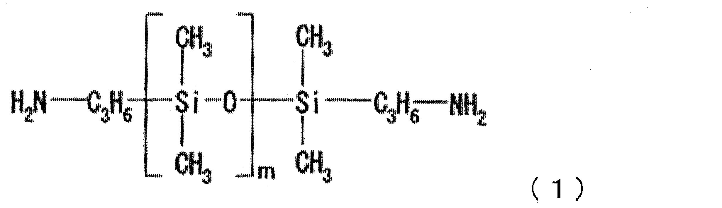
日本アエロジル株式会社製アエロジルR9200を20gとDMF80gとを混合した。得られた混合物を、回転刃式ホモジナイザー(回転刃直径は20mm)にて回転数10,000rpmで5分間攪拌を行いフュームド金属酸化物の分散液を得た。
調合例1の日本アエロジル株式会社製アエロジルR9200を日本アエロジル株式会社製アエロジルR972に変えた以外は調合例1と同様の操作を行い、フュームド金属酸化物の分散液を得た。
調合例1の日本アエロジル株式会社製アエロジルR9200を日本アエロジル株式会社製アエロジルNX130に変えた以外は調合例1と同様の操作を行い、フュームド金属酸化物の分散液を得た。
調合例1の日本アエロジル株式会社製アエロジルR9200を日本アエロジル株式会社製アエロジルVP RS920に変えた以外は調合例1と同様の操作を行い、フュームド金属酸化物の分散液を得た。
株式会社アドマテックス製アドマナノ-粒子径10nmの分散液(溶媒DMF、濃度30重量/重量%)を60gにDMF30gを混合し、分散液を得た。
株式会社アドマテックス製アドマナノ-粒子径50nmの分散液(溶媒DMF、濃度20重量/重量%)をそのまま分散液とした。
合成例1で得られたポリアミド酸溶液40gと調合例1の分散液17gとを混合し、得られた混合物に更にDMF40gおよびルチジン2gを混合し、層A分散液を得た。当該層A分散液を非熱可塑性ポリイミドフィルム(アピカルFP、厚み17ミクロン、株式会社カネカ製)の片面に最終の片面の層Aの厚みが4ミクロンとなるように塗布し、120℃×2分の条件で層A分散液の乾燥を行い、次いで残る面にも同様の手順で前記層A分散液を塗布および乾燥した。続いて、層A分散液が塗布された非熱可塑性ポリイミドフィルムを450℃で12秒間加熱して層Aのポリアミド酸をイミド化させ、層A(ポリイミド樹脂とフュームド金属酸化物とを含む)/非熱可塑性ポリイミドフィルム/層Aがこの順で積層してなる構成の樹脂フィルムを得た。尚、非熱可塑性ポリイミドフィルム(アピカルFP)は層Bに相当する。すなわち、実施例1において、層Bはポリイミド樹脂からなり、具体的に非熱可塑性ポリイミドフィルムのみから構成されている。また、当該アピカルFPの線膨張係数は12ppm/℃であった。
実施例1で用いた調合例1の分散液を調合例2の分散液に変更した以外は実施例1と同様の操作を行い、樹脂フィルム、両面銅張積層板を得、同様の評価を行った。組成および結果を表4~表7に示す。
実施例1で用いた調合例1の分散液を調合例3の分散液に変更した以外は実施例1と同様の操作を行い、樹脂フィルム、両面銅張積層板を得、同様の評価を行った。組成および結果を表4~表7に示す。
実施例1で用いた調合例1の分散液を調合例4の分散液に変更した以外は実施例1と同様の操作を行い、樹脂フィルム、両面銅張積層板を得、同様の評価を行った。組成および結果を表4~表7に示す。
合成例1で得られたポリアミド酸溶液40gとDMF40gおよびルチジン2gとを混合し、混合液を得た。実施例1で用いた層A分散液を前記混合液に変更した以外は実施例1と同様の操作を行い、樹脂フィルム、両面銅張積層板を得、同様の評価を行った。初期ピール強度は裏銅なし、裏銅ありの両者において十分な値を示さなかった。また、高温加熱処理後ピール強度は裏銅なしの場合は良好な密着性を示したが裏銅ありの場合は十分な値を示さず、裏銅の有無により密着性結果が異なった。組成および結果を表4~表7に示す。
実施例2で用いた調合例2の分散液の分量を3.4gに変更した以外は実施例2と同様の操作を行い、樹脂フィルム、両面銅張積層板を得、同様の評価を行った。組成および結果を表4~表7に示す。
実施例2で用いた調合例2の分散液の分量を6.8gに変更した以外は実施例2と同様の操作を行い、樹脂フィルム、両面銅張積層板を得、同様の評価を行った。組成および結果を表4~表7に示す。
実施例2で用いた調合例2の分散液の分量を10.2gに変更した以外は実施例2と同様の操作を行い、樹脂フィルム、両面銅張積層板を得、同様の評価を行った。組成および結果を表4~表7に示す。
実施例2で用いた調合例2の分散液の分量を34gに変更した以外は実施例2と同様の操作を行い、樹脂フィルム、両面銅張積層板を得、同様の評価を行った。組成および結果を表4~表7に示す。
実施例3で用いた調合例3の分散液の分量を3.4gに変更した以外は実施例3と同様の操作を行い、樹脂フィルム、両面銅張積層板を得、同様の評価を行った。組成および結果を表4~表7に示す。
実施例3で用いた調合例3の分散液の分量を6.8gに変更した以外は実施例3と同様の操作を行い、樹脂フィルム、両面銅張積層板を得、同様の評価を行った。組成および結果を表4~表7に示す。
実施例3で用いた調合例3の分散液の分量を10.2gに変更した以外は実施例3と同様の操作を行い、樹脂フィルム、両面銅張積層板を得、同様の評価を行った。組成および結果を表4~表7に示す。
実施例3で用いた調合例3の分散液の分量を34gに変更した以外は実施例3と同様の操作を行い、樹脂フィルム、両面銅張積層板を得、同様の評価を行った。組成および結果を表4~表7に示す。
実施例1で用いた調合例1の分散液の分量を6.8gに変更した以外は実施例1と同様の操作を行い、樹脂フィルム、両面銅張積層板を得、同様の評価を行った。組成および結果を表4~表7に示す。
実施例1で用いた調合例1の分散液の分量を10.2gに変更した以外は実施例1と同様の操作を行い、樹脂フィルム、両面銅張積層板を得、同様の評価を行った。組成および結果を表4~表7に示す。
実施例1で用いた調合例1の分散液の分量を34gに変更した以外は実施例1と同様の操作を行い、樹脂フィルム、両面銅張積層板を得、同様の評価を行った。組成および結果を表4~表7に示す。
実施例1で用いた調合例1の分散液の分量を51gに変更した以外は実施例1と同様の操作を行い、樹脂フィルム、両面銅張積層板を得、同様の評価を行った。組成および結果を表4~表7に示す。
実施例4で用いた調合例4の分散液の分量を6.8gに変更した以外は実施例4と同様の操作を行い、樹脂フィルム、両面銅張積層板を得、同様の評価を行った。組成および結果を表4~表7に示す。
実施例4で用いた調合例4の分散液の分量を10.2gに変更した以外は実施例4と同様の操作を行い、樹脂フィルム、両面銅張積層板を得、同様の評価を行った。組成および結果を表4~表7に示す。
実施例4で用いた調合例4の分散液の分量を34gに変更した以外は実施例4と同様の操作を行い、樹脂フィルム、両面銅張積層板を得、同様の評価を行った。組成および結果を表4~表7に示す。
実施例4で用いた調合例4の分散液の分量を51gに変更した以外は実施例4と同様の操作を行い、樹脂フィルム、両面銅張積層板を得、同様の評価を行った。組成および結果を表4~表7に示す。
実施例1の両面銅張積層板を作製する際の表1記載の加工条件の内、無電解銅めっき後の乾燥工程の条件を水滴拭き取りのみに変更し、また硫酸銅めっき後の乾燥工程を水滴拭き取りのみに変更した以外は実施例1と同様の操作を行い、両面銅張積層板を得、同様の評価を行った。組成および結果を表4~表7に示す。実施例21の金属化樹脂フィルム(両面銅張積層板)において、6種類のピール強度は実施例1と同様に良好な値を示した。すなわち、無電解金属めっき層形成処理後に加熱することなく、金属めっき層が樹脂フィルムに良好に密着していた。
実施例1で用いた合成例1のポリアミド酸溶液を合成例2のポリアミド酸溶液に変更した以外は実施例1と同様の操作を行い、樹脂フィルム、両面銅張積層板を得、同様の評価を行った。組成および結果を表4~表7に示す。
実施例1で用いた合成例1のポリアミド酸溶液を合成例3のポリアミド酸溶液に変更した以外は実施例1と同様の操作を行い、樹脂フィルム、両面銅張積層板を得、同様の評価を行った。組成および結果を表4~表7に示す。
実施例1で用いた合成例1のポリアミド酸溶液を合成例4のポリアミド酸溶液に変更した以外は実施例1と同様の操作を行い、樹脂フィルム、両面銅張積層板を得、同様の評価を行った。組成および結果を表4~表7に示す。
実施例1で用いた合成例1のポリアミド酸溶液を合成例5のポリアミド酸溶液に変更した以外は実施例1と同様の操作を行い、樹脂フィルム、両面銅張積層板を得、同様の評価を行った。組成および結果を表4~表7に示す。
実施例1で用いた合成例1のポリアミド酸溶液を合成例6のポリアミド酸溶液に変更した以外は実施例1と同様の操作を行い、樹脂フィルム、両面銅張積層板を得、同様の評価を行った。組成および結果を表4~表7に示す。
実施例1で用いた合成例1のポリアミド酸溶液を合成例7のポリアミド酸溶液に変更した以外は実施例1と同様の操作を行い、樹脂フィルム、両面銅張積層板を得、同様の評価を行った。組成および結果を表4~表7に示す。
実施例1で用いた合成例1のポリアミド酸溶液を合成例8のポリアミド酸溶液に変更した以外は実施例1と同様の操作を行い、樹脂フィルム、両面銅張積層板を得、同様の評価を行った。組成および結果を表4~表7に示す。
実施例1で用いた合成例1のポリアミド酸溶液を合成例9のポリアミド酸溶液に変更した以外は実施例1と同様の操作を行い、樹脂フィルム、両面銅張積層板を得、同様の評価を行った。組成および結果を表4~表7に示す。
実施例1で用いた合成例1のポリアミド酸溶液を合成例10のポリアミド酸溶液に変更した以外は実施例1と同様の操作を行い、樹脂フィルム、両面銅張積層板を得、同様の評価を行った。組成および結果を表4~表7に示す。
実施例1で用いた合成例1のポリアミド酸溶液を合成例11のポリアミド酸溶液に変更した以外は実施例1と同様の操作を行い、樹脂フィルム、両面銅張積層板を得、同様の評価を行った。吸湿半田耐熱性評価は△であった。組成および結果を表4~表7に示す。
実施例1で用いた合成例1のポリアミド酸溶液を合成例12のポリアミド酸溶液に変更した以外は実施例1と同様の操作を行い、樹脂フィルム、両面銅張積層板を得、同様の評価を行った。吸湿半田耐熱性評価は△であった。組成および結果を表4~表7に示す。
実施例1で用いた合成例1のポリアミド酸溶液を合成例13のポリアミド酸溶液に変更した以外は実施例1と同様の操作を行い、樹脂フィルム、両面銅張積層板を得、同様の評価を行った。吸湿半田耐熱性評価は×であった。組成および結果を表4~表7に示す。
実施例1で用いた合成例1のポリアミド酸溶液を合成例14のポリアミド酸溶液に変更した以外は実施例1と同様の操作を行い、樹脂フィルム、両面銅張積層板を得、同様の評価を行った。吸湿半田耐熱性評価は△であった。組成および結果を表4~表7に示す。
実施例1で用いた合成例1のポリアミド酸溶液を合成例15のポリアミド酸溶液に変更した以外は実施例1と同様の操作を行い、樹脂フィルム、両面銅張積層板を得、同様の評価を行った。吸湿半田耐熱性評価は△であった。組成および結果を表4~表7に示す。
実施例1で用いた合成例1のポリアミド酸溶液を合成例16のポリアミド酸溶液に変更した以外は実施例1と同様の操作を行い、樹脂フィルム、両面銅張積層板を得、同様の評価を行った。また、吸湿半田耐熱性評価は×であった。組成および結果を表4~表7に示す。
実施例1で用いた合成例1のポリアミド酸溶液を合成例17のポリアミド酸溶液に変更した以外は実施例1と同様の操作を行い、樹脂フィルム、両面銅張積層板を得、同様の評価を行った。層Aのポリイミド樹脂はシリコーン骨格を含んでおり、主鎖骨格中からシロキサン成分が揮発による電子機器の接点障害、工程汚染の危険性がある。また層Aは線膨張係数が大きく、吸湿半田耐熱性評価は×であった。寸法安定性に劣り、有機溶剤にも溶解性があり、プリント配線板製造工程での有機溶媒に対する耐性も劣る。組成および結果を表4~表7に示す。
合成例17のポリアミド酸溶液をフッ素系樹脂でコートしたバットにとり、真空オーブンで、200℃、120分、665Paで減圧加熱し、ポリイミド樹脂を得た。得られたポリイミド樹脂をジオキソランとトルエンの混合溶媒(混合比=50重量%/50重量%)を溶解し、17重量%のポリイミド溶液を得た。別途、日本アエロジル株式会社製アエロジルR9200を20gと前記混合溶媒80gとを混合し、得られた混合物を回転刃式ホモジナイザー(回転刃直径は20mm)にて回転数10,000rpmで5分間攪拌を行いフュームド金属酸化物の分散液を得た。前記ポリイミド溶液40gと前記フュームド金属酸化物の分散液17gを混合し、フュームド金属酸化物分散ポリイミド溶液(以下、層A溶液とも称する。)を得た。当該層A溶液を非熱可塑性ポリイミドフィルム(アピカルFP、厚み17ミクロン、株式会社カネカ製)の片面に最終の片面の層Aの厚みが4ミクロンとなるように塗布し、60℃で5分、150℃で5分の条件で層A溶液の乾燥を行い、次いで残る面にも同様の手順で前記層A溶液を塗布および乾燥した。かかる操作により、層A/非熱可塑性ポリイミドフィルム/層Aなる構成の樹脂フィルムを得た。その後は実施例1と同様の操作を行い、両面銅張積層板を得、同様の評価を行った。層Aのポリイミド樹脂はシリコーン骨格を含んでおり、主鎖骨格中からシロキサン成分が揮発による電子機器の接点障害、工程汚染の危険性がある。また、吸湿半田耐熱性評価は×であった。また層Aは線膨張係数が大きく、寸法安定性に劣り、有機溶剤にも溶解性があり、プリント配線板製造工程での有機溶媒に対する耐性も劣る。組成および結果を表4~表7に示す。


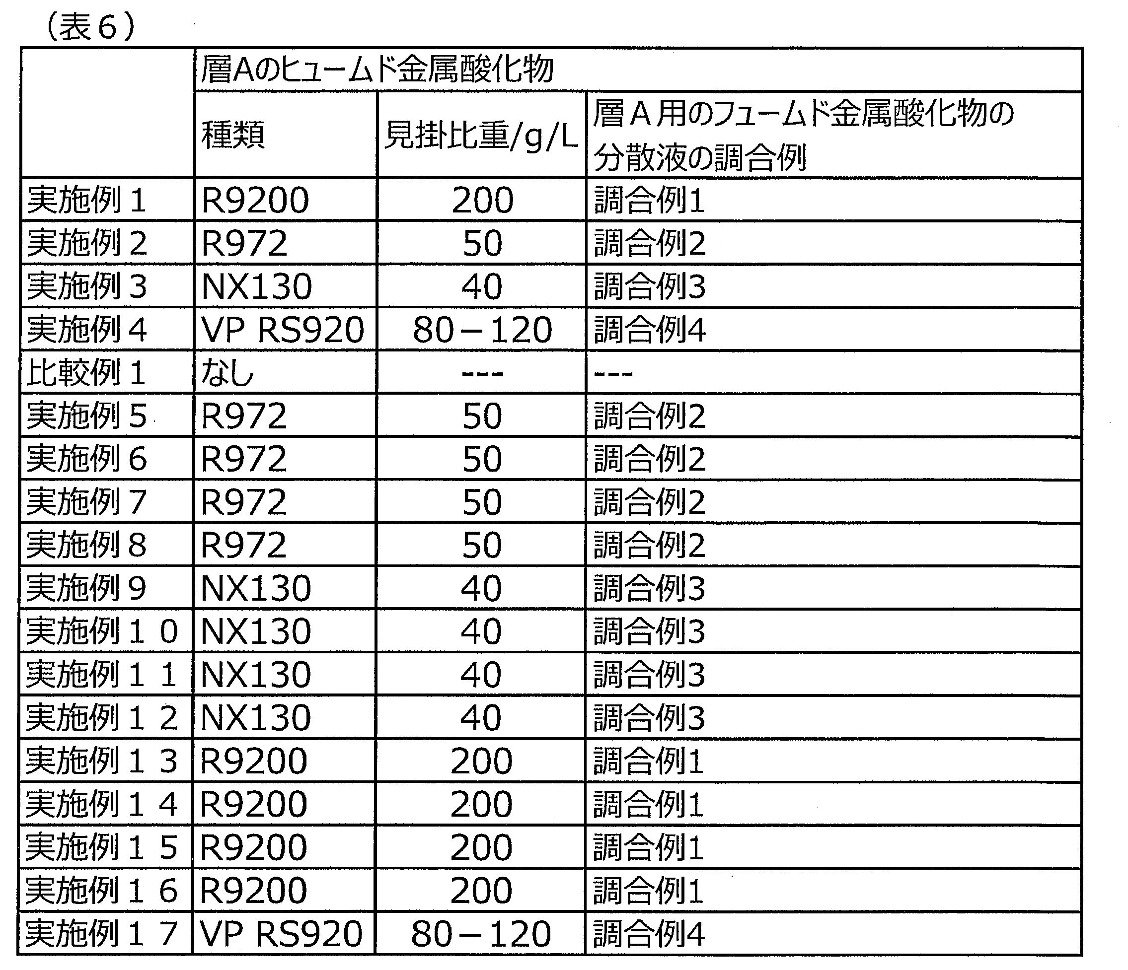


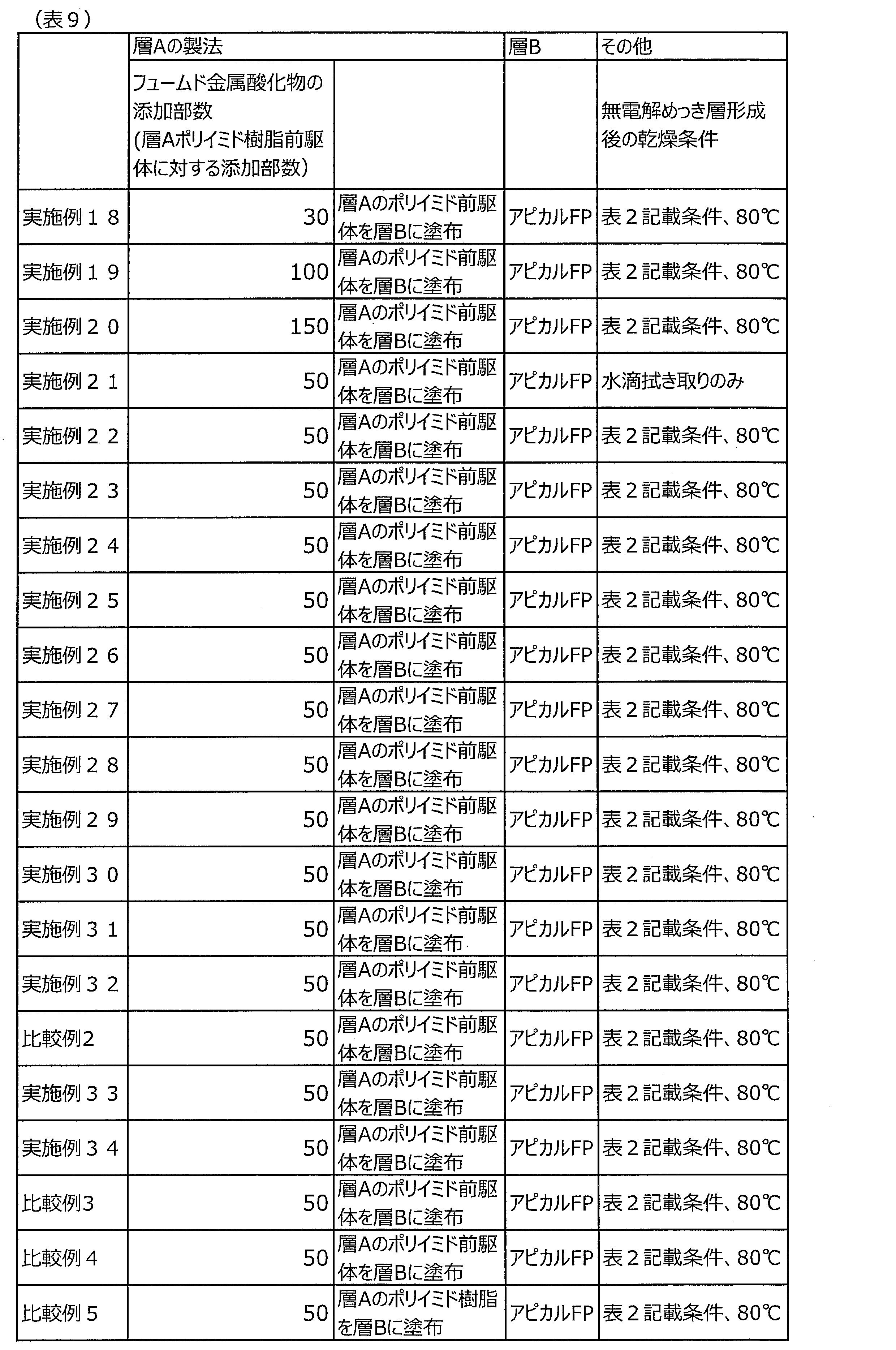
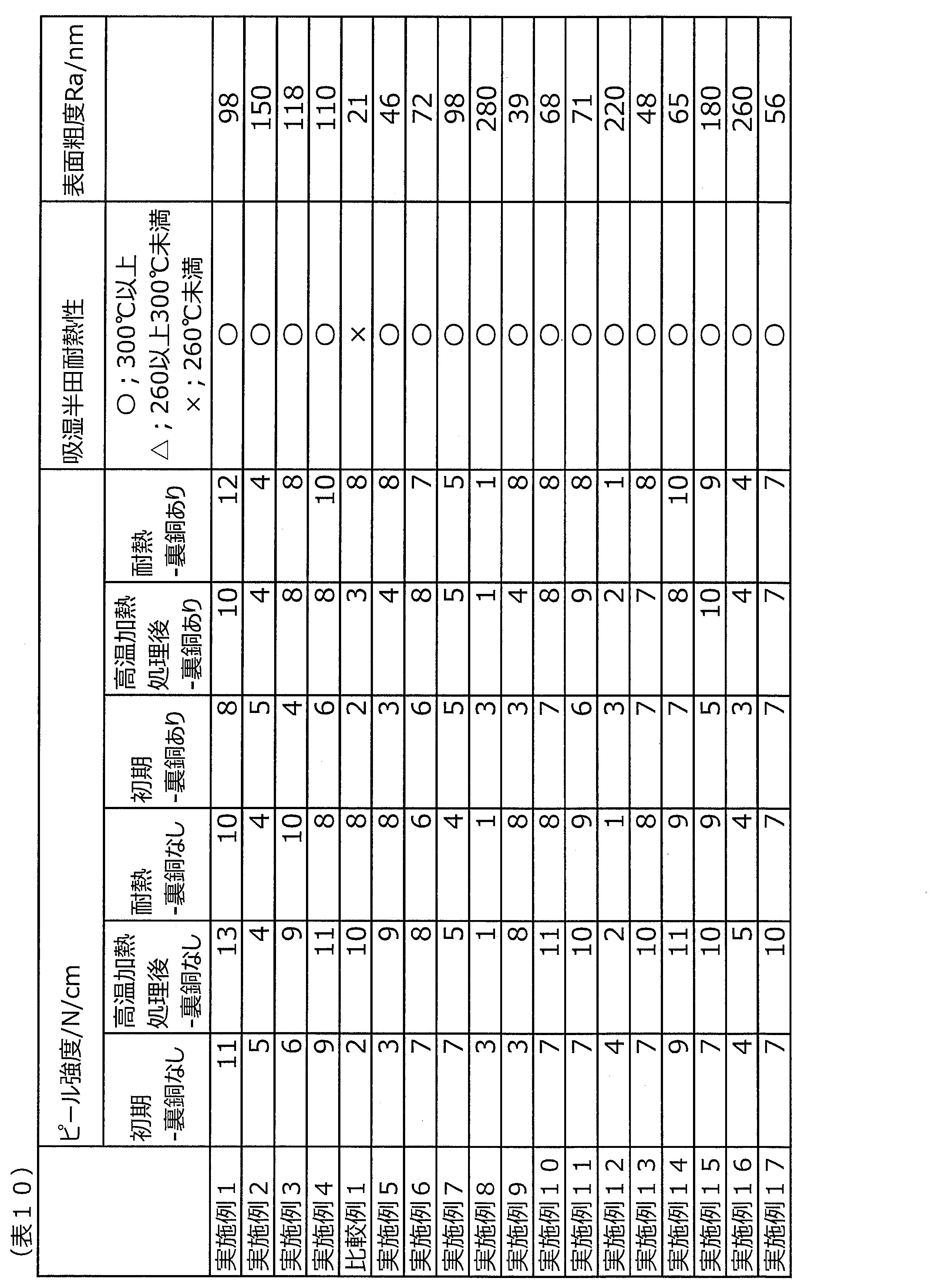

Claims (17)
- ポリイミド樹脂とフュームド金属酸化物とを含む層Aが、線膨張係数が20ppm/℃以下の耐熱性樹脂フィルムである層Bの少なくとも一方の面に形成されており、
前記ポリイミド樹脂の線膨張係数が30ppm/℃以上、100ppm/℃以下であることを特徴とする樹脂フィルム。 - 前記フュームド金属酸化物の見掛比重が20グラム/リットル以上220グラム/リットル以下であることを特徴とする請求項1に記載の樹脂フィルム。
- 前記フュームド金属酸化物の、前記ポリイミド樹脂の前駆体100重量部に対する配合部数が10重量部から130重量部であることを特徴とするであることを特徴とする請求項1に記載の樹脂フィルム。
- 前記フュームド金属酸化物がフュームドシリカであることを特徴とする請求項1に記載の樹脂フィルム。
- 前記ポリイミド樹脂と前記フュームド金属酸化物とを含む層Aが該ポリイミド樹脂の前駆体と前記フュームド金属酸化物の混合物のイミド化物であることを特徴とする請求項1に記載の樹脂フィルム。
- 前記ポリイミド樹脂の300℃における貯蔵弾性率が1×10⁸Pa以上であることを特徴とする請求項1に記載の樹脂フィルム。
- 前記ポリイミド樹脂が非溶解性ポリイミド樹脂であることを特徴とする請求項1に記載の樹脂フィルム。
- 前記層Bがポリイミド樹脂を含むことを特徴とする請求項1に記載の樹脂フィルム。
- 請求項1に記載の樹脂フィルムの、前記層Aの表面に無電解金属めっき層が形成されている金属化樹脂フィルム。
- 前記無電解金属めっきが無電解銅めっきであることを特徴とする請求項9に記載の金属化樹脂フィルム。
- 前記金属化樹脂フィルムの前記無電解金属めっき層をエッチングにより除去し、露出した前記樹脂フィルムの表面粗度Raが200ナノメートル以下であることを特徴とする請求項9に記載の金属化樹脂フィルム。
- 前記金属化樹脂フィルムにおいて、前記無電解金属めっき層を形成した後、150℃以上の加熱処理を行うことなく、5N/cm以上のピール強度を発現することを特徴とする請求項9に記載の金属化樹脂フィルム。
- 請求項1から8のいずれか1項に記載の樹脂フィルムまたは、請求項9から12のいずれか1項に記載の金属化樹脂フィルムを用いたプリント配線板。
- GHz帯の電気信号を伝送することが可能な請求項13に記載のプリント配線板。
- ポリイミド樹脂とフュームド金属酸化物とを含む層Aが、線膨張係数が20ppm/℃以下の耐熱性樹脂フィルムである層Bの少なくとも一方の面に形成されており、
前記ポリイミド樹脂の線膨張係数が30ppm/℃以上、100ppm/℃以下であり、
前記ポリイミド樹脂と前記フュームド金属酸化物とを含む前記層Aが、前記ポリイミド樹脂の前駆体のポリアミド酸溶液と前記フュームド金属酸化物とを混合し、得られたフュームド金属酸化物分散ポリアミド酸溶液をイミド化することにより得られることを特徴とする樹脂フィルムの製造方法。 - 前記フュームド金属酸化物分散ポリアミド酸溶液を前記耐熱性樹脂フィルムからなる前記層Bに塗布し、前記フュームド金属酸化物分散ポリアミド酸溶液を乾燥し、かつイミド化することを特徴とする請求項15に記載の樹脂フィルムの製造方法。
- 前記フュームド金属酸化物分散ポリアミド酸溶液を前記耐熱性樹脂フィルムからなる前記層Bの前駆体溶液と共押出し、前記フュームド金属酸化物分散ポリアミド酸溶液および前記前駆体溶液を乾燥し、かつイミド化することを特徴とする請求項15に記載の樹脂フィルムの製造方法。
Priority Applications (3)
| Application Number | Priority Date | Filing Date | Title |
|---|---|---|---|
| CN202280033445.2A CN117279782A (zh) | 2021-05-12 | 2022-04-27 | 树脂薄膜和其制造方法、以及金属化树脂薄膜、印刷电路板 |
| JP2023520971A JP7828957B2 (ja) | 2021-05-12 | 2022-04-27 | 樹脂フィルムおよびその製造方法、ならびに金属化樹脂フィルム、プリント配線板 |
| KR1020237042216A KR20240006611A (ko) | 2021-05-12 | 2022-04-27 | 수지 필름 및 그 제조 방법, 그리고 금속화 수지 필름, 프린트 배선판 |
Applications Claiming Priority (2)
| Application Number | Priority Date | Filing Date | Title |
|---|---|---|---|
| JP2021080980 | 2021-05-12 | ||
| JP2021-080980 | 2021-05-12 |
Publications (1)
| Publication Number | Publication Date |
|---|---|
| WO2022239657A1 true WO2022239657A1 (ja) | 2022-11-17 |
Family
ID=84028307
Family Applications (1)
| Application Number | Title | Priority Date | Filing Date |
|---|---|---|---|
| PCT/JP2022/019095 Ceased WO2022239657A1 (ja) | 2021-05-12 | 2022-04-27 | 樹脂フィルムおよびその製造方法、ならびに金属化樹脂フィルム、プリント配線板 |
Country Status (5)
| Country | Link |
|---|---|
| JP (1) | JP7828957B2 (ja) |
| KR (1) | KR20240006611A (ja) |
| CN (1) | CN117279782A (ja) |
| TW (1) | TW202302716A (ja) |
| WO (1) | WO2022239657A1 (ja) |
Citations (6)
| Publication number | Priority date | Publication date | Assignee | Title |
|---|---|---|---|---|
| JP5037168B2 (ja) * | 2007-02-23 | 2012-09-26 | 株式会社カネカ | 無電解めっき用材料、積層体及びプリント配線板 |
| JP2017501907A (ja) * | 2013-12-17 | 2017-01-19 | イー・アイ・デュポン・ドウ・ヌムール・アンド・カンパニーE.I.Du Pont De Nemours And Company | 多層フィルム |
| WO2017065319A1 (ja) * | 2015-10-15 | 2017-04-20 | 新日鉄住金化学株式会社 | ポリイミド積層体及びその製造方法 |
| JP2018500211A (ja) * | 2014-12-10 | 2018-01-11 | イー・アイ・デュポン・ドウ・ヌムール・アンド・カンパニーE.I.Du Pont De Nemours And Company | 多層フィルム |
| JP2019210342A (ja) * | 2018-06-01 | 2019-12-12 | 株式会社カネカ | 熱可塑性ポリイミドフィルム、多層ポリイミドフィルム、およびフレキシブル金属張積層板 |
| JP2021070727A (ja) * | 2019-10-29 | 2021-05-06 | 日鉄ケミカル&マテリアル株式会社 | 樹脂組成物、樹脂フィルム及び金属張積層板 |
Family Cites Families (6)
| Publication number | Priority date | Publication date | Assignee | Title |
|---|---|---|---|---|
| JP2006021455A (ja) * | 2004-07-09 | 2006-01-26 | Mitsui Chemicals Inc | ポリイミド金属積層体 |
| TWI296569B (en) * | 2003-08-27 | 2008-05-11 | Mitsui Chemicals Inc | Polyimide metal laminated matter |
| JP2005068347A (ja) * | 2003-08-27 | 2005-03-17 | Mitsui Chemicals Inc | ポリイミド組成物およびその製造方法と用途 |
| JP3977790B2 (ja) | 2003-09-01 | 2007-09-19 | 古河サーキットフォイル株式会社 | キャリア付き極薄銅箔の製造方法、及び該製造方法で製造された極薄銅箔、該極薄銅箔を使用したプリント配線板、多層プリント配線板、チップオンフィルム用配線基板 |
| CN105339416B (zh) * | 2013-06-28 | 2017-07-14 | 新日铁住金化学株式会社 | 聚酰亚胺、树脂膜及金属包覆层叠体 |
| JP6706013B1 (ja) | 2019-10-02 | 2020-06-03 | 住友金属鉱山株式会社 | 銅張積層板および銅張積層板の製造方法 |
-
2022
- 2022-04-27 WO PCT/JP2022/019095 patent/WO2022239657A1/ja not_active Ceased
- 2022-04-27 CN CN202280033445.2A patent/CN117279782A/zh active Pending
- 2022-04-27 JP JP2023520971A patent/JP7828957B2/ja active Active
- 2022-04-27 KR KR1020237042216A patent/KR20240006611A/ko active Pending
- 2022-05-05 TW TW111116982A patent/TW202302716A/zh unknown
Patent Citations (6)
| Publication number | Priority date | Publication date | Assignee | Title |
|---|---|---|---|---|
| JP5037168B2 (ja) * | 2007-02-23 | 2012-09-26 | 株式会社カネカ | 無電解めっき用材料、積層体及びプリント配線板 |
| JP2017501907A (ja) * | 2013-12-17 | 2017-01-19 | イー・アイ・デュポン・ドウ・ヌムール・アンド・カンパニーE.I.Du Pont De Nemours And Company | 多層フィルム |
| JP2018500211A (ja) * | 2014-12-10 | 2018-01-11 | イー・アイ・デュポン・ドウ・ヌムール・アンド・カンパニーE.I.Du Pont De Nemours And Company | 多層フィルム |
| WO2017065319A1 (ja) * | 2015-10-15 | 2017-04-20 | 新日鉄住金化学株式会社 | ポリイミド積層体及びその製造方法 |
| JP2019210342A (ja) * | 2018-06-01 | 2019-12-12 | 株式会社カネカ | 熱可塑性ポリイミドフィルム、多層ポリイミドフィルム、およびフレキシブル金属張積層板 |
| JP2021070727A (ja) * | 2019-10-29 | 2021-05-06 | 日鉄ケミカル&マテリアル株式会社 | 樹脂組成物、樹脂フィルム及び金属張積層板 |
Also Published As
| Publication number | Publication date |
|---|---|
| JPWO2022239657A1 (ja) | 2022-11-17 |
| KR20240006611A (ko) | 2024-01-15 |
| CN117279782A (zh) | 2023-12-22 |
| TW202302716A (zh) | 2023-01-16 |
| JP7828957B2 (ja) | 2026-03-12 |
Similar Documents
| Publication | Publication Date | Title |
|---|---|---|
| TWI682019B (zh) | 多層接著膜及撓性貼金屬箔積層板 | |
| KR101402635B1 (ko) | 메탈라이징용 폴리이미드 필름 및 금속적층 폴리이미드 필름 | |
| CN101960929B (zh) | 挠性基板用层叠体以及热传导性聚酰亚胺膜 | |
| JP2023115025A (ja) | 樹脂組成物 | |
| US8092900B2 (en) | Solution, component for plating, insulating sheet, laminate, and printed circuit board | |
| JP5037168B2 (ja) | 無電解めっき用材料、積層体及びプリント配線板 | |
| KR20170132680A (ko) | 수지 조성물 | |
| JP2017165909A (ja) | ポリイミド、樹脂フィルム及び金属張積層板 | |
| CN1993498B (zh) | 印刷布线板 | |
| CN116133855A (zh) | 多层聚酰亚胺薄膜 | |
| JP2000044800A (ja) | ポリイミド系複合物、ワニス、フィルム、金属張積層体および印刷配線板 | |
| US20080032103A1 (en) | Multilayer Printed Circuit Board | |
| TWI683836B (zh) | 聚醯亞胺積層膜、聚醯亞胺積層膜之製造方法、熱塑性聚醯亞胺之製造方法、及撓性貼金屬箔積層體之製造方法 | |
| JP2024066870A (ja) | ポリイミド積層体 | |
| JP4925619B2 (ja) | ポリイミド樹脂およびそれを用いた導体付きフィルム | |
| JPWO2006118230A1 (ja) | めっき用材料及びその利用 | |
| JP7828957B2 (ja) | 樹脂フィルムおよびその製造方法、ならびに金属化樹脂フィルム、プリント配線板 | |
| JP2009012366A (ja) | 積層体及びプリント配線板 | |
| JP2025049784A (ja) | 金属張積層板及びその製造方法 | |
| KR101195730B1 (ko) | 도금용 재료, 상기 도금용 재료에 사용되는 폴리아미드산 용액, 폴리이미드 수지 용액 및 이들을 사용하여 제조되는 인쇄 배선판 | |
| JP2024156378A (ja) | プリント配線板の製造方法並びに積層体 | |
| JP2006108175A (ja) | 回路基板用金属付きポリイミドフィルム及びその製造方法 | |
| TW202237765A (zh) | 電路基板 | |
| JP2024060132A (ja) | 片面銅張積層板、プリント配線板、タッチパネル用電極フィルム、および電磁波シールドフィルムの製造方法 | |
| US20250230550A1 (en) | Metallized resin film, printed wiring board, current collector film for lithium ion batteries, and method for manufacturing metallized resin film |
Legal Events
| Date | Code | Title | Description |
|---|---|---|---|
| 121 | Ep: the epo has been informed by wipo that ep was designated in this application |
Ref document number: 22807359 Country of ref document: EP Kind code of ref document: A1 |
|
| WWE | Wipo information: entry into national phase |
Ref document number: 202280033445.2 Country of ref document: CN |
|
| WWE | Wipo information: entry into national phase |
Ref document number: 2023520971 Country of ref document: JP |
|
| ENP | Entry into the national phase |
Ref document number: 20237042216 Country of ref document: KR Kind code of ref document: A |
|
| WWE | Wipo information: entry into national phase |
Ref document number: 1020237042216 Country of ref document: KR |
|
| NENP | Non-entry into the national phase |
Ref country code: DE |
|
| 122 | Ep: pct application non-entry in european phase |
Ref document number: 22807359 Country of ref document: EP Kind code of ref document: A1 |