WO2022230876A1 - レーダ装置 - Google Patents
レーダ装置 Download PDFInfo
- Publication number
- WO2022230876A1 WO2022230876A1 PCT/JP2022/018885 JP2022018885W WO2022230876A1 WO 2022230876 A1 WO2022230876 A1 WO 2022230876A1 JP 2022018885 W JP2022018885 W JP 2022018885W WO 2022230876 A1 WO2022230876 A1 WO 2022230876A1
- Authority
- WO
- WIPO (PCT)
- Prior art keywords
- radar device
- radio wave
- radome
- antenna
- waves
- Prior art date
- Legal status (The legal status is an assumption and is not a legal conclusion. Google has not performed a legal analysis and makes no representation as to the accuracy of the status listed.)
- Ceased
Links
Images


Classifications
-
- G—PHYSICS
- G01—MEASURING; TESTING
- G01S—RADIO DIRECTION-FINDING; RADIO NAVIGATION; DETERMINING DISTANCE OR VELOCITY BY USE OF RADIO WAVES; LOCATING OR PRESENCE-DETECTING BY USE OF THE REFLECTION OR RERADIATION OF RADIO WAVES; ANALOGOUS ARRANGEMENTS USING OTHER WAVES
- G01S7/00—Details of systems according to groups G01S13/00, G01S15/00, G01S17/00
- G01S7/02—Details of systems according to groups G01S13/00, G01S15/00, G01S17/00 of systems according to group G01S13/00
- G01S7/03—Details of HF subsystems specially adapted therefor, e.g. common to transmitter and receiver
-
- G—PHYSICS
- G01—MEASURING; TESTING
- G01S—RADIO DIRECTION-FINDING; RADIO NAVIGATION; DETERMINING DISTANCE OR VELOCITY BY USE OF RADIO WAVES; LOCATING OR PRESENCE-DETECTING BY USE OF THE REFLECTION OR RERADIATION OF RADIO WAVES; ANALOGOUS ARRANGEMENTS USING OTHER WAVES
- G01S13/00—Systems using the reflection or reradiation of radio waves, e.g. radar systems; Analogous systems using reflection or reradiation of waves whose nature or wavelength is irrelevant or unspecified
- G01S13/88—Radar or analogous systems specially adapted for specific applications
- G01S13/93—Radar or analogous systems specially adapted for specific applications for anti-collision purposes
- G01S13/931—Radar or analogous systems specially adapted for specific applications for anti-collision purposes of land vehicles
-
- G—PHYSICS
- G01—MEASURING; TESTING
- G01S—RADIO DIRECTION-FINDING; RADIO NAVIGATION; DETERMINING DISTANCE OR VELOCITY BY USE OF RADIO WAVES; LOCATING OR PRESENCE-DETECTING BY USE OF THE REFLECTION OR RERADIATION OF RADIO WAVES; ANALOGOUS ARRANGEMENTS USING OTHER WAVES
- G01S7/00—Details of systems according to groups G01S13/00, G01S15/00, G01S17/00
- G01S7/02—Details of systems according to groups G01S13/00, G01S15/00, G01S17/00 of systems according to group G01S13/00
- G01S7/023—Interference mitigation, e.g. reducing or avoiding non-intentional interference with other HF-transmitters, base station transmitters for mobile communication or other radar systems, e.g. using electro-magnetic interference [EMI] reduction techniques
-
- G—PHYSICS
- G01—MEASURING; TESTING
- G01S—RADIO DIRECTION-FINDING; RADIO NAVIGATION; DETERMINING DISTANCE OR VELOCITY BY USE OF RADIO WAVES; LOCATING OR PRESENCE-DETECTING BY USE OF THE REFLECTION OR RERADIATION OF RADIO WAVES; ANALOGOUS ARRANGEMENTS USING OTHER WAVES
- G01S7/00—Details of systems according to groups G01S13/00, G01S15/00, G01S17/00
- G01S7/02—Details of systems according to groups G01S13/00, G01S15/00, G01S17/00 of systems according to group G01S13/00
- G01S7/03—Details of HF subsystems specially adapted therefor, e.g. common to transmitter and receiver
- G01S7/032—Constructional details for solid-state radar subsystems
-
- G—PHYSICS
- G01—MEASURING; TESTING
- G01S—RADIO DIRECTION-FINDING; RADIO NAVIGATION; DETERMINING DISTANCE OR VELOCITY BY USE OF RADIO WAVES; LOCATING OR PRESENCE-DETECTING BY USE OF THE REFLECTION OR RERADIATION OF RADIO WAVES; ANALOGOUS ARRANGEMENTS USING OTHER WAVES
- G01S7/00—Details of systems according to groups G01S13/00, G01S15/00, G01S17/00
- G01S7/02—Details of systems according to groups G01S13/00, G01S15/00, G01S17/00 of systems according to group G01S13/00
- G01S7/03—Details of HF subsystems specially adapted therefor, e.g. common to transmitter and receiver
- G01S7/038—Feedthrough nulling circuits
-
- G—PHYSICS
- G01—MEASURING; TESTING
- G01S—RADIO DIRECTION-FINDING; RADIO NAVIGATION; DETERMINING DISTANCE OR VELOCITY BY USE OF RADIO WAVES; LOCATING OR PRESENCE-DETECTING BY USE OF THE REFLECTION OR RERADIATION OF RADIO WAVES; ANALOGOUS ARRANGEMENTS USING OTHER WAVES
- G01S7/00—Details of systems according to groups G01S13/00, G01S15/00, G01S17/00
- G01S7/02—Details of systems according to groups G01S13/00, G01S15/00, G01S17/00 of systems according to group G01S13/00
- G01S7/40—Means for monitoring or calibrating
- G01S7/4004—Means for monitoring or calibrating of parts of a radar system
-
- H—ELECTRICITY
- H01—ELECTRIC ELEMENTS
- H01Q—ANTENNAS, i.e. RADIO AERIALS
- H01Q1/00—Details of, or arrangements associated with, antennas
- H01Q1/27—Adaptation for use in or on movable bodies
- H01Q1/32—Adaptation for use in or on road or rail vehicles
- H01Q1/3208—Adaptation for use in or on road or rail vehicles characterised by the application wherein the antenna is used
- H01Q1/3233—Adaptation for use in or on road or rail vehicles characterised by the application wherein the antenna is used particular used as part of a sensor or in a security system, e.g. for automotive radar, navigation systems
-
- H—ELECTRICITY
- H01—ELECTRIC ELEMENTS
- H01Q—ANTENNAS, i.e. RADIO AERIALS
- H01Q1/00—Details of, or arrangements associated with, antennas
- H01Q1/42—Housings not intimately mechanically associated with radiating elements, e.g. radome
-
- H—ELECTRICITY
- H01—ELECTRIC ELEMENTS
- H01Q—ANTENNAS, i.e. RADIO AERIALS
- H01Q17/00—Devices for absorbing waves radiated from an antenna; Combinations of such devices with active antenna elements or systems
- H01Q17/008—Devices for absorbing waves radiated from an antenna; Combinations of such devices with active antenna elements or systems with a particular shape
-
- H—ELECTRICITY
- H01—ELECTRIC ELEMENTS
- H01Q—ANTENNAS, i.e. RADIO AERIALS
- H01Q21/00—Antenna arrays or systems
- H01Q21/06—Arrays of individually energised antenna units similarly polarised and spaced apart
- H01Q21/061—Two dimensional planar arrays
- H01Q21/065—Patch antenna array
-
- G—PHYSICS
- G01—MEASURING; TESTING
- G01S—RADIO DIRECTION-FINDING; RADIO NAVIGATION; DETERMINING DISTANCE OR VELOCITY BY USE OF RADIO WAVES; LOCATING OR PRESENCE-DETECTING BY USE OF THE REFLECTION OR RERADIATION OF RADIO WAVES; ANALOGOUS ARRANGEMENTS USING OTHER WAVES
- G01S13/00—Systems using the reflection or reradiation of radio waves, e.g. radar systems; Analogous systems using reflection or reradiation of waves whose nature or wavelength is irrelevant or unspecified
- G01S13/88—Radar or analogous systems specially adapted for specific applications
- G01S13/93—Radar or analogous systems specially adapted for specific applications for anti-collision purposes
- G01S13/931—Radar or analogous systems specially adapted for specific applications for anti-collision purposes of land vehicles
- G01S2013/9327—Sensor installation details
- G01S2013/93275—Sensor installation details in the bumper area
Definitions
- the present disclosure relates to radar equipment.
- Millimeter-wave radars are known, which are used for purposes such as automatic driving of vehicles and collision prevention.
- a millimeter-wave radar is a radar for detecting the existence of an object within a predetermined detection area and the distance to the object by radiating radio waves and detecting reflected waves of the radiated radio waves reflected by an object.
- Performance degradation occurs when unwanted waves, which are radio waves that stray from the detection area or wrap around unintended areas, become interference waves, disturbing the phase of radar waves and causing errors in object orientation detection.
- a known main unwanted wave is, for example, a reflected wave from a bumper.
- Patent Document 1 discloses a technique for suppressing the influence of unwanted waves by providing an absorbing element made of a material that absorbs electromagnetic waves in a radar device.
- One aspect of the present disclosure provides a technology that solves problems that may occur when installing an absorbing element and reduces azimuth detection errors by a radar device.
- the antenna section includes an antenna surface on which one or more antennas that emit radio waves are installed, and is configured to emit target radio waves in a predetermined frequency band.
- the cover part is configured to be provided at a position through which the target radio wave is transmitted.
- the radio wave suppression part is integrated with the cover part in a detection range outside the range of the detection angle of the antenna part on the outer surface of the cover part, and comprises a conductive part having conductivity and a non-conductive part having no conductivity. and a conductive portion.
- the radio wave suppression unit suppresses unwanted waves traveling outside the radar device and unwanted waves traveling inside the radar device, so that these unwanted waves do not interfere with the direct waves radiated within the detection area. It is possible to suppress the occurrence of an error in azimuth detection due to Moreover, since there is no need to newly install an absorbing element, it is possible to reduce manufacturing costs and azimuth detection errors that may occur due to variations in installation accuracy when installing the absorbing elements. In other words, it is possible to solve the problem that may occur when installing the absorbing element, and to reduce the azimuth detection error by the radar device.
- FIG. 2 is a cross-sectional view taken along line II-II in FIG. 1;
- FIG. 2 is a cross-sectional view taken along line III-III in FIG. 1;
- FIG. 4 is an explanatory diagram in which the configuration of the antenna section 341 is projected onto the cross-sectional view taken along line IV-IV in FIG. 3;
- It is an explanatory view explaining an out-of-detection range field.
- It is an explanatory view explaining the electric wave suppression part of the embodiment.
- It is an explanatory view explaining the electric wave suppression part of the embodiment.
- It is an explanatory view explaining an unnecessary wave.
- It is explanatory drawing explaining the effect
- FIG. 1 is a cross-sectional view taken along line II-II in FIG. 1
- FIG. 2 is a cross-sectional view taken along line III-III in FIG. 1
- FIG. 4 is an explanatory diagram in which the configuration of the antenna section 341 is projected
- 11 is an explanatory diagram for explaining a radio wave suppression unit of Modification 1; It is an explanatory view explaining the object of simulation. It is a graph which shows the improvement effect of S11 by simulation. It is a graph which shows the improvement effect of S21 by simulation. It is explanatory drawing explaining the example which equips a radome non-facing surface with the radio wave suppression part in other embodiment. It is explanatory drawing explaining the example which equips a bumper opposing surface with the radio wave suppression part in other embodiment. It is explanatory drawing explaining the example which equips the bumper opposing surface with the electromagnetic wave suppression part of the modification 1 in other embodiment.
- perpendicular referred to below is not limited to being perpendicular in a strict sense, and may not be strictly perpendicular as long as the same effect is achieved. The same applies to “odd multiple” and “equal to”.
- the radar device 1 of the present embodiment shown in FIG. 1 is a device for measuring at least the distance to an object existing within a predetermined detection range by being mounted on a vehicle and transmitting/receiving target radio waves.
- the target radio wave is a radio wave in a predetermined frequency band, and for example, a millimeter wave is used. In this embodiment, millimeter waves with a frequency of 77 GHz band are used, but the frequencies used are not limited to this.
- the radar device 1 is fixed, for example, to a metal plate surface that is part of the body 9 of the vehicle, located inside the bumper 8 of the vehicle.
- the radar device 1 includes a lower case 31, a radome 32, a connector 33, a circuit board 34, and a radio wave suppressor .
- the lower case 31 is a box-shaped member made of a radio-impermeable material.
- the lower case 31 has a rectangular parallelepiped outer shape, and one surface is open.
- the radome 32 is a plate-shaped member made of a resin material that transmits radio waves.
- the radome 32 is provided at a position through which the target radio wave is transmitted. Radome 32 is attached to lower case 31 so as to close the opening of lower case 31 .
- the lower case 31 and the radome 32 form a space for housing the circuit board 34.
- the lower case 31 and the radome 32 are collectively called a housing.
- a connector 33 is provided on the side wall of the lower case 31 .
- the connector 33 is used to electrically connect an electronic circuit on the circuit board 34 (that is, a transmission/reception circuit section 342 to be described later) and a vehicle on which the radar device 1 is mounted.
- the circuit board 34 includes an antenna section 341 and a transmission/reception circuit section 342 .
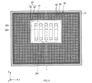
- the antenna unit 341 is configured, for example, by arranging a plurality of patch antennas 343 in a two-dimensional array, and transmits and receives target radio waves.
- a surface on which the antenna portion 341 is formed is called an antenna surface 35 .
- the long side direction of the circuit board 34 is the x-axis direction
- the short side direction is the y-axis direction
- the axial direction perpendicular to the antenna surface 35 is the z-axis direction.
- the xyz three-dimensional coordinate axes are used as appropriate.
- the side on which the radiation wave is radiated with the antenna surface 35 as a boundary is the plus side of the z-axis
- the opposite side is the minus side of the z-axis.
- Arranging a plurality of patch antennas 343 in a two-dimensional array means that a plurality of patch antennas 343 are arranged two-dimensionally along the x-axis direction and the y-axis direction.
- a plurality of (for example, seven) patch antennas 343 arranged in a row along the y-axis direction are each formed into one array antenna (hereinafter referred to as a unit antenna 344 ). That is, as shown in FIGS. 3 and 4, the antenna section 341 has a structure in which a plurality of (eg, five) unit antennas 344 are arranged along the x-axis direction.
- the number of patch antennas 343 included in the unit antenna 344 and the number of unit antennas 344 included in the antenna section 341 are not limited to this.
- any one of the plurality of unit antennas 344 can be used as a transmitting antenna, and the others can be used as receiving antennas. That is, in the radar device 1, the direction of direction detection is the x-axis direction in which the unit antennas 344 are arranged.
- the aspect of the transmitting antenna and the receiving antenna is not limited to this, and the number and arrangement of the unit antennas 344 used as transmitting antennas and the unit antennas 344 used as receiving antennas can be set arbitrarily. . Also, all the unit antennas 344 may be used as transmitting antennas, or all the unit antennas 344 may be used as receiving antennas.
- the transmission/reception circuit section 342 includes a circuit that generates transmission signals to be supplied to the antenna section 341 according to commands input through the connector 33 .
- the transmitting/receiving circuit section 342 includes a circuit or the like that performs signal processing such as down-conversion on the received signal supplied from the antenna section 341 and outputs the processed signal through the connector 33 .
- the xyz-axis directions of the circuit board 34 are also applied to the radar device 1 in which the circuit board 34 is attached to the lower case 31 .
- the radar device 1 is fixed to the vehicle so that the y-axis direction coincides with the vehicle height direction, the x-axis direction coincides with the horizontal direction, and the z-axis direction coincides with the center direction of the detection area.
- the detection area is a predetermined angular range (hereinafter referred to as a predetermined (also called angular range ⁇ x).
- the predetermined angular range ⁇ x is set to -60° to +60°, for example.
- the predetermined angle range ⁇ x is not limited to ⁇ 60° to +60°, and may be set to a narrower angle than this, or may be set to a wider angle than this.
- the detection area is a predetermined angular range (hereinafter referred to as , a predetermined angular range ⁇ y).
- the predetermined angle range ⁇ y is set to be narrower than the predetermined angle range ⁇ x.
- the radome 32 has a radio wave suppressor 36 on the radome facing surface 321 as shown in FIGS.
- the radome facing surface 321 is a surface of the outer surface of the radome 32 that faces (that is, faces) the antenna surface 35 .
- the outer surface refers to the exposed surface.
- the outer surface that does not face the antenna surface 35 is called a radome non-facing surface 322 .
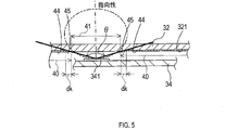
- the radio wave suppression unit 36 is provided within the detection outside area 40 on the radome facing surface 321 .
- the out-of-detection range area 40 is, as shown in FIG. 5, an area outside the range of the detection angle ⁇ of the antenna section 341 (that is, the detection area of the antenna section 341).
- ⁇ may be the above-described ⁇ x or ⁇ y.
- projection region 41 a region obtained by projecting the range of the detection angle ⁇ of the antenna unit 341 onto the radome-facing surface 321 (hereinafter, projection region 41) is within the range of the detection angle ⁇ of the antenna unit 341 on the radome-facing surface 321 (that is, the detection area). corresponds to the area of
- the out-of-detection-range area 40 refers to an area outside the projection area 41 on the radome-facing surface 321 .
- the radio wave suppressor 36 is provided in substantially the entire detection range area 40 on the radome facing surface 321 .
- the radio wave suppression unit 36 controls the remaining area (hereinafter also referred to as the formation area 44) of the detection range area 40 except for the preliminary area 45 which is a predetermined distance dk away from the projection area 41. ).
- the forming region 44 is a region in which the radio wave suppressor 36 is provided (that is, formed) in the detection range outside region 40 .
- the predetermined length dk can be appropriately set to a length such that the radio wave suppressing section 36 does not affect the directivity of the antenna section 341 .
- the radio wave suppressing section 36 includes a conducting section 50 having conductivity and a non-conducting section 60 having no conductivity. Having conductivity here means that the conductivity is 1 S/m or more.
- the conductive portion 50 is a portion of the radome-facing surface 321 where the material of the radome 32 is changed.
- the conductive portion 50 has conductivity by changing the material of the radome 32 and is integrated with the radome 32 .
- a portion other than the conductive portion 50 in the radio wave suppression portion 36 is referred to as a non-conductive portion 60 .
- the part where the material of the radome 32 is changed is the part where the resin, which is the material of the radome 32, is carbonized.
- Resin can be changed in material so as to have conductivity by being carbonized by the application of heat.
- the electrical conductivity obtained by carbonizing the resin is about 10-100 S/m.
- Aromatic resin can be used as the resin as the material of the radome 32 .
- Examples include PBT (ie, polybutylene terephthalate), PPS (ie, polyphenylene sulfide), PI (ie, polyimide), phenol, and the like.
- the conductive portion 50 is a portion of the radome-facing surface 321 that has conductivity due to the carbonization of the resin that is the material of the radome 32.
- the resin is removed by irradiating the resin with a laser beam. Carbonize.
- the conductive portion 50 is formed by appropriately irradiating a laser beam onto a portion of the radome-facing surface 321 where unwanted waves, which will be described later, are desired to be suppressed (that is, here, substantially the entire area outside the detection range 40 of the radome-facing surface 321). be done.
- the radio wave suppressor 36 is integrated with the radome 32 .
- integrated refers to being formed as a part of the radome 32 (that is, integrally formed) without adding new parts to the radome 32 .
- the radio wave suppressor 36 includes a plurality of projections 70 having a shape projecting from the radome facing surface 321. As shown in FIG. The projecting portion 70 is made of the same material as the radome 32 . A remaining portion of the radio wave suppressing portion 36 excluding the protrusion 70 , that is, a remaining portion excluding the protrusion 70 from within the formation region 44 of the radome-facing surface 321 is referred to as a non-protruding portion 71 .
- Each protruding portion 70 has a substantially cubic shape, and the plurality of protruding portions 70 are arranged at a pitch interval P, which is a predetermined interval, along the x direction and the y direction. That is, the top surface 324, which is the surface of the protrusion 70 and faces in the direction of protrusion (that is, the -z direction), has a substantially square shape. Here, the length of one side of the top surface 324 (that is, the width D of the projecting portion 70) and the projecting height H of the projecting portion 70 from the radome-facing surface 321 are equal. Then, of the radio wave suppressing portion 36, the conductive portion 50 is formed on both the top surface 324 in the projecting direction (that is, the -z direction) and the non-projecting portion 71 on the surface of the projecting portion 70. .
- the conductive portion 50 has a substantially square shape, which is a predetermined shape, and has specific directions of x and y. can be said to be arranged at a pitch interval P, which is a predetermined interval.
- the specific direction is the direction in which the conductive portions 50 are arranged.
- the conductive portion 50 of the protruding portion 70 is formed by irradiating a substantially square laser beam in order at pitch intervals P along the x-direction or along the y-direction.
- the conductive portion 50 has a linear shape that is a predetermined shape, and along the specific directions of the x direction and the y direction, It can be said that they are arranged at predetermined intervals (that is, the width D of the projecting portion 70).
- the straight line referred to here means a straight line having a line width equal to the pitch interval P.
- the conductive portion 50 of the protruding portion 70 is formed by irradiating a linear laser beam having a line width of the pitch interval P in order for each width D of the protruding portion 70 along the x direction or along the y direction. It is formed. In other words, focusing on the non-protruding portion 71, the conductive portion 50 is formed in a grid pattern.
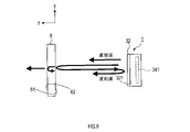
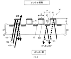
- radiation waves (hereinafter also referred to as direct waves) directly radiated from the radar device 1 (that is, the antenna section 341) are radiated to the outside of the radar device 1 via the radome 32.
- a portion of the direct wave can be reflected once by the bumper 8 or multiple-reflected between the bumper 8 and the radome 32 to become a reflected wave toward the radar device 1 or toward the bumper 8 .
- it is a part of the direct wave and is a reflected wave toward the radar device 1 due to reflection between the bumper 8 and the radome 32 (that is, a reflected wave toward the inside of the housing of the radar device 1) or a reflected wave toward the bumper 8.
- a wave is called an unwanted wave.
- Such unwanted waves may cause an error in direction detection by interfering with direct waves (that is, radar waves) radiated into the detection area outside and inside the radar device 1 .
- the projection height H of the projecting portion 70 in the radio wave suppressing portion 36 is set to ⁇ /4. Therefore, the reflected wave 101 from the conductive portion 50 of the projecting portion 70 and the reflected wave 102 from the conductive portion 50 of the non-projecting portion 71 are out of phase by nearly 180° and cancel each other. That is, the reflection characteristic of the target radio wave in the radome 32 (that is, the so-called S11 characteristic) has a relatively small value at the frequency of the target radio wave.
- the radio wave suppression unit 36 suppresses unnecessary waves traveling outside the radar device 1 (that is, traveling toward the bumper 8). This prevents the unnecessary waves from interfering with the direct waves radiated into the detection area due to multiple reflections with the bumper 8 and causing errors in the azimuth detection (that is, becoming interference waves). be done.
- both the top surface 324 of the protruding portion 70 and the non-protruding portion 71 have the conductive portion 50, so that reflected waves from the bumper 8 toward the radome 32 enter the housing. Hard to penetrate. This is because reflected waves from the bumper 8 toward the radome 32 can only pass through the side surfaces of the projecting portion 70 excluding the top surface 324 into the housing. For example, among the reflected waves 103 to 105 shown in FIG. 9, the reflected wave 105 is transmitted into the housing, but the reflected waves 103 to 104 are reflected by the conductive portion 50 and cannot be transmitted into the housing.
- waves other than reflected waves eg, reflected waves 105 directed from the bumper 8 toward the radome 32 at a certain angle cannot be transmitted into the housing.
- the transmission characteristic of the target radio wave in the radome 32 (that is, the so-called S21 characteristic) has a relatively small value.
- the radio wave suppression unit 36 suppresses unnecessary waves traveling toward the inside of the radar device 1 (that is, from the bumper 8).
- the unwanted wave interferes with the direct wave radiated within the detection area due to multiple reflection or the like in the radar device 1, causing an error in azimuth detection (that is, becoming an interference wave). is suppressed.
- the radio wave suppression unit 36 is integrated with the radome 32, and as a result, acts to suppress the influence of unwanted waves on the azimuth detection error of an object, like a so-called absorption element that absorbs electromagnetic waves.
- the radio wave suppressor 36 is integrated with the radome 32 in the detection range outside region 40 of the radome facing surface 321 of the radome 32, and the conductive portion 50 and the non-conductive portion 60.
- the radio wave suppression unit 36 suppresses unnecessary waves directed to the outside of the radar device 1 and unwanted waves directed to the inside of the radar device 1, these unnecessary waves interfere with the direct waves radiated within the detection area, resulting in an error in direction detection. can be suppressed. Moreover, since there is no need to newly install an absorbing element, it is possible to reduce manufacturing costs and azimuth detection errors that may occur due to variations in installation accuracy when installing the absorbing elements.
- the radar device 1 can solve the problems that may occur when installing the absorbing element, and reduce the azimuth detection error by the radar device 1 .
- the weight of the radar device 1 can be reduced, and the thickness of the radar device 1 can be reduced (that is, z direction) can be achieved. In this way, the radar device 1 can solve the problem that may occur when installing the absorbing element, and reduce the azimuth detection error by the radar device 1 .
- the conductive portion 50 is a portion where the material of the radome 32 is changed.
- the portion where the material has changed specifically means a portion where the material is carbonized.
- part of the radome 32 is used as the conductive portion 50 (that is, the radio wave suppression portion 36), so that manufacturing costs can be further reduced.
- the radar device 1 can be made lighter and thinner.
- the radio wave suppressor 36 has the conductive portions 50 having a predetermined shape and arranged at predetermined intervals along a predetermined specific direction. . That is, the conductive portions 50 are arranged with periodicity in a specific direction. Accordingly, by appropriately setting the shape, spacing, etc. of the conductive portions 50, the unwanted waves can be in opposite phases and can be canceled and attenuated more than when the conductive portions 50 are arranged without periodicity. can enhance sexuality. As a result, the direction detection error by the radar device 1 can be suppressed. In addition, since the conductive portions 50 are arranged with periodicity, the work efficiency in carbonizing by irradiating the laser light can be improved as compared with the case where the conductive portions 50 are arranged without periodicity.
- the radio wave suppressor 36 includes the projecting portion 70 and the non-projecting portion 71, and the projecting portions 70 are arranged at predetermined intervals along the specific direction, and project At least one of the surface of the portion 70 and the non-projecting portion 71 is provided with the conductive portion 50 . Accordingly, by appropriately setting the projection height H of the projecting portion 70, it is possible to increase the possibility that the unwanted waves will have opposite phases and cancel each other out and be attenuated. Further, since the radio wave suppressing portion 36 includes the conductive portion 50 on at least one of the surface of the protruding portion 70 and the non-protruding portion 71, unwanted waves can be attenuated. As a result, the azimuth detection error of the radar device 1 can be suppressed.
- the radio wave suppressor 36 includes the conductive portion 50 on both the surface of the non-protruding portion 71 and the protruding portion 70 .
- the radio wave suppressing portion 36 includes more conductive portions 50 than when one of the protruding portion 70 and the non-protruding portion 71 is provided with the conductive portion 50, so that unnecessary waves can be more attenuated.
- the azimuth detection error of the radar device 1 can be further suppressed.
- the protrusion height H of the protrusion 70 is an odd multiple of ⁇ /4.
- the protrusion height H of the protrusion 70 is not an odd multiple of ⁇ /4, it is possible to further increase the possibility that the unwanted waves will have opposite phases and cancel each other out and be attenuated.
- the azimuth detection error of the radar device 1 can be further suppressed.
- the interval between the adjacent protrusions 70 (that is, the pitch width P) is an odd multiple of ⁇ /4 in a specific direction. This makes it possible to increase the possibility that unwanted waves (e.g., unwanted waves that propagate particularly in a specific direction) will have opposite phases, cancel each other out, and be attenuated. As a result, the azimuth detection error of the radar device 1 can be further suppressed.
- the specific direction in which the conductive portions 50 are arranged with regularity includes the x-direction and the y-direction perpendicular to the x-direction.
- the conductive portions 50 are arranged perpendicular to each other in a grid pattern. are arranged in As a result, the conductive portions 50 are perpendicular to each other, so that it is possible to further improve the work efficiency when irradiating and carbonizing the laser beam.
- the radome 32 corresponds to the cover portion
- the unit antenna 344 corresponds to the antenna
- the radome facing surface 321 corresponds to the outer surface of the cover portion.
- a substantially square having a side length of D corresponds to a predetermined shape
- the x direction and the y direction correspond to specific directions
- the pitch interval P corresponds to a predetermined interval.
- a straight line having a line width equal to the pitch interval P corresponds to a predetermined shape
- the x direction and the y direction correspond to specific directions
- the width D corresponds to a predetermined interval.
- the x direction corresponds to the first direction
- the y direction corresponds to the second direction.
- Modification 1 Since Modification 1 has the same basic configuration as the above-described embodiment, differences will be described below. The same reference numerals as in the above-described embodiment indicate the same configuration, and the preceding description is referred to.
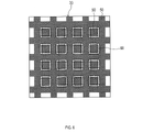
- the radome 32 is provided with a radio wave suppressor 36a. As shown in FIG. 10 , the radio wave suppressor 36 a does not have the projecting portion 70 .
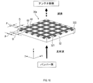
- the radio wave suppressing portion 36a is provided on the radome-facing surface 321 of the radome 32 with a conductive portion 50 having a linear shape with a line width equal to the pitch interval P described above and having a width D described above along the x and y directions. Arranged by intervals. That is, in the radio wave suppressing portion 36a, the conductive portions 50 are arranged perpendicular to each other in a grid pattern. This makes it possible to obtain the same effects as (1a)-(1c) and (1h) described above.
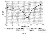
- FIG. 12 shows the result of calculating S11 in the range of 60 GHz to 90 GHz based on the signal acquired by the antenna section 341 by simulation.
- a thick solid line is the embodiment of the present disclosure, a thin solid line is Modification 1, a short dashed line is Comparative Example 1 described later, and a long dashed line is Comparative Example 2 described later.
- a radio wave absorber 201 that is, an absorption element .
- PBT mixed with carbon fiber as a filler was used.
- the radio wave suppressing portion 36a is formed by two-color molding so that the same area as the formation area 44 of the radome 32 is made of PBT mixed with carbon fiber as a filler, and the remaining portion is made of carbon fiber as a filler. It was formed by unmixed PBT as
- the radome 32 was formed using PBT.
- the projecting portion 70 and the non-projecting portion 71 similar to the radio wave suppressing portion 36 of the embodiment of the present disclosure are formed in the radome 32, and both the projecting portion 70 and the non-projecting portion 71 form the conductive portion 50.
- the configuration is not prepared.
- Modification 1 is, as described above, a conductive portion 50 having a linear shape with a line width equal to the pitch interval P in the radome 32 formed of PBT in a plate shape without forming the projecting portion 70 , and extending in the x direction. and arranged at intervals of width D along the y direction.
- S11 is smaller than Comparative Examples 1 and 2 (that is, the reflected wave is greatly suppressed), especially near the frequency of the target radio wave (that is, 77 GHz). .
- the above-described unnecessary waves which may be reflected by the radome 32 and directed toward the bumper 8, are greatly suppressed.
- FIG. 13 shows the result of calculating S21 in the range of 60 GHz-90 GHz based on the signal acquired by the antenna section 341 through simulation.
- S21 is about the same as or smaller than Comparative Example 1 (that is, the transmitted wave is greatly suppressed) in almost the entire range of 60 GHz-90 GHz.
- unnecessary waves which may cause reflection waves from the bumper 8 to pass through the radome 32 and be multiple-reflected inside the housing, are suppressed to the same extent as in the first comparative example or more.
- S21 is approximately the same as in Comparative Example 1.
- unnecessary waves which may cause reflected waves from the bumper 8 to pass through the radome 32 and be reflected within the housing, are suppressed to the same extent as in the first comparative example.
- the radio wave suppressing portion 36 of the present disclosure and the radio wave suppressing portion 36a of Modification 1 are parts integrated with the radome 32, and are equivalent to or more than Comparative Example 1 (that is, the absorbing element) ( In other words, it can be seen that this is a portion that can largely suppress unnecessary waves.
- the radio wave suppressing unit 36 of the present disclosure and the radio wave suppressing unit 36a of Modification 1 have the effect of suppressing direction detection errors.
- the radio wave suppression unit 36 of the embodiment of the present disclosure has a greater effect of suppressing the azimuth detection error than the first modification.
- the radio wave suppressing portions 36 and 36a are insulated by covering at least the conductive portion 50 with a film or coating, an adhesive, or an adhesive sheet. It may be configured as As a result, the conductive portion 50 is insulated, and peeling of the carbonized resin from the conductive portion 50 can be suppressed.
- the film is desirably the same material as the material of the radome 32, for example, from the viewpoint of suppressing peeling due to the difference in linear expansion and from the viewpoint of cost reduction due to process integration. However, it is not necessarily the same material as the material of the radome 32, and acrylic, PET (that is, polyethylene terephthalate), PC (that is, polycarbonate), etc. can be used.
- the conductive portions 50 having a linear shape with a line width of the pitch interval P are spaced apart by a width D along the x direction and the y direction. , but the line width may not be constant. Also, the intervals may not be constant.
- the conductive portion 50 has a predetermined shape and extends along at least one predetermined specific direction. Multiple arrays are arranged at intervals.
- the predetermined shape can be linear, circular, polygonal, elliptical, and various other shapes.
- the specific direction may be a direction in which the direction can be detected by the antenna unit 341 or any other direction.
- the specific direction may be one direction or multiple directions. Moreover, when there are a plurality of specific directions, these directions may or may not be orthogonal to each other.
- the intervals at which they are arranged may be predetermined constant intervals, or may not be predetermined constant intervals.
- the projection heights H of all the projections 70 in the radio wave suppression units 36 and 36a may not be uniform.
- the intervals between all the protruding portions 70 may not be uniform.
- the projection height H or the pitch interval P of the projections 70 may be different depending on the position of the projections 70 depending on the frequency of unwanted waves to be suppressed.
- the shape of the projecting portion 70 is not limited to a cube, and may be any shape such as a column, a polygonal column, or the like.
- the conductive portion 50 can be formed only in the protruding portion 70 of the protruding portion 70 and the non-protruding portion 71 in the radio wave suppression portion 36 .
- the conductive portion 50 may be formed only on the non-protruding portion 71 .
- the conductive section 50 may be formed on the side surface of the protruding section 70 in addition to the top surface 324 .
- the radio wave suppressing portion 36 has a stepped portion that is similar to the projecting portion 70 and arranged in a plurality of steps along the z-axis direction, such as two steps, three steps, and so on. can have the shape Then, the conductive portion 50 can be formed on the top surfaces of the first stage, second stage, third stage, and so on (that is, the surface in the -z direction, which is the projecting direction).
- the thickness of the conductive portion 50 may not be uniform in the radio wave suppression portions 36 and 36a.
- the greater the thickness of the carbonized portion the greater the electrical conductivity.
- the thickness of the conductive portion 50 may be made larger than the thickness of the conductive portion 50 provided in other portions.
- the radio wave suppression units 36 and 36a may be provided over the entire detection range area 40 of the radome facing surface 321 .
- the radio wave suppression units 36 and 36a may be provided in predetermined arbitrary regions of the detection range outside region 40 of the radome facing surface 321 .
- the radio wave suppression units 36 and 36a may be provided at one location or at a plurality of locations in the out-of-detection-range region 40 of the radome-facing surface 321 .
- the size of the region in which the radio wave suppressors 36 and 36a are provided may be any predetermined size.
- the radio wave suppression units 36 and 36a may be provided on the radome non-facing surface 322 as shown in FIG.
- FIG. 14 shows the forming region 44 on the radome non-facing surface 322 .
- the formation region 44 may be provided with either the radio wave suppressor 36 or 36a.
- the radome 32 corresponds to the cover portion
- the radome non-facing surface 322 corresponds to the outer surface of the cover portion.
- At least one of the radome 32, the bumper 8, and the emblem may be provided with the radio wave suppression units 36 and 36a.
- the radio wave suppressing portions 36, 36a are, as shown in FIGS. 15 and 16, the surfaces of the outer surface of the bumper 8a facing the antenna surface 35 (that is, the surfaces facing the radar device 1). It may be provided on the bumper facing surface 81 .
- the bumper 8a corresponds to the cover portion
- the bumper facing surface 81 corresponds to the outer surface of the cover portion.
- the radio wave suppression units 36 and 36a are the surfaces of the bumper 8a shown in FIGS. It may be provided on face 82 .
- the bumper 8a corresponds to the cover portion
- the non-bumper facing surface 82 corresponds to the outer surface of the cover portion.
- the bumper 8a in FIGS. 15 and 16 may be replaced with the emblem of the vehicle.
- the radio wave suppressor 36, 36a may be provided on the outer surface of the emblem facing the antenna surface 35 (that is, the radar device 1).
- the emblem corresponds to the cover portion
- the surface of the emblem facing the antenna surface 35 corresponds to the outer surface of the cover portion.
- the radio wave suppressor 36 may be provided on a surface of the emblem attached to the vehicle that does not face the antenna surface 35 (that is, the radar device 1).
- the emblem corresponds to the cover portion
- the surface of the emblem that does not face the antenna surface 35 corresponds to the outer surface of the cover portion.
- the conductive unit 50 is integrated with the radome 32 by vapor-depositing metal (for example, aluminum) on the radome 32 so as to have conductivity. may be formed in Alternatively, the conductive portion 50 may be integrated with the radome 32 by adhering a metal thin film to the radome 32 with an adhesive or the like so as to be conductive.
- the resin that is the material of the radome 32 a resin obtained by mixing the resin described above with a filler (that is, a filler) may be used.
- a filler a material that increases the strength of the resin when mixed with it and becomes electrically conductive when heat is applied can be used.
- glass fibers are used as fillers.
- aramid fiber, asbestos fiber, gypsum fiber, silica fiber, silica-alumina fiber, alumina fiber, zirconia fiber, silicon nitride fiber, silicon fiber, potassium titanate fiber and the like can be used.
- the above-described radar device 1 may be configured so that the y-axis direction as well as the x-axis direction is used as the azimuth detection direction.
- the plurality of patch antennas 343 can be arranged in the antenna section 341 in the same manner as in the above embodiments.
- the antenna unit 341 can not only detect the azimuth in the x-axis direction by using the same method as in the above-described embodiment, but also includes an array antenna having a plurality of patch antennas 343 arranged in a line along the x-axis as a unit antenna. , it may be possible to detect the azimuth in the y-axis direction. According to such a radar device 1, it is possible to obtain the effect of suppressing azimuth detection errors not only in the x-axis direction but also in the y-axis direction.
- the transmitting/receiving circuit section 342 may be arranged on the opposite side of the antenna surface 35 of the circuit board 34, or may be arranged outside the lower case 31 so as to be connected to the antenna section 341 of the circuit board 34. It may be connected by a cable or the like (not shown).
- the radome 32 may have a rectangular parallelepiped outer shape and a box shape with one side open. That is, the radome 32 has a tubular portion having a rectangular tubular shape and a plate-shaped portion arranged so as to close one opening of the tubular portion, and the radio wave suppressor 36 is provided in the plate-shaped portion. You may prepare.
- a housing may be formed by the radome 32 and the lower case 31 as described above.
Landscapes
- Engineering & Computer Science (AREA)
- Radar, Positioning & Navigation (AREA)
- Remote Sensing (AREA)
- Physics & Mathematics (AREA)
- Computer Networks & Wireless Communication (AREA)
- General Physics & Mathematics (AREA)
- Electromagnetism (AREA)
- Computer Security & Cryptography (AREA)
- Radar Systems Or Details Thereof (AREA)
- Aerials With Secondary Devices (AREA)
- Variable-Direction Aerials And Aerial Arrays (AREA)
- Details Of Aerials (AREA)
Priority Applications (3)
| Application Number | Priority Date | Filing Date | Title |
|---|---|---|---|
| DE112022002391.0T DE112022002391T5 (de) | 2021-04-27 | 2022-04-26 | Radarvorrichtung |
| CN202280030822.7A CN117203547A (zh) | 2021-04-27 | 2022-04-26 | 雷达装置 |
| US18/494,685 US20240069155A1 (en) | 2021-04-27 | 2023-10-25 | Radar apparatus |
Applications Claiming Priority (2)
| Application Number | Priority Date | Filing Date | Title |
|---|---|---|---|
| JP2021074842A JP7505441B2 (ja) | 2021-04-27 | 2021-04-27 | レーダ装置 |
| JP2021-074842 | 2021-04-27 |
Related Child Applications (1)
| Application Number | Title | Priority Date | Filing Date |
|---|---|---|---|
| US18/494,685 Continuation US20240069155A1 (en) | 2021-04-27 | 2023-10-25 | Radar apparatus |
Publications (1)
| Publication Number | Publication Date |
|---|---|
| WO2022230876A1 true WO2022230876A1 (ja) | 2022-11-03 |
Family
ID=83848473
Family Applications (1)
| Application Number | Title | Priority Date | Filing Date |
|---|---|---|---|
| PCT/JP2022/018885 Ceased WO2022230876A1 (ja) | 2021-04-27 | 2022-04-26 | レーダ装置 |
Country Status (5)
| Country | Link |
|---|---|
| US (1) | US20240069155A1 (https=) |
| JP (1) | JP7505441B2 (https=) |
| CN (1) | CN117203547A (https=) |
| DE (1) | DE112022002391T5 (https=) |
| WO (1) | WO2022230876A1 (https=) |
Families Citing this family (2)
| Publication number | Priority date | Publication date | Assignee | Title |
|---|---|---|---|---|
| JP2025002988A (ja) * | 2023-06-23 | 2025-01-09 | スタンレー電気株式会社 | レーダー装置 |
| EP4664678A1 (en) * | 2024-06-14 | 2025-12-17 | Aptiv Technologies AG | Radar sensor |
Citations (3)
| Publication number | Priority date | Publication date | Assignee | Title |
|---|---|---|---|---|
| JP2001313521A (ja) * | 2000-04-28 | 2001-11-09 | Tdk Corp | 電波減衰体 |
| JP2007057483A (ja) * | 2005-08-26 | 2007-03-08 | Hitachi Ltd | ミリ波レーダ装置 |
| CN107134642A (zh) * | 2017-04-21 | 2017-09-05 | 航天材料及工艺研究所 | 一种耐450℃石英/聚酰亚胺复合材料天线罩及制备方法 |
Family Cites Families (2)
| Publication number | Priority date | Publication date | Assignee | Title |
|---|---|---|---|---|
| DE102019200912A1 (de) | 2019-01-24 | 2020-07-30 | Robert Bosch Gmbh | Radombaugruppe für einen Radarsensor für Kraftfahrzeuge |
| JP7451949B2 (ja) | 2019-11-12 | 2024-03-19 | 株式会社ジェイテクト | 加工品質予測システム |
-
2021
- 2021-04-27 JP JP2021074842A patent/JP7505441B2/ja active Active
-
2022
- 2022-04-26 DE DE112022002391.0T patent/DE112022002391T5/de active Pending
- 2022-04-26 CN CN202280030822.7A patent/CN117203547A/zh active Pending
- 2022-04-26 WO PCT/JP2022/018885 patent/WO2022230876A1/ja not_active Ceased
-
2023
- 2023-10-25 US US18/494,685 patent/US20240069155A1/en active Pending
Patent Citations (3)
| Publication number | Priority date | Publication date | Assignee | Title |
|---|---|---|---|---|
| JP2001313521A (ja) * | 2000-04-28 | 2001-11-09 | Tdk Corp | 電波減衰体 |
| JP2007057483A (ja) * | 2005-08-26 | 2007-03-08 | Hitachi Ltd | ミリ波レーダ装置 |
| CN107134642A (zh) * | 2017-04-21 | 2017-09-05 | 航天材料及工艺研究所 | 一种耐450℃石英/聚酰亚胺复合材料天线罩及制备方法 |
Also Published As
| Publication number | Publication date |
|---|---|
| US20240069155A1 (en) | 2024-02-29 |
| JP2022169051A (ja) | 2022-11-09 |
| JP7505441B2 (ja) | 2024-06-25 |
| DE112022002391T5 (de) | 2024-03-07 |
| CN117203547A (zh) | 2023-12-08 |
Similar Documents
| Publication | Publication Date | Title |
|---|---|---|
| JP5661423B2 (ja) | レーダ装置 | |
| EP2387108B1 (en) | Radome, antenna device and radar apparatus | |
| WO2017175835A1 (ja) | アンテナ装置 | |
| JP2019097119A (ja) | アンテナ装置 | |
| CN107017456A (zh) | 接收微波射线的设备 | |
| JP2019097118A (ja) | アンテナ装置 | |
| US20240069155A1 (en) | Radar apparatus | |
| WO2014148597A1 (ja) | アンテナ装置 | |
| JP2018007107A (ja) | アンテナ装置 | |
| JP2024517921A (ja) | 自動車レーダアプリケーション用のアンテナ装置 | |
| JP2015081903A (ja) | レーダ装置 | |
| JP6235424B2 (ja) | アンテナ装置 | |
| JP2019097117A (ja) | アンテナ装置 | |
| JP2019039766A (ja) | レーダ装置 | |
| KR101081330B1 (ko) | 로트만 렌즈를 이용한 빔 성형 안테나 | |
| JP6608775B2 (ja) | 車載用周波数選択板および車載レーダシステム | |
| JP2007235287A (ja) | 車載用電波レーダ装置 | |
| CN114096878B (zh) | 雷达装置 | |
| JP2020038115A (ja) | アンテナ装置 | |
| JP2019176271A (ja) | アンテナ装置 | |
| JP2021038984A (ja) | レーダ装置を取り付けた構造体、および、ブラケット | |
| US20250258274A1 (en) | Radar sensor | |
| US20250385426A1 (en) | Radar Sensor | |
| JP7189374B2 (ja) | 高周波装置 | |
| JP2020060483A (ja) | レーダ装置 |
Legal Events
| Date | Code | Title | Description |
|---|---|---|---|
| 121 | Ep: the epo has been informed by wipo that ep was designated in this application |
Ref document number: 22795789 Country of ref document: EP Kind code of ref document: A1 |
|
| WWE | Wipo information: entry into national phase |
Ref document number: 202280030822.7 Country of ref document: CN |
|
| WWE | Wipo information: entry into national phase |
Ref document number: 112022002391 Country of ref document: DE |
|
| 122 | Ep: pct application non-entry in european phase |
Ref document number: 22795789 Country of ref document: EP Kind code of ref document: A1 |