WO2022230876A1 - レーダ装置 - Google Patents
レーダ装置 Download PDFInfo
- Publication number
- WO2022230876A1 WO2022230876A1 PCT/JP2022/018885 JP2022018885W WO2022230876A1 WO 2022230876 A1 WO2022230876 A1 WO 2022230876A1 JP 2022018885 W JP2022018885 W JP 2022018885W WO 2022230876 A1 WO2022230876 A1 WO 2022230876A1
- Authority
- WO
- WIPO (PCT)
- Prior art keywords
- radar device
- radio wave
- radome
- antenna
- waves
- Prior art date
Links
- 238000001514 detection method Methods 0.000 claims abstract description 54
- 230000001629 suppression Effects 0.000 claims description 33
- 239000000463 material Substances 0.000 claims description 21
- 230000000052 comparative effect Effects 0.000 description 15
- 239000011347 resin Substances 0.000 description 14
- 229920005989 resin Polymers 0.000 description 14
- 230000004048 modification Effects 0.000 description 12
- 238000012986 modification Methods 0.000 description 12
- 230000000694 effects Effects 0.000 description 10
- 239000000835 fiber Substances 0.000 description 9
- 230000002238 attenuated effect Effects 0.000 description 8
- 239000000945 filler Substances 0.000 description 7
- 229920001707 polybutylene terephthalate Polymers 0.000 description 7
- 230000001678 irradiating effect Effects 0.000 description 6
- 230000005540 biological transmission Effects 0.000 description 5
- 230000015572 biosynthetic process Effects 0.000 description 5
- 238000004088 simulation Methods 0.000 description 5
- 238000004519 manufacturing process Methods 0.000 description 4
- 229920000049 Carbon (fiber) Polymers 0.000 description 3
- 238000010521 absorption reaction Methods 0.000 description 3
- 239000000853 adhesive Substances 0.000 description 3
- 230000001070 adhesive effect Effects 0.000 description 3
- 239000004917 carbon fiber Substances 0.000 description 3
- 238000010000 carbonizing Methods 0.000 description 3
- 238000009434 installation Methods 0.000 description 3
- 229910052751 metal Inorganic materials 0.000 description 3
- 239000002184 metal Substances 0.000 description 3
- VNWKTOKETHGBQD-UHFFFAOYSA-N methane Chemical compound C VNWKTOKETHGBQD-UHFFFAOYSA-N 0.000 description 3
- 238000000034 method Methods 0.000 description 3
- 239000004734 Polyphenylene sulfide Substances 0.000 description 2
- VYPSYNLAJGMNEJ-UHFFFAOYSA-N Silicium dioxide Chemical compound O=[Si]=O VYPSYNLAJGMNEJ-UHFFFAOYSA-N 0.000 description 2
- MCMNRKCIXSYSNV-UHFFFAOYSA-N Zirconium dioxide Chemical compound O=[Zr]=O MCMNRKCIXSYSNV-UHFFFAOYSA-N 0.000 description 2
- 239000006096 absorbing agent Substances 0.000 description 2
- 230000009471 action Effects 0.000 description 2
- PNEYBMLMFCGWSK-UHFFFAOYSA-N aluminium oxide Inorganic materials [O-2].[O-2].[O-2].[Al+3].[Al+3] PNEYBMLMFCGWSK-UHFFFAOYSA-N 0.000 description 2
- 238000010586 diagram Methods 0.000 description 2
- 239000010408 film Substances 0.000 description 2
- 239000003365 glass fiber Substances 0.000 description 2
- 230000006872 improvement Effects 0.000 description 2
- 230000002452 interceptive effect Effects 0.000 description 2
- -1 polybutylene terephthalate Polymers 0.000 description 2
- 239000004417 polycarbonate Substances 0.000 description 2
- 229920000139 polyethylene terephthalate Polymers 0.000 description 2
- 239000005020 polyethylene terephthalate Substances 0.000 description 2
- 229920000069 polyphenylene sulfide Polymers 0.000 description 2
- 230000005855 radiation Effects 0.000 description 2
- ISWSIDIOOBJBQZ-UHFFFAOYSA-N Phenol Chemical compound OC1=CC=CC=C1 ISWSIDIOOBJBQZ-UHFFFAOYSA-N 0.000 description 1
- 239000004642 Polyimide Substances 0.000 description 1
- 229910052581 Si3N4 Inorganic materials 0.000 description 1
- XUIMIQQOPSSXEZ-UHFFFAOYSA-N Silicon Chemical compound [Si] XUIMIQQOPSSXEZ-UHFFFAOYSA-N 0.000 description 1
- NIXOWILDQLNWCW-UHFFFAOYSA-N acrylic acid group Chemical group C(C=C)(=O)O NIXOWILDQLNWCW-UHFFFAOYSA-N 0.000 description 1
- 229910052782 aluminium Inorganic materials 0.000 description 1
- XAGFODPZIPBFFR-UHFFFAOYSA-N aluminium Chemical compound [Al] XAGFODPZIPBFFR-UHFFFAOYSA-N 0.000 description 1
- 229920006231 aramid fiber Polymers 0.000 description 1
- 238000003491 array Methods 0.000 description 1
- 125000003118 aryl group Chemical group 0.000 description 1
- 239000010425 asbestos Substances 0.000 description 1
- 238000003763 carbonization Methods 0.000 description 1
- 230000015556 catabolic process Effects 0.000 description 1
- 238000006243 chemical reaction Methods 0.000 description 1
- 239000011248 coating agent Substances 0.000 description 1
- 238000000576 coating method Methods 0.000 description 1
- 238000006731 degradation reaction Methods 0.000 description 1
- 238000000151 deposition Methods 0.000 description 1
- NJLLQSBAHIKGKF-UHFFFAOYSA-N dipotassium dioxido(oxo)titanium Chemical compound [K+].[K+].[O-][Ti]([O-])=O NJLLQSBAHIKGKF-UHFFFAOYSA-N 0.000 description 1
- 238000005516 engineering process Methods 0.000 description 1
- 239000010440 gypsum Substances 0.000 description 1
- 229910052602 gypsum Inorganic materials 0.000 description 1
- 230000010354 integration Effects 0.000 description 1
- 238000005259 measurement Methods 0.000 description 1
- 238000000465 moulding Methods 0.000 description 1
- 229920000515 polycarbonate Polymers 0.000 description 1
- 229920001721 polyimide Polymers 0.000 description 1
- 230000002265 prevention Effects 0.000 description 1
- 230000008569 process Effects 0.000 description 1
- 230000009467 reduction Effects 0.000 description 1
- 229910052895 riebeckite Inorganic materials 0.000 description 1
- 239000010703 silicon Substances 0.000 description 1
- 229910052710 silicon Inorganic materials 0.000 description 1
- 239000000377 silicon dioxide Substances 0.000 description 1
- HQVNEWCFYHHQES-UHFFFAOYSA-N silicon nitride Chemical compound N12[Si]34N5[Si]62N3[Si]51N64 HQVNEWCFYHHQES-UHFFFAOYSA-N 0.000 description 1
- 239000010409 thin film Substances 0.000 description 1
Images


Classifications
-
- G—PHYSICS
- G01—MEASURING; TESTING
- G01S—RADIO DIRECTION-FINDING; RADIO NAVIGATION; DETERMINING DISTANCE OR VELOCITY BY USE OF RADIO WAVES; LOCATING OR PRESENCE-DETECTING BY USE OF THE REFLECTION OR RERADIATION OF RADIO WAVES; ANALOGOUS ARRANGEMENTS USING OTHER WAVES
- G01S13/00—Systems using the reflection or reradiation of radio waves, e.g. radar systems; Analogous systems using reflection or reradiation of waves whose nature or wavelength is irrelevant or unspecified
- G01S13/88—Radar or analogous systems specially adapted for specific applications
- G01S13/93—Radar or analogous systems specially adapted for specific applications for anti-collision purposes
- G01S13/931—Radar or analogous systems specially adapted for specific applications for anti-collision purposes of land vehicles
-
- G—PHYSICS
- G01—MEASURING; TESTING
- G01S—RADIO DIRECTION-FINDING; RADIO NAVIGATION; DETERMINING DISTANCE OR VELOCITY BY USE OF RADIO WAVES; LOCATING OR PRESENCE-DETECTING BY USE OF THE REFLECTION OR RERADIATION OF RADIO WAVES; ANALOGOUS ARRANGEMENTS USING OTHER WAVES
- G01S7/00—Details of systems according to groups G01S13/00, G01S15/00, G01S17/00
- G01S7/02—Details of systems according to groups G01S13/00, G01S15/00, G01S17/00 of systems according to group G01S13/00
- G01S7/023—Interference mitigation, e.g. reducing or avoiding non-intentional interference with other HF-transmitters, base station transmitters for mobile communication or other radar systems, e.g. using electro-magnetic interference [EMI] reduction techniques
-
- G—PHYSICS
- G01—MEASURING; TESTING
- G01S—RADIO DIRECTION-FINDING; RADIO NAVIGATION; DETERMINING DISTANCE OR VELOCITY BY USE OF RADIO WAVES; LOCATING OR PRESENCE-DETECTING BY USE OF THE REFLECTION OR RERADIATION OF RADIO WAVES; ANALOGOUS ARRANGEMENTS USING OTHER WAVES
- G01S7/00—Details of systems according to groups G01S13/00, G01S15/00, G01S17/00
- G01S7/02—Details of systems according to groups G01S13/00, G01S15/00, G01S17/00 of systems according to group G01S13/00
- G01S7/03—Details of HF subsystems specially adapted therefor, e.g. common to transmitter and receiver
-
- H—ELECTRICITY
- H01—ELECTRIC ELEMENTS
- H01Q—ANTENNAS, i.e. RADIO AERIALS
- H01Q1/00—Details of, or arrangements associated with, antennas
- H01Q1/27—Adaptation for use in or on movable bodies
- H01Q1/32—Adaptation for use in or on road or rail vehicles
- H01Q1/3208—Adaptation for use in or on road or rail vehicles characterised by the application wherein the antenna is used
- H01Q1/3233—Adaptation for use in or on road or rail vehicles characterised by the application wherein the antenna is used particular used as part of a sensor or in a security system, e.g. for automotive radar, navigation systems
-
- H—ELECTRICITY
- H01—ELECTRIC ELEMENTS
- H01Q—ANTENNAS, i.e. RADIO AERIALS
- H01Q1/00—Details of, or arrangements associated with, antennas
- H01Q1/42—Housings not intimately mechanically associated with radiating elements, e.g. radome
-
- H—ELECTRICITY
- H01—ELECTRIC ELEMENTS
- H01Q—ANTENNAS, i.e. RADIO AERIALS
- H01Q17/00—Devices for absorbing waves radiated from an antenna; Combinations of such devices with active antenna elements or systems
- H01Q17/008—Devices for absorbing waves radiated from an antenna; Combinations of such devices with active antenna elements or systems with a particular shape
-
- H—ELECTRICITY
- H01—ELECTRIC ELEMENTS
- H01Q—ANTENNAS, i.e. RADIO AERIALS
- H01Q21/00—Antenna arrays or systems
- H01Q21/06—Arrays of individually energised antenna units similarly polarised and spaced apart
- H01Q21/061—Two dimensional planar arrays
- H01Q21/065—Patch antenna array
-
- G—PHYSICS
- G01—MEASURING; TESTING
- G01S—RADIO DIRECTION-FINDING; RADIO NAVIGATION; DETERMINING DISTANCE OR VELOCITY BY USE OF RADIO WAVES; LOCATING OR PRESENCE-DETECTING BY USE OF THE REFLECTION OR RERADIATION OF RADIO WAVES; ANALOGOUS ARRANGEMENTS USING OTHER WAVES
- G01S13/00—Systems using the reflection or reradiation of radio waves, e.g. radar systems; Analogous systems using reflection or reradiation of waves whose nature or wavelength is irrelevant or unspecified
- G01S13/88—Radar or analogous systems specially adapted for specific applications
- G01S13/93—Radar or analogous systems specially adapted for specific applications for anti-collision purposes
- G01S13/931—Radar or analogous systems specially adapted for specific applications for anti-collision purposes of land vehicles
- G01S2013/9327—Sensor installation details
- G01S2013/93275—Sensor installation details in the bumper area
Definitions
- the present disclosure relates to radar equipment.
- Millimeter-wave radars are known, which are used for purposes such as automatic driving of vehicles and collision prevention.
- a millimeter-wave radar is a radar for detecting the existence of an object within a predetermined detection area and the distance to the object by radiating radio waves and detecting reflected waves of the radiated radio waves reflected by an object.
- Performance degradation occurs when unwanted waves, which are radio waves that stray from the detection area or wrap around unintended areas, become interference waves, disturbing the phase of radar waves and causing errors in object orientation detection.
- a known main unwanted wave is, for example, a reflected wave from a bumper.
- Patent Document 1 discloses a technique for suppressing the influence of unwanted waves by providing an absorbing element made of a material that absorbs electromagnetic waves in a radar device.
- One aspect of the present disclosure provides a technology that solves problems that may occur when installing an absorbing element and reduces azimuth detection errors by a radar device.
- the antenna section includes an antenna surface on which one or more antennas that emit radio waves are installed, and is configured to emit target radio waves in a predetermined frequency band.
- the cover part is configured to be provided at a position through which the target radio wave is transmitted.
- the radio wave suppression part is integrated with the cover part in a detection range outside the range of the detection angle of the antenna part on the outer surface of the cover part, and comprises a conductive part having conductivity and a non-conductive part having no conductivity. and a conductive portion.
- the radio wave suppression unit suppresses unwanted waves traveling outside the radar device and unwanted waves traveling inside the radar device, so that these unwanted waves do not interfere with the direct waves radiated within the detection area. It is possible to suppress the occurrence of an error in azimuth detection due to Moreover, since there is no need to newly install an absorbing element, it is possible to reduce manufacturing costs and azimuth detection errors that may occur due to variations in installation accuracy when installing the absorbing elements. In other words, it is possible to solve the problem that may occur when installing the absorbing element, and to reduce the azimuth detection error by the radar device.
- FIG. 2 is a cross-sectional view taken along line II-II in FIG. 1;
- FIG. 2 is a cross-sectional view taken along line III-III in FIG. 1;
- FIG. 4 is an explanatory diagram in which the configuration of the antenna section 341 is projected onto the cross-sectional view taken along line IV-IV in FIG. 3;
- It is an explanatory view explaining an out-of-detection range field.
- It is an explanatory view explaining the electric wave suppression part of the embodiment.
- It is an explanatory view explaining the electric wave suppression part of the embodiment.
- It is an explanatory view explaining an unnecessary wave.
- It is explanatory drawing explaining the effect
- FIG. 1 is a cross-sectional view taken along line II-II in FIG. 1
- FIG. 2 is a cross-sectional view taken along line III-III in FIG. 1
- FIG. 4 is an explanatory diagram in which the configuration of the antenna section 341 is projected
- 11 is an explanatory diagram for explaining a radio wave suppression unit of Modification 1; It is an explanatory view explaining the object of simulation. It is a graph which shows the improvement effect of S11 by simulation. It is a graph which shows the improvement effect of S21 by simulation. It is explanatory drawing explaining the example which equips a radome non-facing surface with the radio wave suppression part in other embodiment. It is explanatory drawing explaining the example which equips a bumper opposing surface with the radio wave suppression part in other embodiment. It is explanatory drawing explaining the example which equips the bumper opposing surface with the electromagnetic wave suppression part of the modification 1 in other embodiment.
- perpendicular referred to below is not limited to being perpendicular in a strict sense, and may not be strictly perpendicular as long as the same effect is achieved. The same applies to “odd multiple” and “equal to”.
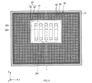
- the radar device 1 of the present embodiment shown in FIG. 1 is a device for measuring at least the distance to an object existing within a predetermined detection range by being mounted on a vehicle and transmitting/receiving target radio waves.
- the target radio wave is a radio wave in a predetermined frequency band, and for example, a millimeter wave is used. In this embodiment, millimeter waves with a frequency of 77 GHz band are used, but the frequencies used are not limited to this.
- the radar device 1 is fixed, for example, to a metal plate surface that is part of the body 9 of the vehicle, located inside the bumper 8 of the vehicle.
- the radar device 1 includes a lower case 31, a radome 32, a connector 33, a circuit board 34, and a radio wave suppressor .
- the lower case 31 is a box-shaped member made of a radio-impermeable material.
- the lower case 31 has a rectangular parallelepiped outer shape, and one surface is open.
- the radome 32 is a plate-shaped member made of a resin material that transmits radio waves.
- the radome 32 is provided at a position through which the target radio wave is transmitted. Radome 32 is attached to lower case 31 so as to close the opening of lower case 31 .
- the lower case 31 and the radome 32 form a space for housing the circuit board 34.
- the lower case 31 and the radome 32 are collectively called a housing.
- a connector 33 is provided on the side wall of the lower case 31 .
- the connector 33 is used to electrically connect an electronic circuit on the circuit board 34 (that is, a transmission/reception circuit section 342 to be described later) and a vehicle on which the radar device 1 is mounted.
- the circuit board 34 includes an antenna section 341 and a transmission/reception circuit section 342 .
- the antenna unit 341 is configured, for example, by arranging a plurality of patch antennas 343 in a two-dimensional array, and transmits and receives target radio waves.
- a surface on which the antenna portion 341 is formed is called an antenna surface 35 .
- the long side direction of the circuit board 34 is the x-axis direction
- the short side direction is the y-axis direction
- the axial direction perpendicular to the antenna surface 35 is the z-axis direction.
- the xyz three-dimensional coordinate axes are used as appropriate.
- the side on which the radiation wave is radiated with the antenna surface 35 as a boundary is the plus side of the z-axis
- the opposite side is the minus side of the z-axis.
- Arranging a plurality of patch antennas 343 in a two-dimensional array means that a plurality of patch antennas 343 are arranged two-dimensionally along the x-axis direction and the y-axis direction.
- a plurality of (for example, seven) patch antennas 343 arranged in a row along the y-axis direction are each formed into one array antenna (hereinafter referred to as a unit antenna 344 ). That is, as shown in FIGS. 3 and 4, the antenna section 341 has a structure in which a plurality of (eg, five) unit antennas 344 are arranged along the x-axis direction.
- the number of patch antennas 343 included in the unit antenna 344 and the number of unit antennas 344 included in the antenna section 341 are not limited to this.
- any one of the plurality of unit antennas 344 can be used as a transmitting antenna, and the others can be used as receiving antennas. That is, in the radar device 1, the direction of direction detection is the x-axis direction in which the unit antennas 344 are arranged.
- the aspect of the transmitting antenna and the receiving antenna is not limited to this, and the number and arrangement of the unit antennas 344 used as transmitting antennas and the unit antennas 344 used as receiving antennas can be set arbitrarily. . Also, all the unit antennas 344 may be used as transmitting antennas, or all the unit antennas 344 may be used as receiving antennas.
- the transmission/reception circuit section 342 includes a circuit that generates transmission signals to be supplied to the antenna section 341 according to commands input through the connector 33 .
- the transmitting/receiving circuit section 342 includes a circuit or the like that performs signal processing such as down-conversion on the received signal supplied from the antenna section 341 and outputs the processed signal through the connector 33 .
- the xyz-axis directions of the circuit board 34 are also applied to the radar device 1 in which the circuit board 34 is attached to the lower case 31 .
- the radar device 1 is fixed to the vehicle so that the y-axis direction coincides with the vehicle height direction, the x-axis direction coincides with the horizontal direction, and the z-axis direction coincides with the center direction of the detection area.
- the detection area is a predetermined angular range (hereinafter referred to as a predetermined (also called angular range ⁇ x).
- the predetermined angular range ⁇ x is set to -60° to +60°, for example.
- the predetermined angle range ⁇ x is not limited to ⁇ 60° to +60°, and may be set to a narrower angle than this, or may be set to a wider angle than this.
- the detection area is a predetermined angular range (hereinafter referred to as , a predetermined angular range ⁇ y).
- the predetermined angle range ⁇ y is set to be narrower than the predetermined angle range ⁇ x.
- the radome 32 has a radio wave suppressor 36 on the radome facing surface 321 as shown in FIGS.
- the radome facing surface 321 is a surface of the outer surface of the radome 32 that faces (that is, faces) the antenna surface 35 .
- the outer surface refers to the exposed surface.
- the outer surface that does not face the antenna surface 35 is called a radome non-facing surface 322 .
- the radio wave suppression unit 36 is provided within the detection outside area 40 on the radome facing surface 321 .
- the out-of-detection range area 40 is, as shown in FIG. 5, an area outside the range of the detection angle ⁇ of the antenna section 341 (that is, the detection area of the antenna section 341).
- ⁇ may be the above-described ⁇ x or ⁇ y.
- projection region 41 a region obtained by projecting the range of the detection angle ⁇ of the antenna unit 341 onto the radome-facing surface 321 (hereinafter, projection region 41) is within the range of the detection angle ⁇ of the antenna unit 341 on the radome-facing surface 321 (that is, the detection area). corresponds to the area of
- the out-of-detection-range area 40 refers to an area outside the projection area 41 on the radome-facing surface 321 .
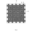
- the radio wave suppressor 36 is provided in substantially the entire detection range area 40 on the radome facing surface 321 .
- the radio wave suppression unit 36 controls the remaining area (hereinafter also referred to as the formation area 44) of the detection range area 40 except for the preliminary area 45 which is a predetermined distance dk away from the projection area 41. ).
- the forming region 44 is a region in which the radio wave suppressor 36 is provided (that is, formed) in the detection range outside region 40 .
- the predetermined length dk can be appropriately set to a length such that the radio wave suppressing section 36 does not affect the directivity of the antenna section 341 .
- the radio wave suppressing section 36 includes a conducting section 50 having conductivity and a non-conducting section 60 having no conductivity. Having conductivity here means that the conductivity is 1 S/m or more.
- the conductive portion 50 is a portion of the radome-facing surface 321 where the material of the radome 32 is changed.
- the conductive portion 50 has conductivity by changing the material of the radome 32 and is integrated with the radome 32 .
- a portion other than the conductive portion 50 in the radio wave suppression portion 36 is referred to as a non-conductive portion 60 .
- the part where the material of the radome 32 is changed is the part where the resin, which is the material of the radome 32, is carbonized.
- Resin can be changed in material so as to have conductivity by being carbonized by the application of heat.
- the electrical conductivity obtained by carbonizing the resin is about 10-100 S/m.
- Aromatic resin can be used as the resin as the material of the radome 32 .
- Examples include PBT (ie, polybutylene terephthalate), PPS (ie, polyphenylene sulfide), PI (ie, polyimide), phenol, and the like.
- the conductive portion 50 is a portion of the radome-facing surface 321 that has conductivity due to the carbonization of the resin that is the material of the radome 32.
- the resin is removed by irradiating the resin with a laser beam. Carbonize.
- the conductive portion 50 is formed by appropriately irradiating a laser beam onto a portion of the radome-facing surface 321 where unwanted waves, which will be described later, are desired to be suppressed (that is, here, substantially the entire area outside the detection range 40 of the radome-facing surface 321). be done.
- the radio wave suppressor 36 is integrated with the radome 32 .
- integrated refers to being formed as a part of the radome 32 (that is, integrally formed) without adding new parts to the radome 32 .
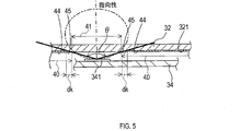
- the radio wave suppressor 36 includes a plurality of projections 70 having a shape projecting from the radome facing surface 321. As shown in FIG. The projecting portion 70 is made of the same material as the radome 32 . A remaining portion of the radio wave suppressing portion 36 excluding the protrusion 70 , that is, a remaining portion excluding the protrusion 70 from within the formation region 44 of the radome-facing surface 321 is referred to as a non-protruding portion 71 .
- Each protruding portion 70 has a substantially cubic shape, and the plurality of protruding portions 70 are arranged at a pitch interval P, which is a predetermined interval, along the x direction and the y direction. That is, the top surface 324, which is the surface of the protrusion 70 and faces in the direction of protrusion (that is, the -z direction), has a substantially square shape. Here, the length of one side of the top surface 324 (that is, the width D of the projecting portion 70) and the projecting height H of the projecting portion 70 from the radome-facing surface 321 are equal. Then, of the radio wave suppressing portion 36, the conductive portion 50 is formed on both the top surface 324 in the projecting direction (that is, the -z direction) and the non-projecting portion 71 on the surface of the projecting portion 70. .
- the conductive portion 50 has a substantially square shape, which is a predetermined shape, and has specific directions of x and y. can be said to be arranged at a pitch interval P, which is a predetermined interval.
- the specific direction is the direction in which the conductive portions 50 are arranged.
- the conductive portion 50 of the protruding portion 70 is formed by irradiating a substantially square laser beam in order at pitch intervals P along the x-direction or along the y-direction.
- the conductive portion 50 has a linear shape that is a predetermined shape, and along the specific directions of the x direction and the y direction, It can be said that they are arranged at predetermined intervals (that is, the width D of the projecting portion 70).
- the straight line referred to here means a straight line having a line width equal to the pitch interval P.
- the conductive portion 50 of the protruding portion 70 is formed by irradiating a linear laser beam having a line width of the pitch interval P in order for each width D of the protruding portion 70 along the x direction or along the y direction. It is formed. In other words, focusing on the non-protruding portion 71, the conductive portion 50 is formed in a grid pattern.
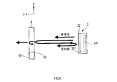
- radiation waves (hereinafter also referred to as direct waves) directly radiated from the radar device 1 (that is, the antenna section 341) are radiated to the outside of the radar device 1 via the radome 32.
- a portion of the direct wave can be reflected once by the bumper 8 or multiple-reflected between the bumper 8 and the radome 32 to become a reflected wave toward the radar device 1 or toward the bumper 8 .
- it is a part of the direct wave and is a reflected wave toward the radar device 1 due to reflection between the bumper 8 and the radome 32 (that is, a reflected wave toward the inside of the housing of the radar device 1) or a reflected wave toward the bumper 8.
- a wave is called an unwanted wave.
- Such unwanted waves may cause an error in direction detection by interfering with direct waves (that is, radar waves) radiated into the detection area outside and inside the radar device 1 .
- the projection height H of the projecting portion 70 in the radio wave suppressing portion 36 is set to ⁇ /4. Therefore, the reflected wave 101 from the conductive portion 50 of the projecting portion 70 and the reflected wave 102 from the conductive portion 50 of the non-projecting portion 71 are out of phase by nearly 180° and cancel each other. That is, the reflection characteristic of the target radio wave in the radome 32 (that is, the so-called S11 characteristic) has a relatively small value at the frequency of the target radio wave.
- the radio wave suppression unit 36 suppresses unnecessary waves traveling outside the radar device 1 (that is, traveling toward the bumper 8). This prevents the unnecessary waves from interfering with the direct waves radiated into the detection area due to multiple reflections with the bumper 8 and causing errors in the azimuth detection (that is, becoming interference waves). be done.
- both the top surface 324 of the protruding portion 70 and the non-protruding portion 71 have the conductive portion 50, so that reflected waves from the bumper 8 toward the radome 32 enter the housing. Hard to penetrate. This is because reflected waves from the bumper 8 toward the radome 32 can only pass through the side surfaces of the projecting portion 70 excluding the top surface 324 into the housing. For example, among the reflected waves 103 to 105 shown in FIG. 9, the reflected wave 105 is transmitted into the housing, but the reflected waves 103 to 104 are reflected by the conductive portion 50 and cannot be transmitted into the housing.
- waves other than reflected waves eg, reflected waves 105 directed from the bumper 8 toward the radome 32 at a certain angle cannot be transmitted into the housing.
- the transmission characteristic of the target radio wave in the radome 32 (that is, the so-called S21 characteristic) has a relatively small value.
- the radio wave suppression unit 36 suppresses unnecessary waves traveling toward the inside of the radar device 1 (that is, from the bumper 8).
- the unwanted wave interferes with the direct wave radiated within the detection area due to multiple reflection or the like in the radar device 1, causing an error in azimuth detection (that is, becoming an interference wave). is suppressed.
- the radio wave suppression unit 36 is integrated with the radome 32, and as a result, acts to suppress the influence of unwanted waves on the azimuth detection error of an object, like a so-called absorption element that absorbs electromagnetic waves.
- the radio wave suppressor 36 is integrated with the radome 32 in the detection range outside region 40 of the radome facing surface 321 of the radome 32, and the conductive portion 50 and the non-conductive portion 60.
- the radio wave suppression unit 36 suppresses unnecessary waves directed to the outside of the radar device 1 and unwanted waves directed to the inside of the radar device 1, these unnecessary waves interfere with the direct waves radiated within the detection area, resulting in an error in direction detection. can be suppressed. Moreover, since there is no need to newly install an absorbing element, it is possible to reduce manufacturing costs and azimuth detection errors that may occur due to variations in installation accuracy when installing the absorbing elements.
- the radar device 1 can solve the problems that may occur when installing the absorbing element, and reduce the azimuth detection error by the radar device 1 .
- the weight of the radar device 1 can be reduced, and the thickness of the radar device 1 can be reduced (that is, z direction) can be achieved. In this way, the radar device 1 can solve the problem that may occur when installing the absorbing element, and reduce the azimuth detection error by the radar device 1 .
- the conductive portion 50 is a portion where the material of the radome 32 is changed.
- the portion where the material has changed specifically means a portion where the material is carbonized.
- part of the radome 32 is used as the conductive portion 50 (that is, the radio wave suppression portion 36), so that manufacturing costs can be further reduced.
- the radar device 1 can be made lighter and thinner.
- the radio wave suppressor 36 has the conductive portions 50 having a predetermined shape and arranged at predetermined intervals along a predetermined specific direction. . That is, the conductive portions 50 are arranged with periodicity in a specific direction. Accordingly, by appropriately setting the shape, spacing, etc. of the conductive portions 50, the unwanted waves can be in opposite phases and can be canceled and attenuated more than when the conductive portions 50 are arranged without periodicity. can enhance sexuality. As a result, the direction detection error by the radar device 1 can be suppressed. In addition, since the conductive portions 50 are arranged with periodicity, the work efficiency in carbonizing by irradiating the laser light can be improved as compared with the case where the conductive portions 50 are arranged without periodicity.
- the radio wave suppressor 36 includes the projecting portion 70 and the non-projecting portion 71, and the projecting portions 70 are arranged at predetermined intervals along the specific direction, and project At least one of the surface of the portion 70 and the non-projecting portion 71 is provided with the conductive portion 50 . Accordingly, by appropriately setting the projection height H of the projecting portion 70, it is possible to increase the possibility that the unwanted waves will have opposite phases and cancel each other out and be attenuated. Further, since the radio wave suppressing portion 36 includes the conductive portion 50 on at least one of the surface of the protruding portion 70 and the non-protruding portion 71, unwanted waves can be attenuated. As a result, the azimuth detection error of the radar device 1 can be suppressed.
- the radio wave suppressor 36 includes the conductive portion 50 on both the surface of the non-protruding portion 71 and the protruding portion 70 .
- the radio wave suppressing portion 36 includes more conductive portions 50 than when one of the protruding portion 70 and the non-protruding portion 71 is provided with the conductive portion 50, so that unnecessary waves can be more attenuated.
- the azimuth detection error of the radar device 1 can be further suppressed.
- the protrusion height H of the protrusion 70 is an odd multiple of ⁇ /4.
- the protrusion height H of the protrusion 70 is not an odd multiple of ⁇ /4, it is possible to further increase the possibility that the unwanted waves will have opposite phases and cancel each other out and be attenuated.
- the azimuth detection error of the radar device 1 can be further suppressed.
- the interval between the adjacent protrusions 70 (that is, the pitch width P) is an odd multiple of ⁇ /4 in a specific direction. This makes it possible to increase the possibility that unwanted waves (e.g., unwanted waves that propagate particularly in a specific direction) will have opposite phases, cancel each other out, and be attenuated. As a result, the azimuth detection error of the radar device 1 can be further suppressed.
- the specific direction in which the conductive portions 50 are arranged with regularity includes the x-direction and the y-direction perpendicular to the x-direction.
- the conductive portions 50 are arranged perpendicular to each other in a grid pattern. are arranged in As a result, the conductive portions 50 are perpendicular to each other, so that it is possible to further improve the work efficiency when irradiating and carbonizing the laser beam.
- the radome 32 corresponds to the cover portion
- the unit antenna 344 corresponds to the antenna
- the radome facing surface 321 corresponds to the outer surface of the cover portion.
- a substantially square having a side length of D corresponds to a predetermined shape
- the x direction and the y direction correspond to specific directions
- the pitch interval P corresponds to a predetermined interval.
- a straight line having a line width equal to the pitch interval P corresponds to a predetermined shape
- the x direction and the y direction correspond to specific directions
- the width D corresponds to a predetermined interval.
- the x direction corresponds to the first direction
- the y direction corresponds to the second direction.
- Modification 1 Since Modification 1 has the same basic configuration as the above-described embodiment, differences will be described below. The same reference numerals as in the above-described embodiment indicate the same configuration, and the preceding description is referred to.
- the radome 32 is provided with a radio wave suppressor 36a. As shown in FIG. 10 , the radio wave suppressor 36 a does not have the projecting portion 70 .
- the radio wave suppressing portion 36a is provided on the radome-facing surface 321 of the radome 32 with a conductive portion 50 having a linear shape with a line width equal to the pitch interval P described above and having a width D described above along the x and y directions. Arranged by intervals. That is, in the radio wave suppressing portion 36a, the conductive portions 50 are arranged perpendicular to each other in a grid pattern. This makes it possible to obtain the same effects as (1a)-(1c) and (1h) described above.
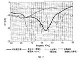
- FIG. 12 shows the result of calculating S11 in the range of 60 GHz to 90 GHz based on the signal acquired by the antenna section 341 by simulation.
- a thick solid line is the embodiment of the present disclosure, a thin solid line is Modification 1, a short dashed line is Comparative Example 1 described later, and a long dashed line is Comparative Example 2 described later.
- a radio wave absorber 201 that is, an absorption element .
- PBT mixed with carbon fiber as a filler was used.
- the radio wave suppressing portion 36a is formed by two-color molding so that the same area as the formation area 44 of the radome 32 is made of PBT mixed with carbon fiber as a filler, and the remaining portion is made of carbon fiber as a filler. It was formed by unmixed PBT as
- the radome 32 was formed using PBT.
- the projecting portion 70 and the non-projecting portion 71 similar to the radio wave suppressing portion 36 of the embodiment of the present disclosure are formed in the radome 32, and both the projecting portion 70 and the non-projecting portion 71 form the conductive portion 50.
- the configuration is not prepared.
- Modification 1 is, as described above, a conductive portion 50 having a linear shape with a line width equal to the pitch interval P in the radome 32 formed of PBT in a plate shape without forming the projecting portion 70 , and extending in the x direction. and arranged at intervals of width D along the y direction.
- S11 is smaller than Comparative Examples 1 and 2 (that is, the reflected wave is greatly suppressed), especially near the frequency of the target radio wave (that is, 77 GHz). .
- the above-described unnecessary waves which may be reflected by the radome 32 and directed toward the bumper 8, are greatly suppressed.
- FIG. 13 shows the result of calculating S21 in the range of 60 GHz-90 GHz based on the signal acquired by the antenna section 341 through simulation.
- S21 is about the same as or smaller than Comparative Example 1 (that is, the transmitted wave is greatly suppressed) in almost the entire range of 60 GHz-90 GHz.
- unnecessary waves which may cause reflection waves from the bumper 8 to pass through the radome 32 and be multiple-reflected inside the housing, are suppressed to the same extent as in the first comparative example or more.
- S21 is approximately the same as in Comparative Example 1.
- unnecessary waves which may cause reflected waves from the bumper 8 to pass through the radome 32 and be reflected within the housing, are suppressed to the same extent as in the first comparative example.
- the radio wave suppressing portion 36 of the present disclosure and the radio wave suppressing portion 36a of Modification 1 are parts integrated with the radome 32, and are equivalent to or more than Comparative Example 1 (that is, the absorbing element) ( In other words, it can be seen that this is a portion that can largely suppress unnecessary waves.
- the radio wave suppressing unit 36 of the present disclosure and the radio wave suppressing unit 36a of Modification 1 have the effect of suppressing direction detection errors.
- the radio wave suppression unit 36 of the embodiment of the present disclosure has a greater effect of suppressing the azimuth detection error than the first modification.
- the radio wave suppressing portions 36 and 36a are insulated by covering at least the conductive portion 50 with a film or coating, an adhesive, or an adhesive sheet. It may be configured as As a result, the conductive portion 50 is insulated, and peeling of the carbonized resin from the conductive portion 50 can be suppressed.
- the film is desirably the same material as the material of the radome 32, for example, from the viewpoint of suppressing peeling due to the difference in linear expansion and from the viewpoint of cost reduction due to process integration. However, it is not necessarily the same material as the material of the radome 32, and acrylic, PET (that is, polyethylene terephthalate), PC (that is, polycarbonate), etc. can be used.
- the conductive portions 50 having a linear shape with a line width of the pitch interval P are spaced apart by a width D along the x direction and the y direction. , but the line width may not be constant. Also, the intervals may not be constant.
- the conductive portion 50 has a predetermined shape and extends along at least one predetermined specific direction. Multiple arrays are arranged at intervals.
- the predetermined shape can be linear, circular, polygonal, elliptical, and various other shapes.
- the specific direction may be a direction in which the direction can be detected by the antenna unit 341 or any other direction.
- the specific direction may be one direction or multiple directions. Moreover, when there are a plurality of specific directions, these directions may or may not be orthogonal to each other.
- the intervals at which they are arranged may be predetermined constant intervals, or may not be predetermined constant intervals.
- the projection heights H of all the projections 70 in the radio wave suppression units 36 and 36a may not be uniform.
- the intervals between all the protruding portions 70 may not be uniform.
- the projection height H or the pitch interval P of the projections 70 may be different depending on the position of the projections 70 depending on the frequency of unwanted waves to be suppressed.
- the shape of the projecting portion 70 is not limited to a cube, and may be any shape such as a column, a polygonal column, or the like.
- the conductive portion 50 can be formed only in the protruding portion 70 of the protruding portion 70 and the non-protruding portion 71 in the radio wave suppression portion 36 .
- the conductive portion 50 may be formed only on the non-protruding portion 71 .
- the conductive section 50 may be formed on the side surface of the protruding section 70 in addition to the top surface 324 .
- the radio wave suppressing portion 36 has a stepped portion that is similar to the projecting portion 70 and arranged in a plurality of steps along the z-axis direction, such as two steps, three steps, and so on. can have the shape Then, the conductive portion 50 can be formed on the top surfaces of the first stage, second stage, third stage, and so on (that is, the surface in the -z direction, which is the projecting direction).
- the thickness of the conductive portion 50 may not be uniform in the radio wave suppression portions 36 and 36a.
- the greater the thickness of the carbonized portion the greater the electrical conductivity.
- the thickness of the conductive portion 50 may be made larger than the thickness of the conductive portion 50 provided in other portions.
- the radio wave suppression units 36 and 36a may be provided over the entire detection range area 40 of the radome facing surface 321 .
- the radio wave suppression units 36 and 36a may be provided in predetermined arbitrary regions of the detection range outside region 40 of the radome facing surface 321 .
- the radio wave suppression units 36 and 36a may be provided at one location or at a plurality of locations in the out-of-detection-range region 40 of the radome-facing surface 321 .
- the size of the region in which the radio wave suppressors 36 and 36a are provided may be any predetermined size.
- the radio wave suppression units 36 and 36a may be provided on the radome non-facing surface 322 as shown in FIG.
- FIG. 14 shows the forming region 44 on the radome non-facing surface 322 .
- the formation region 44 may be provided with either the radio wave suppressor 36 or 36a.
- the radome 32 corresponds to the cover portion
- the radome non-facing surface 322 corresponds to the outer surface of the cover portion.
- At least one of the radome 32, the bumper 8, and the emblem may be provided with the radio wave suppression units 36 and 36a.
- the radio wave suppressing portions 36, 36a are, as shown in FIGS. 15 and 16, the surfaces of the outer surface of the bumper 8a facing the antenna surface 35 (that is, the surfaces facing the radar device 1). It may be provided on the bumper facing surface 81 .
- the bumper 8a corresponds to the cover portion
- the bumper facing surface 81 corresponds to the outer surface of the cover portion.
- the radio wave suppression units 36 and 36a are the surfaces of the bumper 8a shown in FIGS. It may be provided on face 82 .
- the bumper 8a corresponds to the cover portion
- the non-bumper facing surface 82 corresponds to the outer surface of the cover portion.
- the bumper 8a in FIGS. 15 and 16 may be replaced with the emblem of the vehicle.
- the radio wave suppressor 36, 36a may be provided on the outer surface of the emblem facing the antenna surface 35 (that is, the radar device 1).
- the emblem corresponds to the cover portion
- the surface of the emblem facing the antenna surface 35 corresponds to the outer surface of the cover portion.
- the radio wave suppressor 36 may be provided on a surface of the emblem attached to the vehicle that does not face the antenna surface 35 (that is, the radar device 1).
- the emblem corresponds to the cover portion
- the surface of the emblem that does not face the antenna surface 35 corresponds to the outer surface of the cover portion.
- the conductive unit 50 is integrated with the radome 32 by vapor-depositing metal (for example, aluminum) on the radome 32 so as to have conductivity. may be formed in Alternatively, the conductive portion 50 may be integrated with the radome 32 by adhering a metal thin film to the radome 32 with an adhesive or the like so as to be conductive.
- the resin that is the material of the radome 32 a resin obtained by mixing the resin described above with a filler (that is, a filler) may be used.
- a filler a material that increases the strength of the resin when mixed with it and becomes electrically conductive when heat is applied can be used.
- glass fibers are used as fillers.
- aramid fiber, asbestos fiber, gypsum fiber, silica fiber, silica-alumina fiber, alumina fiber, zirconia fiber, silicon nitride fiber, silicon fiber, potassium titanate fiber and the like can be used.
- the above-described radar device 1 may be configured so that the y-axis direction as well as the x-axis direction is used as the azimuth detection direction.
- the plurality of patch antennas 343 can be arranged in the antenna section 341 in the same manner as in the above embodiments.
- the antenna unit 341 can not only detect the azimuth in the x-axis direction by using the same method as in the above-described embodiment, but also includes an array antenna having a plurality of patch antennas 343 arranged in a line along the x-axis as a unit antenna. , it may be possible to detect the azimuth in the y-axis direction. According to such a radar device 1, it is possible to obtain the effect of suppressing azimuth detection errors not only in the x-axis direction but also in the y-axis direction.
- the transmitting/receiving circuit section 342 may be arranged on the opposite side of the antenna surface 35 of the circuit board 34, or may be arranged outside the lower case 31 so as to be connected to the antenna section 341 of the circuit board 34. It may be connected by a cable or the like (not shown).
- the radome 32 may have a rectangular parallelepiped outer shape and a box shape with one side open. That is, the radome 32 has a tubular portion having a rectangular tubular shape and a plate-shaped portion arranged so as to close one opening of the tubular portion, and the radio wave suppressor 36 is provided in the plate-shaped portion. You may prepare.
- a housing may be formed by the radome 32 and the lower case 31 as described above.
Landscapes
- Engineering & Computer Science (AREA)
- Radar, Positioning & Navigation (AREA)
- Remote Sensing (AREA)
- Physics & Mathematics (AREA)
- Computer Networks & Wireless Communication (AREA)
- General Physics & Mathematics (AREA)
- Electromagnetism (AREA)
- Computer Security & Cryptography (AREA)
- Radar Systems Or Details Thereof (AREA)
- Aerials With Secondary Devices (AREA)
- Variable-Direction Aerials And Aerial Arrays (AREA)
- Details Of Aerials (AREA)
Abstract
レーダ装置(1)は、アンテナ部(341)と、カバー部(32、8)と、電波抑制部(36)と、を備える。アンテナ部は、電波を放射する1つ以上のアンテナが設置されたアンテナ面(35)を含み、予め定められた周波数帯の対象電波を照射するように構成される。カバー部は、対象電波が透過する位置に設けられるように構成される。電波抑制部は、カバー部の外面のうち、アンテナ部の検知角度の範囲外の領域である検知範囲外領域(40)にカバー部と一体化され、導電性を有する導電化部(50)と、導電性を有しない非導電化部(60)と、を含む。
Description
本国際出願は、2021年4月27日に日本国特許庁に出願された日本国特許出願第2021-74842号に基づく優先権を主張するものであり、日本国特許出願第2021-74842号の全内容を本国際出願に参照により援用する。
本開示は、レーダ装置に関する。
車両の自動運転や衝突防止などを目的として使用されるミリ波レーダが知られている。ミリ波レーダは、電波を照射し、照射した電波が物体にて反射した反射波を検出して、所定の検知エリア内における物体の存在やその物体までの距離を検知するためのレーダである。
ミリ波レーダの性能は、車両に搭載して評価すると、レーダ単体で評価したときと比較して劣化する。性能の劣化は、検知エリアから外れたり意図しない領域に回り込んだりした電波である不要波が、干渉波となってレーダ波の位相を乱し、物体の方位検知に誤差を生じさせることによって生じる。主要な不要波としては、例えば、バンパからの反射波が知られている。
特許文献1には、レーダ装置内に、電磁波を吸収する材料にて形成された吸収要素を設けることで、不要波による影響を抑制する技術が開示されている。
上述した特許文献1に記載のレーダ装置では、吸収要素を新たな部品として設置する必要があるため、製造のためのコストが上昇するという問題が見出された。また、吸収要素を設置する際の設置精度のばらつきが、物体の方位検知に誤差を生じさせる要因となる、という新たな課題も見出された。
本開示の一態様では、吸収要素を設置する際に生じ得る課題を解決し、レーダ装置による方位検知誤差を低減する技術を提供する。
本開示の一態様は、レーダ装置であって、アンテナ部と、カバー部と、電波抑制部と、を備える。アンテナ部は、電波を放射する1つ以上のアンテナが設置されたアンテナ面を含み、予め定められた周波数帯の対象電波を照射するように構成される。カバー部は、対象電波が透過する位置に設けられるように構成される。電波抑制部は、カバー部の外面のうち、アンテナ部の検知角度の範囲外の領域である検知範囲外領域にカバー部と一体化され、導電性を有する導電化部と導電性を有しない非導電化部と、を含む。
このような構成によれば、電波抑制部はレーダ装置外へ向かう不要波及びレーダ装置内へ向かう不要波を抑制するので、これらの不要波が検知エリア内に放射される直接波と干渉することによって方位検知に誤差を生じさせること、を抑制することができる。また、吸収要素を新たに設置する必要がないため、製造のためのコストも、吸収要素を設置する際の設置精度のばらつきに基づいて生じ得る方位検知誤差も、抑制することができる。つまり、吸収要素を設置する際に生じ得る課題を解決し、レーダ装置による方位検知誤差を低減することができる。
以下、図面を参照しながら、本開示の実施形態を説明する。なお、以下でいう「垂直」とは、厳密な意味での垂直に限るものではなく、同様の効果を奏するのであれば厳密に垂直でなくてもよい。「奇数倍」、「等しい」についても同様である。
[実施形態]
[1.構成]
以下、本開示の例示的な実施形態について図面を参照しながら説明する。
[1.構成]
以下、本開示の例示的な実施形態について図面を参照しながら説明する。
図1に示す本実施形態のレーダ装置1は、車両に搭載され、対象電波を送受信することにより、予め定められた検知範囲内に存在する物体との距離を少なくとも測定するための装置である。対象電波は、あらかじめ定められた周波数帯の電波であり、例えばミリ波が用いられる。本実施形態では、77GHz帯を周波数とするミリ波が用いられるが、使用される周波数はこれに限定されるものではない。
レーダ装置1は、例えば、車両のバンパ8の内側に位置する、車両のボディ9の一部である金属製の板面に固定される。
図2-図4に示すように、レーダ装置1は、ロアケース31と、レドーム32と、コネクタ33と、回路基板34と、電波抑制部36と、を備える。
ロアケース31は、電波を非透過とする材料で形成された箱状の部材である。ロアケース31は、直方体状の外形に形成されており、1つの面が開口している。
レドーム32は、電波を透過する樹脂材料で形成された板状の部材である。レドーム32は、対象電波が透過する位置に設けられている。レドーム32は、ロアケース31の開口を塞ぐようにロアケース31に取り付けられる。
ロアケース31及びレドーム32は、回路基板34を収納する空間を形成する。ロアケース31及びレドーム32を併せて筐体ともいう。
ロアケース31の側壁には、コネクタ33が設けられる。コネクタ33は、回路基板34上の電子回路(すなわち、後述する送受信回路部342)と当該レーダ装置1を搭載する車両とを電気的に接続するために用いられる。
回路基板34は、アンテナ部341と、送受信回路部342とを備える。
アンテナ部341は、例えば、複数のパッチアンテナ343を2次元アレイ状に配置することで構成され、対象電波を送受信する。アンテナ部341が構成された面をアンテナ面35という。
ここで、回路基板34の長辺方向をx軸方向、短辺方向をy軸方向とし、アンテナ面35に対して垂直な軸方向をz軸方向とする。以下では、このxyz三次元座標軸を適宜用いて説明する。但し、アンテナ面35を境界として放射波が放射される側がz軸のプラス側であり、その反対側がz軸のマイナス側である。
複数のパッチアンテナ343を2次元アレイ状に配置するとは、x軸方向及びy軸方向に沿ってそれぞれ複数個のパッチアンテナ343が2次元的に配列されることをいう。
ここでは、図2、図4に示すように、y軸方向に沿って1列に配置された複数(例えば、7個)のパッチアンテナ343が、それぞれ、一つのアレーアンテナ(以下、単位アンテナ344)として機能するように構成される。つまり、アンテナ部341は、図3、図4に示すように、複数(例えば、5個)の単位アンテナ344がx軸方向に沿って配列された構造である。但し、単位アンテナ344に含まれるパッチアンテナ343の数、及びアンテナ部341に含まれる単位アンテナ344の数は、これに限定されるものではない。
複数の単位アンテナ344は、例えば、いずれか1つが送信アンテナとして使用され、それ以外は受信アンテナとして使用され得る。つまり、レーダ装置1では、単位アンテナ344の配列方向であるx軸方向が方位検知方向となる。但し、送信アンテナ及び受信アンテナの態様はこれに限定されるものではなく、送信アンテナとして使用される単位アンテナ344、及び受信アンテナとして使用される単位アンテナ344の数及び配置は、任意に設定され得る。また、すべての単位アンテナ344が送信アンテナとして使用されてもよいし、すべての単位アンテナ344が受信アンテナとして使用されてもよい。
送受信回路部342は、コネクタ33を介して入力される指令に従って、アンテナ部341に供給する送信信号を生成する回路を含む。また送受信回路部342は、アンテナ部341から供給される受信信号をダウンコンバート等の信号処理をしてコネクタ33を介して出力する回路等を含む。
以下では、回路基板34がロアケース31に取り付けられたレーダ装置1に対しても、回路基板34のxyz軸方向を適用する。ここでは、レーダ装置1は、y軸方向が車高方向と一致し、x軸方向が水平方向と一致し、z軸方向が検知エリアの中心方向と一致するように車両に固定される。
検知エリアは、図3に示すように、アンテナ面35の中央を原点として、x-z平面内においてアンテナ面35の法線方向、すなわちz軸方向を0°とする所定角度範囲(以下、所定角度範囲θxともいう)のエリアを含む。所定角度範囲θxは、例えば、-60°~+60°に設定される。但し、所定角度範囲θxは-60°~+60°に限定されるものではなく、これよりも狭角に設定されてもよいし、これよりも広角に設定されてもよい。
また、検知エリアは、図2に示すように、アンテナ面35の中央を原点として、y-z平面内においてアンテナ面35の法線方向、すなわちz軸方向を0°とする所定角度範囲(以下、所定角度範囲θyともいう)のエリアを含む。所定角度範囲θyは、所定角度範囲θxよりも狭角に設定される。
レドーム32は、電波抑制部36を、レドーム対向面321に、図2-図4に示すように備える。レドーム対向面321は、レドーム32における外面のうち、アンテナ面35に対向する(すなわち、向かい合う)面である。外面とは、露出する面をいう。なお、レドーム32における外面のうち、アンテナ面35に対向しない外面をレドーム非対向面322という。
詳しくは、電波抑制部36は、レドーム対向面321における検知範囲外領域40内に備えられる。検知範囲外領域40とは、図5に示すように、アンテナ部341の検知角度θの範囲(すなわち、アンテナ部341の検知エリア)外の領域である。ここでいうθは上述のθxであってもよいしθyであってもよい。例えば、アンテナ部341の検知角度θの範囲をレドーム対向面321に投影した領域(以下、投影領域41)が、レドーム対向面321におけるアンテナ部341の検知角度θの範囲(すなわち、検知エリア)内の領域に相当する。
つまり、検知範囲外領域40とは、レドーム対向面321における投影領域41外の領域をいう。ここでは、電波抑制部36は、図4に示すように、レドーム対向面321における、検知範囲外領域40のほぼ全域に備えられる。具体的には、電波抑制部36は、検知範囲外領域40のうち、投影領域41から予め定められた所定長さdk離れた予備領域45を除いた残りの領域(以下、形成領域44ともいう)に備えられる。形成領域44とは、検知範囲外領域40のうちの電波抑制部36が備えられる(すなわち、形成される)領域をいう。所定長さdkは、電波抑制部36がアンテナ部341の指向性に影響を与えない程度の長さに、適宜設定され得る。
電波抑制部36は、図6及び図7に示すように、導電性を有する導電化部50と、導電性を有しない非導電化部60と、を含む。ここでいう導電性を有するとは、導電率が1S/m以上であることをいう。導電化部50は、レドーム対向面321において、レドーム32の材質を変化させた部分である。導電化部50は、レドーム32の材質を変化させることにより導電性を有し、且つ、レドーム32と一体化される。電波抑制部36において導電化部50以外の残りの部分を非導電化部60という。
レドーム32の材質を変化させた部分、とは具体的には、レドーム32の材料である樹脂を炭化させた部分、である。樹脂は、熱が加えられて炭化することによって、導電性を有するように、材質が変化し得る。なお、樹脂を炭化することにより得られる導電率は、約10-100S/mである。
レドーム32の材料としての樹脂は、芳香族系の樹脂が用いられ得る。例えば、PBT(すなわち、ポリブチレンテレフタラート)、PPS(すなわち、ポリフェニレンサルファイド)、PI(すなわち、ポリイミド)、フェノール等が含まれる。
つまり、導電化部50は、レドーム対向面321において、レドーム32の材料である樹脂が炭化したことにより導電性を有する部分であり、具体的には、樹脂にレーザ光を照射することによって樹脂を炭化させる。導電化部50は、レドーム対向面321において、後述する不要波を抑制したい箇所(すなわち、ここではレドーム対向面321における検知範囲外領域40のほぼ全域)に、レーザ光を適宜照射することによって形成される。このようにして、電波抑制部36は、レドーム32と一体化される。ここでいう一体化されるとは、レドーム32に新たな部品を追加すること無く、レドーム32の一部として形成されること(すなわち、一体に形成されること)をいう。
レーダ装置1では、図7に示すように、電波抑制部36は、レドーム対向面321から突出する形状を有する複数の突出部70を備える。突出部70は、レドーム32と同じ材料により形成される。電波抑制部36のうち、突出部70を除いた残りの部分、すなわち、レドーム対向面321における形成領域44内から突出部70を除いた残りの部分を非突出部71という。
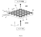
それぞれの突出部70は、略立方体の形状を有し、複数の突出部70は、x方向及びy方向に沿って、予め定められた間隔であるピッチ間隔Pで配列される。つまり、突出部70の表面であって突出する方向(すなわち、-z方向)における面である天面324は、略正方形の形状を有する。ここでは、天面324の一辺の長さ(すなわち、突出部70の幅D)、及び突出部70のレドーム対向面321からの突出高さHは等しい。そして、電波抑制部36のうち、突出部70の表面であって突出する方向(すなわち、-z方向)における天面324、及び、非突出部71の両方に、導電化部50が形成される。
ここで、電波抑制部36では、突出部70の天面324に着目すると、導電化部50は、予め定められた形状である略正方形の形状を有し、特定方向であるx方向及びy方向に沿って、予め定められた間隔であるピッチ間隔Pで配列されている、といえる。特定方向は、導電化部50が配列される方向である。突出部70の導電化部50は、x方向に沿ってまたはy方向に沿って、ピッチ間隔P毎に順に、略正方形にレーザ光を照射することにより形成される。
一方、電波抑制部36では、非突出部71に着目すると、導電化部50は、予め定められた形状である直線状の形状を有し、特定方向であるx方向及びy方向に沿って、予め定められた間隔(すなわち、突出部70の幅D)で配列されている、といえる。ここでいう直線とは、ピッチ間隔Pを線幅とする直線をいう。突出部70の導電化部50は、x方向に沿ってまたはy方向に沿って、突出部70の幅D毎に順に、ピッチ間隔Pを線幅とする直線状にレーザ光を照射することにより形成される。つまり、非突出部71に着目すると、導電化部50が格子状に形成される。
ここで、アンテナ部341が送受信する対象電波の波長をλとして、突出部70のレドーム対向面321からの突出高さHは、H=λ/4に設定される。但し、厳密にH=λ/4である必要はなく、例えば±25%以内程度のずれがあってもよい。なお、突出高さHは、λ/4の奇数倍であればよい。奇数は、2n+1(但し、nは整数)で表される。
また、突出部70の幅Dは、D=λ/4に設定される。但し、厳密にD=λ/4である必要はなく、例えば±25%以内程度のずれがあってもよい。なお、突出部70の幅Dは、λ/4の奇数倍であればよい。
また、突出部70の間隔であるピッチ間隔Pは、P=λ/4に設定される。但し、厳密にP=λ/4である必要はなく、例えば±25%以内程度のずれがあってもよい。なお、ピッチ間隔Pは、λ/4の奇数倍であればよい。
[2.作用]
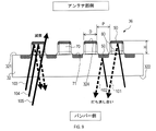
車両では、図8に示すように、レーダ装置1(すなわち、アンテナ部341)から直接放射された放射波(以下、直接波ともいう)は、レドーム32を介してレーダ装置1外部に放射される。直接波の一部は、バンパ8にて1回反射され、または、バンパ8とレドーム32との間で多重反射され、レーダ装置1へ向かう反射波またはバンパ8へ向かう反射波となり得る。ここでは、直接波の一部であって、バンパ8とレドーム32との間の反射によってレーダ装置1へ向かう反射波(すなわち、レーダ装置1の筐体内へ向かう反射波)またはバンパ8へ向かう反射波を、不要波という。このような不要波は、レーダ装置1外及びレーダ装置1内において、検知エリア内に放射される直接波(すなわち、レーダ波)と干渉することによって、方位検知に誤差を生じさせるおそれがある。
車両では、図8に示すように、レーダ装置1(すなわち、アンテナ部341)から直接放射された放射波(以下、直接波ともいう)は、レドーム32を介してレーダ装置1外部に放射される。直接波の一部は、バンパ8にて1回反射され、または、バンパ8とレドーム32との間で多重反射され、レーダ装置1へ向かう反射波またはバンパ8へ向かう反射波となり得る。ここでは、直接波の一部であって、バンパ8とレドーム32との間の反射によってレーダ装置1へ向かう反射波(すなわち、レーダ装置1の筐体内へ向かう反射波)またはバンパ8へ向かう反射波を、不要波という。このような不要波は、レーダ装置1外及びレーダ装置1内において、検知エリア内に放射される直接波(すなわち、レーダ波)と干渉することによって、方位検知に誤差を生じさせるおそれがある。
レーダ装置1では、図9に示すように、電波抑制部36にて突出部70の突出高さHがλ/4に設定されている。このため、突出部70が有する導電化部50での反射波101と、非突出部71が有する導電化部50での反射波102とは、位相が180°近くずれ、互いに打ち消しあう。つまり、レドーム32における対象電波の反射特性(すなわち、いわゆるS11特性)は、対象電波の周波数において相対的に小さい値となる。
このように、バンパ8からレドーム32へ向かう反射波の一部は、突出部70及び非突出部71が有する導電化部50により互いに打ち消し合うので、レドーム32にて反射され再びバンパ8に向かう反射波が抑制される。したがって、電波抑制部36によって、レーダ装置1外へ向かう(すなわち、バンパ8へ向かう)不要波が抑制される。これにより、該不要波が、バンパ8との多重反射等によって、検知エリア内に放射される直接波と干渉して方位検知に誤差を生じさせること(すなわち、干渉波となること)、が抑制される。
また、レーダ装置1では、図9に示すように、突出部70の天面324及び非突出部71の両方が導電化部50を有するので、バンパ8からレドーム32へ向かう反射波は筐体内へ透過し難い。バンパ8からレドーム32へ向かう反射波は、突出部70における天面324を除く側面からしか筐体内へ透過できないため、である。例えば、図9に示す反射波103-反射波105のうち、反射波105は筐体内へ透過するが、反射波103-104は導電化部50にて反射され筐体内へ透過できない。
換言すれば、ある特定の角度でバンパ8からレドーム32へ向かう反射波(例えば、反射波105)以外は、筐体内へ透過できない。レドーム32における対象電波の透過特性(すなわち、いわゆるS21特性)は、相対的に小さい値となる。このように、バンパ8からレドーム32へ向かう反射波の一部は、突出部70及び非突出部71が有する導電化部50により減衰されて筐体内へ透過する。したがって、電波抑制部36によって、レーダ装置1内へ向かう(すなわち、バンパ8からの)不要波が抑制される。これにより、該不要波が、レーダ装置1内での多重反射等によって、検知エリア内に放射される直接波と干渉して方位検知に誤差を生じさせること(すなわち、干渉波となること)、が抑制される。
つまり、電波抑制部36はレドーム32と一体化され、結果として、電磁波を吸収するいわゆる吸収要素と同様に、不要波による物体の方位検知誤差への影響を抑制するように作用する。
[3.効果]
以上詳述した実施形態によれば、以下の効果を奏する。
以上詳述した実施形態によれば、以下の効果を奏する。
(3a)レーダ装置1によれば、電波抑制部36は、レドーム32のレドーム対向面321のうちの検知範囲外領域40においてレドーム32と一体化されており、導電化部50と非導電化部60とを含む。
電波抑制部36はレーダ装置1外へ向かう不要波及びレーダ装置1内へ向かう不要波を抑制するので、これらの不要波が検知エリア内に放射される直接波と干渉することによって方位検知に誤差を生じさせること、を抑制することができる。また、吸収要素を新たに設置する必要がないため、製造のためのコストも、吸収要素を設置する際の設置精度のばらつきに基づいて生じ得る方位検知誤差も、抑制することができる。
つまり、吸収要素を設置する際に生じ得る課題を解決し、レーダ装置1による方位検知誤差を低減することができる。また、吸収要素等をレドーム32と別に(例えば、回路基板34上に)新たに設置する必要がないため、レーダ装置1の軽量化を図ることができ、レーダ装置1の薄型化(すなわち、z方向の厚さを薄くすること)を図ることができる。このように、レーダ装置1では、吸収要素を設置する際に生じ得る課題を解決し、レーダ装置1による方位検知誤差を低減することができる。
(3b)レーダ装置1によれば、導電化部50は、レドーム32の材質が変化した部分である。材質が変化した部分とは、具体的には、材料が炭化した部分をいう。これにより、レドーム32の一部が導電化部50(すなわち、電波抑制部36)とされるので、製造のためのコストをより低減することができる。また、レーダ装置1をより軽量化し、より薄型化することができる。
(3c)レーダ装置1によれば、電波抑制部36は、導電化部50が、予め定められた形状を有し、予め定められた特定方向に沿って、予め定められた間隔で配列される。つまり、導電化部50が、特定方向において周期性をもって配列される。これにより、導電化部50の形状、間隔等を適宜設定することによって、導電化部50が周期性を持たず配列される場合よりも、不要波が逆相になって互いに打ち消し合い減衰する可能性を高めることができる。結果として、レーダ装置1による方位検知誤差を抑制することができる。また、導電化部50が周期性をもって配列されるので、導電化部50が周期性を持たず配列される場合よりも、レーザ光を照射して炭化させる際の作業効率を高めることができる。
(3d)上述のレーダ装置1によれば、電波抑制部36は、突出部70と非突出部71と、を備え、突出部70は特定方向に沿って予め定められた間隔で配列され、突出部70の表面及び非突出部71のうち少なくとも一方に導電化部50を備える。これにより、突出部70の突出高さHを適宜設定することによって、不要波が逆相になって互いに打ち消し合い減衰する可能性を高めることができる。また、電波抑制部36は、導電化部50を突出部70の表面及び非突出部71のうちの少なくとも一方に備えるので、不要波を減衰させることができる。結果として、レーダ装置1の方位検知誤差を抑制することができる。
(3e)特に上述のレーダ装置1によれば、電波抑制部36は、導電化部50を、非突出部71及び突出部70の表面のうちの両方に備える。これにより、電波抑制部36は、突出部70及び非突出部71のうち一方に導電化部50を備える場合よりも多くの導電化部50を備えるので、不要波をより減衰させることができる。結果として、レーダ装置1の方位検知誤差をより抑制することができる。
(3f)上述のレーダ装置1によれば、突出部70の突出高さHは、λ/4の奇数倍である。これにより、突出部70の突出高さHがλ/4の奇数倍でない場合よりも、不要波が逆相になって互いに打ち消し合い減衰する可能性を更に高めることができる。結果として、レーダ装置1の方位検知誤差を更に抑制することができる。
(3g)電波抑制部36において、隣り合う突出部70同士の間隔(すなわち、ピッチ幅P)は、特定方向において、λ/4の奇数倍である。これにより、不要波(例えば、特に特定方向に伝搬する不要波)が逆相になって互いに打ち消し合い減衰する可能性を高めることができる。結果として、レーダ装置1の方位検知誤差をより抑制することができる。
(3h)導電化部50が、規則性をもって配列される特定方向は、x方向と、x方向に垂直なy方向と、を含む。例えば、導電化部50の形状が直線であり、このような導電化部50がx方向及びy方向にそれぞれ配列されると、電波抑制部36では導電化部50が、互いに垂直に、格子状に配列される。これにより、導電化部50は互いに垂直となるため、レーザ光を照射して炭化させる際の作業効率をより高めることができる。
なお、上述の実施形態において、レドーム32がカバー部に相当し、単位アンテナ344がアンテナに相当し、レドーム対向面321がカバー部の外面に相当する。また、1辺の長さが幅Dである略正方形が予め定められた形状に相当し、x方向及びy方向が特定方向に相当し、ピッチ間隔Pが予め定められた間隔に相当する。また、ピッチ間隔Pを線幅とする直線が予め定められた形状に相当し、x方向及びy方向が特定方向に相当し、幅Dが予め定められた間隔に相当する。また、x方向が第1方向に相当し、y方向が第2方向に相当する。
[4.変形例]
変形例1は、基本的な構成は上述の実施形態と同様であるため、相違点について以下に説明する。なお、上述の実施形態と同じ符号は、同一の構成を示すものであって、先行する説明を参照する。
変形例1は、基本的な構成は上述の実施形態と同様であるため、相違点について以下に説明する。なお、上述の実施形態と同じ符号は、同一の構成を示すものであって、先行する説明を参照する。
変形例1のレーダ装置1では、レドーム32に電波抑制部36aを備える。図10に示すように、電波抑制部36aは、突出部70を備えない。電波抑制部36aは、レドーム32のレドーム対向面321に、上述のピッチ間隔Pを線幅とする直線状の形状を有する導電化部50が、x方向及びy方向に沿って上述の幅Dの間隔毎に配列される。つまり、電波抑制部36aでは導電化部50が、互いに垂直に、格子状に配列される。これにより、上述の(1a)-(1c)、(1h)と同様の効果を得ることができる。
[5.測定]
図12は、アンテナ部341で取得される信号に基づき、60GHz-90GHzの範囲でS11を、シミュレーションによって算出した結果を示す。太い実線が本開示の実施形態であり、細い実線が変形例1であり、短い破線が後述する比較例1であり、長い破線が後述する比較例2である。実施形態では、λ=約4mm(すなわち、対象電波である77GHz帯の電波の約1波長)、D=約1mm(すなわち、約λ/4)、H=約1mm、P=約1mmとした。
図12は、アンテナ部341で取得される信号に基づき、60GHz-90GHzの範囲でS11を、シミュレーションによって算出した結果を示す。太い実線が本開示の実施形態であり、細い実線が変形例1であり、短い破線が後述する比較例1であり、長い破線が後述する比較例2である。実施形態では、λ=約4mm(すなわち、対象電波である77GHz帯の電波の約1波長)、D=約1mm(すなわち、約λ/4)、H=約1mm、P=約1mmとした。
図11に示すように、比較例1は、突出部70を備えない板状のレドーム32のうち、形成領域44と同じ領域に、電波抑制部36に代えて電波吸収体201(すなわち、吸収要素)を備える。電波吸収体201としては炭素繊維をフィラーとして混ぜたPBTを用いた。比較例1では、電波抑制部36aを、2色成形によって、レドーム32のうちの形成領域44と同じ領域を、炭素繊維をフィラーとして混ぜたPBTによって形成し、残りの部分を、炭素繊維をフィラーとして混ぜないPBTによって形成した。
比較例2では、レドーム32を、PBTを用いて形成した。比較例2では、レドーム32に本開示の実施形態の電波抑制部36と同様の突出部70及び非突出部71を形成し、突出部70及び非突出部71のいずれもが導電化部50を備えない構成とした。
変形例1は、上述のように、突出部70を形成せずPBTを板状に形成したレドーム32に、ピッチ間隔Pを線幅とする直線状の形状を有する導電化部50が、x方向及びy方向に沿って幅Dの間隔毎に配列される構成とした。
本開示の実施形態では、S11が、特に対象電波の周波数(すなわち、77GHz)付近において、比較例1及び比較例2よりもより小さいこと(すなわち、反射波が大きく抑制されること)、がわかる。つまり、レドーム32にて反射されバンパ8へ向かうおそれがある上述の不要波が大きく抑制されること、がわかる。
また、変形例1では、S11が、対象電波の周波数よりも低い周波数においては比較例1よりも小さく(すなわち、反射波が大きく抑制され)、対象電波の周波数よりも高い周波数においては比較例1とほぼ同じであること、がわかる。つまり、レドーム32にて反射されバンパ8へ向かうおそれがある上述の不要波が、比較例1と同程度またはそれよりも大きく抑制されること、がわかる。
図13は、アンテナ部341で取得される信号に基づき、60GHz-90GHzの範囲でS21を、シミュレーションによって算出した結果を示す。
本開示の実施形態では、60GHz-90GHzのほぼ全範囲において、S21が、比較例1と同程度かそれよりも小さいこと(すなわち、透過波が大きく抑制されること)、がわかる。つまり、バンパ8からの反射波がレドーム32を透過して筐体内で多重反射するおそれがある不要波が、比較例1と同程度またはそれよりも大きく抑制されること、がわかる。
また、変形例1では、S21が、比較例1とほぼ同程度であること、がわかる。つまり、バンパ8からの反射波がレドーム32を透過して筐体内で反射するおそれがある不要波が、比較例1と同程度に抑制されること、がわかる。
このように、本開示の電波抑制部36及び変形例1の電波抑制部36aは、レドーム32と一体化された部分であり、比較例1(すなわち、吸収要素)と同程度かそれ以上に(すなわち、良好に)不要波を大きく抑制できる部分であること、がわかる。結果として、本開示の電波抑制部36及び変形例1の電波抑制部36aは、方位検知誤差の抑制効果があることがわかる。そして、本開示の実施形態の電波抑制部36の方が、変形例1よりも、方位検知誤差の抑制効果がより大きいことがわかる。
[6.他の実施形態]
以上、本開示の実施形態について説明したが、本開示は上述の実施形態に限定されることなく、種々変形して実施することができる。
以上、本開示の実施形態について説明したが、本開示は上述の実施形態に限定されることなく、種々変形して実施することができる。
(6a)上述のレーダ装置1では、図示しないが、電波抑制部36、36aは、少なくとも導電化部50をフィルムまたは塗膜、接着剤、接着シートで覆うことによって、導電化部50が絶縁されるように構成されてもよい。これにより、導電化部50が絶縁され、導電化部50から炭化した樹脂が剥離することを抑制することができる。フィルムとしては、例えば、線膨張の違いによる剥離の抑制の観点、工程集約による低コスト化の観点から、レドーム32の材料と同質の材料が望ましい。但し、必ずしもレドーム32の材料と同質材である必要はなく、アクリル、PET(すなわち、ポリエチレンテレフタレート)、PC(すなわち、ポリカーボネート)等が用いられ得る。
(6b)上述のレーダ装置1において、電波抑制部36、36aでは、ピッチ間隔Pを線幅とする直線状の形状を有する導電化部50が、x方向及びy方向に沿って幅Dの間隔毎に配列されたが、線幅は一定でなくてもよい。また、間隔は一定でなくてもよい。
(6c)上述のレーダ装置1において、電波抑制部36、36aでは、導電化部50が、予め定められた形状を有し、予め定められた少なくとも一つの特定方向に沿って、予め定められた間隔で複数配列される。予め定められた形状は、線状、円状、多角形状、楕円、その他、種々の形状であり得る。また、特定方向は、アンテナ部341による方位検知が可能な方向や、その他の任意の方向であり得る。特定方向は、一方向であってもよいし、複数の方向であってもよい。また、特定方向が複数である場合、これらの方向は互いに直交していてもよいし、互いに直交していなくてもよい。また、配列される際の間隔は、予め定められた一定間隔であってもよいし、予め定められた一定間隔でなくてもよい。
(6d)上述のレーダ装置1において、電波抑制部36、36aでは、全ての突出部70の突出高さHは均一でなくてもよい。また、全ての突出部70同士の間隔(すなわち、上述のピッチ間隔P)は均一でなくてもよい。抑制したい不要波の周波数に応じて、突出部70の突出高さH、またはピッチ間隔Pは、突出部70の位置に応じて、それぞれ異なっていてもよい。また、突出部70の形状は、立方体に限らず、例えば、円柱、多角形柱、その他といった、任意の形状であり得る。
また、上述のレーダ装置1において、電波抑制部36では、導電化部50は突出部70及び非突出部71のうち突出部70のみに形成され得る。または、導電化部50は非突出部71のみに形成され得る。また、上述のレーダ装置1において、電波抑制部36では、導電化部50は天面324以外に突出部70の側面に形成され得る。また、上述のレーダ装置1において、電波抑制部36では、突出部70と同様の凸部が、例えば、2段、3段…といったように、z軸方向に沿って複数段順に並ぶ階段状の形状を有し得る。そして、1段目、2段目、3段目…それぞれの天面(すなわち、突出する方向である-z方向における面)に導電化部50が形成され得る。
(6e)上述のレーダ装置1において、電波抑制部36、36aでは、導電化部50の厚さ(すなわち、炭化された部分のz方向の長さ)は、均一でなくてもよい。炭化された部分の厚さが大きいほど導電率が大きくなる。例えば、不要波をより減衰させたい部分に備えられる電波抑制部36、36aにおいては、導電化部50の厚さは、他の部分に備えられる導電化部50よりも大きくしてもよい。
(6f)上述のレーダ装置1において、電波抑制部36、36aは、レドーム対向面321の検知範囲外領域40の全域に備えられてもよい。または、電波抑制部36、36aは、レドーム対向面321の検知範囲外領域40のうちの、予め定められた任意の領域に備えられてもよい。また、電波抑制部36、36aは、レドーム対向面321の検知範囲外領域40のうち、1か所に備えられてもよいし、複数か所に備えられてもよい。また、電波抑制部36、36aが備えられる領域(すなわち、形成領域44)の大きさは、予め定められた任意の大きさであり得る。
(6g)上述のレーダ装置1において、電波抑制部36、36aは、図14に示すように、レドーム非対向面322に備えられ得る。図14では、レドーム非対向面322における形成領域44を示す。図14において、形成領域44には、電波抑制部36、36aのいずれが備えられてもよい。この場合、レドーム32がカバー部に相当し、レドーム非対向面322がカバー部の外面に相当する。なお、電波抑制部36、36aは、レドーム32、バンパ8、エンブレムのうち、少なくとも一つに備えられてよい。
バンパ8においては、電波抑制部36、36aは、図15及び図16に示すように、バンパ8aの外面のうち、アンテナ面35に対向する面(すなわち、レーダ装置1に対向する面)であるバンパ対向面81に備えられ得る。この場合、バンパ8aがカバー部に相当し、バンパ対向面81がカバー部の外面に相当する。
また、電波抑制部36、36aは、図15及び図16のバンパ8aの外面のうち、アンテナ面35に対向しない側の面(すなわち、レーダ装置1に対向しない側の面)であるバンパ非対向面82に備えられ得る。この場合、バンパ8aがカバー部に相当し、バンパ非対向面82がカバー部の外面に相当する。
なお、図15及び図16のバンパ8aを車両のエンブレムに置き換えてもよい。車両に取り付けられたエンブレムにおいては、電波抑制部36、36aは、エンブレムの外面のうち、アンテナ面35(すなわち、レーダ装置1)に対向する面に備えられ得る。この場合、エンブレムがカバー部に相当し、エンブレムの外面のうち、アンテナ面35に対向する面がカバー部の外面に相当する。
また、電波抑制部36は、車両に取り付けられたエンブレムの外面のうち、アンテナ面35(すなわち、レーダ装置1)に対向しない面に備えられ得る。この場合、エンブレムがカバー部に相当し、エブレムの外面のうち、アンテナ面35に対向しない面がカバー部の外面に相当する。
(6h)上述のレーダ装置1において、電波抑制部36では、導電化部50は、レドーム32に、金属(例えば、アルミ)を蒸着させることによって、レドーム32と一体化され、導電性を備えるように形成されてもよい。また、導電化部50は、レドーム32に金属の薄膜を接着剤等によって接着することによって、レドーム32と一体化され、導電性を備えるように形成されてもよい。
(6i)上述のレーダ装置1は、レドーム32の材料である樹脂として、上述の樹脂にフィラー(すなわち、充填剤)が混ぜられた樹脂が用いられてもよい。フィラーとしては、混ぜられることによって樹脂の強度を大きくし、熱が加えられることによって導電性を有するようになる材料が用いられ得る。例えば、ガラス繊維がフィラーとして用いられる。ガラス繊維の他には、例えば、アラミド繊維、アスベスト繊維、石膏繊維、シリカ繊維、シリカ・アルミナ繊維、アルミナ繊維、ジルコニア繊維、窒化ケイ素繊維、ケイ素繊維、チタン酸カリウム繊維などが挙げられる。
(6j)上述のレーダ装置1は、x軸方向に加えy軸方向も方位検知方向とするように構成されてもよい。この場合、アンテナ部341において、複数のパッチアンテナ343は、上述の実施形態と同様に配置され得る。但し、アンテナ部341は、上述の実施形態と同様の使用方法によってx軸方向の方位検知が可能なだけでなく、x軸に1列に並ぶ複数のパッチアンテナ343を有したアレーアンテナを単位アンテナとして使用することで、y軸方向の方位検知も可能としてもよい。このようなレーダ装置1によれば、x軸方向だけでなく、y軸方向についても、方位検知誤差を抑制する効果を得ることができる。
(6k)上述のレーダ装置1において、送受信回路部342は、回路基板34のアンテナ面35の反対側に配置されてもよいし、ロアケース31の外部に配置されて回路基板34のアンテナ部341と図示しないケーブル等によって接続されてもよい。
(6l)上述のレーダ装置1において、レドーム32は、図示しないが、直方体状の外形であって、その一面が開口した箱型の形状を有してもよい。つまり、レドーム32は、長方形の筒状の形状を有する筒状部と、筒状部の一方の開口を塞ぐように配置された板状部とを有し、板状部に電波抑制部36を備えてもよい。そして、このようなレドーム32とロアケース31とによって筐体が形成されてもよい。
(6m)上述の実施形態における1つの構成要素が有する複数の機能を、複数の構成要素によって実現したり、1つの構成要素が有する1つの機能を、複数の構成要素によって実現したりしてもよい。また、複数の構成要素が有する複数の機能を、1つの構成要素によって実現したり、複数の構成要素によって実現される1つの機能を、1つの構成要素によって実現したりしてもよい。また、上述の実施形態の構成の一部を省略してもよい。また、上述の実施形態の構成の少なくとも一部を、他の上述の実施形態の構成に対して付加または置換してもよい。
Claims (8)
- レーダ装置(1)であって、
電波を放射する1つ以上のアンテナが設置されたアンテナ面(35)を含み、予め定められた周波数帯の対象電波を照射するように構成されたアンテナ部(341)と、
前記対象電波が透過する位置に設けられるように構成されたカバー部(32、8)と、
前記カバー部の外面のうち、前記アンテナ部の検知角度の範囲外の領域である検知範囲外領域(40)に前記カバー部と一体化された電波抑制部(36)であって、導電性を有する導電化部(50)と、導電性を有しない非導電化部(60)と、を含む前記電波抑制部と、
を備える、レーダ装置。 - 請求項1に記載のレーダ装置であって、
前記導電化部は、前記カバー部の材質が変化した部分である
レーダ装置。 - 請求項1または請求項2に記載のレーダ装置であって、
前記電波抑制部は、前記導電化部が、予め定められた形状を有し予め定められた少なくとも一つの特定方向に沿って、予め定められた間隔で配列される
レーダ装置。 - 請求項3に記載のレーダ装置であって、
前記電波抑制部は、前記外面から突出する形状を有する複数の突出部(70)と、前記外面から前記突出部を除いた残りの部分である非突出部(71)と、を備え、
前記突出部は前記特定方向に沿って、予め定められた間隔で配列され、
前記突出部の表面及び前記非突出部のうち少なくとも一方に、前記導電化部を備える
レーダ装置。 - 請求項4に記載のレーダ装置であって、
前記電波抑制部は、前記導電化部を、前記突出部の表面、及び、前記非突出部のうちの両方に備える
レーダ装置。 - 請求項4または請求項5に記載のレーダ装置であって、
前記突出部の突出高さは、λ/4の奇数倍である
レーダ装置。 - 請求項4から請求項6のいずれか一項に記載のレーダ装置であって、
前記突出部の間隔は、λ/4の奇数倍である
レーダ装置。 - 請求項3から請求項7のいずれか一項に記載のレーダ装置であって、
前記特定方向は、予め定められた第1方向と、前記第1方向に垂直な予め定められた第2方向と、を含む
レーダ装置。
Priority Applications (3)
| Application Number | Priority Date | Filing Date | Title |
|---|---|---|---|
| CN202280030822.7A CN117203547A (zh) | 2021-04-27 | 2022-04-26 | 雷达装置 |
| DE112022002391.0T DE112022002391T5 (de) | 2021-04-27 | 2022-04-26 | Radarvorrichtung |
| US18/494,685 US20240069155A1 (en) | 2021-04-27 | 2023-10-25 | Radar apparatus |
Applications Claiming Priority (2)
| Application Number | Priority Date | Filing Date | Title |
|---|---|---|---|
| JP2021-074842 | 2021-04-27 | ||
| JP2021074842A JP2022169051A (ja) | 2021-04-27 | 2021-04-27 | レーダ装置 |
Related Child Applications (1)
| Application Number | Title | Priority Date | Filing Date |
|---|---|---|---|
| US18/494,685 Continuation US20240069155A1 (en) | 2021-04-27 | 2023-10-25 | Radar apparatus |
Publications (1)
| Publication Number | Publication Date |
|---|---|
| WO2022230876A1 true WO2022230876A1 (ja) | 2022-11-03 |
Family
ID=83848473
Family Applications (1)
| Application Number | Title | Priority Date | Filing Date |
|---|---|---|---|
| PCT/JP2022/018885 WO2022230876A1 (ja) | 2021-04-27 | 2022-04-26 | レーダ装置 |
Country Status (5)
| Country | Link |
|---|---|
| US (1) | US20240069155A1 (ja) |
| JP (1) | JP2022169051A (ja) |
| CN (1) | CN117203547A (ja) |
| DE (1) | DE112022002391T5 (ja) |
| WO (1) | WO2022230876A1 (ja) |
Citations (3)
| Publication number | Priority date | Publication date | Assignee | Title |
|---|---|---|---|---|
| JP2001313521A (ja) * | 2000-04-28 | 2001-11-09 | Tdk Corp | 電波減衰体 |
| JP2007057483A (ja) * | 2005-08-26 | 2007-03-08 | Hitachi Ltd | ミリ波レーダ装置 |
| CN107134642A (zh) * | 2017-04-21 | 2017-09-05 | 航天材料及工艺研究所 | 一种耐450℃石英/聚酰亚胺复合材料天线罩及制备方法 |
Family Cites Families (2)
| Publication number | Priority date | Publication date | Assignee | Title |
|---|---|---|---|---|
| DE102019200912A1 (de) | 2019-01-24 | 2020-07-30 | Robert Bosch Gmbh | Radombaugruppe für einen Radarsensor für Kraftfahrzeuge |
| JP7451949B2 (ja) | 2019-11-12 | 2024-03-19 | 株式会社ジェイテクト | 加工品質予測システム |
-
2021
- 2021-04-27 JP JP2021074842A patent/JP2022169051A/ja active Pending
-
2022
- 2022-04-26 WO PCT/JP2022/018885 patent/WO2022230876A1/ja active Application Filing
- 2022-04-26 CN CN202280030822.7A patent/CN117203547A/zh active Pending
- 2022-04-26 DE DE112022002391.0T patent/DE112022002391T5/de active Pending
-
2023
- 2023-10-25 US US18/494,685 patent/US20240069155A1/en active Pending
Patent Citations (3)
| Publication number | Priority date | Publication date | Assignee | Title |
|---|---|---|---|---|
| JP2001313521A (ja) * | 2000-04-28 | 2001-11-09 | Tdk Corp | 電波減衰体 |
| JP2007057483A (ja) * | 2005-08-26 | 2007-03-08 | Hitachi Ltd | ミリ波レーダ装置 |
| CN107134642A (zh) * | 2017-04-21 | 2017-09-05 | 航天材料及工艺研究所 | 一种耐450℃石英/聚酰亚胺复合材料天线罩及制备方法 |
Also Published As
| Publication number | Publication date |
|---|---|
| JP2022169051A (ja) | 2022-11-09 |
| DE112022002391T5 (de) | 2024-03-07 |
| CN117203547A (zh) | 2023-12-08 |
| US20240069155A1 (en) | 2024-02-29 |
Similar Documents
| Publication | Publication Date | Title |
|---|---|---|
| JP5661423B2 (ja) | レーダ装置 | |
| EP2387108B1 (en) | Radome, antenna device and radar apparatus | |
| WO2017175835A1 (ja) | アンテナ装置 | |
| JP2019097118A (ja) | アンテナ装置 | |
| JP2019097119A (ja) | アンテナ装置 | |
| JP6738778B2 (ja) | レーダ装置 | |
| JP2018007107A (ja) | アンテナ装置 | |
| JP2010210297A (ja) | 広覆域レーダ装置 | |
| WO2014148597A1 (ja) | アンテナ装置 | |
| JP2007235287A (ja) | 車載用電波レーダ装置 | |
| JP2015081903A (ja) | レーダ装置 | |
| JP2019097117A (ja) | アンテナ装置 | |
| JP6235424B2 (ja) | アンテナ装置 | |
| US11056766B2 (en) | Antenna apparatus | |
| WO2012133210A1 (ja) | 広覆域レーダ装置 | |
| KR101081330B1 (ko) | 로트만 렌즈를 이용한 빔 성형 안테나 | |
| WO2022230876A1 (ja) | レーダ装置 | |
| JP2019190928A (ja) | レーダ装置 | |
| WO2020262071A1 (ja) | レーダ装置 | |
| JP6608775B2 (ja) | 車載用周波数選択板および車載レーダシステム | |
| JP7189374B2 (ja) | 高周波装置 | |
| WO2021145305A1 (ja) | レーダ装置及びレドーム | |
| JP2019176271A (ja) | アンテナ装置 | |
| JP2022027059A (ja) | レーダ装置 | |
| JP2024517921A (ja) | 自動車レーダアプリケーション用のアンテナ装置 |
Legal Events
| Date | Code | Title | Description |
|---|---|---|---|
| 121 | Ep: the epo has been informed by wipo that ep was designated in this application |
Ref document number: 22795789 Country of ref document: EP Kind code of ref document: A1 |
|
| WWE | Wipo information: entry into national phase |
Ref document number: 202280030822.7 Country of ref document: CN |
|
| WWE | Wipo information: entry into national phase |
Ref document number: 112022002391 Country of ref document: DE |
|
| 122 | Ep: pct application non-entry in european phase |
Ref document number: 22795789 Country of ref document: EP Kind code of ref document: A1 |