WO2022230801A1 - 内燃機関のベルトカバー構造 - Google Patents
内燃機関のベルトカバー構造 Download PDFInfo
- Publication number
- WO2022230801A1 WO2022230801A1 PCT/JP2022/018695 JP2022018695W WO2022230801A1 WO 2022230801 A1 WO2022230801 A1 WO 2022230801A1 JP 2022018695 W JP2022018695 W JP 2022018695W WO 2022230801 A1 WO2022230801 A1 WO 2022230801A1
- Authority
- WO
- WIPO (PCT)
- Prior art keywords
- mount bracket
- side mount
- internal combustion
- combustion engine
- cover member
- Prior art date
- Legal status (The legal status is an assumption and is not a legal conclusion. Google has not performed a legal analysis and makes no representation as to the accuracy of the status listed.)
- Ceased
Links
Images


Classifications
-
- F—MECHANICAL ENGINEERING; LIGHTING; HEATING; WEAPONS; BLASTING
- F02—COMBUSTION ENGINES; HOT-GAS OR COMBUSTION-PRODUCT ENGINE PLANTS
- F02F—CYLINDERS, PISTONS OR CASINGS, FOR COMBUSTION ENGINES; ARRANGEMENTS OF SEALINGS IN COMBUSTION ENGINES
- F02F11/00—Arrangements of sealings in combustion engines
- F02F11/002—Arrangements of sealings in combustion engines involving cylinder heads
-
- F—MECHANICAL ENGINEERING; LIGHTING; HEATING; WEAPONS; BLASTING
- F01—MACHINES OR ENGINES IN GENERAL; ENGINE PLANTS IN GENERAL; STEAM ENGINES
- F01L—CYCLICALLY OPERATING VALVES FOR MACHINES OR ENGINES
- F01L1/00—Valve-gear or valve arrangements, e.g. lift-valve gear
- F01L1/02—Valve drive
- F01L1/024—Belt drive
-
- F—MECHANICAL ENGINEERING; LIGHTING; HEATING; WEAPONS; BLASTING
- F01—MACHINES OR ENGINES IN GENERAL; ENGINE PLANTS IN GENERAL; STEAM ENGINES
- F01P—COOLING OF MACHINES OR ENGINES IN GENERAL; COOLING OF INTERNAL-COMBUSTION ENGINES
- F01P5/00—Pumping cooling-air or liquid coolants
- F01P5/10—Pumping liquid coolant; Arrangements of coolant pumps
- F01P5/12—Pump-driving arrangements
-
- F—MECHANICAL ENGINEERING; LIGHTING; HEATING; WEAPONS; BLASTING
- F02—COMBUSTION ENGINES; HOT-GAS OR COMBUSTION-PRODUCT ENGINE PLANTS
- F02F—CYLINDERS, PISTONS OR CASINGS, FOR COMBUSTION ENGINES; ARRANGEMENTS OF SEALINGS IN COMBUSTION ENGINES
- F02F11/00—Arrangements of sealings in combustion engines
-
- F—MECHANICAL ENGINEERING; LIGHTING; HEATING; WEAPONS; BLASTING
- F02—COMBUSTION ENGINES; HOT-GAS OR COMBUSTION-PRODUCT ENGINE PLANTS
- F02F—CYLINDERS, PISTONS OR CASINGS, FOR COMBUSTION ENGINES; ARRANGEMENTS OF SEALINGS IN COMBUSTION ENGINES
- F02F7/00—Casings, e.g. crankcases
-
- F—MECHANICAL ENGINEERING; LIGHTING; HEATING; WEAPONS; BLASTING
- F02—COMBUSTION ENGINES; HOT-GAS OR COMBUSTION-PRODUCT ENGINE PLANTS
- F02F—CYLINDERS, PISTONS OR CASINGS, FOR COMBUSTION ENGINES; ARRANGEMENTS OF SEALINGS IN COMBUSTION ENGINES
- F02F7/00—Casings, e.g. crankcases
- F02F7/0065—Shape of casings for other machine parts and purposes, e.g. utilisation purposes, safety
- F02F7/0073—Adaptations for fitting the engine, e.g. front-plates or bell-housings
-
- F—MECHANICAL ENGINEERING; LIGHTING; HEATING; WEAPONS; BLASTING
- F16—ENGINEERING ELEMENTS AND UNITS; GENERAL MEASURES FOR PRODUCING AND MAINTAINING EFFECTIVE FUNCTIONING OF MACHINES OR INSTALLATIONS; THERMAL INSULATION IN GENERAL
- F16M—FRAMES, CASINGS OR BEDS OF ENGINES, MACHINES OR APPARATUS, NOT SPECIFIC TO ENGINES, MACHINES OR APPARATUS PROVIDED FOR ELSEWHERE; STANDS; SUPPORTS
- F16M1/00—Frames or casings of engines, machines or apparatus; Frames serving as machinery beds
- F16M1/02—Frames or casings of engines, machines or apparatus; Frames serving as machinery beds for reciprocating engines or similar machines
- F16M1/026—Frames or casings of engines, machines or apparatus; Frames serving as machinery beds for reciprocating engines or similar machines for housing movable engine or machine parts other than crankshafts, e.g. valve-gear housings
-
- F—MECHANICAL ENGINEERING; LIGHTING; HEATING; WEAPONS; BLASTING
- F01—MACHINES OR ENGINES IN GENERAL; ENGINE PLANTS IN GENERAL; STEAM ENGINES
- F01L—CYCLICALLY OPERATING VALVES FOR MACHINES OR ENGINES
- F01L2250/00—Camshaft drives characterised by their transmission means
- F01L2250/04—Camshaft drives characterised by their transmission means the camshaft being driven by belts
-
- F—MECHANICAL ENGINEERING; LIGHTING; HEATING; WEAPONS; BLASTING
- F02—COMBUSTION ENGINES; HOT-GAS OR COMBUSTION-PRODUCT ENGINE PLANTS
- F02F—CYLINDERS, PISTONS OR CASINGS, FOR COMBUSTION ENGINES; ARRANGEMENTS OF SEALINGS IN COMBUSTION ENGINES
- F02F7/00—Casings, e.g. crankcases
- F02F7/0065—Shape of casings for other machine parts and purposes, e.g. utilisation purposes, safety
- F02F7/0073—Adaptations for fitting the engine, e.g. front-plates or bell-housings
- F02F2007/0078—Covers for belt transmissions
Definitions
- the present invention relates to a belt cover structure for an internal combustion engine for protecting a timing belt attached to the internal combustion engine.
- Timing belt or a transmission band such as a timing chain
- a transmission band such as a timing chain
- the timing belt in order to protect the timing belt from water and dust, there is an internal combustion engine in which a belt cover for covering the timing belt is arranged in the cylinder block. The belt cover needs to be detached from the cylinder block as necessary for inspection and replacement of the timing belt and the like.
- the timing belt cover is composed of three members, an upper cover and two lower covers, and these members are attached to the internal combustion engine body.
- the two lower covers are engaged with each other by a labyrinth structure formed on their joint surfaces. With this configuration, one of the lower covers can be removed after the upper cover is removed, and maintenance of the auxiliary equipment attached to the cylinder block can be performed with the other lower cover attached.
- Patent Document 1 two lower covers are assembled with a labyrinth structure.
- the belt cover is required to be easy to put on and take off, and to have sealing properties for waterproofing and dustproofing.
- the present invention has been made in order to solve the above-described problems, and an object of the present invention is to provide a belt cover for an internal combustion engine that is easy to attach and detach and has sealing properties.
- the invention according to claim 1 provides a belt cover structure for an internal combustion engine, which is arranged on one side of an internal combustion engine main body (cylinder block CB in the embodiment (hereinafter the same in this section)).
- a belt cover structure for an internal combustion engine (1) housing at least part of a timing belt (TB) for transmitting power between a crankshaft (10) and camshafts (11, 12, 13, 14).
- an inner cover member oil pump case OP
- an outer cover member that covers the timing belt on the side farther from the internal combustion engine than the timing belt.
- lower cover 9 wherein the outer cover member has at least a lower outer cover member (lower cover 9) covering the periphery of the crankshaft, and is adjacent above the lower outer cover member.
- a side mount bracket (8) is arranged to be held by the internal combustion engine body, and the lower outer cover member and the side mount bracket are formed with mating surfaces (96c, 86c) that are mated with each other,
- a lower sealing member (41) for sealing the lower outer cover member and the side mount bracket is disposed on the mating surface (96c) of the lower outer cover member, and the mating surface (86c) of the side mount bracket is the
- the lower outer cover member and the side mount bracket are configured so as to cover the mating surface of the lower outer cover member from the outside, and the lower outer cover member and the side mount bracket are configured such that the mating surface of the side mount bracket contacts the lower outer cover member via the lower seal member. It is characterized in that it is fixed while being pressed against the mating surface.
- the mating surfaces of the side mount brackets are configured to cover the mating surfaces of the lower outer cover member from the outside, so that the side mount bracket and the lower outer cover member, which are vertically adjacent to each other, are vertically aligned. It will be fixed in the cross direction. Thereby, when the side mount bracket is removed from the lower outer cover member, it can be removed in a direction crossing the vertical direction. In this case, for example, by arranging another cover above the side mount bracket, the side mount bracket can be easily removed even if it is difficult to remove the side mount bracket upward. Also, the lower outer cover member and the side mount bracket are fixed while being pressed against each other via the lower seal member. Therefore, it is possible to provide a belt cover for an internal combustion engine that is easy to attach and detach and has sealing properties.
- the invention according to claim 2 is the belt cover structure for an internal combustion engine according to claim 1, wherein a water pump case (WP) is arranged on the one side surface of the internal combustion engine main body, and the side mount bracket comprises: One end (8a) in the width direction perpendicular to the axial direction of the crankshaft is configured to cover the water pump case, and the other end (8b) in the width direction is configured to cover the water pump case.
- the side mount bracket is configured to be fixed to the outer surface (37) of the water pump case, and when the side mount bracket is attached, the side mount bracket is moved to the other side, and when the side mount bracket is removed. is characterized in that the side mount bracket is configured to be moved to the one side.
- the invention according to claim 3 is an internal combustion engine that is disposed on one side surface of an internal combustion engine body (cylinder block CB) and houses at least part of a timing belt (TB) that transmits power between a crankshaft and a camshaft.
- a timing belt TB
- an inner cover member front inner cover 2 covering the timing belt on a side closer to the internal combustion engine than the timing belt, and a side farther from the internal combustion engine than the timing belt.
- an outer cover member front outer cover 6) that covers the timing belt in
- the inner cover member has at least an upper inner cover member (front inner cover 2) that covers the periphery of the camshaft
- the outer cover member has at least an upper outer cover member (front outer cover 6) that covers the periphery of the camshaft, and is adjacent to the one side surface of the internal combustion engine body below the upper inner cover member.
- a water pump case (WP) is arranged in such a manner that a side mount bracket (8) covering the water pump case is arranged on a side farther from the internal combustion engine than the water pump case, and the upper outer cover member is provided with the side mount bracket (8).
- first upper seal member 51 first upper seal member 51
- second upper sealing member 52 second upper sealing member 52
- the first sealing member for sealing between the upper outer cover member and the side mounting brackets and the second sealing member for sealing between the upper inner cover member and the side mounting brackets are located at the ends of each other. are arranged so that they are pressed against each other. Thereby, the sealing performance between the first sealing member and the second sealing member can be ensured.
- the side mount bracket covers the water pump case, maintenance of the water pump can be performed by removing the side mount bracket, which facilitates attachment and detachment. Therefore, it is possible to provide a belt cover for an internal combustion engine that is easy to attach and detach and has sealing properties.
- the invention according to claim 4 is the belt cover structure for an internal combustion engine according to claim 3, wherein the side mount bracket and the water pump case have bolt boss portions (62) for inserting fastening bolts (61). ) communicate with each other, and the side mount bracket has a mating surface (81) mating over the upper inner cover member and the upper outer cover member near the bolt boss, and the mating surface has A stepped shape (81a) is formed so that the end of the first sealing member and the end of the second sealing member are pressed against each other by the fastening force of the fastening bolt.
- a stepped shape is formed on the mating surface of the side mount bracket so that the end of the first seal member and the end of the second seal member are pressed against each other by the fastening force of the fastening bolt. Accordingly, by inserting the fastening bolt through the bolt boss portion and fastening them, the first sealing member and the second sealing member are brought into pressure contact with each other, and sealing performance can be ensured.
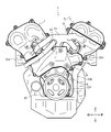
- FIG. 2 is a diagram showing a timing belt in an internal combustion engine and a belt cover arranged inside the timing belt;
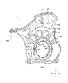
- FIG. 4 is a diagram showing a belt cover arranged outside the timing belt in the internal combustion engine;
- FIG. 4 is a side view of the internal combustion engine showing a state in which the belt cover is attached; It is the perspective view which looked at the lower side cover from the outside.
- FIG. 4 is a perspective view showing a state in which the side mount bracket is attached to the lower cover; It is the figure which looked at the state which removed the side mount bracket from the water pump case from the downward direction.
- FIG. 10 is a perspective view for explaining how the side mount bracket is attached to the upper member; It is a perspective view explaining arrangement
- FIG. 4 is a cross-sectional view for explaining a seal structure and a fastening structure above the side mount bracket 8;
- FIG. 1 shows a timing belt TB in an internal combustion engine 1 and a belt cover arranged inside the timing belt TB.
- FIG. 2 shows a belt cover arranged outside the timing belt TB in the internal combustion engine 1.
- the inner side and the outer side here refer to the side closer to the cylinder head CH, CH or the cylinder block CB of the internal combustion engine 1 with respect to the timing belt TB as the inner side, and the opposite side to the outer side.
- crankshaft 10 and camshafts 11, 12, 13, and 14 are arranged so as to protrude from cylinder heads CH, CH and cylinder block CB on one side of the internal combustion engine 1 .
- Crankshaft 10 and camshafts 11, 12, 13 and 14 are connected to drive pulleys 15, 16, 17, 18 and 19, respectively.
- a timing belt TB is stretched over the drive pulleys 15, 16, 17, 18, 19 and other pulleys.
- the timing belt TB is protected by a belt cover.
- the belt cover is attached to one side surface of the internal combustion engine body and accommodates the timing belt TB.
- the belt cover of this embodiment includes a front inner cover 2, a rear inner cover 3, an upper outer cover 4, a lower outer cover 5, a rear outer cover 7, a side mount bracket 8, and a lower cover 9. have.
- a sealing member or the like is arranged between the covers to seal the gaps.
- the belt cover as a whole accommodates the timing belt TB in a liquid-tight state by sealing the spaces between the covers by arranging sealing members or the like.
- a procedure for assembling the belt cover of this embodiment will be described with reference to FIGS.
- the front inner cover 2 and the rear inner cover 3 are assembled to the cylinder heads CH, CH, as shown in FIG.
- An oil pump case OP and a water pump case WP are assembled to one side surface of the cylinder block CB.
- the lower cover 9 is attached so as to cover the periphery of the crankshaft 10, and the side mount bracket 8 is attached above the lower cover 9 so as to be adjacent thereto.
- the rear outer cover 7 is then mounted above and adjacent to the side mount bracket 8, covering the outside of the drive pulleys 18, 19 of the camshafts 13, 14.
- the lower outer cover 5 is attached above and adjacent to the side mount bracket 8
- the upper outer cover 4 is attached above and adjacent to the lower outer cover 5 .
- the upper outer cover 4 and the lower outer cover 5 together constitute a front outer cover 6 that covers the outer sides of the drive pulleys 16 and 17 of the camshafts 11 and 12 .
- the front outer cover 6 is arranged forward of the rear outer cover 7 .
- Fig. 3 is a side view of the internal combustion engine 1 showing a state in which the belt cover is assembled.
- a crank pulley 20 is connected to the crankshaft 10
- a pipe 21 is arranged outside the front outer cover 6 and the rear outer cover 7, and a side A pipe 22 is arranged outside the mount bracket 8 .
- FIG. 4 is a perspective view of the lower cover 9 as seen from the outside.
- FIG. 5 is a perspective view showing a state in which the side mount bracket 8 is attached to the lower cover 9. As shown in FIG.
- a mating surface 96c of the side mount bracket 8 is formed on the outer peripheral surface of the upper end of the lower cover 9 so as to surround the oil pump case OP.
- a lower seal member 41 for sealing the lower cover 9 and the side mount bracket 8 is arranged on the mating surface 96c.
- the upper end portion of the side wall of the lower cover 9 has a projecting portion 94b projecting in the direction of the internal combustion engine 1. As shown in FIG.
- a plurality of vibration suppression ribs are arranged on the outer surface of the lower cover 9 in order to increase the rigidity of the lower cover 9 and suppress vibration of the lower cover 9 .
- a plurality of fan-shaped first convex ribs 99b are radially formed on the outer surface of the lower cover 9 with the opening 99a of the crankshaft 10 as the center.
- five I-shaped second convex ribs 99c are arranged on the outer surface of the lower cover 9 so as to be adjacent to the first convex ribs 99b in the circumferential direction.
- the projection height of the second convex rib 99c is formed to be lower than that of the first convex rib 99b.
- the second convex ribs 99c provided between the first convex ribs 99b increase the rigidity of the lower cover 9, suppressing film surface vibration of the lower cover 9 due to driving of the crankshaft 10 and the timing belt TB. and the vibration of the mating surface 96c is suppressed. Therefore, the sealing performance of the mating surface 96c can be maintained without fastening with a separate fastening bolt or the like, and deterioration due to vibration of the lower seal member 41 can be reduced.
- the number of each rib is not limited to the number of ribs of this embodiment.
- a mating surface 96c of the lower cover 9 is formed on the outer peripheral surface of the upper end of the lower cover 9, in a direction that intersects the vertical direction (a direction away from the internal combustion engine 1 in the axial direction and a longitudinal direction).
- the mating surface 96c of the mating surface 96c of the lower cover 9 is aligned with the side mount bracket 8.
- a lower seal member 41 for sealing the lower cover 9 and the side mount bracket 8 is arranged on the mating surface 96c.
- the lower seal member 41 is fitted into a groove formed in the mating surface 96c of the lower cover 9. As shown in FIG.
- the side mount bracket 8 is held above the lower cover 9 and adjacent to the cylinder block CB.
- the side mount bracket 8 is formed with a mating surface 86 c of the side mount bracket 8 that is mated with the mating surface 96 c of the lower cover 9 .
- the mating surface 86 c of the side mount bracket 8 is formed on the inner surface of the lower end of the side mount bracket 8 .
- the mating surface 86c of the side mount bracket 8 is configured to cover the mating surface 96c of the lower cover 9 from the outside.
- the upper end of the side mount bracket 8 is formed with a groove in which the first upper seal member 51 and part of the second upper seal member 52 are arranged. The first upper seal member 51 and the second upper seal member 52 will be described later.
- the mating surface 86c of the side mount bracket 8 is pressed against the mating surface 96c of the lower cover 9 via the lower seal member 41. Fixed. This fixation is performed by a fastening member such as a fastening bolt (not shown).
- the lower seal member 41 is made of an elastic member. In this way, the side mount bracket 8 is axially pressed and fixed to the lower cover 9, and covers the lower cover 9 in the axial direction and in the lateral direction (front-to-rear direction) in the drawing that intersects the axial direction. become.
- FIG. 6 is a bottom view of the side mount bracket removed from the water pump case.
- the water pump case WP has a drive pulley 31 that drives the water pump.
- the side mount bracket 8 is configured such that one side (front) end 8a in the width direction (front-rear direction) of the side mount bracket 8, which is a direction perpendicular to the axial direction of the crankshaft 10, covers the water pump case WP. be.
- the side mount bracket 8 is configured such that the other (rear) end 8b in the width direction is fixed to the outer surface 37 of the water pump case WP.
- the side mount bracket 8 and the water pump case WP are fastened by inserting the fastening bolt 38 into the bolt boss portion extending from the side mount bracket 8 through the water pump case WP to the cylinder block CB. Fixed.
- the fixing method is not limited to this.
- the side mount bracket 8 is moved in the front-rear direction when it is attached to or detached from the water pump case WP. Specifically, when attaching the side mount bracket 8 to the water pump case WP, the side mount bracket 8 is moved rearward from the front and then fixed to the water pump case WP. On the other hand, when removing the side mount bracket 8 from the water pump case WP, the side mount bracket 8 is moved from the rear to the front after the fixation of the side mount bracket 8 is released.
- the height H1 of the front end 8a of the side mount bracket 8 is configured to cover the front and outside of the front end 36 of the water pump case WP.
- the height H2 of the rear end portion 8b of the side mount bracket 8 is configured to be the same height as the height H3 of the rear outer surface 37 of the water pump case WP.
- the rear end 8b of the side mount bracket 8 is fastened and fixed to the rear outer surface 37 of the water pump case WP. Therefore, by increasing the height H3 of the rear outer surface 37 of the water pump case WP, the axial length L1 of the rear end portion 8b of the side mount bracket 8 can be shortened.
- a pipe 22 is arranged outside the side mount bracket 8 from above to behind the side mount bracket 8 (see FIG. 1). Therefore, by shortening the axial length L1, it is possible to reduce the amount of movement in the axial direction when attaching and detaching the side mount bracket 8, and it is possible to further improve the ease of attachment and detachment of the side mount bracket 8. .
- FIG. 7 is a perspective view for explaining how the side mount bracket 8 is attached to the upper member.
- the front assembled configuration such as the side mount brackets 8 and the front outer cover 6 will be described in detail.
- the rear assembly structure of the side mount bracket 8, the rear outer cover 7, the rear inner cover 3, etc. is the same in that it relates to the side mount bracket 8, the water pump case WP, and the cylinder block CB.
- the side mount bracket 8 are a front inner cover 2 that covers the timing belt TB on the side closer to the internal combustion engine 1 than the timing belt TB, and a front outer cover that covers the timing belt TB on the side farther from the internal combustion engine 1 than the timing belt TB.
- a cover 6 is arranged.
- the side mount bracket 8 is fixed to the lower outer cover 5 of the front outer cover 6 .
- the front inner cover 2 covers the inside of the camshafts 11 and 12 and the driving pulleys 16 and 17.
- the front outer cover 6 surrounds the camshafts 11 and 12 and the drive pulleys 16 and 17 .
- a water pump case WP is arranged adjacent to and below the front inner cover 2 on one axial side surface of the cylinder block CB.
- the side mount bracket 8 is arranged to cover the water pump case WP on the far side (outer side) from the internal combustion engine 1 than the water pump case WP.
- FIG. 8 is a perspective view illustrating the arrangement of the seal members 51 and 52 above the side mount bracket 8.
- FIG. 9 is a cross-sectional view for explaining the sealing structure and fastening structure above the side mount bracket 8. As shown in FIG. As in the above description, only the configuration on the upper front side will be described, but the configuration on the upper rear side is the same.
- the side mount bracket 8 has a first upper seal member 51 and a part of the second upper seal member 52 arranged on a mating surface 81 at the upper end thereof.
- the mating surface 81 is formed with a groove for fitting the first upper seal member 51 and a part of the second upper seal member 52 .
- the first upper seal member 51 is a member that seals between the front outer cover 6 and the side mount bracket 8
- the second upper seal member 52 is a member that seals between the front inner cover 2 and the water pump case WP and the side mount bracket 8 . It is a member that seals between the inner ends.
- the first upper seal member 51 and the second upper seal member 52 are made of elastic members.
- the end 51a of the first upper seal member 51 and the end 52a of the second upper seal member 52 are arranged so as to be pressed against each other.
- the second upper seal member 52 moves upward from a position below the height of the first upper seal member 51 along a stepped shape 81 a formed on the upper mating surface 81 of the side mount bracket 8 . configured to rise toward
- the step shape 81a is configured such that the position where the first upper seal member 51 is arranged is higher than the position where the second upper seal member 52 is arranged in the portion where the step is formed.
- the end portion 51 a of the first upper seal member 51 comes into contact with the end portion 52 a of the second upper seal member 52 .
- the end portion 51a of the first upper seal member 51 and the end portion 52a of the second upper seal member 52 are fastened and fixed by the fastening bolt 61 in the contact direction (front-rear direction).
- the tightening force of the fastening bolt 61 presses the end portion 51a of the first upper seal member 51 against the end portion 52a of the second upper seal member 52, so that the end portion 51a of the first upper seal member 51 and the second upper seal member 51 are pressed together.
- the end portion 52a of the member 52 is pressed against each other.
- the side mount bracket 8, the water pump case WP, and the cylinder block CB are formed with bolt bosses 62 through which fastening bolts 61 are inserted.
- a mating surface 81 of the side mount bracket 8 is formed at the upper end near the bolt boss portion 62 and extends over the front inner cover 2 and the front outer cover 6 .
- the stepped shape 81a formed on the mating surface 81 is such that the first upper seal member 51 is arranged more than the position where the second upper seal member 52 is arranged.
- the mating surface 86c of the side mount bracket 8 is configured to cover the mating surface 96c of the lower cover 9 from the outside, and the side mount bracket 8 and the lower side mount bracket 8 adjacent in the vertical direction are arranged to cover the mating surface 96c of the lower cover 9 from the outside.
- the side cover 9 is fixed in a direction crossing the vertical direction. Thereby, when removing the side mount bracket 8 from the lower cover 9, it can be removed in a direction crossing the vertical direction. In this case, even if it is difficult to remove the side mount bracket 8 upward because other covers (the front outer cover 6 and the rear outer cover 7) are arranged above the side mount bracket 8, The side mount bracket 8 can be easily removed.
- the lower cover 9 and the side mount bracket 8 are fixed in a state of being pressed against each other via the lower seal member 41 . Therefore, it is possible to provide a belt cover for the internal combustion engine 1 that is easy to attach and detach and has sealing properties.
- the rear end portion of the side mount bracket 8 8b is fixed to the outer surface 37 of the water pump case WP.
- the rear end 8b of the side mount bracket 8 does not cover the water pump case WP like the front end 8a. less movement. Therefore, the easiness of attachment and detachment of the side mount bracket 8 can be enhanced.
- the first upper seal member 51 that seals between the front outer cover 6 and the side mount bracket 8 and the second upper seal member that seals between the front inner cover 2 and the side mount bracket 8 The sealing member 52 is arranged so that the ends 51a and 52a are in pressure contact with each other. Thereby, the sealing performance between the first upper seal member 51 and the second upper seal member 52 can be ensured. Also, the water pump case WP is covered with the side mount bracket 8 . For this reason, maintenance of the water pump can be performed by removing the side mount bracket 8 without removing the lower cover 9, so that the attachment and detachment is easy. Therefore, it is possible to provide a belt cover for the internal combustion engine 1 that is easy to attach and detach and has sealing properties.
- the end portion 51a of the first upper seal member 51 and the end portion 52a of the second upper seal member 52 are brought together on the mating surface 81 of the side mount bracket 8 by the fastening force of the fastening bolt 61.
- Stepped shapes 81a are formed so as to press against each other. Accordingly, by inserting the fastening bolt 61 into the bolt boss portion 62 and fastening them, the first upper sealing member 51 and the second upper sealing member 52 are brought into pressure contact with each other, and sealing performance can be ensured.
- the timing belt TB is used as the transmission belt for transmitting the driving force from the crankshaft 10 to the camshafts 11, 12, 13, 14, but it is not limited to this.
- a chain transmission mechanism may be employed in which a transmission belt made up of a timing chain is stretched over a crankshaft drive wheel and a camshaft driven wheel made up of sprockets.
Landscapes
- Engineering & Computer Science (AREA)
- General Engineering & Computer Science (AREA)
- Mechanical Engineering (AREA)
- Chemical & Material Sciences (AREA)
- Combustion & Propulsion (AREA)
- Cylinder Crankcases Of Internal Combustion Engines (AREA)
Priority Applications (2)
| Application Number | Priority Date | Filing Date | Title |
|---|---|---|---|
| US18/557,163 US12140106B2 (en) | 2021-04-30 | 2022-04-25 | Belt cover structure for internal combustion engine |
| JP2023517503A JP7602625B2 (ja) | 2021-04-30 | 2022-04-25 | 内燃機関のベルトカバー構造 |
Applications Claiming Priority (2)
| Application Number | Priority Date | Filing Date | Title |
|---|---|---|---|
| JP2021-078039 | 2021-04-30 | ||
| JP2021078039 | 2021-04-30 |
Publications (1)
| Publication Number | Publication Date |
|---|---|
| WO2022230801A1 true WO2022230801A1 (ja) | 2022-11-03 |
Family
ID=83847232
Family Applications (1)
| Application Number | Title | Priority Date | Filing Date |
|---|---|---|---|
| PCT/JP2022/018695 Ceased WO2022230801A1 (ja) | 2021-04-30 | 2022-04-25 | 内燃機関のベルトカバー構造 |
Country Status (3)
| Country | Link |
|---|---|
| US (1) | US12140106B2 (https=) |
| JP (1) | JP7602625B2 (https=) |
| WO (1) | WO2022230801A1 (https=) |
Cited By (1)
| Publication number | Priority date | Publication date | Assignee | Title |
|---|---|---|---|---|
| US12025051B1 (en) * | 2021-04-30 | 2024-07-02 | Honda Motor Co., Ltd. | Belt cover structure for internal combustion engine |
Families Citing this family (2)
| Publication number | Priority date | Publication date | Assignee | Title |
|---|---|---|---|---|
| USD1075844S1 (en) * | 2022-11-23 | 2025-05-20 | Holley Performance Products, Inc. | Timing cover |
| USD1075845S1 (en) * | 2022-11-23 | 2025-05-20 | Holley Performance Products, Inc. | Timing cover |
Citations (5)
| Publication number | Priority date | Publication date | Assignee | Title |
|---|---|---|---|---|
| JPS57119160U (https=) * | 1981-01-19 | 1982-07-23 | ||
| JPS616654U (ja) * | 1984-06-19 | 1986-01-16 | トヨタ自動車株式会社 | オ−バヘツドカムシヤフト式のv型エンジン |
| JPS61183445U (https=) * | 1985-05-08 | 1986-11-15 | ||
| JPH0250050U (https=) * | 1988-09-28 | 1990-04-06 | ||
| JPH02105501U (https=) * | 1989-02-07 | 1990-08-22 |
Family Cites Families (3)
| Publication number | Priority date | Publication date | Assignee | Title |
|---|---|---|---|---|
| JPS61179351U (https=) | 1985-04-30 | 1986-11-08 | ||
| JP2741078B2 (ja) * | 1989-09-21 | 1998-04-15 | 本田技研工業株式会社 | V型水冷エンジンのカム軸駆動装置 |
| JP2820765B2 (ja) * | 1990-03-30 | 1998-11-05 | マツダ株式会社 | Dohcエンジンの補機取付構造 |
-
2022
- 2022-04-25 WO PCT/JP2022/018695 patent/WO2022230801A1/ja not_active Ceased
- 2022-04-25 US US18/557,163 patent/US12140106B2/en active Active
- 2022-04-25 JP JP2023517503A patent/JP7602625B2/ja active Active
Patent Citations (5)
| Publication number | Priority date | Publication date | Assignee | Title |
|---|---|---|---|---|
| JPS57119160U (https=) * | 1981-01-19 | 1982-07-23 | ||
| JPS616654U (ja) * | 1984-06-19 | 1986-01-16 | トヨタ自動車株式会社 | オ−バヘツドカムシヤフト式のv型エンジン |
| JPS61183445U (https=) * | 1985-05-08 | 1986-11-15 | ||
| JPH0250050U (https=) * | 1988-09-28 | 1990-04-06 | ||
| JPH02105501U (https=) * | 1989-02-07 | 1990-08-22 |
Cited By (2)
| Publication number | Priority date | Publication date | Assignee | Title |
|---|---|---|---|---|
| US12025051B1 (en) * | 2021-04-30 | 2024-07-02 | Honda Motor Co., Ltd. | Belt cover structure for internal combustion engine |
| US20240229708A1 (en) * | 2021-04-30 | 2024-07-11 | Honda Motor Co., Ltd. | Belt cover structure for internal combustion engine |
Also Published As
| Publication number | Publication date |
|---|---|
| US12140106B2 (en) | 2024-11-12 |
| JP7602625B2 (ja) | 2024-12-18 |
| US20240229735A1 (en) | 2024-07-11 |
| JPWO2022230801A1 (https=) | 2022-11-03 |
Similar Documents
| Publication | Publication Date | Title |
|---|---|---|
| WO2022230801A1 (ja) | 内燃機関のベルトカバー構造 | |
| EP1160438B1 (en) | Case member mounting structure | |
| US9103428B2 (en) | Structure for coupling V-belt type continuously variable transmission with engine | |
| CN105937441B (zh) | 内燃发动机 | |
| JPWO2022230801A5 (https=) | ||
| JP7470865B2 (ja) | 内燃機関のベルトカバーのシール構造 | |
| CN101737214A (zh) | 具有油泵消声器和噪声衰减器的发动机 | |
| US7841600B2 (en) | Seal member for engine cover of outboard motor | |
| US20240229708A1 (en) | Belt cover structure for internal combustion engine | |
| JP2008286207A (ja) | チェーンケースの取付構造 | |
| WO2022230797A1 (ja) | 内燃機関のベルトカバーのシール構造及び装着方法 | |
| JP2002130051A (ja) | ケース部材の取付構造 | |
| JP3615449B2 (ja) | エンジンのカムプレート装置 | |
| JP4489085B2 (ja) | ケース部材の取付構造 | |
| JPH0735732B2 (ja) | V形構造の内燃機関 | |
| JP4187741B2 (ja) | チェーンケースの取付構造 | |
| JP3937705B2 (ja) | 内燃機関のクランクプーリ取付構造 | |
| JP7395945B2 (ja) | エンジンのカバー構造 | |
| JP4450846B2 (ja) | 内燃機関のタイミングカバー構造 | |
| JP4493673B2 (ja) | ケース部材の取付構造 | |
| JP2000283294A (ja) | シリンダヘッドカバーのシール構造 | |
| JPH0510755U (ja) | エンジンの遮音装置 | |
| JP2023108757A (ja) | 内燃機関 | |
| CN115523052A (zh) | 一种铝压铸发动机边盖 | |
| JP4804568B2 (ja) | 内燃機関のタイミングカバー構造 |
Legal Events
| Date | Code | Title | Description |
|---|---|---|---|
| 121 | Ep: the epo has been informed by wipo that ep was designated in this application |
Ref document number: 22795714 Country of ref document: EP Kind code of ref document: A1 |
|
| WWE | Wipo information: entry into national phase |
Ref document number: 18557163 Country of ref document: US |
|
| WWE | Wipo information: entry into national phase |
Ref document number: 2023517503 Country of ref document: JP |
|
| NENP | Non-entry into the national phase |
Ref country code: DE |
|
| 122 | Ep: pct application non-entry in european phase |
Ref document number: 22795714 Country of ref document: EP Kind code of ref document: A1 |